
Sunflower Seed Suction Stability Regulation and Seeding Performance Experiments


1
College of Mechanical and Electrical Engineering, Inner Mongolia Agricultural University, Hohhot 010000, China
2
Changzhou Vocational Institute of Mechatronic Technology, Changzhou 213000, China
*
Author to whom correspondence should be addressed.
†
These authors contributed equally to this work.
Agronomy 2023, 13(1), 54; https://doi.org/10.3390/agronomy13010054
Submission received: 29 September 2022
/
Revised: 17 December 2022
/
Accepted: 19 December 2022
/
Published: 23 December 2022
(This article belongs to the Section Agricultural Biosystem and Biological Engineering)
Abstract
:The poor adsorption stability of the current air-suction sunflower seed-metering devices under high-speed operation leads to unstable seed adsorption posture, as well as increases in the multiple and miss indices. In order to improve the stability of seed adsorption, an air-suction sunflower seed-metering device based on structure-assisted stable suction posture was designed, the movement mechanism of the seed absorption process and the seed-feeding process is analyzed, following which mathematical models of the processes are established, and the key factors affecting the seeding performance were determined. Furthermore, the shape parameter equation of sunflower seeds is fitted, depending on the dimensions and shape parameters, which provides the design basis for the key components of the seed-metering device. Moreover, in order to optimize the seed-metering devices structure, taking the depth, width, and length of the seed suction grooves as experimental factors, as well as the qualified, multiple, and miss indices as evaluation indices, an orthogonal regression experiment considering three factors and three levels is carried out using the Box–Behnken experimental design. Finally, multiple regression models are established and extreme value theory is used to optimize the parameters of the influencing factors and obtain optimal parameter combinations. The optimal parameter combination is as follows: width of the suction groove, 10.5 mm; depth, 3 mm; and length, 23 mm. Results from verification experiments revealed the corresponding experimental indicators, the qualified index is 91.63%, the multiple index is 5.63%, and the miss index is 2.74%, thus meeting the requirements of effective sunflower seed sowing.
1. Introduction
As one of the most important oil crops in the world, sunflower has high nutritional and economic value. The main sunflower-producing areas in the world are Ukraine, Russia, the European Union, China, Argentina. and other countries. Sunflower cultivation in China is mainly distributed in the three provinces of Northeast China, parts of North China, and parts of Northwest China [1,2]. The yield of sunflower is affected by many factors, of which precision sowing technology is one of the important [3]. The existing precision seeders can be divided into mechanical and pneumatic types. Air-suction seed-metering devices are widely used, due to their strong adaptability, low seed injury rate, and high-speed operation [4,5].
For seeds with high sphericity degree, such as soybean, millet, and corn, air-suction seed-metering devices have achieved better results [6,7,8,9]. Lai et al. [10] have designed a kind of air-suction ultra-narrow-row device to achieve high-density precision seeding of Panax notoginseng by combining pneumatic and nesting wheel-type seed-metering devices. Shi et al. [11] have designed a kind of air-suction precision seed-metering device with guided seed-filling plate to improve the singulation index (SI) of the seed-meter at high speed, in order to provide a reference for further improving the precision of the seed-metering device. Li et al. [12] have designed a pneumatic precision seed-metering device with a single seed-metering plate for double-row, which can facilitate the precise and high-speed seeding of many kinds of legume crops. Yi et al. [13] have designed a millet hill-drop seed-metering device with a combination of positive–negative pressure and hole wheel, using negative pressure to assist seed filling and positive pressure for cleaning seeds, thus resolving the problems of millet sowing hole blocking and poor seed-metering uniformity. ONAL [14], Molin, J.P. [15], Yazgi, A. [16], Ahmad, F. [17], and other researchers have taken soybean and corn seeds as research objects, and analyzed the effects of different hole number, vacuum degree, cultivated land conditions, and machine sowing speed on the performance of air-suction seed-metering using computer measurement systems (CMSs). The working parameters of the air-suction seed-metering device on seed-metering performance were analyzed theoretically. Han et al. [18] have conducted a simulation of the gas–solid flow in an inside-filling air-blowing maize precision seed-metering device by means of a coupling approach using the discrete element method (DEM) and computational fluid dynamics (CFD), which can provide a theoretical basis for assessment of the potential working performance of an inside-filling air-blowing seed-metering device. Li et al. [19] have derived the relationship between the drag force model and the suction force model, which was studied by comparing the predicted value of the drag force and the measured value of the suction force under the same conditions.
Due to the irregular shape of sunflower seeds, the general air-suction seed-metering device presents different suction posture in the working process, affecting the seed suction stability and seeding performance [20]. Gong et al. [21] have found that, due to the differences in posture, the suction area of seeds will change in the actual suction process: the greater the suction area, the greater the suction capacity of seeds. Li et al. [22,23] have found that the suction posture of seeds affects the seed-metering performance by affecting the unloading process. Ding et al. [24] have found that the difference in suction posture will affect the qualified index, multiple index, and miss index of the seed-metering device. Li et al. [25] have established a probabilistic model of wheat seed filling posture. He et al. [26] have effectively improved the problems existing in traditional seed-metering devices, such as the high miss rate and poor seed-filling effect, by limiting the posture of wheat seed filling. Lin et al. [27] have constructed a critical negative pressure model of a seed-metering device by analyzing the relationship between different postures and the actual contact area.
In summary, in order to resolve the problem that the seed-metering device presents sub-optimal performance during the working process due to unstable suction posture, the phenomena of re-suction and mis-suction in seed-filling and -suction areas, excessive seed clearance in seed-cleaning areas, seed drop in seed-carrying areas, and abnormal seed posture in seed-carrying areas, in this paper, through a mechanical and kinematic analysis of the seed-unloading and seed-suction areas, the key factors affecting the seed suction stability are determined. Consequently, an air-suction sunflower seed-metering device based on structure-assisted suction posture stabilization is designed, in order to improve the working quality of the seed-metering device.
2. Materials and Methods
2.1. Structure and Working Principle of the Seed-Metering Device
A seed-metering device is mainly composed of a seed box, a seed-metering plate, a pair of seed adjustment devices, a seed-cleaning device, a seed-stirring device, an air chamber, and a transmission shaft, as shown in Figure 1. The seed-metering plate is the core part of the seed-metering device, with structure composed of a seed suction groove and a seed-metering plate body. The seed suction grooves are uniformly distributed on the seed-metering plate body by glue, and the seed stirring device is connected to the seed-metering plate by bolts. One end of the seed-metering plate is a seed box, the other end is air chamber, there is a divider in the middle of the seed box, and there is a seeding port at the lower end. The seed box and the air chamber are connected by bolts, and the seed-metering plate is clamped in the middle, playing a sealing role. The seed-cleaning device and the adjusting device are connected to the seed box through the positioning slot. The transmission shaft is fixed to the air chamber through a bearing, and is connected with the center hole of the seed-metering plate to drive the rotation of the seed-metering plate.
The working process of the seed-metering device is divided into six parts: Seed filling, seed suctioning, seed adjusting, seed cleaning, seed carrying, and seed unloading (See Figure 2). Driven by the transmission shaft, the seed-metering plate and the seed stirring device rotate synchronously to stir the population in the seed-filling area, in order to increase its mobility. Under the action of external force and seed gravity, the seeds are absorbed away from the population by the seed suction groove, achieving seed suctioning. When two or more seeds enter the seed suction groove, the seed-cleaning device is pushed away from the dominant suction area under its action, and the seeds leave the seed suction groove and re-enter the seed box under their own gravity. After passing through the seed-cleaning area, the seeds are stably adsorbed in the seed suction groove and moved to the seed-unloading area through the seed-carrying area. After entering the seed-unloading area, the vacuum negative pressure disappears, and the sunflower seeds break away from the seed-metering plate under the action of their own gravity and discharge from the seed-metering device through the seeding part, thus completing the seeding process.
2.2. Design and Parameter Analysis of Key Components
In this paper, based on the triaxial dimensions of sunflower seeds, the shape structure of sunflower seeds is extracted, in order to design the key components of the air-suction sunflower seed-metering device with stable suction posture.
2.2.1. Triaxial Dimension Measurement and Outline Extraction of Seeds
The triaxial dimensions of sunflower seeds provide important reference for the design of structural parameters such as seed suction grooves and holes [28]. In this paper, the Inner Mongolia sunflower seed 3638c was taken as the research object, 50 sunflower seeds were randomly selected, and the triaxial dimensions of sunflower seeds were measured with a Vernier Caliper with precision of 0.02 mm. The results are given in Table 1. L, W and H denote as length, width, and thickness, respectively. The triaxial size diagram of the seed is shown in Figure 3.
The histograms of the triaxial measurements are shown in Figure 4, from which it can be seen that the triaxial dimensions of the sunflower seeds basically conform to normal distributions, based on which the seed suction groove was designed.
In order to meet the stable seeding of sunflower seeds and reduce the phenomenon of multi-suction or missing, the actual shape characteristics of sunflower seeds should be considered before designing the seed suction grooves. Fifty seeds were randomly selected, and we captured images from the length–width and length–thickness directions. A binary treatment was used to extract the outlines of the sunflower seeds. Processing examples are shown in Figure 5.
According to the length and width projection contour curve (cross-section) of the sunflower seeds, shown in Figure 6, the upper part can be fitted as an ellipse with W/2 as its short axis and L−W/2 as its long axis, while the lower part can be fitted by circle with W/2 as its radius. The fitted contour parameter equations are as follows:
According to the long and thick projection profile curves (longitudinal section) of the sunflower seeds, shown in Figure 6, the upper part can be fitted with H/2 as the short axis and L−W/2 as the long axis, while the lower part can be fitted with H/2 as the short axis and the W/2 as the long axis. The fitted contour parameter equations are as follows:
The fitting image and the actual contour image area were obtained by drawing in the Cartesian coordinate system. The mean square error of the longitudinal section area was 1.18%, while that of the cross-section area was 3.11%. These results indicate that the fitting contour parameter equation is basically consistent with the actual seed profile, and can be used as a basis for seed suction groove design.
2.2.2. Key Parameter Design of Seed-Metering Plate
The seed-metering plate is a key component of air-suction seed-metering devices, and its size and number of holes directly affect the performance of the seed-metering device [29,30]. According to the relationship between the rotation speed of the seed-metering plate and the filling time, it can be found that:
where t is the filling time (s), α is the filling angle (rad), n is the rotation speed of the metering plate (rpm), vm is the forward speed of the seeder (km/h), N is the number of holes in the metering plate, and X is the number of theoretical holes. Combining Formulas (3) and (4) gives the following:
It can be seen, from Formula (5), that, when the working speed of the machine and the theoretical hole distance X are determined, the seed-filling time t is only related to the number of holes N and the filling angle of the seed plate α. Considering the relationship between the size of the seed plate, the negative pressure chamber, and the seed box, the diameter of the seed plate body is 198 mm, the plate body takes 18 groups of openings, and the angle between the two adjacent holes is 20°. The material is 305 stainless steel with thickness of 5 mm, and its structure is shown in Figure 7.
On one hand, the seed suction groove can stir the population to increase its fluidity; on the other hand, it can also stabilize the seed posture. Under ideal conditions, it is hoped that only a single seed can be contained in a single seed suction groove; too large of a seed suction groove may lead to the uptake multiple seeds at a time, which will increase the multiple index, while too small of a seed suction groove will lead to difficulties in seed filling and increase the miss rate. After obtaining the projection contour curve of sunflower seeds, the seed suction groove parameters were designed and optimized, according to the triaxial size of the sunflower seeds. The structure of the seed suction groove is shown in Figure 8. The length of the seed suction groove lc, the width of the seed suction groove wc, the depth of the seed suction groove hc, and the plane inclination angle γ of the seed suction groove are key parameters that must be considered.
The groove depth hc should not be too deep; namely, Hmax/2 ≤ hc ≤ Hmax/2 should be satisfied. The groove plane inclination angle γ varies with the groove depth, with the purpose of ensuring that the seeds can be planted normally in the planting area. The length of the seed suction groove lc should meet lc ≥ Lmax, with the purpose of ensuring that the seed can smoothly enter the suction groove and the seed suction posture is stable. The width of the suction groove wc should satisfy Wmax ≤ wc ≤ 2Wavg, with the purpose of ensuring that the width of the seed does not affect the seed entering the suction groove while preventing multiple seeds from entering the same groove. According to the agricultural machinery design manual [31], the diameter of seed suction holes is generally related to the average width of seeds, and the formula is as follows:
where dz is the diameter of the suction hole (mm) and b is the width of the seed (mm). Formula (6) indicates that the diameter of suction hole will increase with an increase in seed width. The diameter of suction hole selected in this paper was 4 mm.
dz = (0.64–0.66) b,
2.2.3. Design of the Adjusting Device
The adjusting device is the key component for preventing auxiliary seeds from entering the suction groove, relying on a pair of upper and lower brushes to continuously squeeze the seeds that do not enter the suction groove, such that the seeds with different gestures can enter and stabilize in the suction groove with a certain posture, which is convenient for the following seed-cleaning device. The outline curve of the seed brush is shown in Figure 9.
The initial angle θ1 determines the initial height of the brush. If the initial height is too low, it will affect the collapse and reflux of the seeds in the filling area, restricting the fluidity of the seeds. Through experiments, it was determined that θ1 = 30°.
The adjusting seed angle θ2 determines the adjusting seed length. Through experiments, it was found that when the adjusting seed distance is more than two seed lengths, the seed righting effect will not be affected, as the adjusting seed distance is too short; that is, when lAB ≥ 2Lmax, according to the arc length formula:
where l is the arc length (mm) and n is the center angle (°). According to the actual situation, the adjusting distance was properly extended, and lAB = 49 mm and θ2 ≈ 30° were determined. The starting circle of the upper and lower adjusting seed brush is tangent to the base circle of the suction groove, and the ending circle is tangent to the outline of the suction groove. R1 = 78.5 mm, R2 = 90 mm, R3 = 72 mm, and R4 = 96 mm were selected, according to the actual situation. The tangent of lCD and the starting circle of the lower brush ends at the arc of point D starting from the tangent point C, and the tangent of lEF and the starting circle of the upper brush ends at the arc of point F starting from the tangent point E. Taking the center of the seed-metering plate as the center, the plane Cartesian coordinate system was established, and the parametric equations of the curves lCD and lEF were respectively calculated as:
2.3. Analysis of the Principle of Suction and Movement of Sunflower Seeds
2.3.1. Analysis of the Forces on the Seeds during Suction
The seeds in the seed suctioning area are separated from the population to achieve the purpose of seed suctioning under the action of the suction force. The seeds in the seed suctioning area are adsorbed into the seed suction groove and rotated synchronously with the seed-metering plate. Therefore, to explore the factors affecting the suction stability, in order to ensure that the adsorbed seeds will not slide and roll away from the seed-metering plate, it was necessary to analyze the forces in the seed suction process.
The seed is affected by a variety of external forces. It is assumed that, in the process of seed suction, only a single seed is absorbed by a single groove, all the external forces act on the seed centroid, the surface of the seed suction groove is approximately inclined, and the seed rotates uniformly with the seed plate at an angular velocity ω. We take the seed centroid as the origin o, the seed centroid as the tangential direction, oi, and the seed centroid pointing to the center of the seed-metering plate as the normal direction, oj. The plane of the vertical seeding plate passing through the seed centroid is the secondary normal direction (ok), and a natural coordinate system was established (Figure 10).
According to D’Alembert’s principle, the equilibrium equation is listed as follows:
If the seed does not slip in the process of seed suctioning, the following formula must be satisfied:
Simultaneously considering Formulas (10) and (11), we can obtain the minimum suction vacuum degree in which the seed is adsorbed by the seed suction hole and the seed has no sliding:
If the seed does not roll in the process of seed suctioning, it must satisfy:
By bringing Formula (13) into (10), the minimum suction vacuum degree for the seed to be adsorbed by the suction hole while the seed has no rolling is:
It can be seen, from Formulas (12) and (14), that the small suction vacuum degree Pmin of seeds adsorbed without sliding and without rolling is related to the actual suction area S, the friction coefficient f1 between seeds, the surface friction coefficient f2 between seeds and seed suction grooves, the mass m of seeds, the rotation radius R of seed suction center, rotation angular velocity ω, seed-filling angle α, and suction groove angle β. When the structural parameters of the seed-metering device are determined, the minimum suction vacuum degree Pmin is negatively correlated with the actual suction area S, and positively correlated with the rotation angular velocity ω of various plates. Furthermore, when the working parameters of the seed-metering device are determined, the slope angle of the minimum suction vacuum degree Pmin seed suction groove is tangent; that is, the structure size of the groove and the seed suction posture will directly affect the suction stability.
In order to facilitate the extreme value analysis, we set tanβ = 1, cosα = 1, cosγ = 1, and considering that the seed-metering device is affected by the natural conditions of the seeds and the external environment in practical work, it is also necessary to multiply by the seed suction reliability coefficient K1, working stability reliability coefficient K2, and moisture content influence coefficient K3:
Taking 18 holes with a 1000-grain weight of 120 g, aperture of 2 mm, machine forward speed of 4 km/h, and seed plate speed 11.28 rpm as an example, we set K1 = 2, K2 = 2, K3 = 1.2, f1 = 0.23, and f2 = 0.23. The critical vacuum degree was calculated to be P = 260.59 Pa, P′ = 558 Pa.
The negative pressure value at the suction hole was measured using a ManometerHT-1890 digital differential manometer, and the suction state was observed by using a high-speed camera (high-speed camera set frame rate to 20 fps). The seed missing phenomenon occurred when the suction hole negative pressure was 260 Pa; meanwhile, when the negative pressure reached 560 Pa, the actual seed suction rate was 100%, and there was no mis-suction phenomenon in the suction process. Considering various conditions in the actual working process, including: the difference of seed shape, different posture, mechanical vibration and the fit gap between the air chamber and the seed discharge disc may affect the real negative pressure at the suction hole, so the negative pressure of the suction hole was appropriately increased, and the negative pressure of the suction hole was set as 700 Pa.
2.3.2. Analysis of the Force and Movement of the Seeds during Seeding
When the seed is separated from the suction zone, the negative pressure and the suction force disappear, and the seed overcomes the resistance under its own gravity to achieve the purpose of seeding. Under the influence of the seed-metering plate, the seed will have a certain initial speed when it is separated from the seed-metering device. Therefore, it is necessary to analyze the forces and motion in the seed-feeding process.
The seed is subjected to a variety of external forces in the process of seeding, and the following analysis was made with respect to the critical time of seeding, assuming that all external forces act on the seed centroid, the surface of the suction groove is approximately inclined, and the seed rotates uniformly with the seed plate at an angular velocity ω. We take the seed centroid as the origin o, the rotation direction of the seed plate as the tangent (oi), and the seed centroid pointing to the center of the seed-metering plate as the normal direction (oj). The plane of the vertical seeding plate passing through the seed centroid is the secondary normal (ok), and a natural coordinate system was established (see Figure 11).
In the process of seeding, if the seed is to slip smoothly from the suction groove, the joint force of gravity and centrifugal force is needed to overcome the supporting force and the friction between the seed plates:
From Formula (16), it can be concluded that the necessary condition for the seed to slide out of the suction groove is:
When the seed leaves the metering plate, the seed is affected by the metering plate and has an initial speed. The magnitude and direction of the initial velocity are related to the rotation direction of the metering plate and the rotational speed of the metering plate. This speed should also be used as the initial speed after the seed leaves the metering device. The velocity and force analysis is depicted in Figure 12. The seed is regarded as a particle of mass, and the time when the seed leaves is based on the velocity composition theorem:
When the seed leaves the seed-metering device, the differential equation of motion is as follows:
Assuming that the seed is only affected by gravity and there is no external resistance, the velocity equation of the seed after leaving the seed-metering device can be obtained, from Formulas (18) and (19), as:
From Formulas (17) and (20), it can be seen that the seed-feeding effect in the process of the seed-metering plate is related to the advancing speed of the machine vm, the mass of the seed m, the inclination angle of the suction groove β, the position angle α, the rotation angular velocity ω, the rotation radius R of the suction hole center, the friction coefficient f2 between the seed and the suction groove, and the gravity G of the seed. When the working parameters of the seed-metering device are determined, the groove shape, material, position, and height all directly affect the effect of the seed-metering device.
Through extreme value analysis, using the 3D printing material PLA, f2 = 0.72 and β ≤ 54.25° were obtained. The seeding process was observed by high-speed camera. When β = 51.34°, the seeds could not fall out of the suction groove and entered the filling area for the second time, resulting in an increase in the mis-sowing rate.
2.4. Seeding Performance Test
2.4.1. Test Equipment and Materials
In order to verify the working performance of the designed air-suction sunflower seed-metering device, based on structure-assisted stable suction posture, 3638c sunflower seeds were selected for a seed-metering test. The test equipment was composed of the JPS-12 seed-metering performance test bench developed by Heilongjiang Agricultural Machinery Engineering Research Institute, and the air-suction sunflower seed-metering device with stable suction posture, as shown in Figure 13.
2.4.2. Test Methods and Evaluation Indicators
According to GB/T6973-2005 “single seed (precision) seeder test method”, the qualified index, multiple index, and miss index were taken as evaluation indices for the test. The experiment was repeated three times in each group, the average value of the test results was taken three times. A seed distance of 250 seeds in each group was counted. The width of the seed suction groove A, the depth of the seed suction groove B, and the length of the seed suction groove C are the key factors affecting the suction stability in the process of seed-metering, so, they were selected as the three factors in the parameter optimization test and determine the range of factor levels based on the maximum triaxial size of the measured sunflower seeds [32]. In order to obtain the best parameters for the three factors, the Box–Behnken experimental design principle was adopted; the experimental factor coding table is provided in Table 2.
2.4.3. Calculation Methods of Evaluation Indicators
Seed spacing was recorded separately according to GB/T6973-2005, and seed spacing was divided into five intervals according to theoretical hole spacing, and the number of seeds in each interval was counted as n1, n2, n3, n4 and n5. Defining the total number of seeds as N, there must be N = n1+n2+n3+n4+n5. The qualified index (Y1), the multiple index (Y2) and the miss index (Y3) are calculated as follows:
3. Results and Discussion
3.1. Test Results
The test scheme and results are provided in Table 3.
3.2. Mathematical Regression Modeling and Significance Testing
Regression analysis of the experimental results was carried out using the design-expert software, and the change laws for the test indices under the influence of each experimental factor were analyzed. The regression model significance tests for the qualified index Y1, multiple index Y2, and miss index Y3 all indicated highly significant results, and the lock of fit test results were not significant, indicating that the regression model fit well within the range of the test. The structure coefficient R2 of the model was greater than 0.96, indicating that the response value was more than 96%.
3.2.1. Qualified Index Regression Model
For the qualified index model, as shown in Table 4, the effects of A, AB, AC, BC, and C2 were extremely significant, C and B2 were significant, and other insignificant factors were excluded. The quadratic polynomial response surface regression model was obtained as:
Y1 = 90.84 – 1.99A + 0.3975C + 1.17AB + 1.71AC – 1.20BC – 2.72A2 – 0.6654B2 – 1.68C2.
3.2.2. Multiple Index Regression Model
For the multiple index model, as shown in Table 5, the effects of A, AC, A2, C2, and BC were extremely significant, and the other insignificant factors were excluded. The quadratic polynomial response surface regression model was obtained as follows:
Y2 = 5.96 – 2.55A – 1.21AC + 0.925BC + 1.31A2 + 2.02C2.
3.2.3. Miss Index Regression Model
For the miss index model, as shown in Table 6, the effects of AB, A2, and B2 were extremely significant, A were significant, and the other insignificant factors were excluded. The quadratic polynomial response surface regression model was obtained as:
Y3 = 5.96 – 2.55A – 1.21AC + 0.925BC + 1.31A2 + 2.02C2.
3.3. Impact of Factors on Evaluation Indicators
The quadratic polynomial response surface regression model was processed using the Origin software, and the influence of the interaction of different factors on the evaluation index was assessed. According to the corresponding surface, the level of one of the factors was fixed, and the influences of the remaining two interactions on the evaluation index were analyzed. The effects of the same interactive items on different evaluation indicators significantly differed. Here, we only analyze the impact of significant interaction items on the evaluation indicators.
3.3.1. Effect of Factors on the Qualified Index
Figure 14a shows the response surface of the interaction between groove width and depth on the qualified index when the groove length is 23 mm. As can be seen from the figure, when the depth of the fixed groove is constant, with an increase in the width of the groove, the qualified index increases first and then decreases. When the width of the fixed groove is constant, the qualified index increases first and then decreases with an increase in the groove depth. When the width of the suction groove is 10–11 mm and the depth of the suction groove is 2.75–3.25 mm, the qualified index of the seed-metering device is higher.
Figure 14b shows the response surface of the interaction between groove width and length on the qualified index when the groove depth is 3 mm. As can be seen from the figure, when the length of the fixed groove is constant, with an increase in the width of the groove, the qualified index increases first and then decreases. When the width of the fixed groove is constant, the qualified index increases first and then decreases with an increase in the groove length. When the width of seed suction groove is 10–11 mm and the length of the seed suction groove is 22.5–23.5 mm, the qualified index of seed-metering device is higher.
Figure 14c shows the response surface of the interaction between groove length and depth on the qualified index when the groove width is 11 mm. As can be seen from the figure, when the depth of the fixed groove is constant, with an increase in the groove length, the qualified index increases first and then decreases. When the length of the fixed groove is constant, the qualified index increases first and then decreases with an increase in the groove depth. When the depth of seed suction groove is 2.75–3.25 mm and the length of seed suction groove is 22.5–23.5 mm, the qualified index of the seed-metering device is higher.
3.3.2. Effect of Factors on the Multiple Index
Figure 15a shows the response surface of the interaction between groove width and length on the multiple index when the groove depth is 3 mm. As can be seen from the figure, when the depth of the fixed groove is constant, the multiple index increases gradually with an increase in the groove width. When the width of the fixed groove is constant, the multiple index fluctuates around a certain value with an increase in the groove length. When the width of the suction groove is 10–11 mm and the length of the suction groove is 22.5–23.5 mm, the multiple index of the seed-metering device is lower.
Figure 15b shows the response surface of the interaction between groove length and depth on the multiple index when the groove width is 11 mm. As can be seen from the figure, when the fixed groove depth is constant, the multiple index fluctuates around a certain value with an increase in groove length. When the fixed groove length is constant, the multiple index decreases first and then increases with an increase in groove depth. When the depth of the suction groove is 3–3.5 mm and the length of the suction groove is 22.5–23.5 mm, the multiple index of the seed-metering device is lower.
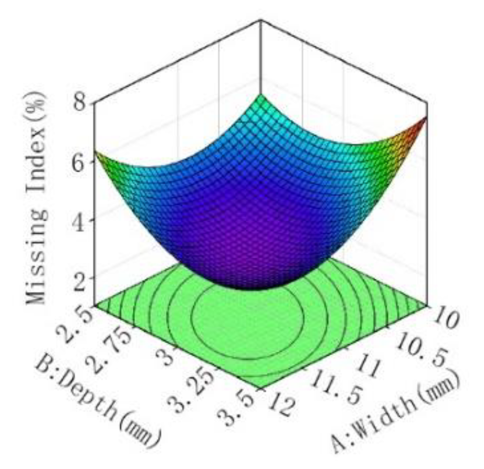
3.3.3. Effect of Factors on the Miss Index
Figure 16 shows the response surface for the effect of groove width and depth interaction on miss index when the groove length is 23 mm. As can be seen from the figure, when the depth of the fixed groove is constant, the miss index decreases with an increase in the width of the groove. When the width of the fixed groove is constant, the miss index decreases first and then increases with an increase in the groove depth. When the width of the seed suction groove is 10–11 mm and the depth of the seed suction groove is 2.75–3.25 mm, the miss index of the seed-metering device is lower.
3.4. Optimal Parameter Combinations and Validation Tests
In order to obtain the best combination of suction hole size parameters, the maximum qualified index, the minimum multiple index, and minimum miss index were taken as the optimal evaluation indices, and extreme value theory was used to solve the associated problem [33,34]. The optimization function and constraint conditions are provided in Formula (24). By using the optimal groove size parameter optimization, the best parameter combination was obtained when the groove width was 10.5 mm, the groove depth was 3 mm, and the groove length was 23 mm. In this case, the qualified index predicted by the model was 91.17%, the multiple index was 5.41%, and the miss index was 3.42%.
A verification test of the optimization result was carried out and, under the same conditions (suction groove width of 10.5 mm, groove depth of 3 mm, and groove length of 23 mm), we repeated the experiments three times. The results indicated that the average qualified index of the seed-metering device was 91.63%, and all of the runs were higher than 90%; the average multiple index was 5.63%, and all runs were less than 6.5%; and the average miss index was 2.74%, with all runs less than 4%. Therefore, the test results were in good agreement with the optimization results, as detailed in Table 7.
4. Conclusions
In order to improve the working stability of the sunflower seed-metering device, An air-suction sunflower seed-metering device was designed, and the problem of unstable seed posture in the seed-metering process of the air-suction seed-metering device was resolved by means of mechanical pneumatic coupling.
The movement mechanism of the seed absorption process and the seed-feeding process is analyzed, following which mathematical models of the processes are established. According to the model, the minimum critical negative pressure for seed suction is 0.7 kPa, and the model shows that the length, width and depth of the suction groove and the material of the suction groove will directly affect the seed discharge performance.
When determining the critical suction pressure, the unstable seed suction caused by the different suction postures can lead to a decrease in the suction force applied to the seeds and a rise in the miss index caused by disengagement from the suction grooves. The difference in seed posture can also cause both seeds to get stuck in the same suction groove, and the seed cleaning device is unable to clear the excess seeds, causing an increase in the multiple index.
In order to optimize the seed-metering devices structure, as orthogonal regression experiment considering three factors and three levels was carried out using the Box–Behnken experimental approach, extreme value theory was used to optimize the parameters of the influencing factors. The optimal parameter combination is as follows: width of the suction groove, 10.5 mm; depth, 3 mm; and length, 23 mm. Results from verification experiments revealed the corresponding experimental indicators, the qualified index is 91.63%, the multiple index is 5.63%, and the miss index is 2.74%, thus meeting the requirements of effective sunflower seed sowing.
Author Contributions
Conceptualization, X.Z., T.Z., F.L. and N.L.; methodology, X.Z. and T.Z.; software, X.Z. and T.Z.; validation, X.Z.; formal analysis, J.L., X.Z. and T.Z.; investigation, X.Z.; resources, X.Z.; data curation, X.Z. and T.Z.; writing—original draft preparation, X.Z.; writing—review and editing, X.Z., T.Z., F.L., J.L. and N.L.; supervision, F.L.; funding acquisition, F.L. and T.Z. All authors have read and agreed to the published version of the manuscript.
Funding
This work was supported by The National Natural Science Foundation of China (32060418) and Natural Science Foundation of Inner Mongolia Autonomous Region of China (2020BS05024) and Program for Young Talents of Science and Technology in Universities of Inner Mongolia Autonomous Region (No. NJYT-20-B03). The authors give thanks for their generous financial assistance.
Data Availability Statement
The data provided in this study are available upon request from the corresponding author.
Conflicts of Interest
The authors declare no conflict of interest.
References
- United States Government Printing Office. United States Department of Agriculture Agricultural Statistics 1938–2018; United States Government Printing Office: Washingot, DC, USA, 2018.
- Zang, Y.; Zhang, L. The causes of Trade changes of Sunflower products in China—An empirical Analysis based on CMS Model. World Agric. 2020, 7, 53–60+84. [Google Scholar] [CrossRef]
- Li, Y. Investigation on present situation and Forecast of Development Prospect of Sunflower Industry. Agric. Dev. Equip. 2020, 41+44. [Google Scholar]
- Fei, L.; Zhen, L.; Dapeng, L.; Tao, Z. Design optimization and performance test of magnetic pickup finger seed metering device. INMATEH-Agric. Eng. 2021, 63, 137–144. [Google Scholar] [CrossRef]
- Leng, J. Experimental Study on the Performance of Precision Sorghum Seed Platter. Master’s Thesis, Inner Mongolia Agricultural University, Hohhot, China, 2021. [Google Scholar]
- Chen, W.; Zhang, B.; Jiang, L.; Qiu, T.; Wang, L.; Yang, S. Research status and development trend of seed-metering device in China. Am. J. Agric. Res. 2020, 5, 98. [Google Scholar]
- Liao, Q.; Long, X.; Liao, Y.; Ding, Y. Research Progress of Precision Seeding for Rapeseed. Trans. Chin. Soc. Agric. Mach. 2017, 48, 1–16. [Google Scholar] [CrossRef]
- Shang, S.; Wu, X.; Yang, R. Research Status and Prospect of Plot sowing Equipment and Technology. Trans. Chin. Soc. Agric. Mach. 2021, 52, 1–20. [Google Scholar]
- Yang, L.; Yan, B.; Zhang, X.; Zhang, T.; Wang, Y.; Cui, T. Research Progress on Precision Planting Technology of Maize. Trans. Chin. Soc. Agric. Mach. 2016, 47, 38–48. [Google Scholar]
- Lai, Q.; Yu, Q.; Su, W.; Sun, K. Design and Experiment of Air-suction Ultra-narrow-rowDevice for Precise Panax notoginseng Seed Metering. Trans. Chin. Soc. Agric. Mach. 2019, 50, 102–112. [Google Scholar]
- Shi, S.; Zhou, J.; Liu, H.; Zhou, H. Design and Experiment of Pneumatic Precision Seed-metering Device with Guided Assistant Seed-filling. Trans. Chin. Soc. Agric. Mach. 2019, 50, 61–70. [Google Scholar]
- LI, Y.; Yang, L.; Zhang, X.; Cui, T.; Ding, L.; Wei, Y. Design and Experiment of Pneumatic Precision Seed-metering Device with Single Seed-metering Plate for Double-row. Trans. Chin. Soc. Agric. Mach. 2019, 50, 61–73. [Google Scholar] [CrossRef]
- Yi, S.; Chen, T.; Li, Y.; Tao, G.; Mao, X. Design and Test of Millet Hill-drop Seed-metering Device withCombination of Positive-negative Pressure and Hole Wheel. Trans. Chin. Soc. Agric. Mach. 2021, 52, 83–94. [Google Scholar] [CrossRef]
- Onal, I.; Degirjviencioglu, A.; Yazgi, A. An evaluation of seed spacing accuracy of a vacuum type precision metering unit based on theoretical considerations and experiments. Turk. J. Agric. For. 2012, 36, 133–144. [Google Scholar]
- Molin, J.P.; Bashford, L.L.; Bargen, K.V.; Leviticus, L.I. Design and evaluation of a punch planter for no-till systems. Trans. ASAE 1998, 41, 307. [Google Scholar] [CrossRef]
- Yazgi, A.; Degirmencioglu, A. Measurement of seed spacing uniformity performance of a precision metering unit as function of the number of holes on vacuum plate. Measurement 2014, 56, 128–135. [Google Scholar] [CrossRef]
- Ahmad, F.; Adeel, M.a.; Qiu, B.; Ma, J. Sowing uniformity of bed-type pneumatic maize planter at various seedbed preparation levels and machine travel speeds. Int. J. Agric. Biol. Eng. 2021, 14, 165–171. [Google Scholar] [CrossRef]
- Han, D.; Zhang, D.; Jing, H.; Yang, L.; Cui, T.; Ding, Y.; Wang, Z.; Wang, Y.; Zhang, T. DEM-CFD coupling simulation and optimization of an inside-filling air-blowing maize precision seed-metering device. Comput. Electron. Agric. 2018, 150, 426–438. [Google Scholar] [CrossRef]
- Junhong, L.; Qinghui, L.; Hui, Z.; Zhaoguo, Z.; Jinwen, Z.; Tiantian, W. Suction force on high-sphericity seeds in an air-suction seed-metering device. Biosyst. Eng. 2021, 211, 125–140. [Google Scholar]
- Wang, Z.; Zhang, X.; Huang, S.; Chen, W.; Li, J. Rice Seeds Feeding Process in Cell Wheel Based on High-speed Photography Technology. Trans. Chin. Soc. Agric. Mach. 2009, 40, 56–61. [Google Scholar]
- Gong, Z.; Chen, J.; Li, Y.; LI, J. Seed Force in Airflow Field of Vacuum Tray Precision Seeder Device during Suction Process of Seeds. Trans. Chin. Soc. Agric. Mach. 2014, 45, 92–97+117. [Google Scholar] [CrossRef]
- Li, F.; Chen, J.; Liu, F.; Liu, Y.; Zhang, T.; Zhao, M. Influence of seed adsorption posture on seeding performance based on high speed camera technology. J. China Agric. Univ. 2018, 23, 128–136. [Google Scholar] [CrossRef]
- Li, F.; Zhao, M.; Liu, F.; Liu, Y.; Zhang, T. Analysis on the Working Process and the Move ment of Seeds of Air Suction Metering Equipment. J. Agric. Mech. Res. 2018, 40, 150–154. [Google Scholar] [CrossRef]
- Ding, L.; Yang, L.; Zhang, X.; Cui, T.; Zhang, K.; Zhong, X. Effect of Seed Adsorption Posture of Corn Air-suction Metering Device on Seed Feeding Performance. Trans. Chin. Soc. Agric. Mach. 2021, 52, 40–50. [Google Scholar] [CrossRef]
- Li, Z.; Wang, Q.; Zhang, Y.; Wang, W.; Yang, Y.; Zhang, L. Design and Experiment of Inclined Parabolic Cell Wheel in Seed Feeding Device for Wheat. Trans. Chin. Soc. Agric. Mach. 2018, 49, 116–124. [Google Scholar] [CrossRef]
- He, R.; Wang, J.; Xu, G.; He, X.; Duan, Q.; Ding, Q. Design and Experiment of Wheat Precisc Seed Metering Apparatuswith Positive and Negative Pressure with the Function of Limiting Seed Filling Posture. Trans. Chin. Soc. Agric. Mach. 2022, 53, 39–49+167. [Google Scholar]
- Lin, P.; Liao, Q.; Wang, L.; Wang, B.; Liu, H. Seed suction performance and experiment of sesame precision hole seeding metering device. J. Huazhong Agric. Univ. 2021, 40, 195–206. [Google Scholar] [CrossRef]
- Li, Z.; Yang, W.; Zhang, T.; Wang, W.; Zhang, S.; Wei, L. Design and suction performance test of sucking-seed plate combined with groove-tooth structure on high speed precision metering device of rapeseed. Trans. Chin. Soc. Agric. Eng. 2019, 35, 12–22. [Google Scholar] [CrossRef]
- Cao, X.; Ma, X.; LI, H. Design and experiments of pneumatic roller type precision seed-metering device for rapeseed plug seedlings. Trans. Chin. Soc. Agric. Eng. 2021, 37, 51–60. [Google Scholar] [CrossRef]
- Zhang, T.; Liu, F.; Zhao, M.; Liu, Y.; Li, F.; Chen, C.; Zhang, Y. Movement law of maize population in seed room of seed metering device based on discrete element method. Trans. Chin. Soc. Agric. Eng. 2016, 32, 27–35. [Google Scholar] [CrossRef]
- Myer Kutz Associates, Inc. Handbook of Farm, Dairy and Food Machinery; Springer: Dordrecht, The Netherlands, 2007. [Google Scholar]
- Hanqing, L.; Chunjiang, Z.; Bingxin, Y.; Lin, L.; Zhijun, M. Design and Verification of the Variable Capacity Roller-Wheel Precision Rice Direct Seed-Metering Device. Agronomy 2022, 12, 1798. [Google Scholar]
- Haoyi, W.; Xinping, S.; Hua, L.; Jieyi, F.; Xiaoping, Z.; Youzhi, X.; Yongjian, W.; Huaqing, L.; Zhimin, L. Design and Parameter Optimization of a Finger Clip Plate Garlic Seed-Metering Device Based on EDEM. Agronomy 2022, 12, 1543. [Google Scholar]
- Jian, X.; Junwei, H.; Weibin, W.; Chongyang, H.; Xiaoming, W.; Ting, T.; Shunli, S. Key Structure Design and Experiment of Air-Suction Vegetable Seed-Metering Device. Agronomy 2022, 12, 675. [Google Scholar]
Figure 1.
Schematic diagram of the air-suction sunflower seed-metering device: 1. Seed suction groove; 2. Seed-metering plate body; 3. Stirring device; 4. Sunflower seeds; 5. Air chamber; 6. Suction channel; 7. Seed box; 8. Cleaning device; 9. Lower adjusting device; and 10. Upper adjusting device.
Figure 1.
Schematic diagram of the air-suction sunflower seed-metering device: 1. Seed suction groove; 2. Seed-metering plate body; 3. Stirring device; 4. Sunflower seeds; 5. Air chamber; 6. Suction channel; 7. Seed box; 8. Cleaning device; 9. Lower adjusting device; and 10. Upper adjusting device.

Figure 2.
Diagram of the working area: I. Seed-filling area; II. Seed-suctioning area; III. Seed-adjusting area; IV. Seed-cleaning area; V. Seed-carrying area; and VI. Seed-unloading area.
Figure 2.
Diagram of the working area: I. Seed-filling area; II. Seed-suctioning area; III. Seed-adjusting area; IV. Seed-cleaning area; V. Seed-carrying area; and VI. Seed-unloading area.

Figure 3.
Schematic diagram of the triaxial dimensional structure of the seed.
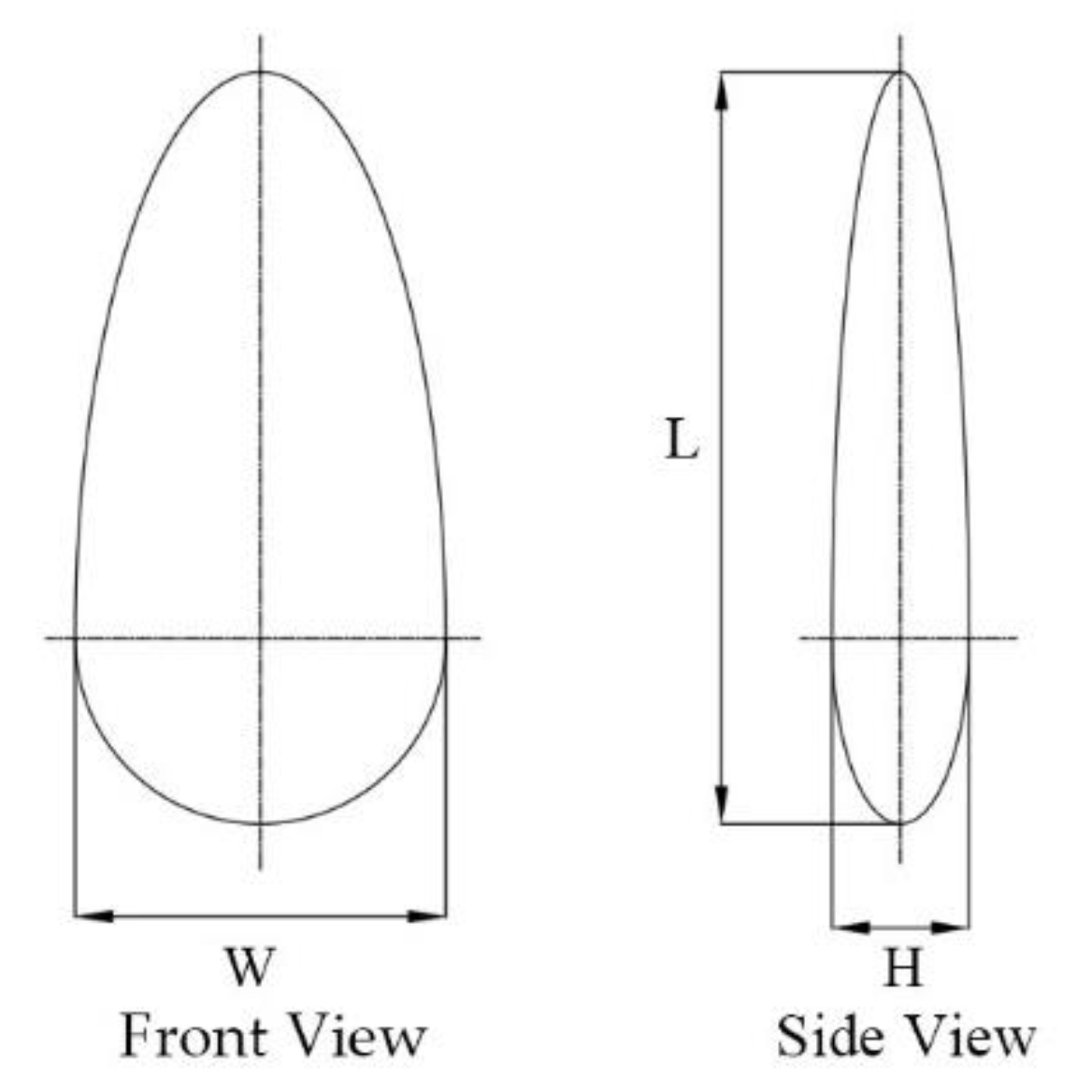
Figure 4.
Frequency distribution histogram of seed triaxial measurements. (a) Length distribution; (b) Width distribution; (c) Thickness distribution.
Figure 4.
Frequency distribution histogram of seed triaxial measurements. (a) Length distribution; (b) Width distribution; (c) Thickness distribution.

Figure 5.
Profile Extraction Fitted Curve Plot: (a). Original image of longitudinal section; (b). Binary image of longitudinal section; (c). Longitudinal profile curve; (d). Longitudinal profile curve and fitted curve; (e). Original image of cross-section; (f). Cross-sectional binary image; (g). Cross-sectional contour curves; and (h). Cross-sectional contour curves and fitted curves.
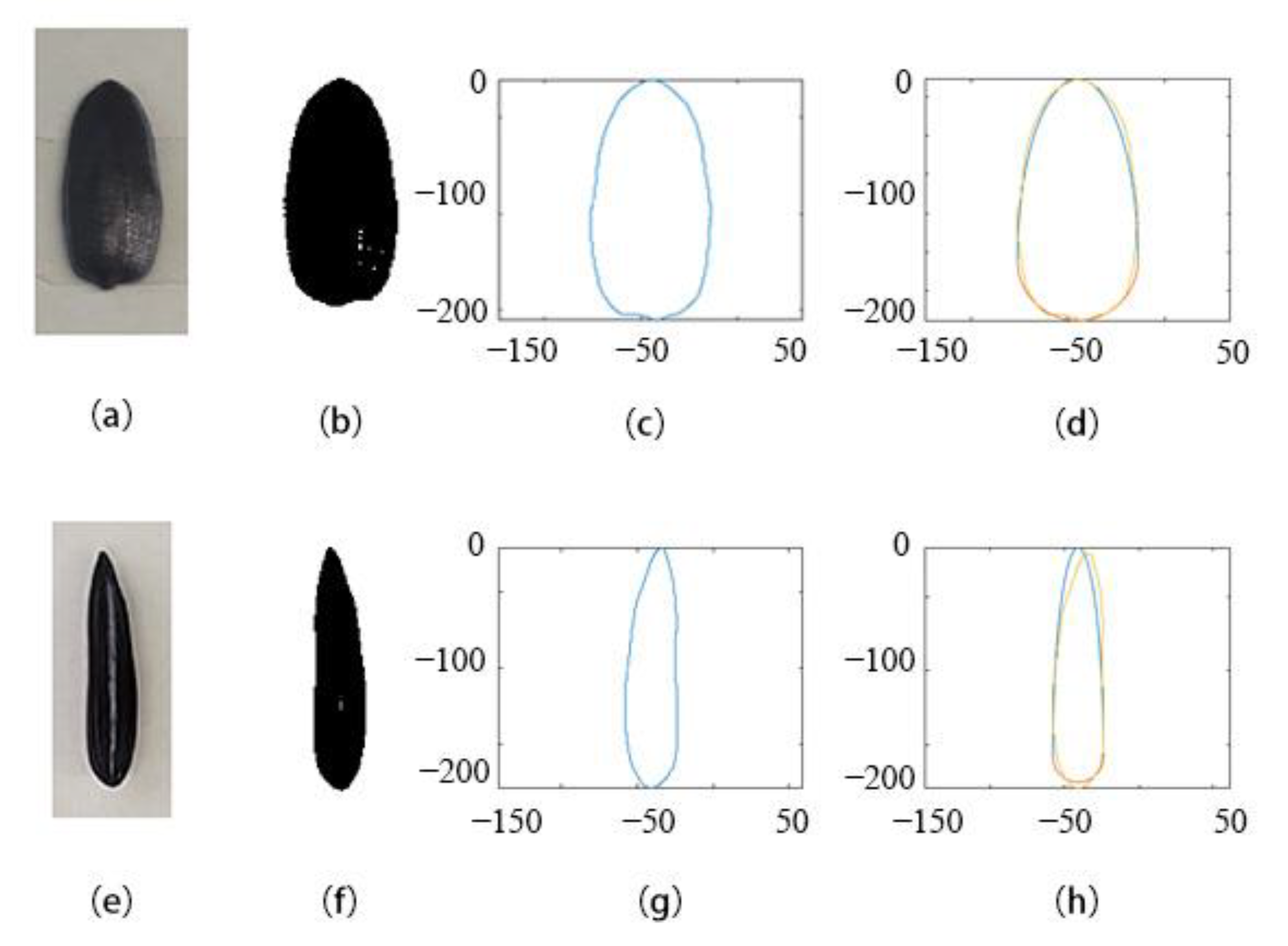
Figure 6.
Fitting contour coordinates.

Figure 7.
Schematic diagram of the structure of the seed tray body: 1. Seed suction groove mounting hole; 2. Seed stirring device positioning hole; and 3. Drive shaft positioning hole.
Figure 7.
Schematic diagram of the structure of the seed tray body: 1. Seed suction groove mounting hole; 2. Seed stirring device positioning hole; and 3. Drive shaft positioning hole.
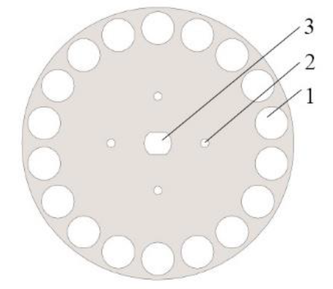
Figure 8.
Schematic diagram of the seed suction groove: (a) The dimensions of the seed suction groove; and (b) 3D view of the seed suction groove.
Figure 8.
Schematic diagram of the seed suction groove: (a) The dimensions of the seed suction groove; and (b) 3D view of the seed suction groove.
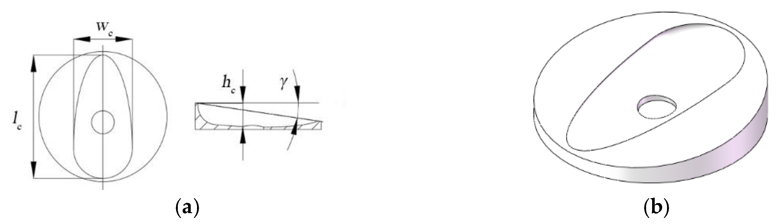
Figure 9.
Illustration of the seed holding brush profile: θ1 is the starting seed adjusting angle; θ2 is the seed adjusting angle; R1 is the starting circle radius of the lower seed adjusting brush; R2 is the ending circle radius of the lower seed adjusting brush; R3 is the starting circle radius of the upper seed adjusting brush; R4 is the ending circle radius of the upper seed adjusting brush; A is the starting point of the seed-cleaning arc; B is the ending point of the seed adjusting arc; C is the starting point of the lower seed adjusting brush; D is the ending point of the lower seed adjusting brush; E is the starting point of the upper seed adjusting brush; and F is the ending point of the upper seed adjusting brush.

Figure 10.
Analysis of the forces on seeds in the seed suctioning zone: G is the seed’s own gravity, N; FP is the seed suction hole suction force, N; J is the centrifugal force, N; F1 is the inter-seed friction force set in the oi negative direction, N; F2 is the frictional force between the seed and the surface of the seed-sucking recess, in a direction perpendicular to the support force N, N; F2i is the component force of F2 in the direction of oi, N; F2j is the component force of F2 in the direction of oj, N; F2k is the component force of F2 in the direction of ok, N; N is the total support force of the seed-sucking recess in the direction perpendicular to the contact point of the recess, N; Ni is the component force of N in the direction of oi, N; Nj is the component force of N in the direction of oj, N; Nk is the component force of N in the direction of ok, N; f1 is the coefficient of friction between the seeds; f2 is the coefficient of friction between the seeds and the surface of the seed-sucking recess; α is the seed-filling angle, °; β is the slope angle of the suction groove, °; ω is the angular speed of rotation of the seed tray, rad/s; γ is the angle between the combined force F′ and the centrifugal force J, °; m is the mass of the seed, kg; R is the radius of rotation of the center of the suction hole of the seed tray, mm; P is the critical suction vacuum degree of the gas chamber, Pa; S is the stable suction area, mm2; Q is the combined force of F1,J and G, N; F′ is the combined force of J and G, N; h is the depth of the contact point between the seed and the suction groove, mm; and w is the width of the contact point between the seed and the suction groove, mm.
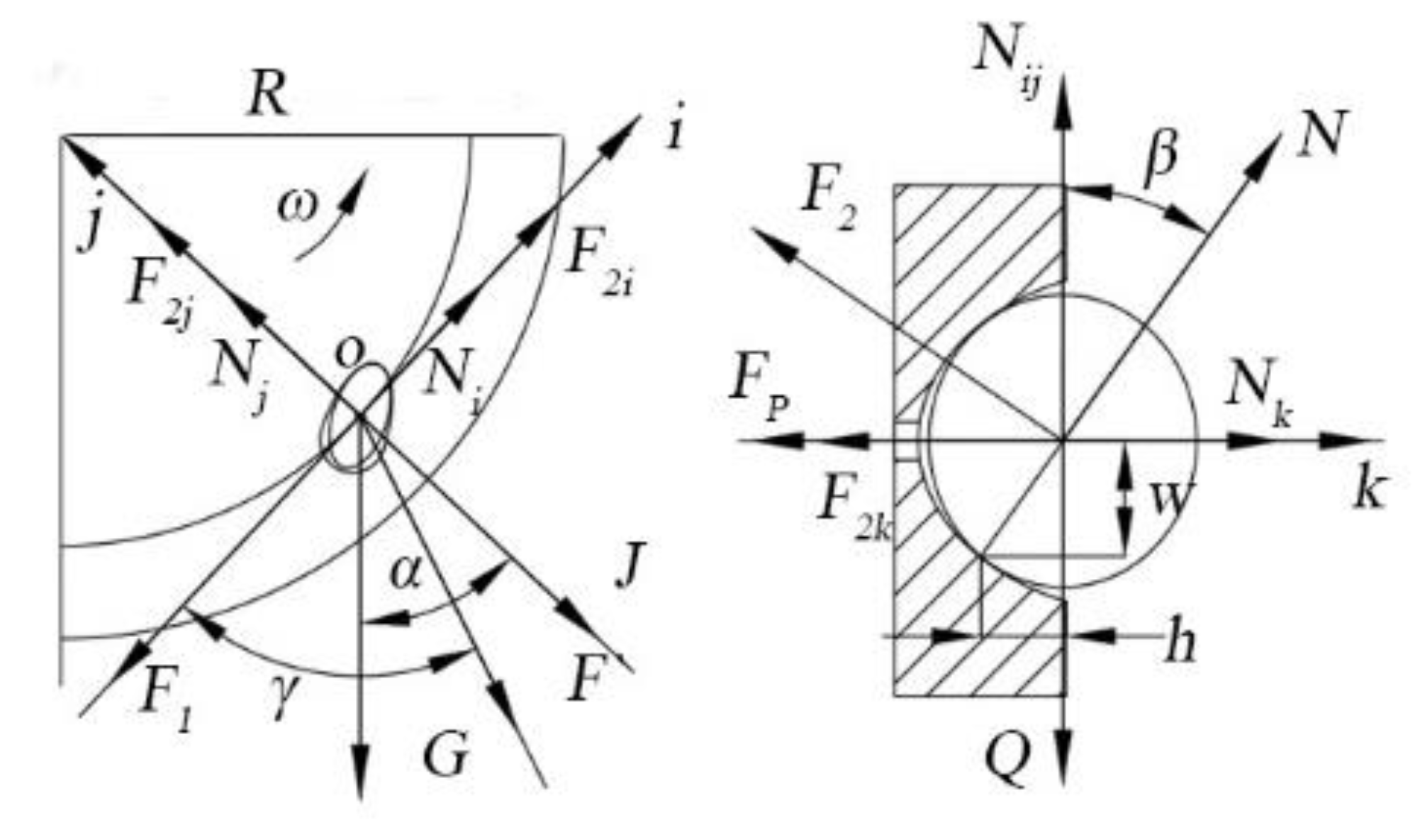
Figure 11.
Analysis of the forces on the seed unloading area: Q2 is the combined force of J and G, N; Δ is the angle of the seeding position, °.
Figure 11.
Analysis of the forces on the seed unloading area: Q2 is the combined force of J and G, N; Δ is the angle of the seeding position, °.
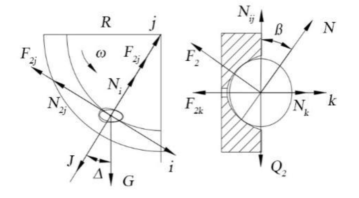
Figure 12.
Velocity and force analysis diagram for the seed unloading area: vx is the horizontal absolute speed, m/s; vy is the vertical absolute speed, m/s; vm is the forward speed of the machine, m/s; vr is the linear speed at the suction hole of the seed discharge disc, m/s; Fx is the external resistance on the x-axis, N; and Fy is the external resistance on the y-axis, N.
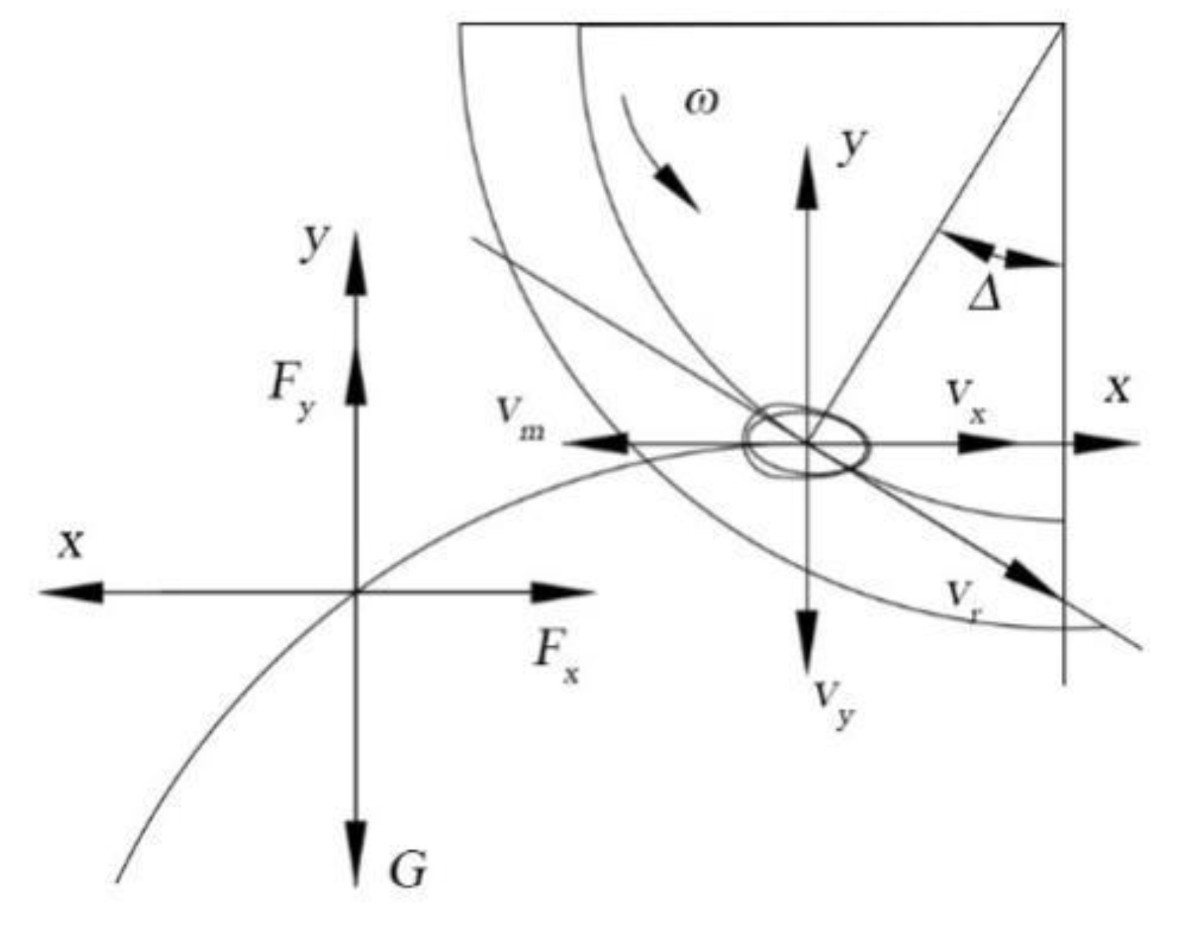
Figure 13.
Seeding performance experimental device: 1. Motor; 2. Seed-metering device; 3. Negative pressure air tube; 4. Table frame; and 5. conveyor belt.
Figure 13.
Seeding performance experimental device: 1. Motor; 2. Seed-metering device; 3. Negative pressure air tube; 4. Table frame; and 5. conveyor belt.
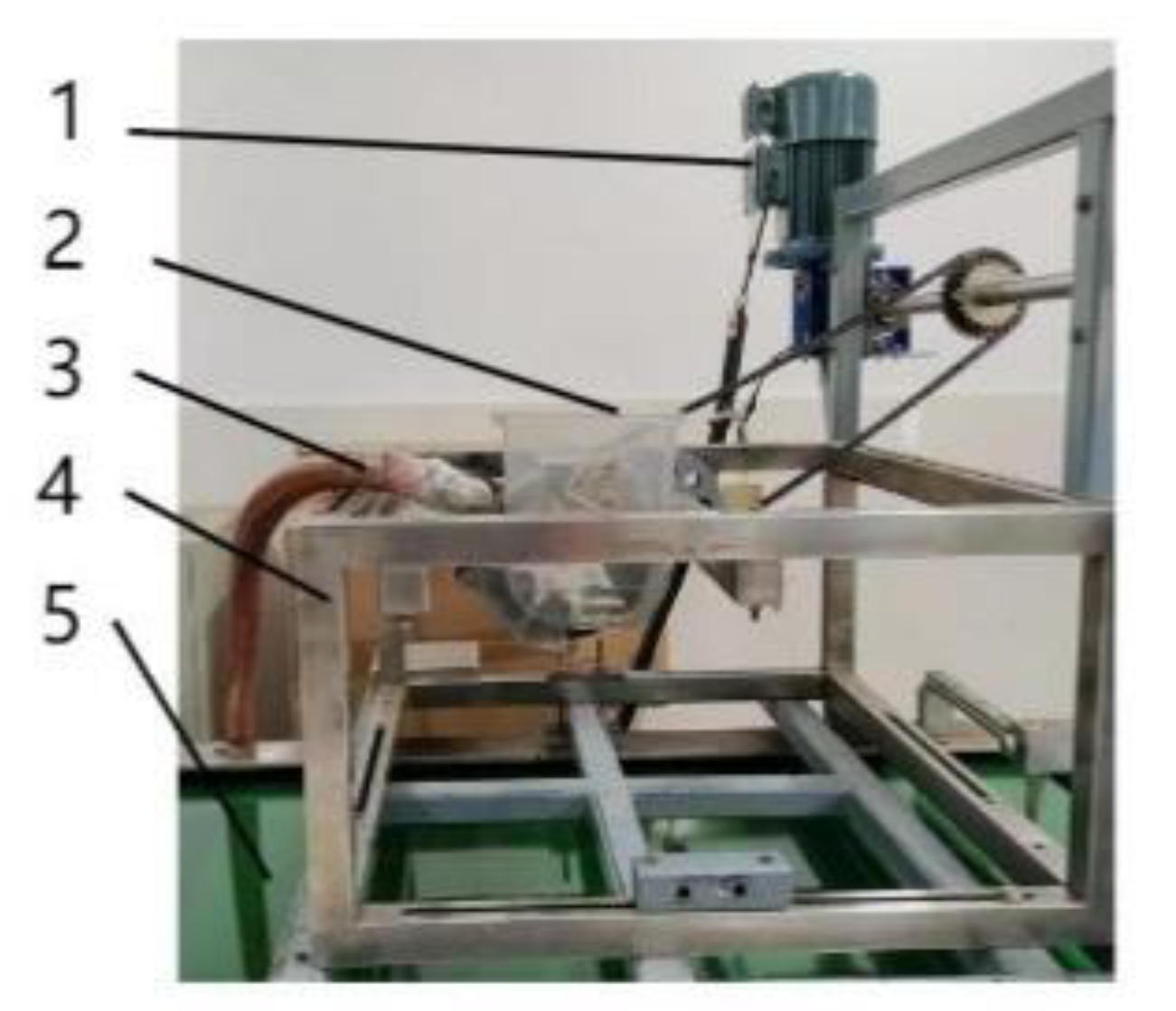
Figure 14.
The impacts of interaction factors on the qualified index. (a). AB Interaction; (b). AC Interaction; (c). BC Interaction.
Figure 14.
The impacts of interaction factors on the qualified index. (a). AB Interaction; (b). AC Interaction; (c). BC Interaction.

Figure 15.
The impacts of interaction factors on the multiple index. (a). AC Interaction; (b). BC Interaction.
Figure 15.
The impacts of interaction factors on the multiple index. (a). AC Interaction; (b). BC Interaction.
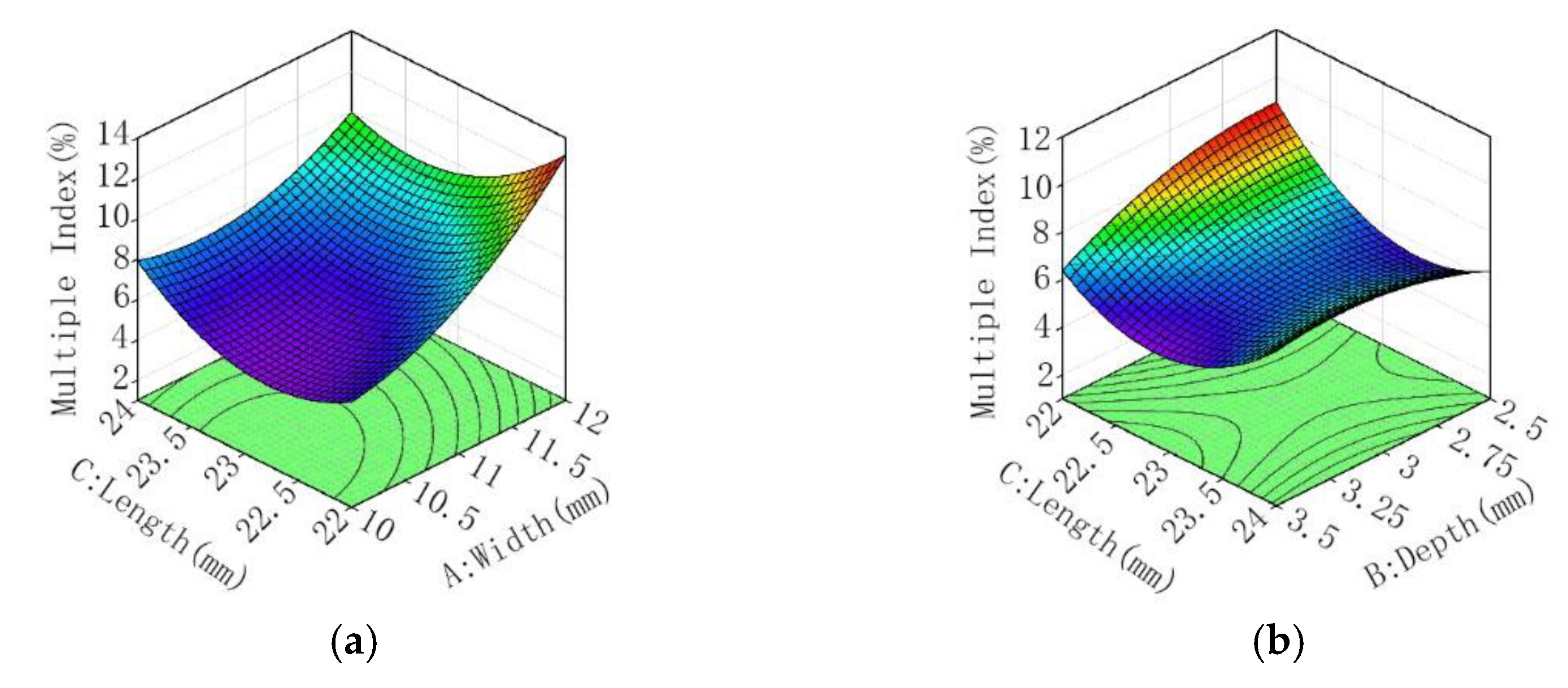
Figure 16.
The impact of interaction factors on the miss index.

Table 1.
Triaxial size of sunflower seeds.
| Arguments | Length (mm) | Width (mm) | Thickness (mm) |
|---|---|---|---|
| Maximum | 20.04 | 9.61 | 5.92 |
| Average value | 16.93 | 7.56 | 4.23 |
| Minimum | 13.32 | 5.42 | 2.56 |
| Coefficient of variation | 7.6% | 10.1% | 15.6% |
Table 2.
Coding of test factors.
| Level Code | Factors | ||
|---|---|---|---|
| Groove Width A/(mm) | Groove Depth B/(mm) | Groove Length C/(mm) | |
| 1 | 10 | 2.5 | 22 |
| 0 | 11 | 3 | 23 |
| −1 | 12 | 3.5 | 24 |
Table 3.
Experimental design and results.
| Test Serial Number | Factors | Evaluation Indicators | ||||
|---|---|---|---|---|---|---|
| A | B | C | Qualified Index Y1 (%) | Multiple Index Y2 (%) | Miss Index Y3 (%) | |
| 1 | 1 | 0 | 1 | 86.38 | 10.82 | 2.80 |
| 2 | 1 | 1 | 0 | 86.92 | 8.30 | 4.78 |
| 3 | 1 | −1 | 0 | 84.16 | 9.38 | 6.46 |
| 4 | 1 | 0 | −1 | 82.43 | 13.55 | 4.02 |
| 5 | −1 | 0 | −1 | 89.94 | 5.40 | 4.66 |
| 6 | 0 | −1 | −1 | 86.34 | 9.15 | 4.51 |
| 7 | 0 | 1 | −1 | 89.61 | 6.60 | 3.79 |
| 8 | −1 | −1 | 0 | 90.35 | 4.58 | 5.07 |
| 9 | −1 | 1 | 0 | 88.42 | 4.19 | 7.39 |
| 10 | 0 | 0 | 0 | 90.35 | 6.55 | 3.10 |
| 11 | 0 | 0 | 0 | 91.44 | 5.48 | 3.08 |
| 12 | 0 | 0 | 0 | 90.74 | 5.85 | 3.41 |
| 13 | 0 | 1 | 1 | 88.27 | 7.28 | 4.45 |
| 14 | −1 | 0 | 1 | 87.06 | 7.50 | 5.44 |
| 15 | 0 | −1 | 1 | 89.79 | 6.13 | 4.08 |
Table 4.
Analysis of variance for the qualified index.
| Evaluation Indicators | Source | Sum of Squares | df | Mean Square | F-Value | p-Value | Significance |
|---|---|---|---|---|---|---|---|
| Qualified Index | Model | 92.19 | 9 | 10.24 | 58.05 | 0.0002 | ** |
| A | 31.52 | 1 | 31.52 | 178.63 | <0.0001 | ** | |
| B | 0.832 | 1 | 0.832 | 4.72 | 0.082 | ||
| C | 1.26 | 1 | 1.26 | 7.16 | 0.044 | * | |
| AB | 5.5 | 1 | 5.5 | 31.16 | 0.0025 | ** | |
| AC | 11.66 | 1 | 11.66 | 66.09 | 0.0005 | ** | |
| BC | 5.74 | 1 | 5.74 | 32.51 | 0.0023 | ** | |
| A2 | 27.23 | 1 | 27.23 | 154.28 | <0.0001 | ** | |
| B2 | 1.63 | 1 | 1.63 | 9.26 | 0.0286 | * | |
| C2 | 10.36 | 1 | 10.36 | 58.73 | 0.0006 | ** | |
| Residual | 0.8823 | 5 | 0.1765 | ||||
| Lock of fit | 0.2722 | 3 | 0.0907 | 0.2975 | 0.8286 | ||
| Pure Error | 0.6101 | 2 | 0.305 | ||||
| Cor Total | 93.07 | 14 |
Note: * indicates significant difference (0.01 ≤ p < 0.05); ** indicates highly significant difference (p < 0.05).
Table 5.
Analysis of variance for the multiple index.
| Evaluation Indicators | Source | Sum of Squares | df | Mean Square | F-Value | p-Value | Significance |
|---|---|---|---|---|---|---|---|
| Multiple Index | Model | 86.88 | 9 | 9.65 | 27.18 | 0.001 | ** |
| A | 51.92 | 1 | 51.92 | 146.17 | <0.0001 | ** | |
| B | 1.03 | 1 | 1.03 | 2.9 | 0.1494 | ||
| C | 1.1 | 1 | 1.1 | 3.1 | 0.1384 | ||
| AB | 0.119 | 1 | 0.119 | 0.3351 | 0.5878 | ||
| AC | 5.83 | 1 | 5.83 | 16.42 | 0.0098 | ** | |
| BC | 3.42 | 1 | 3.42 | 9.64 | 0.0267 | * | |
| A2 | 6.63 | 1 | 6.63 | 18.67 | 0.0076 | ** | |
| B2 | 1.75 | 1 | 1.75 | 4.91 | 0.0775 | ||
| C2 | 15.03 | 1 | 15.03 | 42.31 | 0.0013 | ** | |
| Residual | 1.78 | 5 | 0.3552 | ||||
| Lock of fit | 1.19 | 3 | 0.3951 | 1.34 | 0.4547 | ||
| Pure Error | 0.5906 | 2 | 0.2953 | ||||
| Cor Total | 88.65 | 14 |
Note: * indicates significant difference (0.01 ≤ p < 0.05); ** indicates highly significant difference (p < 0.05).
Table 6.
Analysis of variance for the miss index.
| Evaluation Indicators | Source | Sum of Squares | df | Mean Square | F-Value | p-Value | Significance |
|---|---|---|---|---|---|---|---|
| Miss index | Model | 21.68 | 9 | 2.41 | 15.49 | 0.0038 | ** |
| A | 2.53 | 1 | 2.53 | 16.28 | 0.01 | * | |
| B | 0.0105 | 1 | 0.0105 | 0.0676 | 0.8052 | ||
| C | 0.0055 | 1 | 0.0055 | 0.0354 | 0.8581 | ||
| AB | 4 | 1 | 4 | 25.72 | 0.0039 | ** | |
| AC | 1 | 1 | 1 | 6.43 | 0.0522 | ||
| BC | 0.297 | 1 | 0.297 | 1.91 | 0.2255 | ||
| A2 | 6.99 | 1 | 6.99 | 44.92 | 0.0011 | ** | |
| B2 | 6.76 | 1 | 6.76 | 43.46 | 0.0012 | ** | |
| C2 | 0.4321 | 1 | 0.4321 | 2.78 | 0.1564 | ||
| Residual | 0.7775 | 5 | 0.1555 | ||||
| Lock of fit | 0.7091 | 3 | 0.2364 | 6.9 | 0.1291 | ||
| Pure Error | 0.0685 | 2 | 0.0342 | ||||
| Cor Total | 22.46 | 14 |
Note: * indicates significant difference (0.01 ≤ p < 0.05); ** indicates highly significant difference (p < 0.05).
Table 7.
Results of the verification experiments.
| Number | Qualified Index | Multiple Index | Miss Index |
|---|---|---|---|
| 1 | 90.04 | 6.21 | 3.75 |
| 2 | 93.16 | 4.76 | 2.08 |
| 3 | 91.68 | 5.92 | 2.40 |
| Average value | 91.63 | 5.63 | 2.74 |
Disclaimer/Publisher’s Note: The statements, opinions and data contained in all publications are solely those of the individual author(s) and contributor(s) and not of MDPI and/or the editor(s). MDPI and/or the editor(s) disclaim responsibility for any injury to people or property resulting from any ideas, methods, instructions or products referred to in the content. |
© 2022 by the authors. Licensee MDPI, Basel, Switzerland. This article is an open access article distributed under the terms and conditions of the Creative Commons Attribution (CC BY) license (https://creativecommons.org/licenses/by/4.0/).
Share and Cite
MDPI and ACS Style
Zhao, X.; Zhang, T.; Liu, F.; Li, N.; Li, J. Sunflower Seed Suction Stability Regulation and Seeding Performance Experiments. Agronomy 2023, 13, 54. https://doi.org/10.3390/agronomy13010054
AMA Style
Zhao X, Zhang T, Liu F, Li N, Li J. Sunflower Seed Suction Stability Regulation and Seeding Performance Experiments. Agronomy. 2023; 13(1):54. https://doi.org/10.3390/agronomy13010054
Chicago/Turabian StyleZhao, Xuan, Tao Zhang, Fei Liu, Na Li, and Junru Li. 2023. "Sunflower Seed Suction Stability Regulation and Seeding Performance Experiments" Agronomy 13, no. 1: 54. https://doi.org/10.3390/agronomy13010054
Note that from the first issue of 2016, this journal uses article numbers instead of page numbers. See further details here.