Article

Novel Procedure for Designing and 3D Printing a Customized Surgical Template for Arthrodesis Surgery on the Sacrum

1
Department of Industrial Engineering, University of Salerno, 132, 84084 Fisciano, Italy
2
I.M.C.A.R. S.P.A., Via Salvo d’Acquisto 49, 20863 Concorrezzo MB, Italy
*
Author to whom correspondence should be addressed.
Symmetry 2018, 10(8), 334; https://doi.org/10.3390/sym10080334
Submission received: 10 July 2018 / Revised: 5 August 2018 / Accepted: 7 August 2018 / Published: 10 August 2018
(This article belongs to the Special Issue Symmetry and Engineering Design)

Abstract

:
In this article, the authors propose a novel procedure for designing a customized 3D-printed surgical template to guide surgeons in inserting screws into the sacral zone during arthrodesis surgeries. The template is characterized by two cylindrical guides defined by means of trajectories identified, based on standard procedure, via an appropriate Computer-Aided-Design (CAD)-based procedure. The procedure is based on the definition of the insertion direction by means of anatomical landmarks that enable the screws to take advantage of the maximum available bone path. After 3D printing, the template adheres perfectly to the bone surface, showing univocal positioning by exploiting the foramina of the sacrum, great maneuverability due to the presence of an ergonomic handle, as well as a break system for the two independent guides. These features make the product innovative. Thanks to its small size and the easy anchoring, the surgeon can simply position the template on the insertion area and directly insert the screws, without alterations to standard surgical procedures. This has the effect of reducing the overall duration of the surgery and the patient’s exposure to X-rays, and increasing both the safety of the intervention and the quality of the results.

1. Introduction

Screw placement in spinal segments is a frequently used procedure for posterior stabilization of the spine [1,2] via arthrodesis intervention [3]. The variability of pedicles’ geometries and orientation, their small size, as well as the existence of nearby nerve roots and vascular structures can cause problems for screw placement.
This paper focuses on interventions in the lower back area, in particular the sacrum [4,5]. Arthrodesis surgeries in the sacral zone are made in cases of spinal deformity, as well as in cases of fracture [6]. The most common surgeries use screws and rods. The screws are inserted into the bone structures and locked by means of connecting bars. Screws with cement augmentation are sometimes used to enhance stability [7,8]. Generally, this type of intervention is manually executed, and results are hence significantly dependent on the experience of the surgeon. In addition, the risks of incorrect positioning of the screws, as well as risks related to the radiation dose, appear high. Other techniques characterized by greater precision but also by huge complexity and costs are available [9,10]. A solution to these problems is the use of a patient-specific template. Bibb et al. describe the advantages of using rapid prototyping for manufacturing patient-specific drill guides (e.g., stereo lithography) [11].
The accurate placement of screws inside the spine has always been a very difficult aspect of arthrodesis surgeries. The standard arthrodesis procedure consists in etching the area of intervention, opening it with the use of appropriate retractors, and bringing the bone tissue to light moving/removing of most of the organic tissues that cover the area. In this case, the bone tissue is covered by the joints and muscles and is not, therefore, directly visible. The surgeon then prepares the screw access via two awls: an opening awl, required to open the cortical bone; and a depth awl to build the canal, featuring markers at different lengths. The definition of the screw channel is made via an iterative process characterized by several X-rays, the outcome of which is highly dependent on the experience of the surgical team. The surgeon then measures the length of the channel generated using an appropriate probe to determine the length of the screw. The insertion of the screws is normally done manually with a special screwdriver and by exploiting the previously prepared channel. Once inserted, the screws are connected together with bars. The choice of the entry point for the screws and the direction of the insertion are the two key problems encountered during these kinds of surgeries. Once the entry point is fixed, surgeons generally need to make adjustments or corrections to the direction of the screws. The incorrect positioning of the screws may lead to an increase in the overall duration of surgery, and, consequently, more harmful, real-time X-ray checks [1,2] and can cause operating failures and subsequent re-operations,. Computer-Aided Surgery (CAS) uses systems that provide real-time assistance to the surgeon during the operation. The key technique of CAS methodology is surgical navigation that allows the surgeon to operate in a minimally invasive way, with a reduction in unnecessary movements and an increase in accuracy. However, there are also considerable disadvantages: the high cost of the equipment; exposure to radiation; the need of additional staff. Moreover, from a technical perspective, the calibration process is very complicated and an incorrect final positioning of the patient might lead to imprecision [2]. The use of patient-specific surgical templates for guiding the screws inside the bone tissue is a valid alternative to the described methodologies. The literature reports two different approaches for designing a patient-specific template. The first approach is to consider the shape of the guide as a negative of the vertebra bone surface [12,13,14]. The second approach uses supports affixed to the transverse process, the spinous process, and/or the lamina [15,16,17,18]. Regarding the preoperative definition of the ideal screw direction, most of the studies are based on the prior identification by the surgeon [19,20] and in a few works [21,22,23,24,25] the authors determine a predefined best pedicle screw trajectory and/or diameter and maximum screw length. Few studies have focused on the improvement and optimization of arthrodesis surgery conducted on the sacral zone of the spine by means of a template to guide the screws inside the bone. Mazda et al. (1998) [26] in the context of the Jackson intrasacral fixation designed a template for the safe positioning of transpedicular endplate screws by determining a ‘cylinder of safety’. The efficiency of the device is yet to be confirmed by anatomic and clinical studies. Zhang et al. (2009) [27] proposed 3D printed template design for the fixation of sacral fractures based on the anatomic features of the posteroiliac section and the channel. Ryan et al. (2013) [28] patented a patient-specific alignment guide including a patient-specific portion and a guiding element with a through opening for sacroiliac fixation. Chen et al. (2012) [29] designed a personalized image-based template for patients with unstable pelvic ring fractures which showed better correct screw positions, reduced radiation exposure, and shorter surgery time compared with the conventional fluoroscopy-based surgeries. Merc et al. (2013) [30] performed a clinical study on the manufacture of templates for the lumbar and sacral regions that enable the implantation of simultaneous multiple-level screws, evaluating also the error rate [31]. Éltes et al. (2016) [32] created a template for sacrum with two screw-guiding structures using photoactive 3D printing technology. Merc et al. (2017) [33] concluded that although the template for sacral pedicle screw placement does not reduce pain and disability than the free-hand technique, however, does reduce the incidence of cortex perforation.
In light of this evidence, a drill guide is still an additional tool that could potentially compete with other screw placement techniques in the future.

2. Purpose

The goal of this work is to create an ad hoc surgical template for the sacrum using rapid prototyping methods. A novel procedure designed to pre-plan the screw insertion trajectories in the sacrum is proposed. These trajectories are defined by means of a Computer Aided Design (CAD) model of the insertion area obtained through appropriate reverse engineering techniques. Even the length and diameter of the screws can be chosen appropriately. In addition, the proposed shape and the anchorage system make the template placement univocal and comfortable, avoiding incorrect relative positioning between the template and the sacrum. In this way, the surgeon can apply the patient-specific template quickly and safely to the area of intervention and insert the screws without changing the standard surgery procedure.

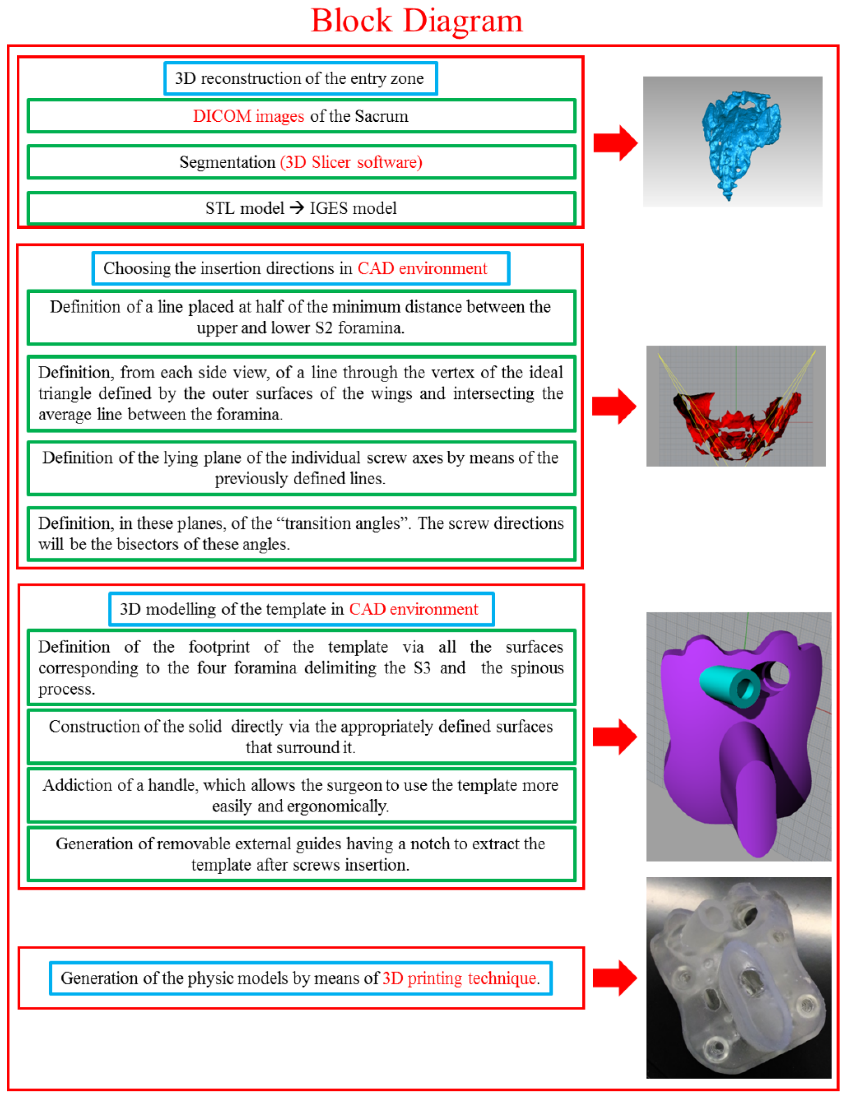
3. Materials and Methods

CAD/CAM (Computer Aided Manufacturing) software are widely used in the biomedical field both for the reconstruction of bone scaffolds and devices from DICOM (Digital Imaging and COmmunications in Medicine) images and in their design and manufacture [25,34,35,36]. The proposed procedure involves the following steps (see Figure 1): 3D reconstruction of the entry zone; determination of the screw insertion directions; 3D modelling of the template; physical production of the template model.

3.1. 3D Reconstruction of the Entry Zone

From DICOM images obtained by CT (Computerized Tomography) scans of the sacral zone, and using 3D Slicer open-source software (Slicer 4.8 released; https://www.slicer.org/), the entire sacrum and some parts of L5 and the iliac bones are segmented to define the boundaries of a possible area for a dorsal application of the template. The STL (Solid To Layer) model corresponding to the segmented areas is rebuilt using the same software. The STL model is then transformed into an IGES (Initial Graphics Exchange Specification) model using Geomatics software (by 3D Systems, 333 Three D Systems Cir. Rock Hill, SC 29730, USA). The IGES model is defined by surfaces, allowing small areas of the sacrum to be analyzed using CAD software. Then, the 3D reconstruction is imported into Rhinoceros modelling software (by Robert McNeel & Associates, 3670 Woodland Park Ave N Seattle, WA 98103, USA). Coronal, sagittal, and transverse planes, that are the characteristic planes of the human body, are considered coincident with those of the CT scans.

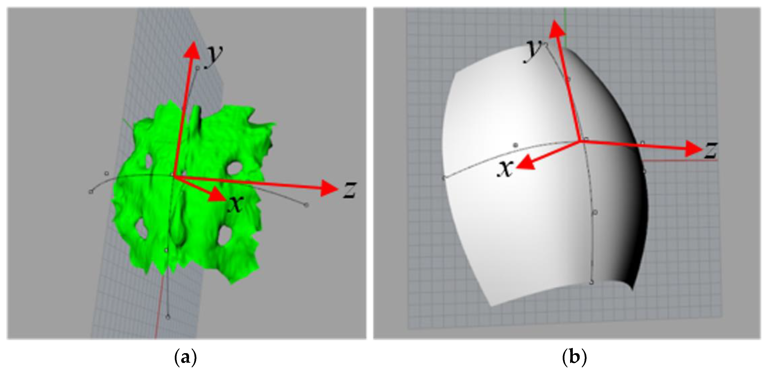
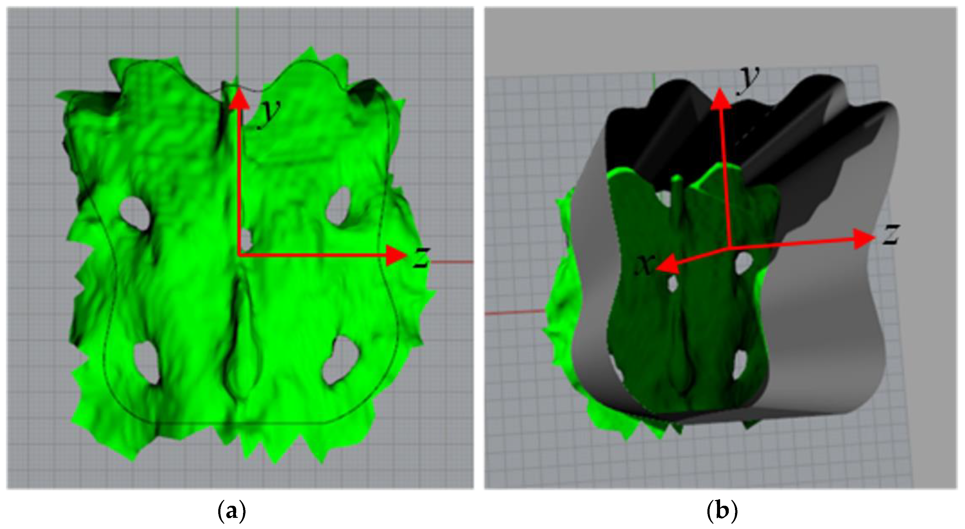
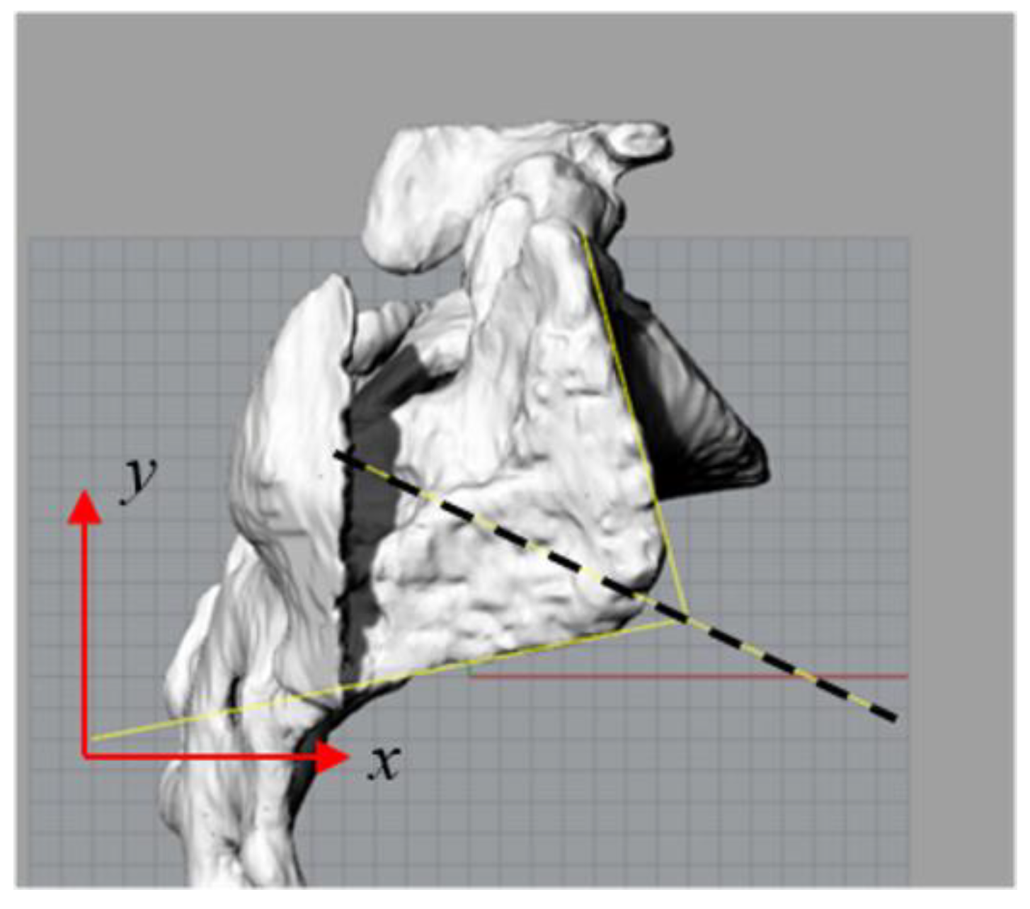
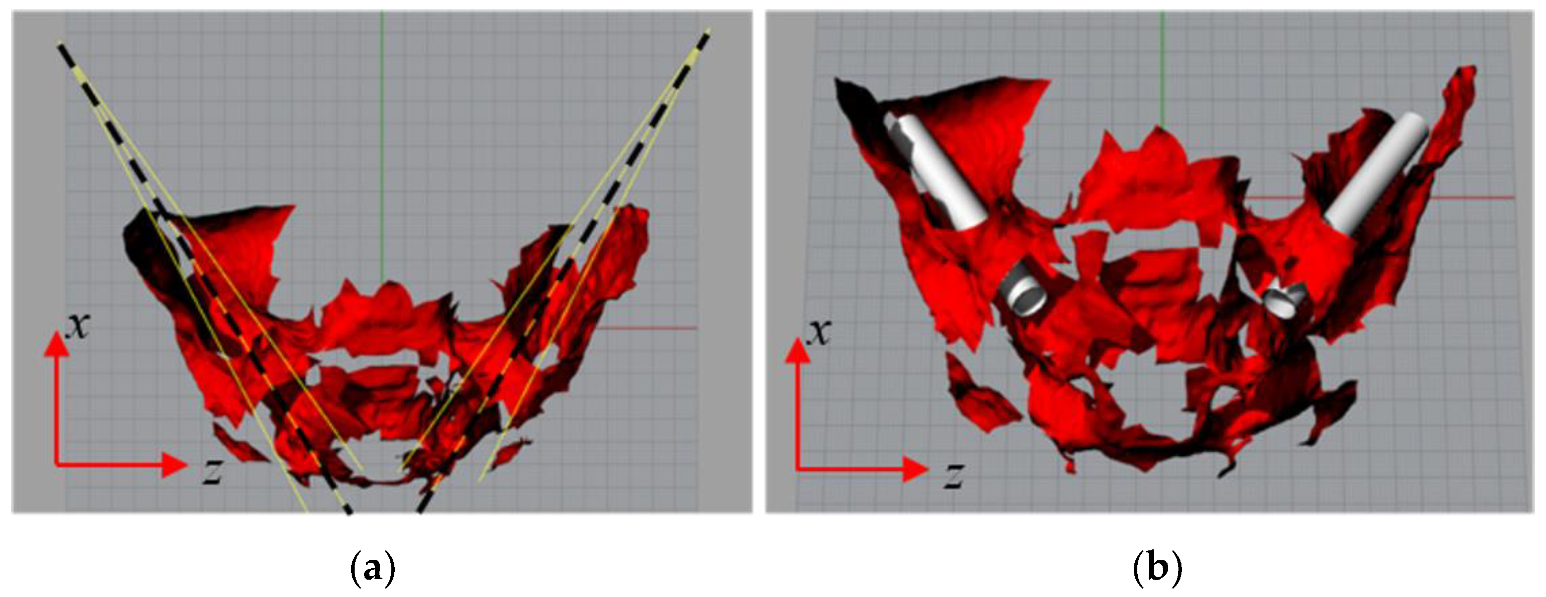
3.2. Procedure for Determining the Insertion Directions

In the sacral zone, the screws are normally inserted into S1 or S2, and can be oriented in the wings or in the vertebral body. The first of these involves alar screws; the second, pedicle screws. The entry point of the screws in S2 (S2-alar screws) [37] is located and routed along the wings. In this way, it is possible to employ a wider area that is free from obstacles compared to S1, which is characterized, conversely, by the presence of some L5 structures. Moreover, thanks to the direction along the wings, a greatest volume of bone is available, which facilitates anchoring. In some tests, S2 alar screws resulted in more stability than the more frequently used S1 pedicle screws [38,39]. The structures that the screw does not have to overcome are [40]:
  • The external surface of the sacrum, as the sacrum-iliac joint could be laterally damaged, resulting in the appearance of pain. Dorsally, the sacral nerves protruding from the foramina could also be damaged;
  • The interiors canaliculi that connect the dorsal and ventral foramina in which the sacral nerves are located;
  • The surface delimiting the sacral canal that contains the sacral nerves.
In the CAD environment, a plane is appropriately positioned to be sufficiently frontal to the foramina that delimit S2. On this level, an average line between the foramina is defined. This line is placed at half of the minimum distance between the upper and lower S2 foramina. From each side view, a line through the vertex of the ideal triangle defined by the outer surfaces of the wings, and intersecting the average line, as defined above, in the middle point between the foramina (see Figure 2) is drawn. The lying plane of the individual screw axes is defined by the combination of the average line between the foramina and the single line passing through the vertex of the triangle (see Figure 2). Based on the classical surgical procedure, the identified direction enables the screw to take advantage of the maximum available bone path, which is crucial to facilitate anchoring. The protection of the channels, which connect the foramina, is ensured by choosing the average line between them. In these planes, the screws’ “transition angles” are defined through the lines tangential to the sacral canal on one side and the wing outer surface on the other. The bisectors of the defined angles are generated, and these represent the screw directions (see Figure 3). The diameter and length of the screws depend on the anatomy of the sacrum, the application of the screw, and the screw supplier. Generally, for these applications, diameters ranging from 6–8 mm are used. Screws of 7 mm diameter were evaluated here, and no surface-breakings of any kind (see Figure 3) were observed. Furthermore, staying too far from the outer surface does not allow the bone cortical layer (extremely hard tissue which favors the anchorage) to be used.

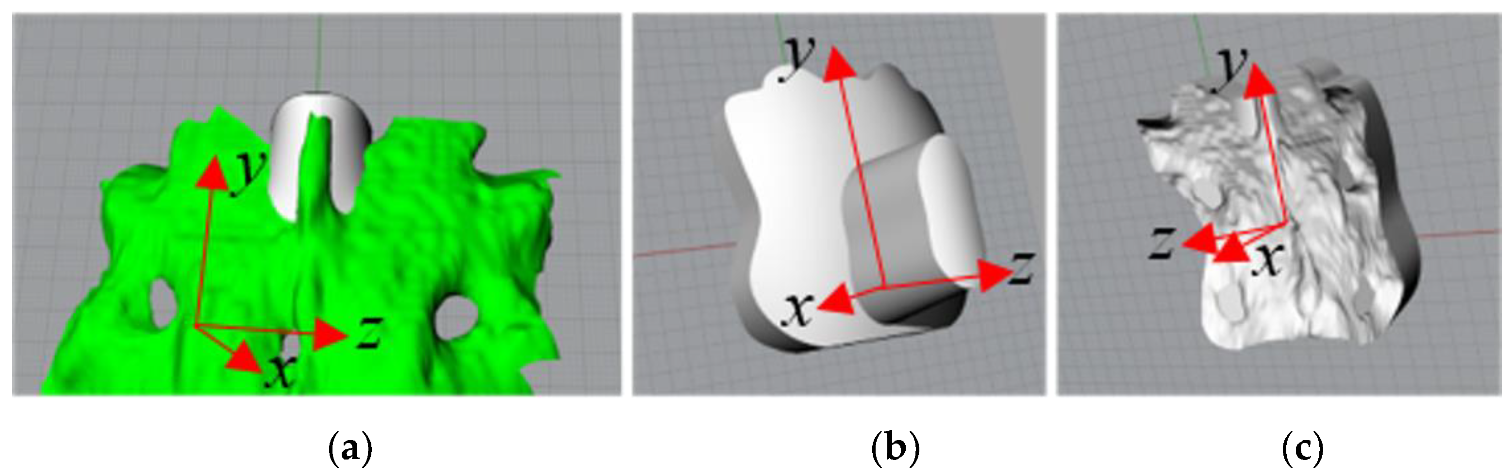
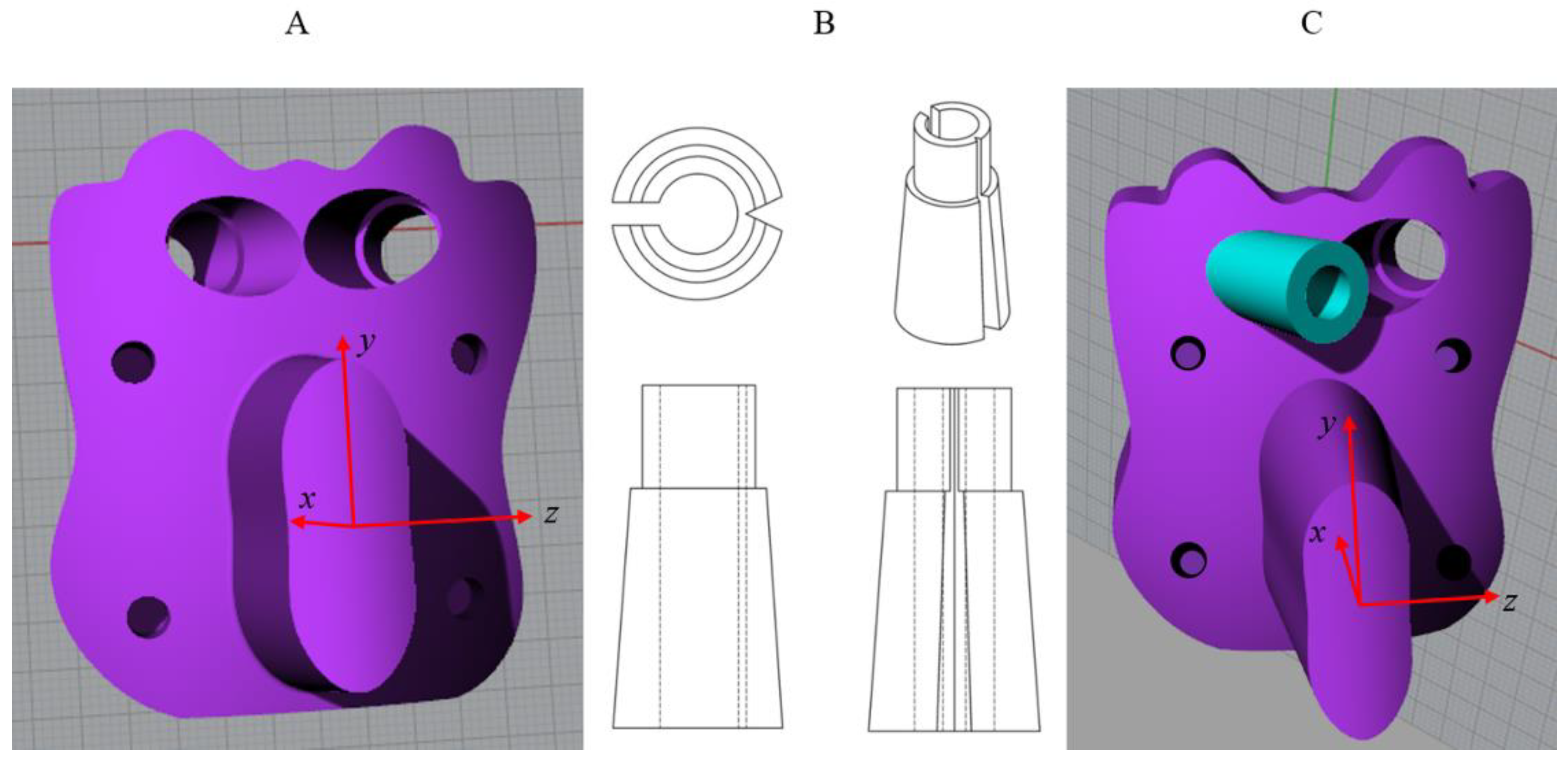
3.3. 3D Modelling of the Template

The proposed procedure prescribes the use of rear holes (foramina) of the sacrum for the univocal template anchorage. In this specific case, the four foramina delimiting S3 and the spinous process function as a hold (four points are generally ideal for stable positioning, which is further encouraged by the central support of the spinous process [25]). The footprint of the template is, therefore, defined via all the surfaces that comprise it. These surfaces are then moved to a separate layer. The solid is obtained via poly surfaces’ offset derived by 3D patch of the outer surface of the sacrum to be covered with the template. Different surfaces, which delimit the template, are therefore defined. First, the footprint foramina is closed using circular flat surfaces so that the template does not excessively penetrate them, to avoid colliding with nerve bundles. The upper surface of the template is modelled by the sweep of a second-degree curve. This curve is drawn on a sagittal plane directed symmetrically to the base surface. The direction of the sweep is defined using another parabolic curve lying on a plane orthogonal to the preceding plane (see Figure 4). These surfaces are joined through a prism the base of which defines exactly the shape the template will connect to the sacrum. The base is extruded in a direction such that the resulting surface is sufficiently (between 85° and 95°) orthogonal to the bearing surface of the template (see Figure 5). Blank areas between the spinous process and the surface of the sacrum, which arise during the procedure, are filled by appropriately designed loft surfaces (see Figure 6). With the guidance of expert surgeons, a handle is added, which allows the surgeon to use the template more easily and ergonomically. The handle is placed as low as possible not to interfere with the insertion of the screws. Finally, by means of CAD software suitable for surface and freeform modelling (e.g., Rhinoceros) automatically reconstructs the closed solid, the boundaries of which are defined by intersecting surfaces defined above (see Figure 6). From DICOM images obtained by CT scans of the sacral zone, and using 3D Slicer open-source software, the entire sacrum and some parts of L5 and the iliac bones are segmented to define the boundaries of a possible area for a dorsal application of the template. The STL model corresponding to the segmented areas is rebuilt using the same software. The STL model is then transformed into an IGES model using Geomagic software. The IGES model is defined by surfaces, allowing small areas of the sacrum to be analyzed using CAD software. Then, the 3D reconstruction is imported into Rhinoceros modelling software. CT scans planes have been considered coincident with human body’s characteristic planes.
The screws haves heads with diameters larger than the shank ones. The template must guide the insertion of the screw and then move away from the application zone. To achieve this, the template is bored with a diameter of 10 mm along the directions of the screws, assuming that the screw head has a smaller diameter (see Figure 7A). The template is then bored further with a circular section of a slightly larger diameter. However, this drilling, unlike in the previous instance, does not pass all the way through; rather, it is intended to create a flat support for the future external guides. The drilling is also not straight but tapered at a 1.5 degree angle to facilitate the insertion of the external guide (see Figure 7A). Using the internal guides defined previously, the external guides are then generated. These are partly conical and partly cylindrical, with an internal diameter equal to that of the screw (see Figure 7B). Next, the guides are inserted into the holes in the template until they reach their limit (see Figure 7C). For the successful insertion of the screw, the stabilizing guide should be of an appropriate length. This, together with the inclination of the screws, does not allow two guides to be simultaneously inserted in the template. This is not a problem, however, as individual insertion does not affect the operation. The surgeon has to insert the screw to a certain distance so that it generates its own guide inside the bone. The guide then rises along the shank of the screw and is either deformed or broken due to a notch formed on the outer surface of the screw and a specific non-complete section of the guide (see Figure 7B). After removing the guide, the final insertion of the screw is achieved by exploiting the bony canal generated previously. Small holes used as a drilling section on the upper surface of the template for a certain depth are generated. These correspond with the circular surfaces used to close the openings of the template base, which correspond with the foramina. In this way, the surgeon is able to physically locate the position of the four dorsal foramina (see Figure 7A,C).

3.4. 3D Reconstruction of the Entry Zone

From DICOM images obtained by CT scans of the sacral zone, and using 3D Slicer open-source software, the entire sacrum and some parts of L5 and the iliac bones are segmented to define the boundaries of a possible area for a dorsal application of the template. The STL model corresponding to the segmented areas is rebuilt using the same software. The STL model is then transformed into an IGES model using Geomagic software. The IGES model is defined by surfaces, allowing small areas of the sacrum to be analyzed using CAD software. Then, the 3D reconstruction is imported into Rhinoceros modelling software. In addition for this modelling, CT scan planes and human body planes have been aligned (coincident).

3.5. Error Chain Analysis

Each modelling step may introduce errors due to modelling features (like approximating geometries or IGES vs. STL format), to designer’s errors and to reconstruction errors. In order to check the reliability and the precision of the final model for Rapid Manufacturing, several measures have been taken on the original DICOM file using the measuring tools that are available in the MiView™ Software (NITRC, Washington, DC, USA). Main dimensions and distance between anatomical parts (like foramina, wings’ width, sacral canal width, etc.) have been used for a randomized check of measures and the error was always under 0.7 mm, to be considered more than acceptable based on the excellent results of the bone-template coupling tests made on the printed specimens that will be discussed later. An error-checking protocol has not yet been developed.

3.6. Generation of the Template

Once modelled, the template can be easily generated through rapid prototyping. Biocompatible materials must be used to build the template, since it will be in contact with the internal structures of the body. A prototype was created to evaluate the characteristics of the template and its functionality. Stereolithography (SLA) technique (Form 2 by Formlabs, Formlabs Inc. 35 Medford St. Suite 201. Somerville, MA 02143 USA) was utilized to generate the template and the left guide (see Figure 8A,B) using a biocompatible resin (Dental SG, Class 1 biocompatible resin (EN-ISO 10993-1:2009/AC: 2010, USP Class VI) designed to directly print surgical and pilot drill guides). 3D printing was realized with a layer thickness of 0.05 mm. The supports were automatically generated in such a way that they do not appear on the contact surface characterizing the bone-template coupling. After 3D printing the model was immersed in 95% isopropyl alcohol (IPA) for 20 min to remove residues and subsequently, after drying at room temperature, it was postcured in a UV oven for 20 min to complete the polymerization (the resin is autoclavable for in vivo tests). The template was generated in 4 h (Form 2 does not allow the printing speed to be set). The process was carried out without problems, resulting in a template that is light, practical, and pleasantly ergonomic to use. Regarding the guide, an outside diameter equal to that of the inner rails of the template was assigned, in the event the material experienced dimensional shrinkage after processing [25]. This, along with its tendency to wear out easily, justifies the choice. The insertion of the guide into the template, repeated several times, obtains a smooth and very stable coupling due to wear by friction, which improves operational safety. To evaluate the coupling of the model with the surface of the sacrum, the portion of the sacrum in contact with the template was created using Fused Filament Fabrication (FFF) technique (Sharebot by Sharebot S.r.l., Via Montello, 18, 23895 Nibionno (LC)) by using ABS (Acrylonitrile Butadiene Styrene) material (see Figure 8C,D). Errors introduced by 3D printing can be controlled and are always under 0.5 mm; the proof of this is given by the perfect match between two solids realized with two different 3D printing technologies.

4. Discussion

The approach presented in this work does not modify the standard procedure, and does not require expensive equipment as, for example, is the case with navigation systems. On average, the cost of a surgical navigation system is €85,000 per year (instrumentation amortization and specialized personnel). In Italy, approximately 50,000 spinal fusion procedures take place annually. On average about 50 operations take place per year for each surgical structure [41]. A rough estimate of the costs resulted in a cost of €500 (raw materials, specialized personnel, equipment, etc.) per surgical operation using the surgical template and, as a result, an average of €25,000 per year for the surgical structure [41]. Moreover, the approach presented in this work does not force the patient and the surgical staff to long imaging sessions with the consequent high doses of radiation. The procedure consists in etching and opening the screw insertion area, skeletonising the underlying structures of interest (operations prescribed by standard procedure), and applying a template that allows the screw insertion to be drilled directly into the bone surface. The surgeon simply applies the template to the bone surface and inserts the screws. The template will anchor easily and securely to the bone, and the directions of the screws will both facilitate the anchoring of screws to the internal bone tissue and not damage the extremely delicate structures around the sacrum. The main disadvantages of this approach are the strong bleeding, the considerable invasiveness, and the high risk of infection that can lead to very serious consequences if the patient is suffering from other pathologies. After the generation of the support and the template, the coupling between the surface of the sacrum and the template is not only stable but also very simple to achieve manually, enhancing the ease of the operation. The template is very compact, which makes for ease of handling and, consequently, a successful intervention. Furthermore, it allows for the incision and the opening to be minimized, reducing the invasiveness. Two common rapid prototyping technologies were used and compared. Both allow for the generation of complex geometries. However, the SLA obtains a better surface quality than the FFF, despite its longer processing times. From the reception of the CT scans to the realization of the 3D printed physical model an average time of 8 h has been calculated. The estimated errors are always under 1.2 mm; this value is fully compatible with surgery of the sacrum—in the opinion of the expert surgeons that were consulted—and is very low if compared with the potential errors due to the equivalent manual insertion of the screws.

5. Conclusions

In this work, the authors tried to improve surgical arthrodesis in the sacral area, defining a possible alternative methodology that was not in conflict with conventional techniques. A template design procedure was conceived, which, after appropriate skeletisation of the intervention zone, can be applied to the dorsal face of S2 and S3 and drive the insertion of the screws in the sacrum. To avoid damaging delicate structures and to facilitate the anchoring of the screws, it was necessary to assess the trajectory of the screws via CAD modelling of the sacrum. The procedure is based on the definition of the insertion direction by means of anatomical landmarks that enable the screws to take advantage of the maximum available bone path, which is crucial to facilitate anchoring. Moreover, the product can be considered innovative due to the perfect adherence of the device with the bone surface, the univocal positioning determined by exploiting the holes present on the sacrum (foramina), the maneuvrability of the device determined by the presence of the handle, as well as the break system of the independent guides. This approach avoids the high costs and the high doses of ionizing radiation associated with surgical navigation, which is currently considered the most appropriate technique for arthrodesis interventions [25]. A long operation duration, difficulties associated with the iterative nature of manual techniques, and all risks related to these, are also avoided. By exploiting the potential of virtual design and rapid prototyping, a fully defined and cheap device based on individual patient characteristics can be appropriately generated. The physical production of the template was performed using stereolithography. The surgical template appears very comfortable to use and the insertion of the left guide, produced using the same technology, does not require any special methods. The coupling between the template and a support, generated via FFF, was also assessed, reproducing the surface of the sacrum to which the template is applied. According to experienced surgeons who supported the authors during the development of the device, the resultant coupling was very stable and simple to achieve. One limitation of this approach is the lack of an error-protocol checking for the 3D-modeling/3D-printing operations; this has to be developed in order to assure the precision of the template both for coupling it on the sacrum bone and for identifying the correct direction for screw insertion. Future developments in this field of research should include the experimental validation of the described surgical device via in vivo testing as reported in a previous work [25], an appropriate analysis of bone density (Hounsfield unit) and the automatization of the procedure by means of an algorithm, written in the CAD environment, that is able to create a virtual model of the template with the optimal directions, thereby allowing users to prototype it directly by means of a 3D printer.

Author Contributions

The authors declare that they gave the same contribution in developing the research and assessing the results. Conceptualization, A.N.; Methodology, F.N.; Software, E.C. and R.M.; Validation, E.C and R.M.; Investigation, F.N; Writing-Original Draft Preparation, R.M. and F.N.; Writing-Review & Editing, A.N. and N.C.; Supervision, A.N.

Funding

The authors received no financial support for the research, authorship and/or publication of this article.

Acknowledgments

The authors acknowledge the support of the neurosurgeon Doctor Nicola Narciso and his staff (University Hospital “San Giovanni di Dio e Ruggi d’Aragona”, Salerno, Italy) and thank them for their advice and technical support in designing the surgical template.

Conflicts of Interest

The authors declare no potential conflicts of interest with respect to the research, authorship and/or publication of this article.

References

  1. Popescu, D.; Laptoiu, D. Rapid prototyping for patient-specific surgical orthopaedics guides: A systematic literature review. Proc. Inst. Mech. Eng. H 2016, 230, 495–515. [Google Scholar] [CrossRef] [PubMed]
  2. Popescu, D.; Anania, D.F.; Amza, C.G; Cicic, D.T. Design and rapid manufacturing of patient-specific spinal surgical guides: A survey. Proc. Manuf. Syst. 2012, 7, 2067–9238. [Google Scholar]
  3. Wang, J.C.; Mummaneni, P.V.; Haid, R.W. Current treatment strategies for the painful lumbar motion segment: Posterolateral fusion versus interbody fusion. Spine 2005, 30 (Suppl. S16), 33–43. [Google Scholar] [CrossRef]
  4. Barrey, C.Y.; Boissiere, L.; D’Acunzi, G.; Perrin, G. One-stage combined lumbo-sacral fusion, by anterior then posterior approach: Clinical and radiological results. Eur. Spine J. 2013, 22, 957–964. [Google Scholar] [CrossRef] [PubMed]
  5. Mobbs, R.J.; Phan, K.; Malham, G.; Seex, K.; Rao, P.J. Lumbar interbody fusion: Techniques, indications and comparison of interbody fusion options including PLIF, TLIF, MI-TLIF, OLIF/ATP, LLIF and ALIF. J. Spine Surg. 2015, 1, 2–18. [Google Scholar] [CrossRef] [PubMed]
  6. Wagner, D.; Ossendorf, C.; Gruszka, D.; Hofmann, A.; Rommens, P.M. Fragility fractures of the sacrum: How to identify and when to treat surgically? Eur. J. Trauma Emerg. Surg. 2015, 41, 349–362. [Google Scholar] [CrossRef] [PubMed]
  7. Tjardes, T.; Paffrath, T.; Baethis, H.; Shafizadeh, S.; Steinhausen, E.; Steinbuechel, T.; Rixen, D.; Bouillon, B. Computer assisted percutaneous placement of augmented iliosacral screws. Spine 2008, 33, 1497–1500. [Google Scholar] [CrossRef] [PubMed]
  8. Oberkircher, L.; Masaeli, A.; Bliemel, C.; Debus, F.; Ruchholtz, S.; Krüger, A. Primary stability of three different iliosacral screw fixation techniques in osteoporotic cadaver specimens—A biomechanical investigation. Spine J. 2016, 16, 226–232. [Google Scholar] [CrossRef] [PubMed]
  9. Richter, P.H.; Gebhard, F.; Dehner, C.; Scola, A. Accuracy of computer-assisted iliosacral screw placement using a hybrid operating room. Injury 2016, 47, 402–407. [Google Scholar] [CrossRef] [PubMed]
  10. Hu, X.; Lieberman, I.H. Robotic-guided sacro-pelvic fixation using S2 alar-iliac screws: Feasibility and accuracy. Eur. Spine J. 2017, 26, 720–725. [Google Scholar] [CrossRef] [PubMed]
  11. Bibb, R.; Eggbeer, D.; Evans, P.; Bocca, A.; Sugar, A. Rapid manufacture of custom-fitting surgical guides. Rapid Prototyp. J. 2009, 15, 346–354. [Google Scholar] [CrossRef] [Green Version]
  12. Van Brussel, K.; Vander Sloten, J.; Van Audekercke, R. Medical image based design of an individualized surgical guide for pedicle screw insertion. In Proceedings of the 18th Annual Conference of the IEEE Engineering in Medicine and Biology Society, Amsterdam, The Netherlands, 31 October–3 November 1996. [Google Scholar]
  13. Berry, E.; Cuppone, M.; Porada, S.; Millner, P.A.; Rao, A.; Chiverton, N.; Seedhom, B.B. Personalised image-based templates for intra-operative guidance. Proc. Inst. Mech. Eng. H 2005, 219, 111–118. [Google Scholar] [CrossRef] [PubMed]
  14. Popescu, D.; Amza, C.G.; Anania, D.; Cicic, D.T. Intelligent x-ray based training system for pedicle screw placement in lumbar vertebrae. Acad. J. Manuf. Eng. 2011, 9, 94–100. [Google Scholar]
  15. Goffin, J.; Van Brussel, K.; Martens, K.; Vander Sloten, J.; Van Audekercke, R.; Smet, M.H. Three-dimensional computed tomography-based, personalized drill guide for posterior cervical stabilization at C1-C2. Spine 2001, 26, 1343–1347. [Google Scholar] [CrossRef] [PubMed]
  16. Lu, S.; Xu, Y.Q.; Zhang, Y.Z.; Xie, L.; Guo, H.; Li, D.P. A novel computer-assisted drill guide template for placement of C2 laminar screws. Eur. Spine J. 2009, 18, 1379–1385. [Google Scholar] [CrossRef] [PubMed] [Green Version]
  17. Lu, S.; Xu, Y.Q.; Zhang, Y.Z.; Li, Y.B.; Shi, J.H.; Chen, G.P.; Chen, Y.B. Rapid prototyping drill guide template for lumbar pedicle screw placement. Chin. J. Traumatol. 2009, 12, 177–180. [Google Scholar] [PubMed]
  18. Lu, S.; Xu, Y.Q.; Chen, G.P.; Zhang, Y.Z.; Lu, D.; Chen, Y.B.; Shi, J.H.; Xu, X.M. Efficacy and accuracy of a novel rapid prototyping drill template for cervical pedicle screw placement. Comput. Surg. 2011, 16, 240–248. [Google Scholar] [CrossRef] [PubMed] [Green Version]
  19. Sugawara, T.; Higashiyama, N.; Kaneyama, S.; Takabatake, M.; Watanabe, N.; Uchida, F.; Sumi, M.; Mizoi, K. Multistep pedicle screw insertion procedure with patient-specific lamina fit-and-lock templates for the thoracic spine. J. Neurosurg. Spine 2013, 19, 185–190. [Google Scholar] [CrossRef] [PubMed] [Green Version]
  20. Kaneyama, S.; Sugawara, T.; Sumi, M. Safe and accurate midcervical pedicle screw insertion procedure with the patient-specific screw guide template system. Spine 2015, 40, E341–E348. [Google Scholar] [CrossRef] [PubMed]
  21. Wiker, R.B.; Tedla, B. Methods and Systems for Image-Guided Placement of Implants. U.S. Patent 20040240715A1, 2 December 2004. [Google Scholar]
  22. Pacheco, H.O. Method for Determining Size and Placement of Pedicle Screw in Spinal Surgery. China Patent 1960680B, 8 September 2010. [Google Scholar]
  23. Popescu, D.; Parpala, R.C.; Laptoiu, D.C.; Antoniac, I. Computer-aided technique for determining spinal pedicle screw size and optimal insertion trajectory. In Proceedings of the 21st International DAAAM Symposium, Zadar, Croatia, 20–23 October 2010; Volume 21, pp. 527–533. [Google Scholar]
  24. Solitro, G.F.; Amirouche, F. Innovative approach in the development of computer assisted algorithm for spine pedicle screw placement. Méd. Eng. Phys. 2016, 38, 354–365. [Google Scholar] [CrossRef] [PubMed]
  25. Naddeo, F.; Cataldo, E.; Naddeo, A.; Cappetti, N.; Narciso, N. An automatic and patient-specific algorithm to design the optimal insertion direction of pedicle screws for spine surgery templates. Med. Biol. Eng. Comput. 2017, 55, 1549–1562. [Google Scholar] [CrossRef] [PubMed]
  26. Mazda, K.; Khairouni, A.; Penneçot, G.F.; Bloch, J. The ideal position of sacral transpedicular endplate screws in Jackson’s intrasacral fixation: An anatomic study of 50 sacral specimens. Spine 1998, 23, 2123–2126. [Google Scholar] [CrossRef] [PubMed]
  27. Zhang, Y.Z.; Lu, S.; Xu, Y.Q.; Shi, J.H; Li, Y.B.; Feng, Z.L. Application of navigation template to fixation of sacral fracture using three-dimensional reconstruction and reverse engineering technique. Chin. J. Traumatol. 2009, 12, 214–217. [Google Scholar] [PubMed]
  28. Schoenefeld, R.J.; Gutierrez, R.C.; Mellinger, P.A. Patient-Specific Sacroiliac Guides and Associated Methods. U.S. Patent 20130053854A1, 28 February 2013. [Google Scholar]
  29. Chen, B.; Zhang, Y.; Xiao, S.; Gu, P.; Lin, X. Personalized image-based templates for iliosacral screw insertions: A pilot study. Int. J. Méd. Robot. Comput. Assist. Surg. 2012, 8, 476–482. [Google Scholar] [CrossRef] [PubMed]
  30. Merc, M.; Drstvenšek, I.; Vogrin, M.; Brajlih, T.; Rečnik, G. Use of rapid prototyping drill guide template for pedicle screw placement. Zdrav. Vestn. 2013, 82, 395–401. [Google Scholar]
  31. Merc, M.; Drstvensek, I.; Vogrin, M.; Brajlih, T.; Friedrich, T.; Recnik, G. Error rate of multi-level rapid prototyping trajectories for pedicle screw placement in lumbar and sacral spine. Chin. J. Traumatol. 2014, 17, 261–266. [Google Scholar] [PubMed]
  32. Éltes, P.E.; Lazary, A.; Varga, P.P. Finite element analysis based lumbosacral revision surgery using an individual navigation template. Glob. Spine J. 2016, 06 (Suppl. S1). [Google Scholar] [CrossRef]
  33. Merc, M.; Recnik, G.; Krajnc, Z. Lumbar and sacral pedicle screw placement using a template does not improve the midterm pain and disability outcome in comparison with free-hand method. Eur. J. Orthop. Surg. Traumatol. 2017, 27, 583–589. [Google Scholar] [CrossRef] [PubMed]
  34. Baldino, L.; Naddeo, F.; Cardea, S.; Naddeo, A.; Reverchon, E. FEM modeling of the reinforcement mechanism of hydroxyapatite in plla scaffolds produced by supercritical drying, for tissue engineering applications. J. Mech. Behav. Biomed. Mater. 2015, 51, 225–236. [Google Scholar] [CrossRef] [PubMed]
  35. Naddeo, F.; Baldino, L.; Cardea, S.; Naddeo, A.; Reverchon, E. Optimization of an ad hoc realized space frame structured RVE for FEM modeling of nanoporous biopolymeric scaffolds obtained by supercritical fluids assisted process. Chem. Eng. Trans. 2016, 49, 169–174. [Google Scholar]
  36. Naddeo, F.; Cappetti, N.; Naddeo, A. Novel load adaptive algorithm based procedure for 3D printing of cancellous bone-inspired structures. Compos. Part B Eng. 2017, 115, 60–69. [Google Scholar] [CrossRef]
  37. Nottmeier, E.W.; Pirris, S.M.; Balseiro, S.; Fenton, D. Three-dimensional image-guided placement of S2 alar screws to adjunct or salvage lumbosacral fixation. Spine J. 2010, 10, 595–601. [Google Scholar] [CrossRef] [PubMed]
  38. Zindrick, M.R.; Wiltse, L.L.; Widell, E.H.; Thomas, J.C.; Holland, W.R.; Field, B.T.; Spencer, C.W. A biomechanical study of intrapeduncular screw fixation in the lumbosacral spine. Clin. Orthop. Relat. Res. 1986, 203, 99–112. [Google Scholar] [CrossRef]
  39. Ebraheim, N.A.; Lu, J.; Yang, H.; Heck, B.E.; Yeasting, R.A. Anatomic considerations of the second sacral vertebra and dorsal screw placement. Surg. Radiol. Anat. 1997, 19, 353–357. [Google Scholar] [CrossRef] [PubMed]
  40. Pishnamaz, M.; Dienstknecht, T.; Hoppe, B.; Garving, C.; Lange, H.; Hildebrand, F.; Kobbe, P.; Pape, H.C. Assessment of pelvic injuries treated with ilio-sacral screws: Injury severity and accuracy of screw positioning. Int. Orthop. 2016, 40, 1495–1501. [Google Scholar] [CrossRef] [PubMed]
  41. Italian Statistics Database. Available online: http://dati.istat.it/Index.aspx?DataSetCode=DCIS_OSPEDSSN (accessed on 20 June 2017).
Figure 1. Block diagram of the procedure.
Symmetry 10 00334 g001
Figure 2. Definition of the line connecting the average line between the foramina and the vertex of the ideal triangle (dashed line); x–y is the sagittal plane.
Symmetry 10 00334 g002
Figure 3. “Transition angles” of the screws with the line connecting the average line between the foramina and the vertex of the ideal triangle (dashed line) (a); breaking analysis (b); z–x is the transverse plane.
Symmetry 10 00334 g003
Figure 4. Curves (a) defining the upper surface (b) of the template; x–y is the sagittal plane, y–z is the coronal plane and z–x is the transverse plane.
Symmetry 10 00334 g004
Figure 5. The basis curve (a) generating the lateral surface (b) of the template; x–y is the sagittal plane, y–z is the coronal plane and z–x is the transverse plane.
Symmetry 10 00334 g005
Figure 6. (a) Loft surfaces filling blank areas; the model of the template, (b) top view; (c) bottom view; x–y is the sagittal plane, y–z is the coronal plane and z–x is the transverse plane.
Symmetry 10 00334 g006
Figure 7. Template with tapered drilling (A); standard projections views of the guide with the notch and an incomplete section (B); final template with the left guide and upper holes (C); x–y is the sagittal plane, y–z is the coronal plane and z–x is the transverse plane.
Symmetry 10 00334 g007
Figure 8. The template (A) and the left guide (B) generated by stereolithography; the template with the left guide inserted (C); the support, generated by Fused Filament Fabrication (FFF), reproducing the surface of the sacrum (D).
Symmetry 10 00334 g008

