Geometric Algebra in Nonsinusoidal Power Systems: A Case of Study for Passive Compensation


Department of Engineering, University of Almeria, CEIA3, 04120 Almeria, Spain
Symmetry 2019, 11(10), 1287; https://doi.org/10.3390/sym11101287
Submission received: 20 September 2019
/
Revised: 26 September 2019
/
Accepted: 11 October 2019
/
Published: 14 October 2019
(This article belongs to the Special Issue Symmetry in Renewable Energy and Power Systems)
Abstract
:New-generation power networks, such as microgrids, are being affected by the proliferation of nonlinear electronic systems, resulting in harmonic disturbances both in voltage and current that affect the symmetry of the system. This paper presents a method based on the application of geometric algebra (GA) to the resolution of power flow in nonsinusoidal single-phase electrical systems for the correct determination of its components to achieve passive compensation of true quadrature current. It is demonstrated that traditional techniques based on the concepts of Budeanu, Fryze or IEEE1459 fail to determine the interaction between voltage and current and therefore, are not suitable for being used as a basis for the compensation of nonactive power components. An example is included that demonstrates the superiority of GA method and is compared to previous work where GA approaches and traditional methods have also been used.
1. Introduction
The new power grids are a major step forward for today’s society, as they allow better energy management and integration with new renewable sources such as solar, wind, etc. [1]. These networks are made up of a large number of devices based on power electronics. A clear example is seen in distributed generation systems, intelligent buildings or control systems, where many receivers are installed such as cycloconverters, speed drives, household appliances, battery power converters, power inverters and more. Likewise, symmetry is a fundamental concept in art as well as science and engineering. Although, during the normal operation of the network, the system usually presents a symmetry in the waveform of voltage and current, all these elements can cause the network to supply a highly distorted current, so the symmetry is broken. In turn, this current distortion causes voltage drops in the lines that distort the voltage itself, causing problems to the neighbouring receivers. It is a situation that feeds back and causes a progressive degradation to the power quality of the supply [2,3,4].
There are numerous publications found in the literature specifying the problems caused by the appearance of harmonics in voltage and current, such as, for example, excessive heating, degradation of components, faults in protection and measurement equipment or inefficiencies in the transmission of energy [5,6,7,8]. All of the above can be summed up in an abnormal microgrid operation and low energy efficiency.
Therefore, it is essential to know precisely the electrical energy balances on any power grid or microgrid in order to be able to make the right decisions. Traditionally, mathematical tools used in sinusoidal conditions have been based on Steinmetz [9] theory and its decomposition into frequency components. In these circumstances, the result obtained for the apparent power is
where P is the active power, Q is the reactive power and j is the imaginary unit. For the sinusoidal case, all the power theories converge because of the implicit symmetry associated to this problem, so there is no discussion about the matter. This is not the case for nonsinusoidal systems with a high harmonic content, as in modern microgrids, such as those described in [10,11,12].
Although there have been major contributions over the last few years [13,14,15,16], there are still some misconceptions that need to be revised [14,17]. The best-known theories, such as Budeanu’s [18] or Fryze [19], have been criticised and highlighted by several authors, including Czarnecki [17,20,21,22], demonstrating inconsistency and errors in nonsinusoidal situations. Recently, Czarnecki’s own theory has been criticised, finding weak points in the description of the nonactive components of apparent power [23]. Therefore, it is essential to find a methodology or framework that allows the unification of the concepts necessary for a correct compensation of the power factor, i.e., how to find the optimal configuration to demand active power with minimal current from source. In this sense, optimising the use of passive compensators (with energy storage) and active compensators or filters can be based on these techniques to achieve better control over the flow of electrical energy between the source and the load.
On the other hand, geometric algebra or Clifford’s algebra has proven to be a powerful and flexible tool for representing the flow of energy and power in electrical systems [24,25]. Some researchers have proposed the use of Clifford’s algebra as a mathematical tool to address the multicomponent nature of power in nonsinusoidal contexts [26,27,28]. The concept of nonactive, reactive or distorted power acquires a meaning that is more in line with its mathematical significance, allowing a better understanding of the energy balances and verification of the principle of energy conservation. It is also presented as a natural language to describe the deeper symmetry that underlies mathematical transformations such as those arising in power networks [29].
The concept of multicomponent power within the scope of geometric algebra [30] is used in this article to demonstrate its feasibility for determining the net power flow in a nonsinusoidal electrical circuit, the direction and sense of such power, as well as its use for calculating the geometric or net power factor defined as the ratio between the active power and the norm of the multivector power as defined in Section 3. This approach allows the designing of simpler and more efficient compensators than those proposed by Czarnecki [31,32]. In addition, the proposal made in this article improves other proposals based on GA such as those of Castilla [33]. The main contributions of this work are briefly presented under the following considerations:
- The use of GA to solve the problem of passive compensation of single-phase nonsinusoidal circuits.
- Determination and suppression of the current and geometric power in quadrature that make the power factor maximum.
- Evidence of the disadvantages of traditional compensation methods based on complex numbers compared to GA.
- Design of simpler and more efficient compensators.
- Comparison with other GA-based methods.
2. Background on Geometric Algebra
Geometric algebra has its origins in the work of Clifford and Grassman in the 19th century. Unfortunately, it did not have much impact until its recent impulse thanks to Hestenes and others [34,35,36]. Traditional concepts such as vector, spinor, complex numbers or quaternions are naturally explained as members of subspaces in GA. It can be easily extended in any number of dimensions, being this one of its main strengths. Because these are geometric objects, they all have direction, sense and magnitude. The most basic definitions of certain GA properties are presented below.
Definition 1.
A vector is considered to be a segment that has direction and meaning
Definition 2.
The inner product of two vectors and corresponds to the traditional concept and the result is a scalar.
Definition 3.
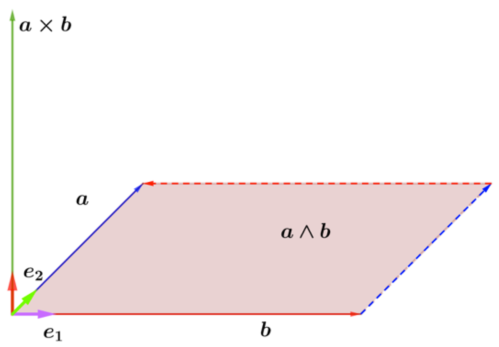
The wedge product of two vectors, and , is represented by and defines an area enclosed by the parallelogram formed by both vectors (see Figure 1). This plane has a direction and a sense, resulting in a bivector. This product complies with the anti-commutative property, i.e., .
Definition 4.
A bivector is a novel concept that introduces geometric algebra and does not exist in vectorial calculus that engineers learn in a degree course. It is the result of the external product of 2 vectors producing a plane with direction and sense, exactly as a vector would have it. Its value is equal to the area enclosed by the parallelogram formed by the vectors (see Figure 2). Like vectors, a bivector can be written as the linear combination of a base of bivectors.
Definition 5.
The geometric product is also another major contribution of the GA. It is defined primarily for vectors, although it can be extended to other objects. For example, given two vectors, and , you can define its geometric product as
that is, the geometric product is a linear combination of the internal and external product. It can be seen how the result is made up of a scalar and a bivector, resulting in the so-called multivector.
is the scalar part and is the bivector.
3. Power in Geometric Algebra
3.1. Vector Representation in Domain
Consider a periodic function in the time domain that can represent a voltage or current waveform. A function space can be established where the following norm is defined as
The norm is found to be consistent with the definition of the root mean square (RMS) value. Well, this function can be represented by a linear combination of sine and cosine functions, i.e., a series of Fourier functions. Let us call these bases , so that
so that a direct transformation to gives
where are the new basis for the geometric space . Because the new base is orthonormal, the following property is fulfilled,
Finally, we use the transformation proposed by Castro-Nuñez [25],
where represents the product of n vectors. This way, we can transform any waveform to the geometric domain .
3.2. Multivector Power
Several authors [14,17,30] have already shown that the traditional expression for apparent power (accepted by the IEEE1459 standard or Budeanu and Fryze’s proposals) is incorrect, because it does not comply with the principle of energy conservation and does not have a true physical correspondence with power flows. For example,
are expressions frequently used that violate the principle of energy conservation, so they should not be used on a regular basis, especially in nonsinusoidal scenarios as they lead to errors in the achieved results.
The addition of the concept of multivector power, geometric apparent power or net apparent power (as labeled by Castro-Núñez), opens a door for attempting to solve the aforementioned problems. This concept is totally different form the traditional definition of the nonsinusoidal apparent power S, i.e., in general, , so cannot be called apparent power. From a mathematical point of view, the expressions are simple and elegant. From a physical point of view, each term takes on a real meaning in the flow of energy between the load and the source. The geometric apparent power is defined as the geometric product between voltage and current:
which will generally result in a scalar and a bivector for the sinusoidal case.
In fact, if we consider a sinusoidal voltage applied to a linear load, we obtain a sinusoidal current,
The apparent geometric power is then
If we generalize for a nonsinusoidal voltage,
we can obtain the voltage transferred to the geometric domain .
As Castro-Nunez [37] establishes that the geometric admittance is , applying the principle of superposition yield each of the harmonic currents as . Clearly, the total current is the sum of all harmonic currents
This current can be decomposed into in-phase and quadrature components with voltage.
where
Finally, the apparent multivector geometric power can be obtained as the product between and ,
where
Based on the above definitions, the net or geometric power factor can be defined as
4. Power Factor Compensation Using Multivector Apparent Power
Once the effectiveness of the geometric power has been induced to represent the mathematical and physical energy flows, it is time to analyse how it is possible to propose compensation schemes that increase the power factor of the facilities in a microgrid.
To improve the power factor, it is necessary to eliminate any current that is not in phase with the voltage. This strategy implies that the load-compensating combination is seen as a pure resistance by the source. An example of a compensator can be seen in Figure 3, which shows the load admittance as well as the compensator admittance . The values of these admittances in the geometric domain are
If we apply the voltage given by (13), the current flowing through the compensator will be
Therefore, it is pretty obvious that to fully compensate the reactive term. In this case, the total current is reduced to as is equal to 0 after applying Kirchhoff laws.
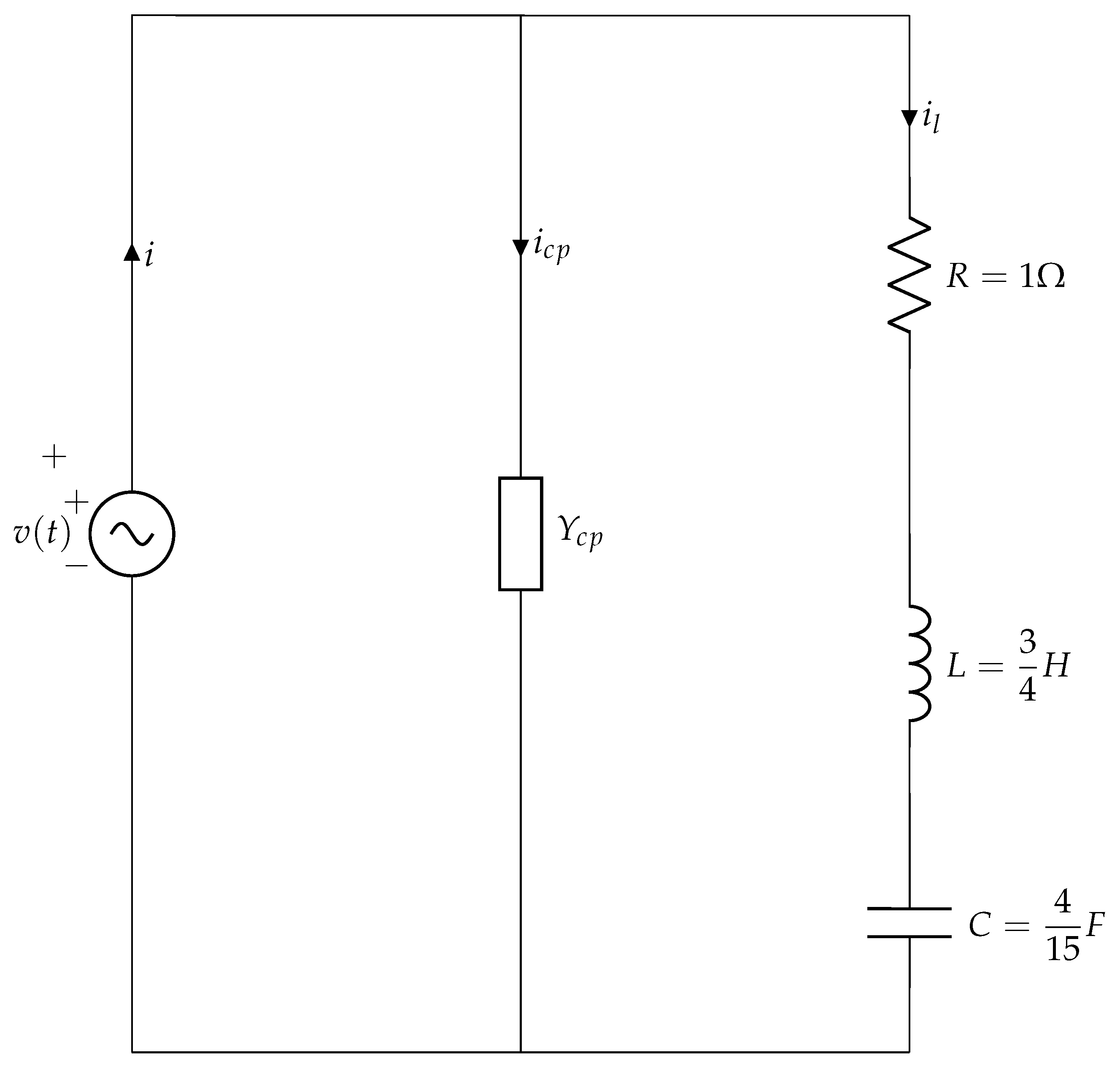
5. Application to Real Circuits
To demonstrate the robustness of geometric algebra in the resolution of nonsinusoidal electrical circuits and to verify that it is a useful and valid method, the circuit shown in Figure 4, already exposed in [33], will be solved. This theoretical circuit represents a hypothetical electrical circuit in a modern microgrid building, where the application of a nonsinusoidal voltage to a linear load results in the circulation of a nonsinusoidal current. The power involved has several components, although it will be shown how the traditional approach to power factor improvement is not very successful. Note that the proposal made in this paper also improves the one made by [33], going from a compensated power factor of 0.63 to a higher one of 0.83.
Let the nonsinusoidal voltage, , be
The geometric impedance will have two different values, one for each voltage harmonic. According to the authors of (20), the geometric impedance is defined as
where is the value of the impedance for the harmonic of order h. Applying the above expression for each harmonic present, we obtain y .
Taking into account the proposed transformation into (6), the voltage becomes
Applying the generalized Ohm law
The total current value is A. The current obtained has two clearly differentiated components, which is the component in phase with the voltage and which is the component in quadrature. As a matter of fact
which proves that both are orthogonal. The power balance can be obtained by using Equations (8) and (9):
The analysis of the multivector apparent power results in Table 1. It shows the active power P, degradation power and reactive power . This power clearly differs from that obtained by Budeanu or that obtained by the authors of [33]. A comparison of these theories is also shown in Table 2.
It is interesting to note how the multivector power presented here has a very similar correspondence with the power in the time domain. Indeed, if we take into account that the voltage and current are (see Figure 5)
we can make the product and get the time domain power
so we can rearrange as
achieving the same results as in (27).
All the power theories agree on finding the active power, P, but this is not the case for the rest of the other concepts. Both Budeanu and Castilla [33] obtain a lower reactive and apparent power, as well as a higher distortion (degraded) power. The power factor obtained by Budeanu and Castilla is also higher, giving the impression that the system is not really as degraded as it really is. As Castro-Núñez demonstrates, the other theories fail to consider the interaction between harmonics of different frequencies, and are therefore unable to fully capture the physical sense of energy flows.
This is clearly evident when trying to design a compensator that improves the power factor as much as possible. According to Castilla, this compensator is achieved by installing a capacitor in parallel with the load of a value of F, resulting in a new power factor of 0.63. Well, if we apply our theory, we can achieve a much better power factor by simply addressing the need for reactive current , according to Equations (15) and (16). See Figure 6 for the placement of the compensator in parallel with the load.
Solving the above equation yields and . Obviously, it is not possible to effectively compensate by means of a single element, as proposed in [33]. A parallel LC compensator (Other circuits may be compensated with a serial model) is therefore proposed to be installed, which will result in
Solving the previous system yields
For these compensator values, the new total current value becomes
where A which is significantly lower than the initial 154.91A. The time domain representation of compensated current is
Comparing (37) with (28) give us an idea about the current reduction thanks to the compensator. If we calculate the reactive power as in (29) and (30), the new result is
which can be arranged as
Equations (38) and (39) clearly state that all of the reactive power has been corrected through the new compensator. Furthermore, the principle of conservation of energy has been fulfilled as demonstrated in both in time and geometric domain.
Table 3 shows a summary of the compensation status. It can be seen that all the reactive current coming from the source has been suppressed, resulting in a significant reduction in geometric apparent power (from 53,666 VA to 28,844 VA). Naturally, the power factor increases considerably to 0.83, far exceeding the compensation obtained by the Budeanu or Castilla methods, in which only the placement of a capacitor in parallel with the load is considered.
6. Conclusions
This work deepens the new advances in nonsinusoidal power theory thanks to geometric algebra. Due to the large deployment of electronic loads in today’s microgrid, it is increasingly common to find a more distorted supply and with high harmonic content. This situation generates noise and harmonic pollution, degrading the power supply of the existing electrical receivers on the microgrid. In this work, a detailed study of new mathematical techniques applied to the analysis of nonsinusoidal cases is carried out, and a compensation method based on the use of geometric algebra is proposed. Thanks to this technique, it is possible to reduce the geometric reactive power component, something that other traditional methods such as Budeanu or Fryze cannot do. It is also demonstrated that the technique proposed by Castro-Nuñez is far superior to the one proposed by Castilla, as it is able to better identify the power flows due to crossed voltage and current products ( and ), which allowed identifying those components of the current not in phase with the voltage, and thus suppressing them with the appropriate compensator. The main contribution of this work is in the application of geometric algebra to the resolution of power flows in nonsinusoidal electrical systems so that their direction and sense can be correctly determined when considering compensation models. This approach opens up new perspectives in the field of nonsinusoidal systems optimisation, as well as a proper and adequate definition of indices associated with power quality.
Funding
This research has been supported by the Ministry of Science, Innovation and Universities at the University of Almeria under the programme “Proyectos de I+D de Generacion de Conocimiento” of the National Programme for the Generation of Scientific and Technological Knowledge and Strengthening of the R+D+I System, grant number PGC2018-098813- B-C33.
Acknowledgments
The author would like to thank the Spanish Government and regional authorities for their support through the grant PGC2018-098813-B-C33.
Conflicts of Interest
The author declares no conflicts of interest.
References
- Fang, X.; Misra, S.; Xue, G.; Yang, D. Smart grid—The new and improved power grid: A survey. IEEE Commun. Surv. Tutor. 2012, 14, 944–980. [Google Scholar] [CrossRef]
- Colak, I.; Sagiroglu, S.; Fulli, G.; Yesilbudak, M.; Covrig, C.F. A survey on the critical issues in smart grid technologies. Renew. Sustain. Energy Rev. 2016, 54, 396–405. [Google Scholar] [CrossRef]
- Bollen, M.H.; Das, R.; Djokic, S.; Ciufo, P.; Meyer, J.; Rönnberg, S.K.; Zavodam, F. Power quality concerns in implementing smart distribution-grid applications. IEEE Trans. Smart Grid 2017, 8, 391–399. [Google Scholar] [CrossRef]
- An, L.; Xu, Q.; Ma, F.; Chen, Y. Overview of power quality analysis and control technology for the smart grid. J. Mod. Power Syst. Clean Energy 2016, 4, 1–9. [Google Scholar] [Green Version]
- Cherian, E.; Bindu, G.; Nair, P.C. Pollution impact of residential loads on distribution system and prospects of DC distribution. Eng. Sci. Technol. Int. J. 2016, 19, 1655–1660. [Google Scholar] [CrossRef] [Green Version]
- Bouzid, A.M.; Guerrero, J.M.; Cheriti, A.; Bouhamida, M.; Sicard, P.; Benghanem, M. A survey on control of electric power distributed generation systems for microgrid applications. Renew. Sustain. Energy Rev. 2015, 44, 751–766. [Google Scholar] [CrossRef] [Green Version]
- Wang, Y.; Yong, J.; Sun, Y.; Xu, W.; Wong, D. Characteristics of harmonic distortions in residential distribution systems. IEEE Trans. Power Deliv. 2017, 32, 1495–1504. [Google Scholar] [CrossRef]
- Schwanz, D.; Bollen, M.; Larsson, A.; Kocewiak, ŁH. Harmonic mitigation in wind power plants: Active filter solutions. In Proceedings of the IEEE 2016 17th International Conference on the Harmonics and Quality of Power (ICHQP), Belo Horizonte, Brazil, 16–19 October 2016; pp. 220–225. [Google Scholar]
- Steinmetz, C.P. Theory and Calculation of Alternating Current Phenomena; McGraw-Hill Book Company, Incorporated: New York, NY, USA, 1916; Volume 4. [Google Scholar]
- Orts-Grau, S.; Munoz-Galeano, N.; Alfonso-Gil, J.C.; Gimeno-Sales, F.J.; Segui-Chilet, S. Discussion on useless active and reactive powers contained in the IEEE standard 1459. IEEE Trans. Power Deliv. 2011, 26, 640–649. [Google Scholar] [CrossRef]
- Emanuel, A.E. Powers in nonsinusoidal situations-a review of definitions and physical meaning. IEEE Trans. Power Deliv. 1990, 5, 1377–1389. [Google Scholar] [CrossRef]
- Page, C.H. Reactive power in nonsinusoidal situations. IEEE Trans. Instrum. Meas. 1980, 29, 420–423. [Google Scholar] [CrossRef]
- Czarnecki, L.S.; Pearce, S.E. Compensation objectives and Currents’ Physical Components–based generation of reference signals for shunt switching compensator control. IET Power Electron. 2009, 2, 33–41. [Google Scholar] [CrossRef]
- Willems, J.L. Budeanu’s reactive power and related concepts revisited. IEEE Trans. Instrum. Meas. 2011, 60, 1182–1186. [Google Scholar] [CrossRef]
- De Léon, F.; Cohen, J. AC power theory from Poynting theorem: Accurate identification of instantaneous power components in nonlinear-switched circuits. IEEE Trans. Power Deliv. 2010, 25, 2104–2112. [Google Scholar] [CrossRef]
- Jeon, S.J. Considerations on a reactive power concept in a multiline system. IEEE Trans. Power Deliv. 2006, 21, 551–559. [Google Scholar] [CrossRef]
- Czarnecki, L.S. On some misinterpretations of the instantaneous reactive power pq theory. IEEE Trans. Power Electron. 2004, 19, 828–836. [Google Scholar] [CrossRef]
- Budeanu, C. Puissances Reactives et Fictives; Number 2; Impr. Cultura Nationala: Paris, France, 1927. [Google Scholar]
- Staudt, V. Fryze-Buchholz-Depenbrock: A time-domain power theory. In Proceedings of the IEEE 2008 International School on Nonsinusoidal Currents and Compensation ( ISNCC 2008), Lagow, Poland, 10–13 June 2008; pp. 1–12. [Google Scholar]
- Czarnecki, L.S. What is wrong with the Budeanu concept of reactive and distortion power and why it should be abandoned. IEEE Trans. Instrum. Meas. 1987, 1001, 834–837. [Google Scholar] [CrossRef]
- Czarnecki, L. Budeanu and fryze: Two frameworks for interpreting power properties of circuits with nonsinusoidal voltages and currentsBudeanu und Fryze-Zwei Ansätze zur Interpretation der Leistungen in Stromkreisen mit nichtsinusförmigen Spannungen und Strömen. Electr. Eng. 1997, 80, 359–367. [Google Scholar] [CrossRef]
- Czarnecki, L.S. Currents’ physical components (CPC) concept: A fundamental of power theory. In Proceedings of the IEEE 2008 International School on Nonsinusoidal Currents and Compensation (ISNCC 2008), Lagow, Poland, 10–13 June 2008; pp. 1–11. [Google Scholar]
- Castro-Núñez, M. The Use of Geometric Algebra in the Analysis of Non-sinusoidal Networks and the Construction of a Unified Power Theory for Single Phase Systems-A Paradigm Shift. Ph.D. Thesis, University of Calgary, Calgary, AB, USA, 2013. [Google Scholar]
- Castro-Nuñez, M.; Castro-Puche, R. The IEEE Standard 1459, the CPC power theory, and geometric algebra in circuits with nonsinusoidal sources and linear loads. IEEE Trans. Circuits Syst. I Regul. Pap. 2012, 59, 2980–2990. [Google Scholar] [CrossRef]
- Castro-Nuñez, M.; Castro-Puche, R. Advantages of geometric algebra over complex numbers in the analysis of networks with nonsinusoidal sources and linear loads. IEEE Trans. Circuits Syst. I Regul. Pap. 2012, 59, 2056–2064. [Google Scholar] [CrossRef]
- Menti, A.; Zacharias, T.; Milias-Argitis, J. Geometric algebra: A powerful tool for representing power under nonsinusoidal conditions. IEEE Trans. Circuits Syst. I Regul. Pap. 2007, 54, 601–609. [Google Scholar] [CrossRef]
- Castilla, M.; Bravo, J.C.; Ordoñez, M. Geometric algebra: A multivectorial proof of Tellegen’s theorem in multiterminal networks. IET Circuits Dev. Syst. 2008, 2, 383–390. [Google Scholar] [CrossRef]
- Castilla, M.; Bravo, J.C.; Ordonez, M.; Montaño, J.C. Clifford theory: A geometrical interpretation of multivectorial apparent power. IEEE Trans. Circuits Syst. I Regul. Pap. 2008, 55, 3358–3367. [Google Scholar] [CrossRef]
- Hestenes, D. Point groups and space groups in geometric algebra. In Applications of Geometric Algebra in Computer Science and Engineering; Springer: Berlin, Germany, 2002; pp. 3–34. [Google Scholar]
- Castro-Núñez, M.; Londoño-Monsalve, D.; Castro-Puche, R. M, the conservative power quantity based on the flow of energy. J. Eng. 2016, 2016, 269–276. [Google Scholar] [CrossRef]
- Czarnecki, L.S. Minimisation of distortion power of nonsinusoidal sources applied to linear loads. IEE Proc. C (Gener. Transm. Distrib.) 1981, 128, 208–210. [Google Scholar] [CrossRef]
- Czarnecki, L.S. Considerations on the Reactive Power in Nonsinusoidal Situations. IEEE Trans. Instrum. Meas. 1985, IM-34, 399–404. [Google Scholar] [CrossRef]
- Castilla, M.V.; Bravo, J.C.; Martin, F.I. Multivectorial strategy to interpret a resistive behaviour of loads in smart buildings. In Proceedings of the 2018 IEEE 12th International Conference on Compatibility, Power Electronics and Power Engineering (CPE-POWERENG 2018), Doha, Qatar, 10–12 April 2018; pp. 1–5. [Google Scholar]
- Hestenes, D.; Sobczyk, G. Clifford Algebra to Geometric Calculus: A Unified Language for Mathematics and Physics; Springer Science & Business Media: Berlin, Germany, 2012; Volume 5. [Google Scholar]
- Hestenes, D. New Foundations for Classical Mechanics; Springer Science & Business Media: Berlin, Germany, 2012; Volume 15. [Google Scholar]
- Chappell, J.M.; Drake, S.P.; Seidel, C.L.; Gunn, L.J.; Iqbal, A.; Allison, A.; Abbott, D. Geometric algebra for electrical and electronic engineers. Proc. IEEE 2014, 102, 1340–1363. [Google Scholar] [CrossRef]
- Castro-Núñez, M.; Castro-Puche, R.; Nowicki, E. The use of geometric algebra in circuit analysis and its impact on the definition of power. In Proceedings of the IEEE 2010 International School on Nonsinusoidal Currents and Compensation (ISNCC), Lagow, Poland, 15–18 June 2010; pp. 89–95. [Google Scholar]
Figure 1.
Wedge product of 2 vectors and .

Figure 2.
Representation of a bivector .

Figure 3.
Circuit compensation proposal.

Figure 4.
Building equivalent circuit.

Figure 5.
Nonsinusoidal voltage and current waveforms.

Figure 6.
Building equivalent circuit with compensator.


Table 1.
Power multivector decomposition.
| Description | Value |
|---|---|
| 24,000 W | |
| 16,000 VA | |
| 45,254 VA |
Table 2.
Power before compensation.
| Description | Budeanu | Castilla | Castro-Núñez |
|---|---|---|---|
| Active Power | 24,000 | 24,000 | 24,000 |
| Reactive Power | 8000 | 8000 | 45,254 |
| Distortion/Degraded Power | 35,780 | 35,780 | 16,000 |
| Apparent/Geometric Power | 43,820 | 43,820 | 53,666 |
| Power factor | 0.55 | 0.55 | 0.44 |
Table 3.
Power after LC compensation.
| Description | Budeanu | Castilla | Castro-Núñez |
|---|---|---|---|
| Active Power | 24,000 | 24,000 | 24,000 |
| Reactive Power | 11,000 | 11,000 | 0 |
| Distortion/Degraded Power | 27,530 | 27,530 | 16,000 |
| Apparent/Geometric Power | 38,200 | 38,200 | 28,844 |
| Power factor | 0.63 | 0.63 | 0.83 |
© 2019 by the author. Licensee MDPI, Basel, Switzerland. This article is an open access article distributed under the terms and conditions of the Creative Commons Attribution (CC BY) license (http://creativecommons.org/licenses/by/4.0/).
Share and Cite
MDPI and ACS Style
Montoya, F.G. Geometric Algebra in Nonsinusoidal Power Systems: A Case of Study for Passive Compensation. Symmetry 2019, 11, 1287. https://doi.org/10.3390/sym11101287
AMA Style
Montoya FG. Geometric Algebra in Nonsinusoidal Power Systems: A Case of Study for Passive Compensation. Symmetry. 2019; 11(10):1287. https://doi.org/10.3390/sym11101287
Chicago/Turabian StyleMontoya, Francisco G. 2019. "Geometric Algebra in Nonsinusoidal Power Systems: A Case of Study for Passive Compensation" Symmetry 11, no. 10: 1287. https://doi.org/10.3390/sym11101287
Note that from the first issue of 2016, this journal uses article numbers instead of page numbers. See further details here.