Symmetric-in-Plane Compression of Polyamide Pantographic Fabrics—Modelling, Experiments and Numerical Exploration


1
International Research Center for the Mathematics and Mechanics of Complex Systems, University of L’Aquila, 67100 L’Aquila, Italy
2
45stages sp. z o.o. - Nowy Swiat 39/1, 00-029 Warsaw, Poland
3
Institute of Mechanics and Printing, Warsaw University of Technology, 02-524 Warsaw, Poland
*
Author to whom correspondence should be addressed.
Symmetry 2020, 12(5), 693; https://doi.org/10.3390/sym12050693
Submission received: 30 December 2019
/
Revised: 11 March 2020
/
Accepted: 16 March 2020
/
Published: 1 May 2020
(This article belongs to the Special Issue Recent Advances in the Study of Symmetry and Continuum Mechanics)
Abstract
:Symmetric in-plane compression of a pantographic lattice structure is modelled and simulated, and the results are compared to previously available experimental data. Said experimental results had shown a peculiar behaviour: depending on the fiber density, the deformed shape could present either one or two swellings under compression. The present article is a preliminary modelling attempt aiming at capturing that behaviour numerically.
1. Introduction
1.1. Generalised Continua and Their Use to Model Pantographic Structures
Generalised continua have been studied for the past decades [1,2,3,4,5], and have been used more recently to model the mechanical behaviour of pantographic structures [6,7]. They are indeed a typical example of structures that may be modelled as discrete [8,9,10,11,12] or semi discrete [13] systems, which may also be homogenised into second gradient continua [14,15,16]. Those modelling processes may involve extensional and bending elements [17,18,19,20], generalised shells theory [21,22,23], surface elasticity [24,25], or second gradient continua theory [26,27,28]. More specifically, second gradient models raised some mathematical challenges [29,30], and their study needed the interaction between analytical parameters identification [31,32] and numerical simulation [33,34,35,36,37], while taking into account the fibers constituting the pantographic lattice [38,39,40,41,42,43].
1.2. Model-Driven Design and Synthesis of Pantographic Structures
Pantographic structures are an example of so-called metamaterials [44,45], i.e., they are the result of a model-driven design: given a set of equations, pantographic structures were synthesised in order to follow the very behaviour that is defined by those starting equations. Here, the considered theoretical behaviour is that of an elastic material whose deformation energy may depend only on strain gradient under certain conditions. In other words, pantographic structures are an answer to the synthesis problem of a material that may be modeled as a second gradient continuum.
As a consequence of the peculiar origin of pantographic structures, their study needs a synergy between: first, the starting theoretical model; second, the numerical modelling and simulation of that theoretical model; and last, the manufacturing of, and experimental tests on, real specimen. Regarding that last aspect, studies have been made to understand the influence of certain 3D-printing processes and constitutive materials [46,47,48,49] on the mechanical behaviour of the resulting specimena [50]. Other studies focused on how the design of different mechanical elements inside the structure may affect their global behaviour [51]. Those studies considered different scales, from micrometers [52] to millimetres [53], as well as how the different behaviours at different scales may be linked [54,55]. Studying those various scales involved new methodologies which have been developed for the (micro)mechanics of granular media [56,57,58]. The experimental studies yielded interesting results, such as the ability of pantographic structures to deform elastically for high deformations and how their qualitative behaviour does not depend on their constitutive material [59]. New phenomena have also been observed, like a reversed Poynting effect [60] which led to less known features of the model. There were also advances in the damage mechanics of pantographic structures: their damaging was proven to be highly dependent on their geometry and material properties [61], and their overall resistance to damage was studied by enhanced elastic models [8]. Future prospects concerning the experimental study of pantographic structures involve the promising use of digital image correlation (DIC) techniques as a way to improve the synergy needed for model-driven design [62]. Regarding recent numerical results, pantographic structures have been modelled using finite elements at macroscopic [12] and mesoscopic scales, by using differently built meshes [45,63].
1.3. Out-of-Plane and In-Plane Compression of Pantographic Fabrics
In this article, we want to continue these lines of investigations, by attempting the modelling of in-plane compression of thick polyamide pantographic fabrics. Previous litterature in pantographic has extensively dealt with their tensile behaviour [9,38,39]. Further experimental evidence concerned their compresssion behaviour, originating locally in shear tests [8,64]. In such cases, only two layers of fibers were employed and the thickness of the pantographic fabrics was not predominant with respect to other total specimen dimensions. In those cases, cross-section of fibers constituting pantographic fabrics had a very small out-of-plane bending rigidity with respect to the in-plane one. This was due to their low (out-of-plane) thickness. Therefore, pure in-plane compression could not be observed.
By increasing the out-of-plane thickness of the constituting fibers, we avoid out-of-plane buckling, and are able to perform for the first time a purely in-plane compression test. Those experimental results are described in the present work, and a preliminary numerical investigation is reported.
1.4. Plan of the Present Work
The plan of the paper is the following. In Section 2, the main features of the used strain gradient continuum model are recalled, as well as its numerical modelling using finite elements. More specifically, a linear model for small perturbations is presented and adpated to higher deformations, by introducing several parameters whose values are to be determined by a numerical-experimental comparison.
In Section 3, the available experimental specimena are presented along the data that are considered to fit the theoretical model.
In Section 4, the different steps of the model fitting are described. Using force-displacement graphs and boundary shapes to quantitatively and qualitatively compare the numerical and experimental results, the model parameters are identified and the final model is discussed.
Section 5 summarises the work and gathers the relevant results, before ending with future propspects on how to further the presented work.
2. Mathematical and Numerical Modelling of Pantographic Structures
In this section the general theoretical framework that will be used to model the studied pantographic structures is presented. The elastic behaviour of the studied pantographic sheet is modeled as a strain gradient continuum. This model does not describe each fiber separately, but considers the global homogenised behaviour instead. We first recall the key features of that model, before presenting its numerical modelling by the finite elements method.
2.1. Geometrically Non Linear Second Gradient Elasticity Model
The reference configuration of the studied system is represented by an open domain , its boundary (edges) and the boudary of its boundary (wedges). More specifically, is a rectangle, due to the considered geometry (see Section 3). We consider an orthonormal basis of . Any generic element of will be noted (only tensor notations are used, but they may also represent the associated vector, linear map or matrix in the basis ).
2.1.1. Kinematics
For all , we define the placement as:
and the respective current configurations . We also define the displacement . The placement is assumed to be of class and locally affine. Its gradient will be noted , so that the Green–Lagrange strain tensor may be expressed as . For the sake of notation simplicity and unless specified otherwise, we will now fix a time parameter and will no longer write it explicitly.
2.1.2. Potential Energy
We define a potential energy functional taking the displacement field as its argument. It accounts for both internal and external effects; formally:
External Work
is the external work. Introducing the surface body force , the linear contact force and double force , and the vertex forces , the external work may be rewritten as:
Strain Energy—Linear Elasticity
is the elastic deformation energy. It depends on the strain tensor G and its gradient . We define its density U as follows:
The studied pantographic structure is made of two families of beams. It is thus orthotropic, the two privileged directions being those of each family. Moreover, the peculiar geometry of the model makes it invariant for a rotation, as well as for a mirror reflection. That is to say, it is invariant for the symmetry group.
Under orthotropy and symmetry hypotheses, [65] gives the following expression for the linearised strain gradient deformation energy (here, denotes square matrices, row matrices and column matrices):
where the row matrix gathers the values of the linearised strain tensor :
and the matrices are defined as:
For the linearised case, Placidi et al. [32] derived the values of the and matrices using analytical solutions. They obtained the form:
where and (“lin” for “linear case”) depend on the geometry and stiffness of the fibers, as well as the density of the fabric (see [32] for the complete derivation):
being the constitutive material’s Young modulus, the cross-section area, the second moment of area of the cross-section, and the distance between two adjacent fibers of the same family.
Strain Energy—Higher Deformations
Although the previous results were derived for the linear case, the same form for the energy will be assumed in the present work. Therefore, the deformation energy to be considered is expressed as:
where, this time, the strain terms in and are not linearised:
and the coefficients are substituted with parameters whose values should be determined numerically, in order to fit the model with experimental results. Furthermore, the pivots are not considered perfect, and their torsional deformation energy is taken into account by an additional parameter :
Thus, the aim is to build an elastic model for large displacements, starting from a small perturbations model and identifying the defined parameters by fitting them from experimental data.
2.1.3. Variational Approach
The problem to solve is derived using a variational approach. The previously defined potential energy is assumed to be minimised for the equilibrium displacement field . Thus, the weak form is obtained as the stationarity condition of the potential energy.
The boundary conditions are:
- prescribed null displacement at the lower edge:
- no applied load on either side:
- prescribed displacement on the upper edge:
2.2. Finite Elements Numerical Model
Function Space
Since the energy to be minimised involves the second gradient of displacement, the function space should be in . Thus, the chosen element type is cubic Hermite functions, in order to have approximations. Moreover, the boundary conditions are taken into account as constraints rather than in the function space.
Modelling with Software
The software Comsol is used for the numerical modelling. A rectangular geometry is defined and meshed (see Section 4). The compresion test is then modelled as a parametric study on the imposed displacement . The equilibrium is computed for each value of from the results of the its previous value.
3. Experimental Specimen
3.1. Studied Class of Pantographic Structure
The class of pantographic structures under study is a lattice made of two families of fibers. Every fiber is parallel to the other fibers of the same family, but orthogonal to those of the other family. Each family is planar, and the two considered families are parallel but not in the same plane, so that there is no actual intersection between the two families. However, each family is connected to the other one by what may be called pivots, located wherever the distance between two fibers from different families is minimal. Furthermore, the density of fibers is constant, so that the distance between two adjacent fibers of the same family is constant.
3.2. Modelled Specimen: Production and Characterisation
Some key elements are summarised, regarding the experimental specimen to be modelled. The machines and procedures involved are mostly similar to those presented in [51], to which the reader may refer for more details.
The specimen were printed using Powder Bed Fusion technology, more specifically Selective Laser Sintering. A Formiga P100 printer by EOS was used from Warsaw University of Technology, with EOS PA2200 polyamide powder. Every specimen was printed in horizontal configuration, i.e., the pantographic sheets were printed parallel to the support. Each layer was 0.1 mm thick.
The fibers constituting the two printed structures had the following nominal dimensions:
- Width of beam: 0.9 mm
- Height of beam: 4 mm
- Width of pivot: 0.9 mm
- Height of pivot: 1 mm
and the uncertainty for the actual specimen was 0.05 mm for the width and height of beams, and 0.1 mm for the height and width of pivots.
The values that are numerically implemented will be presented in the next section (Section 4).
3.3. Experimental Procedure
The compression tests were carried out using an MTS Bionix machine in Warsaw University of Technology. One side of the specimen was fixed while the other one’s displacement was imposed with a speed of 4 mm/min. The length of the specimen being 21 cm, the speed is around 2% of the length per minute. The measurement sensitivities are 1 N for the force and 0.1 mm for the displacement.
Before the compression tests themselves, each specimen underwent 200 cycles alternating between elongation and compression, in order to eliminate the powder remaining after printing. Those cycles were made with a 1 Hz frequency and 20 mm amplitude.
3.4. Outputs of the Experiments
The experimental results were used to fit the theoretical model, each specimen having a different purpose.
Specimen 1 was used for quantitative comparison. During its compression, the reaction force was measured. Thus, the outputs of the first experiment were the evolution of the reaction and the imposed displacement. Those results were then exploited to fit the numerical parameters presented in Section 2.
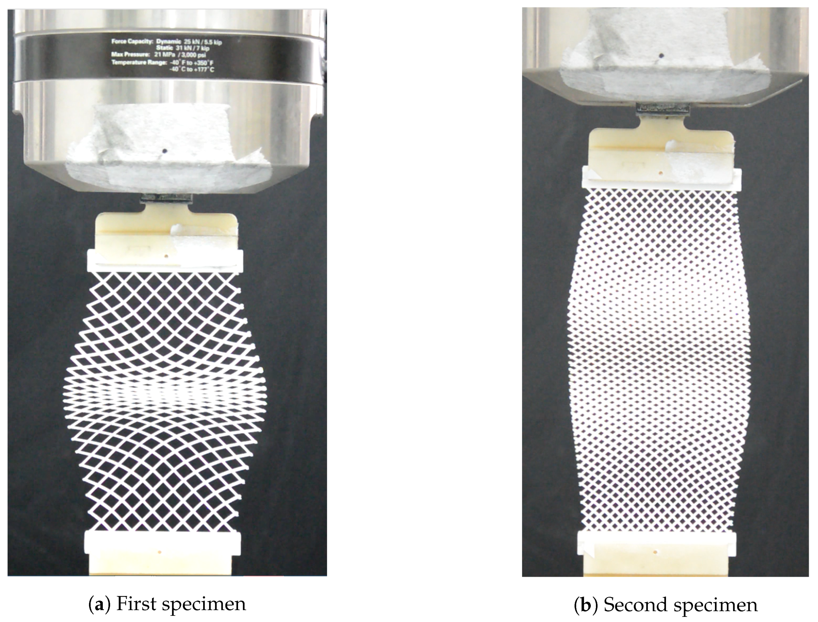
Specimen 2 was used for qualitative comparison. More specifically, it showed a peculiar shape under compression (see Figure 2b), presenting two swellings, while Specimen 1 only had one swelling. Thus, the objective of the second experiment was to verify whether the fitted theoretical model was able to catch the shape of the specimen.
Measurement Uncertainty
Force measurement sensitivity is N. Assuming a uniform probability distribution, the type B uncertainty is evaluated as the standard deviation N.
Thus, for a measured value , the force lies in , and has 58% probability to be in .
4. Model Fitting and Numerical Validation
The model presented in Section 2 is now implemented using the software Comsol. We recall that the aim of this preliminary work is to verify whether the presented model can actually be adapated to high deformations. Thus, the following study is rather qualitative, as a more precise quantitative study will be carried out in future works.
4.1. Numerical Parameters
4.1.1. Fixed Parameters
The numerical compression tests involved two lattices made of the same fibers having the same geometry and made from the same constitutive material (polyamide). The common dimensions and material properties are gathered in Table 1. Both resulting pantographic sheets had length and width.
The only difference between those two structures was the distance between adjacent fibers of the same family. Thus, only the density of fibers characterized each specimen.
4.1.2. Parameters to Be Fitted
The theoretical model involves three parameters , and in need of identification in order to fit the model to the experimental results. This identification follows several steps, and uses the compression results of the first experimental specimen:
- begin with the linear case values: ; and
- fit to experimental results (force-displacement graph)
Furthermore, once the identification is done, a qualitative comparison is made with the second specimen’s compression, in order to verify if the right boundary shape can be rendered by the model.
4.2. First Experiment—Single Swelling
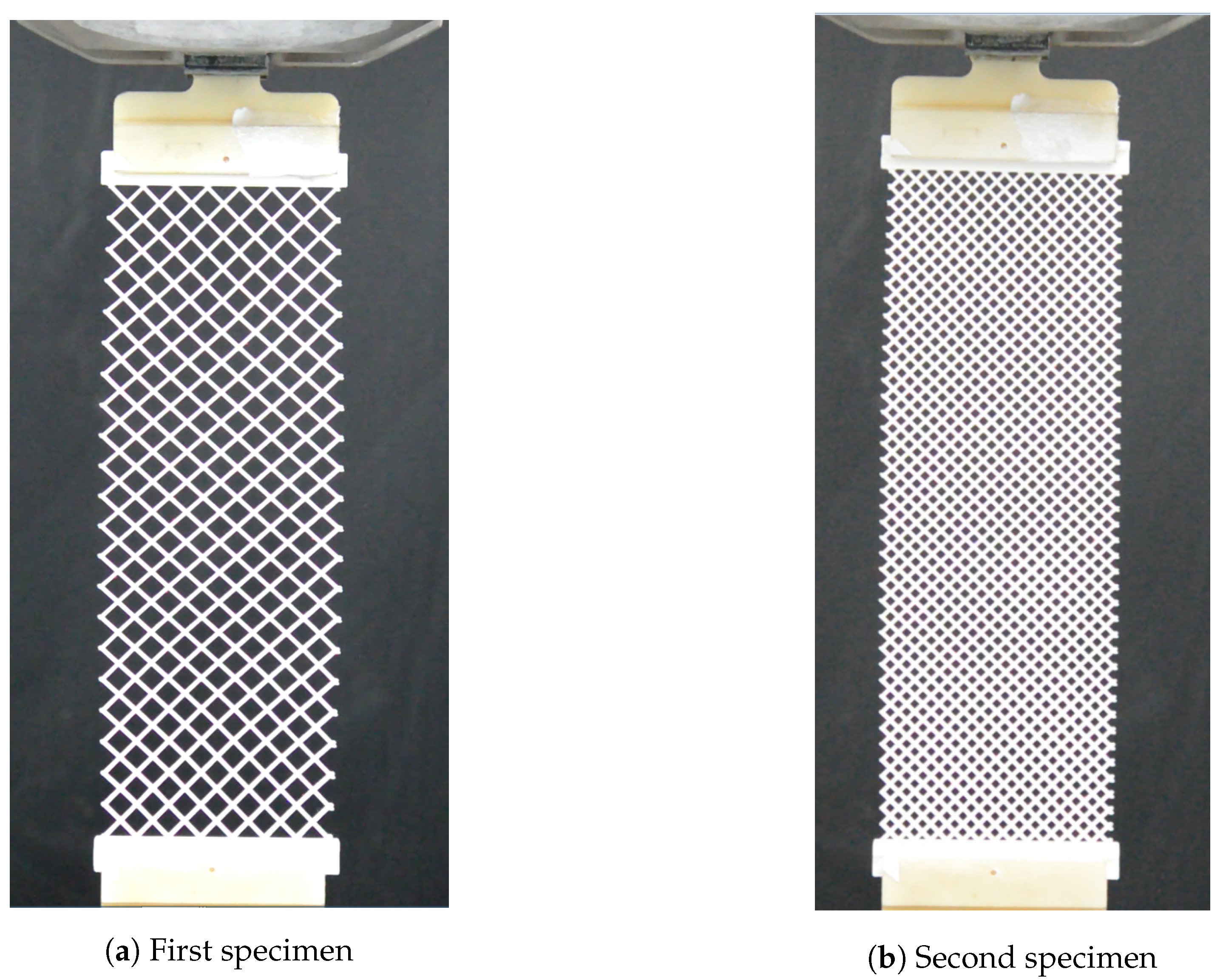
We first perform the parameter identification, using the compression of Specimen 1 (Figure 1a).
4.2.1. Without Torsional Energy
We begin with and only, leaving a null torsional energy parameter .
Parameter Values
Force-Displacement Graph Comparison
The graph resulting from the simulation is plotted in Figure 3, as well as the experimental measurements. Measured force error-type is represented by the grey area around the experimental graph.
It is clear that the considered parameter values are not enough to predict the experimental results. The next step is to verify whether changing the value of the torsional parameter may suffice to fit the model.
One may also notice an apparent softening phenomenon in the numerical model, around an imposed displacement of mm. This softening is also to be investigated in the next step.
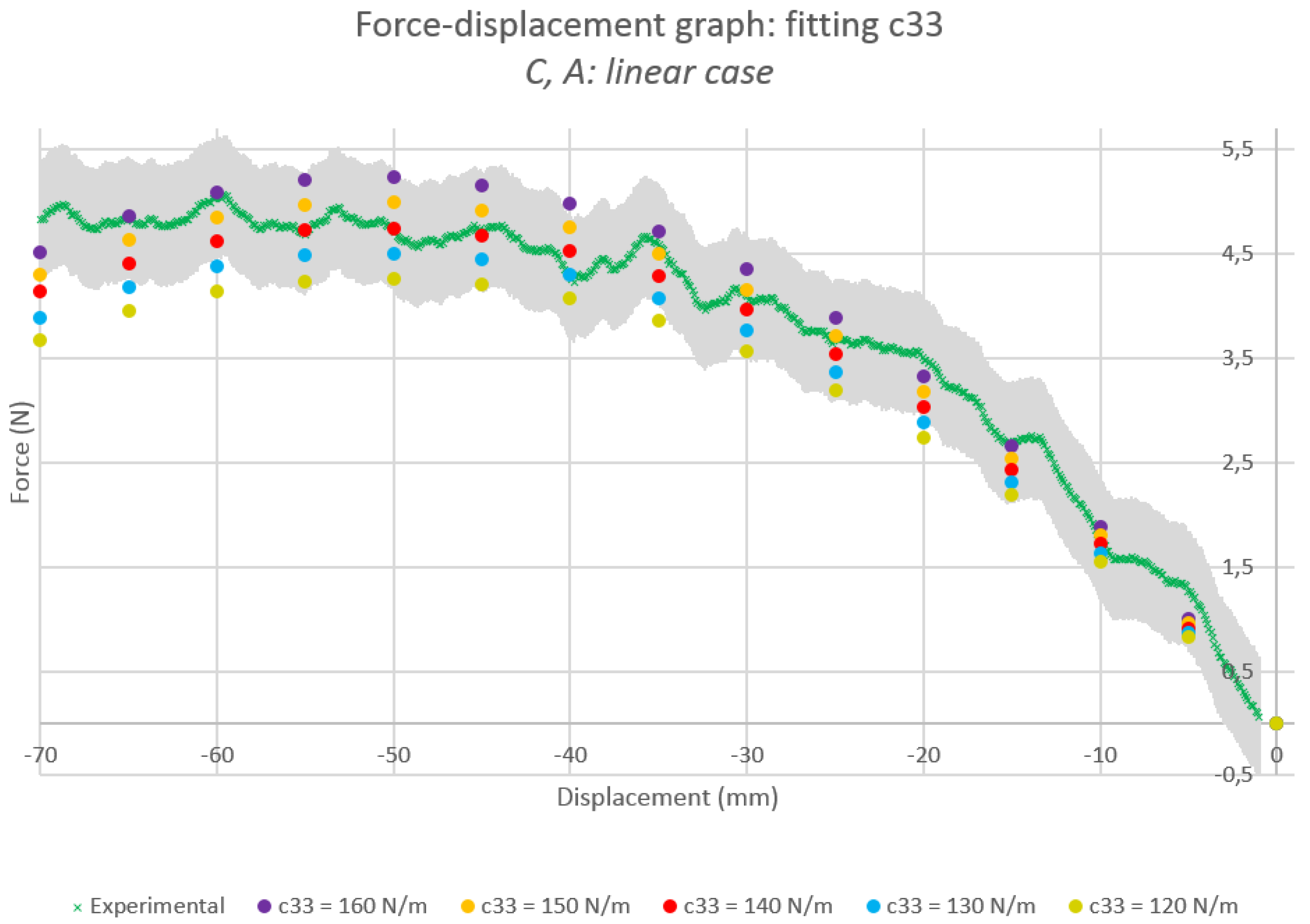
4.2.2. Fitting the Torsional Parameter
Several values for between 0 and 200 N/m were tested (Figure 4). The value for which the numerical force-displacement graph seemed to be the closest to experimental data was
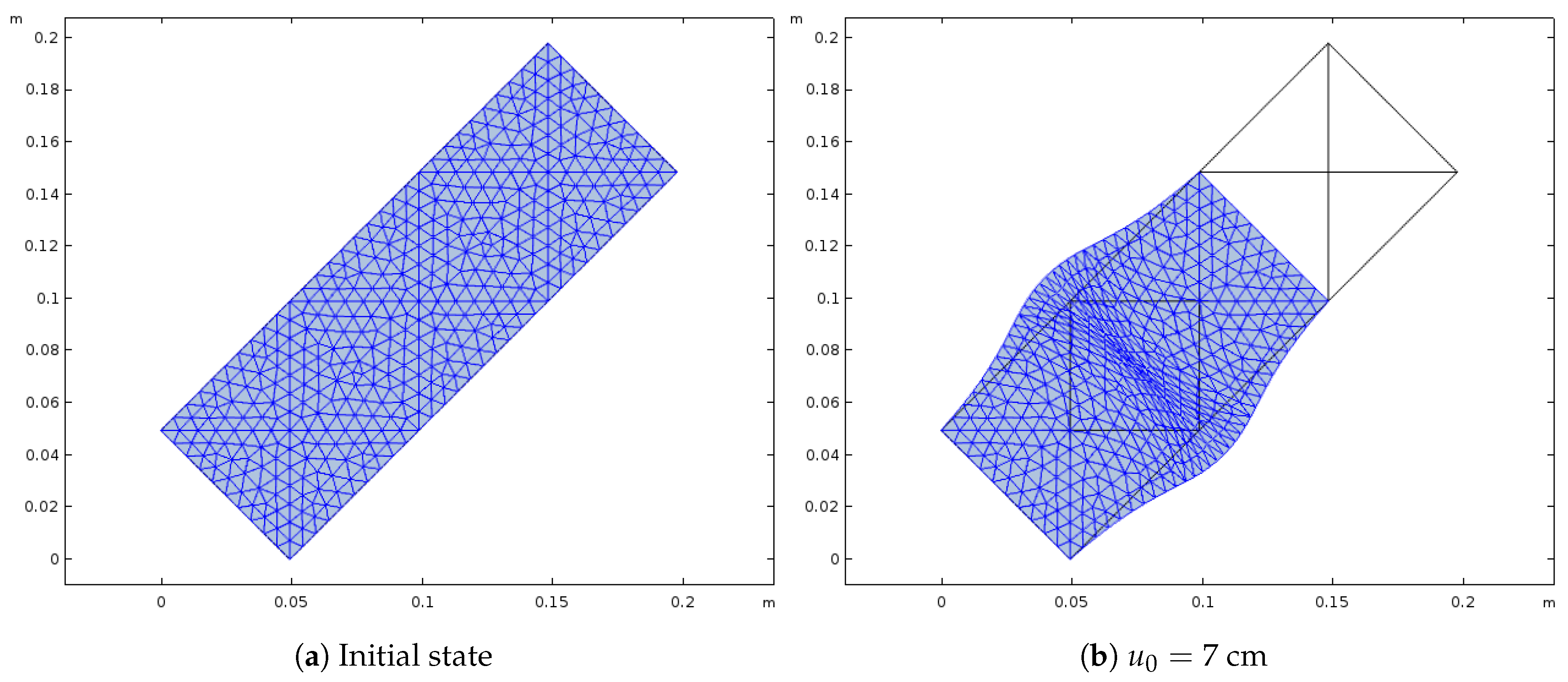
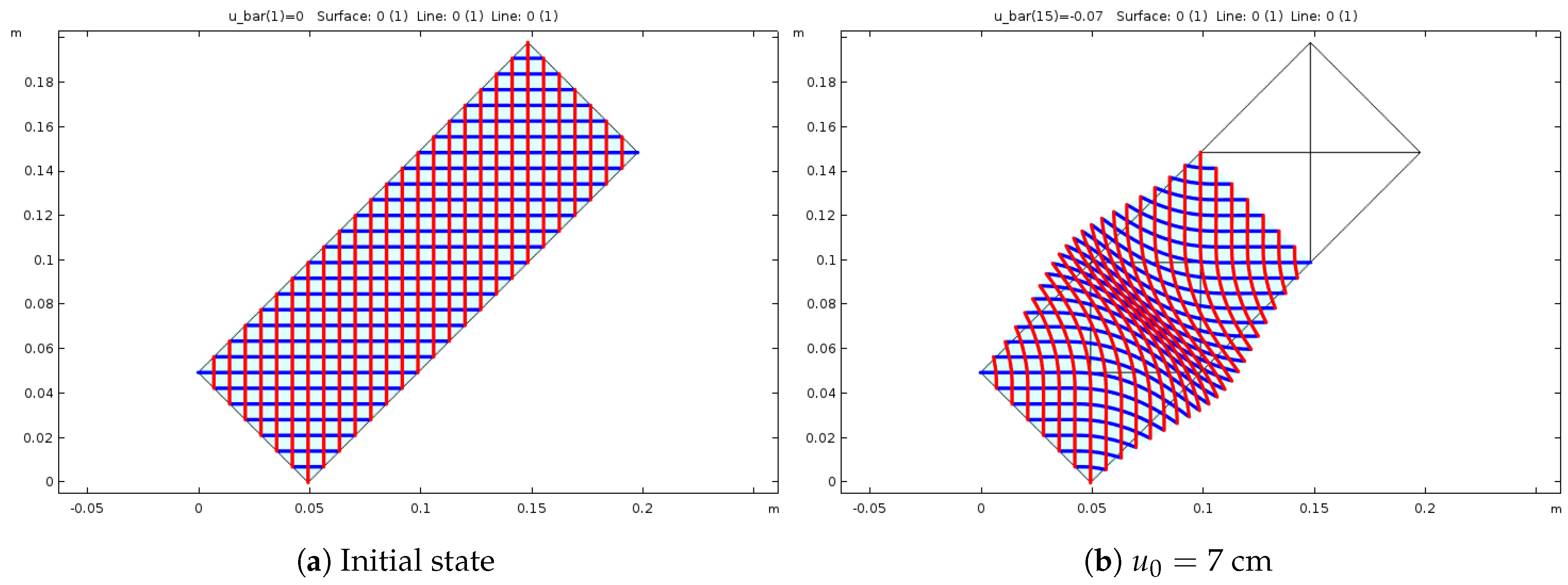
with the corresponding graph in Figure 5. The geometry and mesh of the numerical model is depicted in Figure 6, in the initial state and for an imposed displacement of cm. A graphical representation of the fibers was also defined in the numerical model, and can be seen in Figure 7.
The resulting model seems to agree with the experimental results until an imposed displacement of 5 cm, that is to say a 24% deformation. At that point, there is once again an apparent softening, beyond which the theoretical model is clearly non valid.
The actual shape of the experimental specimen at the apparent softening was investigated to see whether a contact between fibers may have caused a difference between experimental and numerical behaviours. However, no such contact was seen on the experimental specimen, for any value of prescribed displacement. The numerical model was also verified for the same displacement (Figure 8), and no such contact was seen either. Thus, the origin of this apparent softening must still be investigated.
Now that the model is fitted, the next step is to verify whether the presence of two swellings instead of a single one may be predicted by the model.
4.3. Second Experiment—Two Swellings
The specimen to be modelled is depicted in Figure 1b, and its numerical counterpart in Figure 9 (with a representation of the fibers). The mesh remains the same as previously.
Parameter Values
Since the distance between fibers is the only quantity differing Specimen 1 and Specimen 2, and are recalculated with the right value of (see Table 2), while remains the same.
Qualitative Comparison
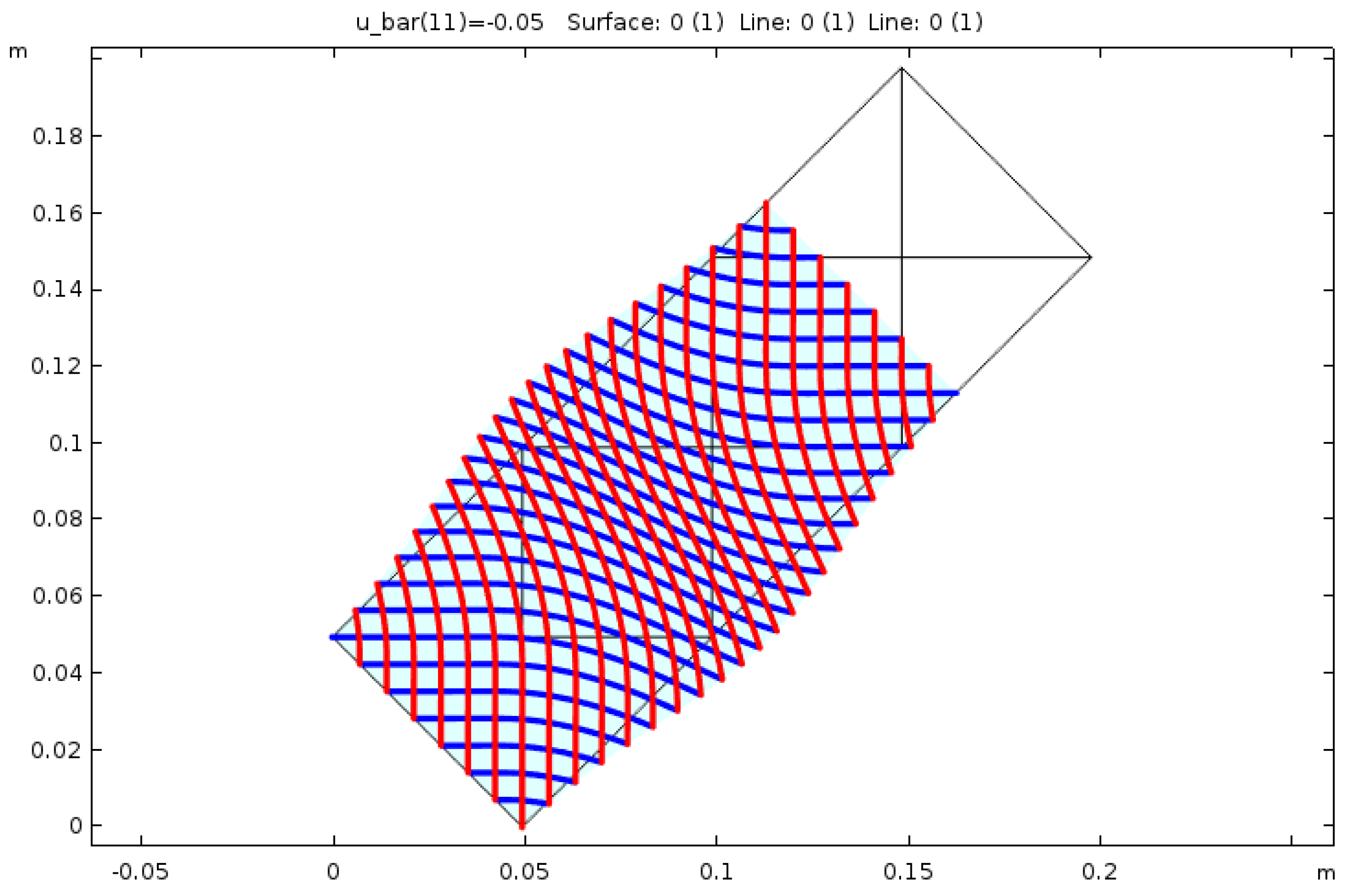
The numerical resulting shape is depicted in Figure 10, for an imposed displacement cm. Only one swelling is visible, while the experimental results showed two of them (Figure 2b). Thus, for the considered parameter identification, the model does not predict the right boundary shape.
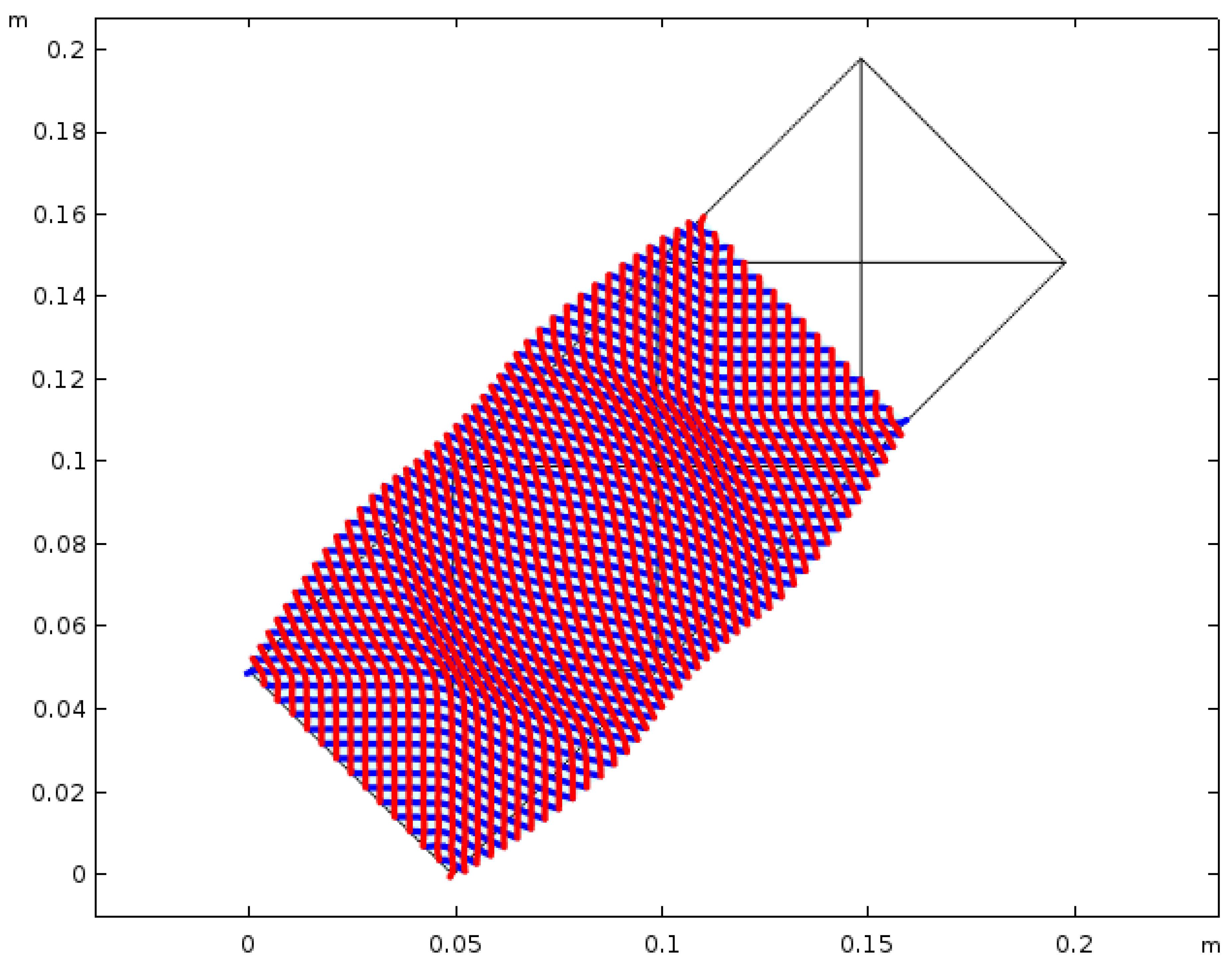
However, the double swelling can be observed for the same model, when other arbitrary values are given to the parameters (Figure 11).
Consequently, while the model is able to render both single and double swellings, the parameter identification still needs to be improved. This discrepancy may be due to the hypotheses on which the parameter values were derived in [32]. More specifically, each fiber is assumed to behave as an Euler beam; this assumption should be investigated to determine whether it may be too restritive to model the compression of the studied lattice structure.
5. Conclusion and Possible Future Work
5.1. Work Done
The elastic response of a pantographic sheet to a compressive load was modelled. This behaviour was then numerically simulated, and the parameters of the model were fitted to experimental data.
A continuous strain gradient elasticity model was used in the presented work, assuming a quasi-static regime and a bidimensional geometry presenting a dihedral symmetry. It was derived through a variational approach, by assuming that the equilibrium point minimises the total potential energy. This model has already been used in previous works, more specifically from [32], in a small displacement and deformation framework. It was here adapted to higher deformation cases. Indeed, the deformation energy was supposed to keep the same form for high deformation as for small perturbations. It was then parametrised by coefficients to be fitted numerically to experimental compression results.
Said fitting first involved finite elements modelling: using cubic Hermite elements to keep functions, the stationary condition of the potential energy was discretised using the software Comsol. The considered boundary conditions were imposed displacements, which were applied as constraints. This numerical model was then simulated, the outputs being the evolution of the reaction force against the imposed displacement, as well as the geometric shape of the boundary.
Regarding the experimental data, compression tests of two specimen were considered. Both were 3D-printed polyamide pantographic sheets, differing only by the density of fibers. Available results were, quantitatively, the evolution of the measured reaction force and imposed displacement, and qualitatively the evolution of the general shape of each specimen.
The experimental and numerical results were then compared in order to identify the parameters of the theoretical model.
5.2. Results
First, quantitative comparisons between the numerical and experimental force-displacement graphs led to the identification of the model’s parameters. The two parameters c and a which were derived in [32] kept the values they had for small perturbations. The last parameter was adjusted to fit the numerical and experimental reaction force. The resulting model agrees with the experimental data up to an imposed displacement of 5 cm, i.e., a 24% deformation. An apparent softening phenomenon is then observed in the theoretical model, but does not correspond to any experimental data. In particular, there was no contact between fibers during the compression tests at that displacement. This discrepancy may be due to the hypotheses of the theoretical model. More specifically, the analytically-derived parameters a and c were calculated by considering each fiber to behave as an Euler beam, which may be too restrictive an assumption to properly model the lattice.
However, since this is a preliminary work, we recall that the interest of the previous results lies not in the values themselves, but rather in the possibility of applying the presented method to adapt a linear model to high deformation cases.
Second, a qualitative comparison of the boundary shape revealed a varying number of swellings depending on the considered specimen or parameter values. Indeed, the denser experimental specimen developped two swellings during its compression, while the other only had one. However, the corresponding models showed only one swelling. Nonetheless, the theoretical model does capture the double-swelling phenomenon for other, arbitrary parameter values. It means that, while the parameter identification should be investigated in order to model properly the experimental specimen, the model itself is still able to predict the double-swelling phenomenon.
5.3. Possible Future Work
This preliminary work should be followed by more precise studies with respect to both the experimental and numerical values.
Regarding the model, it may be interesting first to look for an analytical explanation of the varying number of swellings, as well as why a softening appears. Second, and as said above, the parameters’ identification was made on an Euler beam hypothesis. Studying more specifically the influence of this assumption may reveal more clearly its limits, and enable an exploration of other modelling possibilities.
Concerning the experimental aspect, the accuracy of the data may be improved by other measurement methods, for example by using digital image correlation techniques [62]. Moreover, a better quantification of measurement uncertainty may improve the precision of the experimental data, thus yielding more relevant results for the numerical-experimental comparison.
Author Contributions
Conceptualization, E.B.; Formal analysis, E.B.; Investigation, M.G.; Resources, M.G.; Software, C.A.T.; Supervision, E.B.; Visualization, C.A.T.; Writing—original draft, C.A.T.; Writing—review & editing, E.B., C.A.T. All authors have read and agreed to the published version of the manuscript.
Funding
This research received no external funding.
Acknowledgments
The Authors thank Lekszycki for his kind hospitality at Warsaw University of Technology, where this work was carried out, and for the stimulating discussions.
Conflicts of Interest
The authors declare no conflict of interest.
References
- Maugin, G.A. Generalized continuum mechanics: What do we mean by that? In Mechanics of Generalized Continua; Springer: New York, NY, USA, 2010; pp. 3–13. [Google Scholar]
- Green, A.E. Micro-materials and multipolar continuum mechanics. Int. J. Eng. Sci. 1965, 3, 533–537. [Google Scholar] [CrossRef]
- Mindlin, R.D. Second gradient of strain and surface-tension in linear elasticity. Int. J. Solids Struct. 1965, 1, 417–438. [Google Scholar] [CrossRef]
- Toupin, R.A. Theories of Elasticity with Couple-Stress; Springer: Berlin, Germany, 1964. [Google Scholar]
- Dell’Isola, F.; Corte, A.D.; Giorgio, I. Higher-gradient continua: The legacy of Piola, Mindlin, Sedov and Toupin and some future research perspectives. Math. Mech. Solids 2017, 22, 852–872. [Google Scholar] [CrossRef]
- dell’Isola, F.; Giorgio, I.; Pawlikowski, M.; Rizzi, N.L. Large deformations of planar extensible beams and pantographic lattices: Heuristic homogenization, experimental and numerical examples of equilibrium. Proc. R. Soc. A Math. Phys. Eng. Sci. 2016, 472, 20150790. [Google Scholar] [CrossRef] [Green Version]
- Dell’Isola, F.; Lekszycki, T.; Pawlikowski, M.; Grygoruk, R.; Greco, L. Designing a light fabric metamaterial being highly macroscopically tough under directional extension: First experimental evidence. Z. Für Angew. Math. Und Phys. 2015, 66, 3473–3498. [Google Scholar] [CrossRef]
- Turco, E.; Dell’Isola, F.; Rizzi, N.L.; Grygoruk, R.; Müller, W.H.; Liebold, C. Fiber rupture in sheared planar pantographic sheets: Numerical and experimental evidence. Mech. Res. Commun. 2016, 76, 86–90. [Google Scholar] [CrossRef] [Green Version]
- Turco, E.; Golaszewski, M.; Cazzani, A.; Rizzi, N.L. Large deformations induced in planar pantographic sheets by loads applied on fibers: Experimental validation of a discrete Lagrangian model. Mech. Res. Commun. 2016, 76, 51–56. [Google Scholar] [CrossRef]
- Turco, E.; Rizzi, N.L. Pantographic structures presenting statistically distributed defects: Numerical investigations of the effects on deformation fields. Mech. Res. Commun. 2016, 77, 65–69. [Google Scholar] [CrossRef]
- Turco, E.; Giorgio, I.; Misra, A.; Dell’Isola, F. King post truss as a motif for internal structure of (meta) material with controlled elastic properties. R. Soc. Open Sci. 2017, 4, 171153. [Google Scholar] [CrossRef] [Green Version]
- Turco, E.; Misra, A.; Pawlikowski, M.; Dell’Isola, F.; Hild, F. Enhanced Piola–Hencky discrete models for pantographic sheets with pivots without deformation energy: Numerics and experiments. Int. J. Solids Struct. 2018, 147, 94–109. [Google Scholar] [CrossRef] [Green Version]
- Andreaus, U.; Spagnuolo, M.; Lekszycki, T.; Eugster, S.R. A Ritz approach for the static analysis of planar pantographic structures modeled with nonlinear Euler–Bernoulli beams. Contin. Mech. Thermodyn. 2018, 30, 1103–1123. [Google Scholar] [CrossRef]
- Carcaterra, A.; dell’Isola, F.; Esposito, R.; Pulvirenti, M. Macroscopic description of microscopically strongly inhomogenous systems: A mathematical basis for the synthesis of higher gradients metamaterials. Arch. Ration. Mech. Anal. 2015, 218, 1239–1262. [Google Scholar] [CrossRef]
- Alibert, J.J.; Seppecher, P.; Dell’Isola, F. Truss modular beams with deformation energy depending on higher displacement gradients. Math. Mech. Solids 2003, 8, 51–73. [Google Scholar] [CrossRef]
- Abdoul-Anziz, H.; Seppecher, P. Strain gradient and generalized continua obtained by homogenizing frame lattices. Math. Mech. Complex Syst. 2018, 6, 213–250. [Google Scholar] [CrossRef] [Green Version]
- Steigmann, D.J.; Faulkner, M.G. Variational theory for spatial rods. J. Elast. 1993, 33, 1–26. [Google Scholar] [CrossRef] [Green Version]
- Spagnuolo, M.; Andreaus, U. A targeted review on large deformations of planar elastic beams: Extensibility, distributed loads, buckling and post-buckling. Math. Mech. Solids 2019, 24, 258–280. [Google Scholar] [CrossRef]
- Cazzani, A.; Malagù, M.; Turco, E.; Stochino, F. Constitutive models for strongly curved beams in the frame of isogeometric analysis. Math. Mech. Solids 2016, 21, 182–209. [Google Scholar] [CrossRef]
- Cazzani, A.; Malagù, M.; Turco, E. Isogeometric analysis: A powerful numerical tool for the elastic analysis of historical masonry arches. Contin. Mech. Thermodyn. 2016, 28, 139–156. [Google Scholar] [CrossRef]
- Eremeyev, V.A.; Lebedev, L.P.; Altenbach, H. Foundations of Micropolar Mechanics; Springer Science & Business Media: Berlin, Germany, 2012. [Google Scholar]
- Altenbach, H.; Eremeyev, V.A. On the linear theory of micropolar plates. ZAMM-J. Appl. Math. Mech. Für Angew. Math. Und Mech. 2009, 89, 242–256. [Google Scholar] [CrossRef] [Green Version]
- Altenbach, H.; Bîrsan, M.; Eremeyev, V.A. Cosserat-type rods. In Generalized Continua from the Theory to Engineering Applications; Springer: Vienna, Austria, 2013; pp. 179–248. [Google Scholar]
- Eremeyev, V.A. Strongly anisotropic surface elasticity and antiplane surface waves. Philos. Trans. R. Soc. A 2020, 378, 20190100. [Google Scholar] [CrossRef] [Green Version]
- Eremeyev, V.A.; Sharma, B.L. Anti-plane surface waves in media with surface structure: Discrete vs. Contin. Model. Int. J. Eng. Sci. 2019, 143, 33–38. [Google Scholar] [CrossRef] [Green Version]
- Dell’Isola, F.; Placidi, L. Variational principles are a powerful tool also for formulating field theories. In Variational Models and Methods in Solid and Fluid Mechanics; Springer: Vienna, Austria, 2011; pp. 1–15. [Google Scholar]
- Dell’Isola, F.; Seppecher, P.; Corte, A.D. The postulations á la D’Alembert and á la Cauchy for higher gradient continuum theories are equivalent: A review of existing results. Proc. R. Soc. A Math. Phys. Eng. Sci. 2015, 471, 20150415. [Google Scholar] [CrossRef] [PubMed] [Green Version]
- Dell’Isola, F.; Madeo, A.; Seppecher, P. Cauchy tetrahedron argument applied to higher contact interactions. Arch. Ration. Mech. Anal. 2016, 219, 1305–1341. [Google Scholar] [CrossRef] [Green Version]
- Eremeyev, V.A.; Dell’Isola, F.; Boutin, C.; Steigmann, D. Linear pantographic sheets: Existence and uniqueness of weak solutions. J. Elast. 2018, 132, 175–196. [Google Scholar] [CrossRef] [Green Version]
- Placidi, L.; El Dhaba, A.R. Semi-inverse method à la Saint-Venant for two-dimensional linear isotropic homogeneous second-gradient elasticity. Math. Mech. Solids 2017, 22, 919–937. [Google Scholar] [CrossRef]
- Placidi, L.; Andreaus, U.; Della Corte, A.; Lekszycki, T. Gedanken experiments for the determination of two-dimensional linear second gradient elasticity coefficients. Z. Für Angew. Math. Und Phys. 2015, 66, 3699–3725. [Google Scholar] [CrossRef]
- Placidi, L.; Andreaus, U.; Giorgio, I. Identification of two-dimensional pantographic structure via a linear D4 orthotropic second gradient elastic model. J. Eng. Math. 2017, 103, 1–21. [Google Scholar] [CrossRef]
- Khakalo, S.; Niiranen, J. Isogeometric analysis of higher-order gradient elasticity by user elements of a commercial finite element software. Comput.-Aided Des. 2017, 82, 154–169. [Google Scholar] [CrossRef]
- Niiranen, J.; Khakalo, S.; Balobanov, V.; Niemi, A.H. Variational formulation and isogeometric analysis for fourth-order boundary value problems of gradient-elastic bar and plane strain/stress problems. Comput. Methods Appl. Mech. Eng. 2016, 308, 182–211. [Google Scholar] [CrossRef]
- Balobanov, V.; Kiendl, J.; Khakalo, S.; Niiranen, J. Kirchhoff–Love shells within strain gradient elasticity: Weak and strong formulations and an H3-conforming isogeometric implementation. Comput. Methods Appl. Mech. Eng. 2019, 344, 837–857. [Google Scholar] [CrossRef]
- Abali, B.E.; Müller, W.H.; dell’Isola, F. Theory and computation of higher gradient elasticity theories based on action principles. Arch. Appl. Mech. 2017, 87, 1495–1510. [Google Scholar] [CrossRef] [Green Version]
- Abali, B.E.; Müller, W.H.; Eremeyev, V.A. Strain gradient elasticity with geometric nonlinearities and its computational evaluation. Mech. Adv. Mater. Mod. Process. 2015, 1, 1–11. [Google Scholar] [CrossRef] [Green Version]
- Dell’Isola, F.; d’Agostino, M.V.; Madeo, A.; Boisse, P.; Steigmann, D. Minimization of shear energy in two dimensional continua with two orthogonal families of inextensible fibers: The case of standard bias extension test. J. Elast. 2016, 122, 131–155. [Google Scholar] [CrossRef]
- Dell’Isola, F.; Della Corte, A.; Greco, L.; Luongo, A. Plane bias extension test for a continuum with two inextensible families of fibers: A variational treatment with Lagrange multipliers and a perturbation solution. Int. J. Solids Struct. 2016, 81, 1–12. [Google Scholar] [CrossRef]
- Placidi, L.; Greco, L.; Bucci, S.; Turco, E.; Rizzi, N.L. A second gradient formulation for a 2D fabric sheet with inextensible fibres. Z. Für Angew. Math. Und Phys. 2016, 67, 114. [Google Scholar] [CrossRef]
- Eremeyev, V.A. Two-and three-dimensional elastic networks with rigid junctions: Modeling within the theory of micropolar shells and solids. Acta Mech. 2019, 230, 3875–3887. [Google Scholar] [CrossRef] [Green Version]
- Eremeyev, V.A. A nonlinear model of a mesh shell. Mech. Solids 2018, 53, 464–469. [Google Scholar] [CrossRef]
- Sharma, B.L.; Eremeyev, V.A. Wave transmission across surface interfaces in lattice structures. Int. J. Eng. Sci. 2019, 145, 103173. [Google Scholar] [CrossRef]
- Barchiesi, E.; Spagnuolo, M.; Placidi, L. Mechanical metamaterials: A state of the art. Math. Mech. Solids 2019, 24, 212–234. [Google Scholar] [CrossRef]
- Dell’Isola, F.; Seppecher, P.; Alibert, J.J.; Lekszycki, T.; Grygoruk, R.; Pawlikowski, M.; Steigmann, D.; Giorgio, I.; Andreaus, U.; Turco, E.; et al. Pantographic metamaterials: An example of mathematically driven design and of its technological challenges. Contin. Mech. Thermodyn. 2019, 31, 851–884. [Google Scholar] [CrossRef] [Green Version]
- Spagnuolo, M.; Peyre, P.; Dupuy, C. Phenomenological aspects of quasi-perfect pivots in metallic pantographic structures. Mech. Res. Commun. 2019, 101, 103415. [Google Scholar] [CrossRef]
- Dell’Erba, R. Rheo-mechanical and rheo-optical characterisation of ultra high molecular mass poly (methylmethacrylate) in solution. Polymer 2001, 42, 2655–2663. [Google Scholar] [CrossRef] [Green Version]
- Avella, M.; Dell’Erba, R.; Martuscelli, E. Fiber reinforced polypropylene: Influence of iPP molecular weight on morphology, crystallization, and thermal and mechanical properties. Polym. Compos. 1996, 17, 288–299. [Google Scholar] [CrossRef]
- Avella, M.; Casale, L.; Dell’Erba, R.; Martuscelli, E. Broom fibers as reinforcement for thermoplastic matrices. In Macromolecular Symposia; Hüthig & Wepf Verlag: Napoli, Italy, 1998. [Google Scholar]
- dell’Isola, F.; Seppecher, P.; Spagnuolo, M.; Barchiesi, E.; Hild, F.; Lekszycki, T.; Giorgio, I.; Placidi, L.; Andreaus, U.; Cuomo, M.; et al. Advances in pantographic structures: Design, manufacturing, models, experiments and image analyses. Contin. Mech. Thermodyn. 2019, 31, 1231–1282. [Google Scholar] [CrossRef] [Green Version]
- Golaszewski, M.; Grygoruk, R.; Giorgio, I.; Laudato, M.; Di Cosmo, F. Metamaterials with relative displacements in their microstructure: Technological challenges in 3D printing, experiments and numerical predictions. Contin. Mech. Thermodyn. 2019, 31, 1015–1034. [Google Scholar] [CrossRef]
- Dell’Isola, F.; Turco, E.; Misra, A.; Vangelatos, Z.; Grigoropoulos, C.; Melissinaki, V.; Farsari, M. Force–displacement relationship in micro-metric pantographs: Experiments and numerical simulations. Comptes Rendus Mécanique 2019, 347, 397–405. [Google Scholar] [CrossRef]
- Nejadsadeghi, N.; De Angelo, M.; Drobnicki, R.; Lekszycki, T.; dell’Isola, F.; Misra, A. Parametric experimentation on pantographic unit cells reveals local extremum configuration. Exp. Mech. 2019, 59, 927–939. [Google Scholar] [CrossRef] [Green Version]
- Yang, H.; Müller, W.H. Computation and experimental comparison of the deformation behavior of pantographic structures with different micro-geometry under shear and torsion. J. Theor. Appl. Mech. 2019, 57, 421–434. [Google Scholar] [CrossRef]
- Yang, H.; Ganzosch, G.; Giorgio, I.; Abali, B.E. Material characterization and computations of a polymeric metamaterial with a pantographic substructure. Z. Für Angew. Math. Und Phys. 2018, 69, 105. [Google Scholar] [CrossRef]
- Misra, A.; Singh, V. Micromechanical model for viscoelastic materials undergoing damage. Contin. Mech. Thermodyn. 2013, 25, 343–358. [Google Scholar] [CrossRef]
- Misra, A.; Poorsolhjouy, P. Granular micromechanics model for damage and plasticity of cementitious materials based upon thermomechanics. Math. Mech. Solids 2015. [Google Scholar] [CrossRef]
- Misra, A.; Singh, V. Thermomechanics-based nonlinear rate-dependent coupled damage-plasticity granular micromechanics model. Contin. Mech. Thermodyn. 2015, 27, 787–817. [Google Scholar] [CrossRef]
- De Angelo, M.; Spagnuolo, M.; D’annibale, F.; Pfaff, A.; Hoschke, K.; Misra, A.; Dupuy, C.; Peyre, P.; Dirrenberger, J.; Pawlikowski, M. The macroscopic behavior of pantographic sheets depends mainly on their microstructure: Experimental evidence and qualitative analysis of damage in metallic specimen. Contin. Mech. Thermodyn. 2019, 31, 1181–1203. [Google Scholar] [CrossRef]
- Misra, A.; Lekszycki, T.; Giorgio, I.; Ganzosch, G.; Müller, W.H.; Dell’Isola, F. Pantographic metamaterials show atypical Poynting effect reversal. Mech. Res. Commun. 2018, 89, 6–10. [Google Scholar] [CrossRef] [Green Version]
- Spagnuolo, M.; Barcz, K.; Pfaff, A.; Dell’Isola, F.; Franciosi, P. Qualitative pivot damage analysis in aluminum printed pantographic sheets: Numerics and experiments. Mech. Res. Commun. 2017, 83, 47–52. [Google Scholar] [CrossRef] [Green Version]
- Yildizdag, M.E.; Tran, C.A.; Barchiesi, E.; Spagnuolo, M.; dell’Isola, F.; Hild, F. A Multi-disciplinary Approach for Mechanical Metamaterial Synthesis: A Hierarchical Modular Multiscale Cellular Structure Paradigm. In State of the Art and Future Trends in Material Modeling; Springer: Cham, Switzerland, 2019; pp. 485–505. [Google Scholar]
- Dell’Isola, F.; Steigmann, D.J. (Eds.) Discrete and Continuum Models for Complex Metamaterials; Cambridge University Press: Cambridge, UK, 2020. [Google Scholar]
- Barchiesi, E.; Ganzosch, G.; Liebold, C.; Placidi, L.; Grygoruk, R.; Müller, W.H. Out-of-plane buckling of pantographic fabrics in displacement-controlled shear tests: Experimental results and model validation. Contin. Mech. Thermodyn. 2019, 31, 33–45. [Google Scholar] [CrossRef]
- Auffray, N.; Dirrenberger, J.; Rosi, G. A complete description of bi-dimensional anisotropic strain-gradient elasticity. Int. J. Solids Struct. 2015, 69, 195–206. [Google Scholar] [CrossRef]
Figure 1.
First specimen: initial state.

Figure 2.
First specimen: during compression.

Figure 3.
Numerical-experimental comparison—Specimen 1, not fitted (, , N/m). The grey area represents the error-type.
Figure 3.
Numerical-experimental comparison—Specimen 1, not fitted (, , N/m). The grey area represents the error-type.
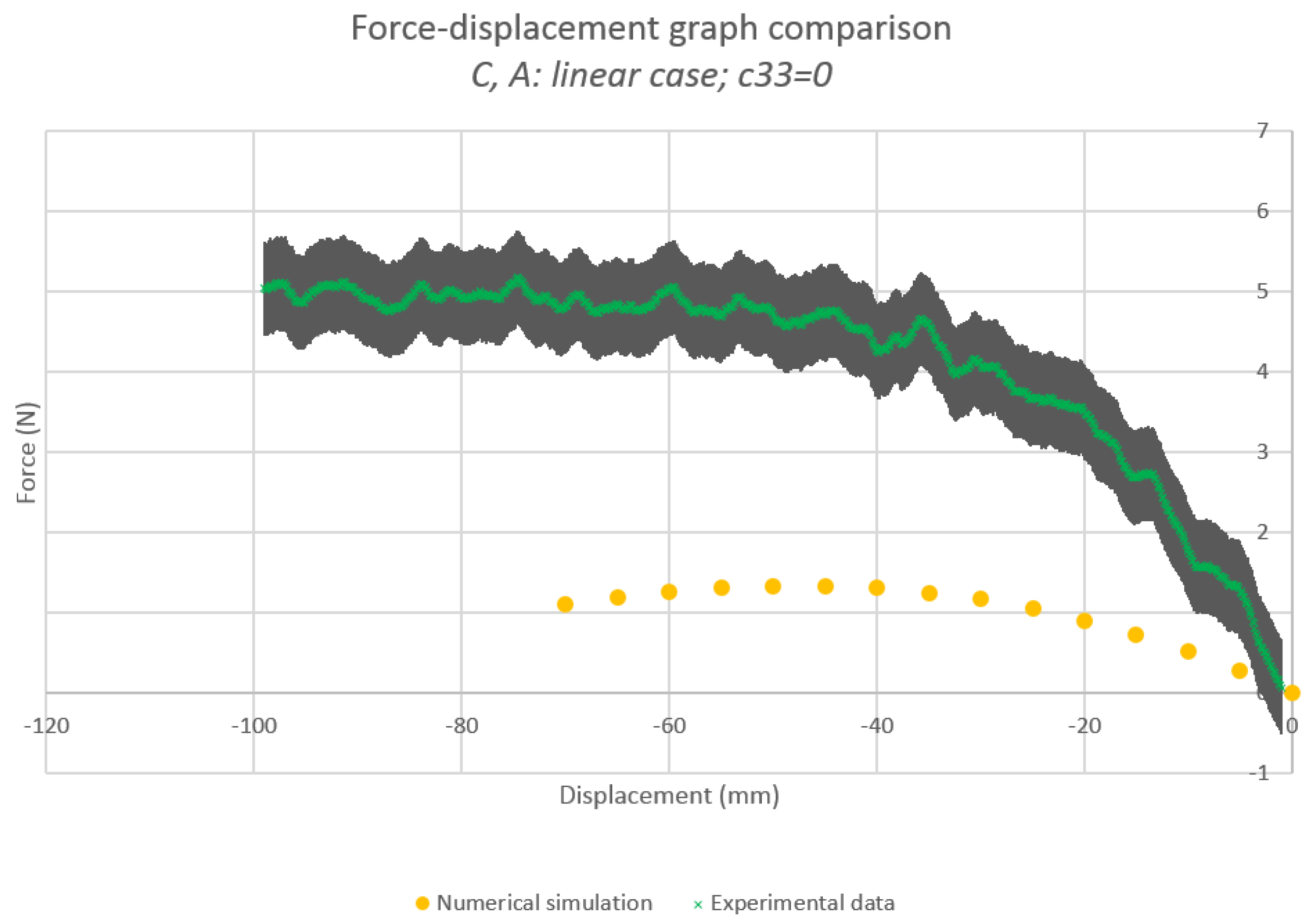
Figure 4.
Fitting ( J, N/m).

Figure 5.
Numerical-experimental comparison—Specimen 1, fitted (, , N/m). The grey area represents the error-type.
Figure 5.
Numerical-experimental comparison—Specimen 1, fitted (, , N/m). The grey area represents the error-type.
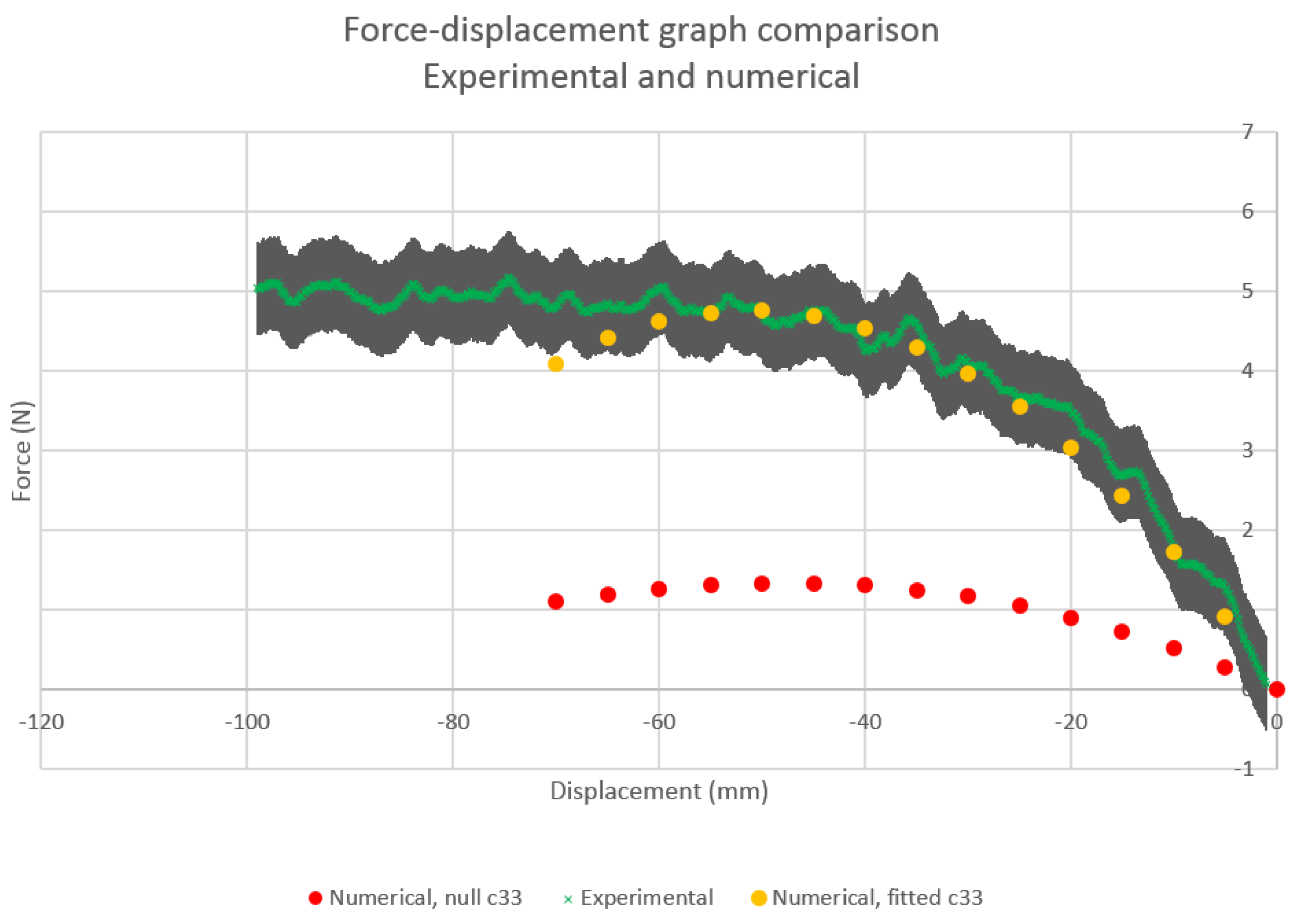
Figure 6.
Mesh during compression (820 domain elements, 164 boundary elements)—Specimen 1, fitted.

Figure 7.
Fibers during compression—Specimen 1, fitted.

Figure 8.
cm—Specimen 1, fitted.

Figure 9.
Fibers, initial state—Specimen 2, fitted.
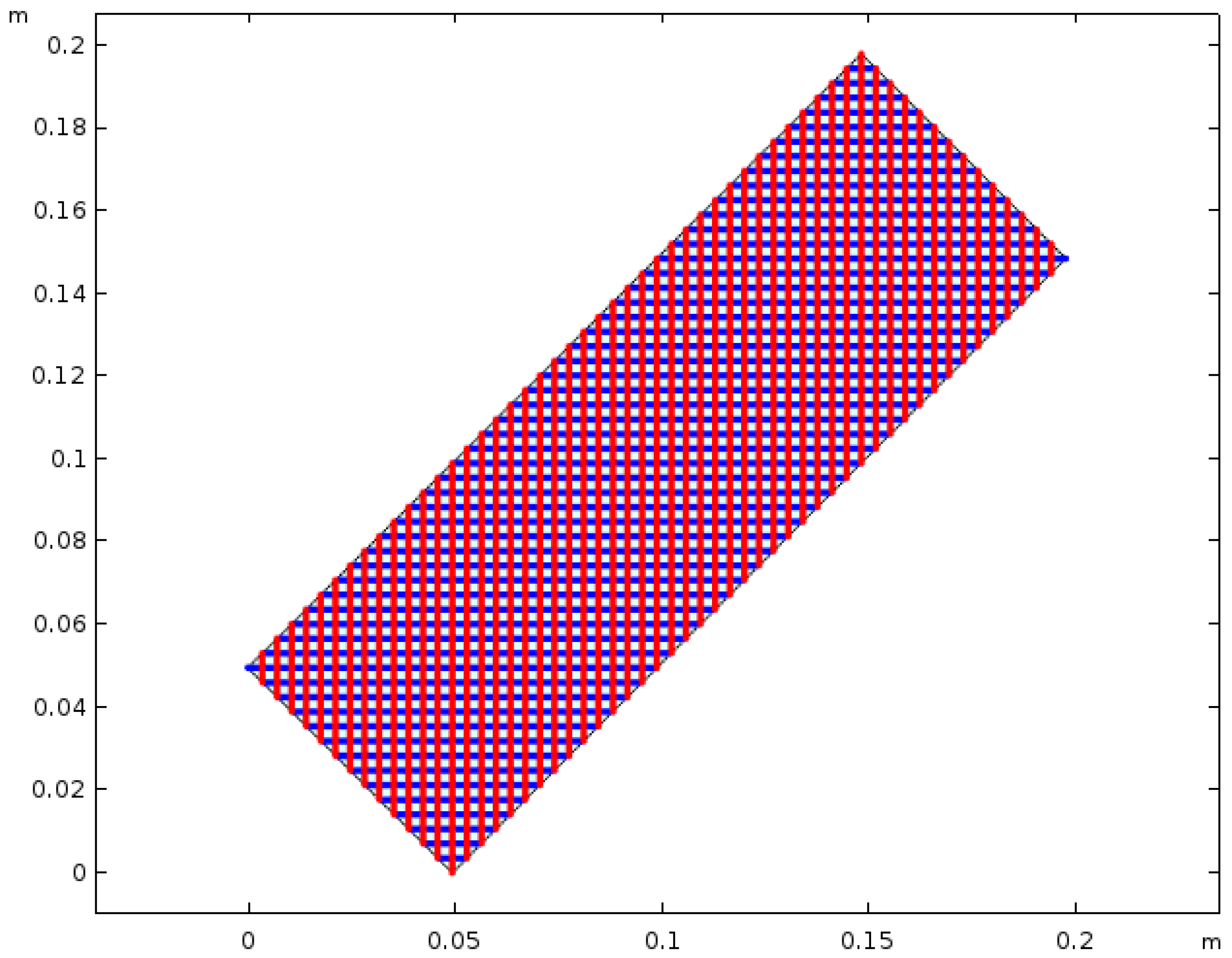
Figure 10.
Fibers, cm—Specimen 2, fitted.
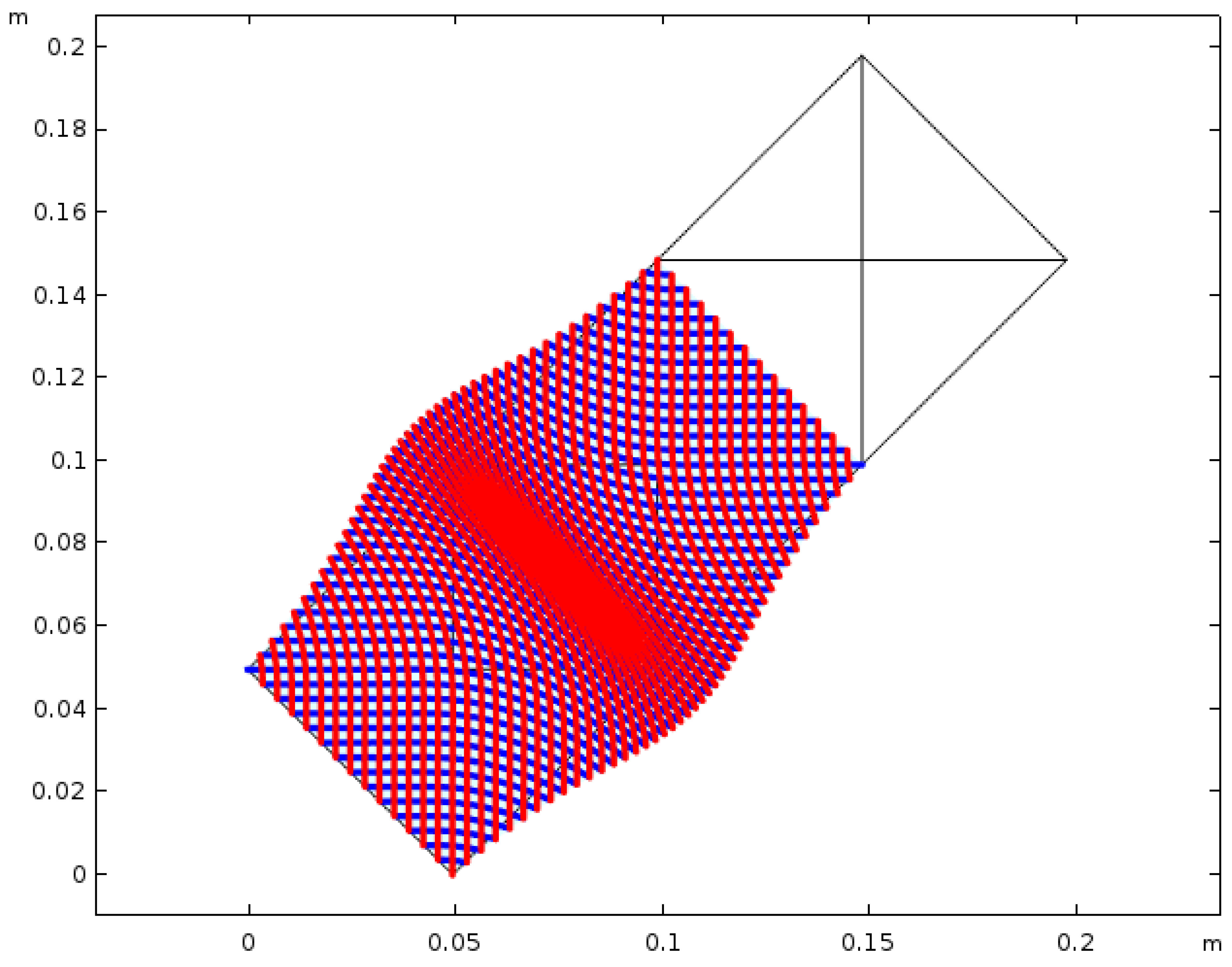
Figure 11.
Fibers, cm—arbitrary parameter values: J, N/m, N/m.


Table 1.
Geometry and material properties of the fibers constituting both tested structures.
| Young Modulus | Size of Cross-Section | Cross-Section Area | Second Moment of Area |
|---|---|---|---|
| (Pa) | (m) | (m2) | (m4) |
Table 2.
Distance between two adjacent fibers of the same family.
| Specimen | 1 | 2 |
|---|---|---|
| (m) |
© 2020 by the authors. Licensee MDPI, Basel, Switzerland. This article is an open access article distributed under the terms and conditions of the Creative Commons Attribution (CC BY) license (http://creativecommons.org/licenses/by/4.0/).
Share and Cite
MDPI and ACS Style
Tran, C.A.; Gołaszewski, M.; Barchiesi, E. Symmetric-in-Plane Compression of Polyamide Pantographic Fabrics—Modelling, Experiments and Numerical Exploration. Symmetry 2020, 12, 693. https://doi.org/10.3390/sym12050693
AMA Style
Tran CA, Gołaszewski M, Barchiesi E. Symmetric-in-Plane Compression of Polyamide Pantographic Fabrics—Modelling, Experiments and Numerical Exploration. Symmetry. 2020; 12(5):693. https://doi.org/10.3390/sym12050693
Chicago/Turabian StyleTran, Chuong Anthony, Maciej Gołaszewski, and Emilio Barchiesi. 2020. "Symmetric-in-Plane Compression of Polyamide Pantographic Fabrics—Modelling, Experiments and Numerical Exploration" Symmetry 12, no. 5: 693. https://doi.org/10.3390/sym12050693
Note that from the first issue of 2016, this journal uses article numbers instead of page numbers. See further details here.