Article

Analytical Technique Leveraging Processing Gain for Evaluating the Anti-Jamming Potential of Underwater Acoustic Direct Sequence Spread Spectrum Communication Systems

1
College of Naval Architecture and Ocean Engineering, Naval University of Engineering, Wuhan 430033, China
2
Qingdao Innovation Research Center, Harbin Engineering University, Qingdao 266000, China
*
Author to whom correspondence should be addressed.
Symmetry 2023, 15(9), 1710; https://doi.org/10.3390/sym15091710
Submission received: 11 August 2023 / Revised: 30 August 2023 / Accepted: 5 September 2023 / Published: 6 September 2023

Abstract

:
This study proposes an analytical technique underpinned by processing gain to evaluate the anti-jamming potential of an underwater acoustic direct-sequence spread-spectrum (DSSS) communication system that employs a short-period pseudo-noise (PN) sequence. The processing gain comes from the symmetry of the coding, which provides a mechanism for separating desired signals from unwanted ones, and the apparent randomness of the coding, which suppresses interference and noise in the system. The robustness of such a system against wideband interference, partial-band jamming, and single-frequency interference is emulated. Outcomes suggest that, in comparison to a standard binary phase shift keying (BPSK) system, the DSSS system’s ability to resist wideband interference is limited, with only a marginal increase in immunity performance of approximately 0.5 dB. Contrarily, it suppresses partial-band jamming effectively, with the suppression level dependent on the interference bandwidth and its relative position concerning the signal carrier frequency. The influence of single-frequency interference on system performance depends similarly on its relative location relative to the signal carrier frequency. In all situations where the interference frequency offset is an integer multiple of the bit bandwidth, the system exhibits the worst performance when the frequency offset equals the bit bandwidth. Upon comparing resistance levels to identical power interferences targeted at the signal carrier frequency, our system demonstrates optimal resilience to single-frequency interference. In concordance with the empirical findings, the simulated results substantiate both the effectiveness and practicability of the proposed analytical method based on processing gain. Subsequently, this study contributes a novel perspective for evaluating the anti-jamming potential of DSSS systems.

1. Introduction

Spread-spectrum communication is widely used in commercial and military applications because of its strong anti-jamming capability, low interception probability, and excellent concealment ability. In particular, DSSS communication is simple in principle, with low structural requirements and excellent transmission quality, making it suitable for communication in complex underwater acoustic channels. The feature of interference immunity in DSSS communication systems is largely due to their use of PN sequences that enable the system to correlate signals even in the presence of significant noise. Symmetry plays a crucial role in these DSSS systems, specifically in the design and application of the spreading sequence codes. Often, these sequences need to be orthogonal or nearly orthogonal to each other, which means that they bear no correlation to one another. This orthogonality or symmetry can help improve the system’s performance by minimizing interference from other sources. Several studies have focused on the characteristics of DSSS systems in radio applications. The processing gain of DSSS systems under different interferences was studied in [1,2,3,4,5]. The effect of narrow-band interference on a DSSS system was found to be primarily related to the interference location in [6,7]. In [8,9,10,11,12,13,14,15], the transmission performance of DSSS systems under different interference conditions was examined via simulation. The anti-jamming performance of a DSSS system was investigated in terms of the bit error rate (BER) in [16,17,18,19,20,21,22,23,24]. Further, Namdar, M. et al. investigated the performance of anti-jamming in multi-input, multi-output cognitive radio networks [25].
In the analysis of the anti-jamming performance of DSSS systems in radio applications, the spreading code is usually approximated as an infinitely long code for processing because of the high frequency and large available bandwidth of radio communication. The system’s performance is typically most affected when the interference targets the signal carrier. Compared with radio communication, the carrier frequency in underwater acoustic communication is low, and the available bandwidth is generally narrow. Short-period PN sequences must typically be used to ensure timely communication. Research theory based on the anti-jamming capability of the radio DSSS system is not fully applicable to underwater acoustic communication. Furthermore, research on anti-jamming in underwater acoustic communication remains limited [26,27]. Therefore, investigating the anti-jamming problem in underwater acoustic communication is crucial to improving communication quality and extending the applicability of DSSS systems in engineering practice.
DSSS systems have different inhibition capabilities for different interference modes. According to the bandwidth of the interference signal relative to that of the spread spectrum signal, the interference can be primarily divided into wideband interference, partial-band jamming, and single-frequency interference.
The main contributions of this paper are summarized as follows:
  • This study proposes an analytical technique underpinned by processing gain to evaluate the robustness of an underwater acoustic DSSS communication system against wideband interference, partial-band jamming, and single-frequency interference, contributing a novel perspective for evaluating the anti-jamming potential of DSSS systems.
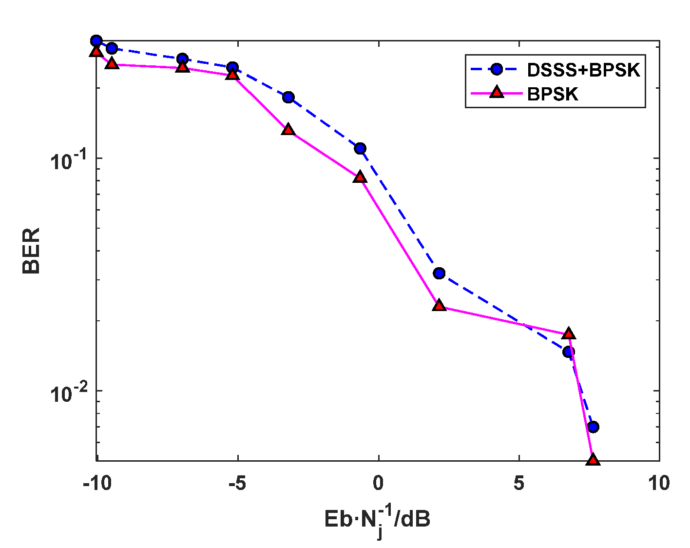
  • The proposed analytical method’s robustness and applicability were corroborated through extensive simulations and rigorous testing procedures. Outcomes suggest that, in comparison to a standard BPSK system, the DSSS system’s ability to resist wideband interference is limited, with only a marginal increase in immunity performance of approximately 0.5 dB. Contrarily, it suppresses partial-band jamming effectively, with the suppression level dependent on the interference bandwidth and its relative position concerning the signal carrier frequency. The influence of single-frequency interference on system performance depends similarly on its relative location relative to the signal carrier frequency. In all situations where the interference frequency offset is an integer multiple of the bit bandwidth, the system exhibits the worst performance when the frequency offset equals the bit bandwidth. Upon comparing resistance levels to identical power interferences targeted at the signal carrier frequency, our system demonstrates optimal resilience to single-frequency interference.
This manuscript is structured as follows: Section 2 elucidates the analytical methodology and derives key theoretical expressions to model the anti-interference capacity of DSSS systems utilizing short-period PN sequences. Following this, Section 3 encompasses a Monte Carlo simulation to provide a qualitative analysis of DSSS performance. Subsequently, Section 4 showcases test results, thus affirming both the validity and suitability of the proposed method for analyzing the anti-jamming capability within underwater acoustic DSSS communication systems. Finally, the paper culminates in Section 5, with concluding remarks.

2. Method

This section describes the signal model and the analysis methods based on processing gain in detail.
The principle of the receiver in a DSSS system is depicted in Figure 1. In this paper, the basic binary phase shift keying (BPSK) modulation is used, and the received signal r(t) in the figure can be represented as
r t = s t + n t + j t
where s(t) is the DSSS signal with coded information, n(t) denotes the additive Gaussian white noise with mean value 0 and bilateral power spectral density N0/2, and j(t) is the interference signal, which in this paper includes wideband interference, partial-band jamming, and single-frequency interference. The useful signal s(t) can be expressed as [21] (p. 6).
s t = 2 P d t c t cos 2 π f 0 t + φ 0
where P is the signal power, d(t) is a random value (±1), Tb is the bit width of the information sequence to be decoded, c(t) takes the period N, Tc is the chip width of the pseudo-random sequence (±1; Tc = Tb/N), f0 is the received signal carrier frequency, and φ0 is the random phase. The power spectral density function [21] (p. 54) of the PN sequence c(t) is
S c f = 1 N 2 δ f + N + 1 N 2 n = n 0 sin c 2 n N δ f n R b
where Rb is the information bit rate (Rb = 1/Tb). From Equation (2), it is known that the power spectrum of the pseudo-random sequence is a discrete line spectrum with spectral line interval Rb. For notational convenience, sinc2(n/N) is considered as Ψ(n), which is an even function. In the analysis of the anti-jamming performance of the DSSS system, the receiver is typically assumed to default to the state in which the synchronization of the carrier and the spreading code are obtained, namely f ^ d = 0, T ^ d = 0 and φ0= φ ^ 0 . After processing by the receiver, the power of the output useful signal is [28]
P s = R b R b 2 P 2 S d f H f 2 d f
where Sd(f) is the power spectral density function of the data signal d(t), and |H(f)|2 is the low-pass filter transfer function. To ensure that the signal can pass through the filter without loss, the passband bandwidth of the baseband low-pass filter should be equal to the bit bandwidth, as follows:
H f = 1 2                 f R b 0                     f > R b
As d(t) is a bilevel waveform function that takes values of +1 and −1 with equal probability, it satisfies S d ( f ) d f = 1. Hence, the power of the output signal is
P s = R b R b 2 P 2 H f 2 d f = P

2.1. Wideband Interference

If v1(t) is the wideband interference passing through the band-pass filter at the front end of the receiver, it can be expressed as follows:
v 1 t = n 1 t cos 2 π f 0 t + φ 0
where n1(t) is the baseband interference signal with a mean value of zero. The two-sided power spectral density is
S n 1 f = N 1 2                           f R c 0                                 f > R c
The wideband interference power entering the receiver is
P v 1 = N 1 R c 2
After the receiver correlation process, the output wideband interference power spectral density of the low-pass filter is
P v f = R b R b S c f S n 1 f H f 2 d f
where Sc(f)∗Sn1(f) denotes the convolution of Sc(f) with Sn1(f).
S v f = S c f S n 1 f = N 1 2 1 N 2 + N + 1 N 2 n = N n 0 N Ψ n
Values in the range of 0.890–0.903 are considered for the term in the square brackets in Equation (10). Evidently, the power spectral density of the wideband interference falling into the low-pass filter is changed to approximately 0.9 times the original value after the despreading process. Moreover, the output wideband interference power of the receiver is calculated as follows:
P v = N 1 R b 2 N 2 1 + N + 1 n = N n 0 N Ψ n
The system processing gain for wideband interference is
G p = S N R out S N R in = N 3 1 + 2 N + 1 n = 1 N Ψ n

2.2. Partial-Band Jamming

The form of partial-band jamming is similar to that of wideband interference and is expressed as
v 2 t = n 2 t cos 2 π f 2 t + φ 2
where f2 is the center frequency of the narrow-band interference, φ2 is the narrow-band interference phase, which is uniformly distributed in [0, 2π], and n2(t) is the baseband interference signal with a single-sided bandwidth of Bj (Bj < Rc). The two-sided power spectral density is
S n 2 f = N 2 2                         f B j 0                               f > B j
Similar to wideband interference, the power of interference entering the receiver is
P v 2 = N 2 2 B j
To simplify the analysis, the interference frequency offset is assumed to be an integer multiple of the bit bandwidth Rb and ∆f = kRb (k is an integer, called the frequency offset coefficient; |k| < N). Two cases—Bj Rb and Bj > Rb—are discussed.

2.2.1. Interference bandwidth Is Less Than the Bit Bandwidth (BjRb)

The following conditions are considered:
  • k = 0;
The power of the interference output by the receiver is
P v = P v 2 2 N 2 1 + N + 1 Ψ 1
The system’s processing gain is
G p = P / P v 2 P / P v = 2 N 2 1 + N + 1 Ψ 1
  • |k| = 1;
The power of the interference output by the receiver is
P v = P v 2 4 N 2 1 + N + 1 2 Ψ 1 + Ψ 2
The system’s processing gain is
G p = 4 N 2 1 + N + 1 2 Ψ 1 + Ψ 2
  • |k| > 1;
The power of the interference output by the receiver is
P v = N + 1 P v 2 4 N 2 Ψ k 1 + 2 Ψ k + Ψ k + 1
The system’s processing gain is
G p = 4 N 2 N + 1 Ψ k 1 + 2 Ψ k + Ψ k + 1

2.2.2. Interference Bandwidth Greater Than the Bit Bandwidth (Bj = mRb, m Is Called the Unilateral Bandwidth Coefficient; 1 < m < N − |k|)

The following conditions are considered.
  • |k| < ⌊m⌋ (⌊·⌋ denotes rounding down);
The power of the interference output by the receiver is
P v = N 2 R b 8 N 2 2 + N + 1 P m k
The system’s processing gain is
G p = 4 N 2 m 2 + N + 1 P m k
where P(⌊m⌋|k) is a function related to ⌊m⌋ and k, which can be expressed as
P m k = i = 1 m k i 0 m + k 1 2 Ψ i + Ψ m k + Ψ m + k L + Ψ m k + 1 + Ψ m + k + 1 l
where m-k = ⌊m⌋ − k, m+k = ⌊m⌋ + k, L = (Bj − ⌊mRb + Rb)/Rb, l = (Bj − ⌊mRb)/Rb.
  • |k| = ⌊m⌋;
The power of the interference output by the receiver is
P v = N 2 R b 8 N 2 L + N + 1 P m k
The system’s processing gain is
G p = 4 N 2 m L + N + 1 P m k
  • |k| = ⌊m⌋ + 1;
The power of the interference output by the receiver is
P v = N 2 R b 8 N 2 l + N + 1 P m k
The system’s processing gain is
G p = 4 N 2 m l + N + 1 P m k
  • |k| > ⌊m⌋ + 1;
The power of the interference output by the receiver is
P v = N + 1 N 2 R b 8 N 2 P m k
The system’s processing gain is
G p = 4 N 2 m N + 1 P m k

2.3. Single-Frequency Interference

The single-frequency interference is expressed as
j t = 2 J cos 2 π f j t + φ j
where J is the power of interference, fj and φj are the interference frequency and interference phase, respectively, and φj is uniformly distributed in [0, 2π].
The power of the interference output by the receiver can then be expressed as
P j = J 4 R b R b S c f Δ f + S c f + Δ f d f
where ∆f = fj − f0, denoting the interference frequency offset.

2.3.1. ∆f = kRb (k Is an Integer; |k| ≤ N)

When the interference frequency offset is an integer multiple of the bit bandwidth, Rb, the output power of single-frequency interference after passing through the low-pass filter is
P j = J 4 R b R b S c f Δ f + S c f + Δ f d f
The processing gain is
G P = P s / P j P / J = 2 N 2                                   k = 0 2 N 2 N + 1 Ψ k                 k 0
Since the sinc2 function is monotonically decreasing over a given range, the system has the minimized gain in handling single-frequency interference for |k| = 1.

2.3.2. ∆f = rRb (r Is a Non-Integer; |r| < N)

When the interference frequency offset is not an integer multiple of the bit bandwidth Rb, two spectral lines of single-frequency interference fall into the low-pass filter and affect subsequent symbol judgments. This gives rise to two cases.
  • |r| < 1;
The power of the interference output by the filter is
P j = J 2 N 2 1 + N + 1 Ψ 1
The system processing gain is
G p = 2 N 2 1 + N + 1 Ψ 1
  • 1 < |r| < N;
The power of the interference output by the filter is
P j = N + 1 I 2 N 2 Ψ r + Ψ r
The system’s processing gain is
G p = 2 N 2 N + 1 Ψ r + Ψ r
where ⌈·⌉ denote rounding up.

3. Simulation Results and Analysis

To verify the accuracy of the proposed method based on the processing gain for determining the anti-jamming capability of an underwater acoustic DSSS system, a Monte Carlo simulation is performed to qualitatively analyze the performance of the DSSS system using a short-period PN sequence. The BER is used in the simulation to measure the interference immunity of the DSSS system; the better the interference immunity, the lower the BER.

3.1. Simulation Scheme

The simulation model is developed in MATLAB. The propagation loss of hydroacoustic signals increases with the increase in frequency, and the lower the frequency, the longer the effective propagation distance of hydroacoustic signals underwater. In addition, due to the limitation of the bandwidth of the transducer, hydroacoustic communication mainly uses low-frequency signals. However, at low frequencies, the bandwidth available for communication is very limited, which makes it difficult for hydroacoustic communication to simultaneously meet the two major demands of high speed and long distance. Taking the above into account, this paper sets the simulation parameters as follows: The carrier frequency f0 is 1200 Hz, the bit rate Rb is 40 bit/s, the spreading code is an m-sequence with a period of 15, the chip rate Rc is 600 chip/s, and in order to eliminate inter-code crosstalk, the sampling frequency is greater than the Nyquist sampling frequency, which is set to 19,200 Hz, i.e., 16 sampling points per carrier cycle. In fact, after many trial calculations, it was found that the choice of parameters such as frequency carrier does not affect the objective law of anti-interference performance of DSSS systems.
Compared to radio communication, hydroacoustic communication embodies unique characteristics, including significant propagation loss, considerable ambient noise, a multipath effect, and channel instability. These elements cooperatively result in a low environmental SNR within the realm of hydroacoustic communications. Furthermore, the allure of systems utilizing low input SNR in acoustic communications stems from numerous practical applications. For example, acoustic signals that are substantially weaker than the background noise, such as those with an SNR of −8 dB within the signal band, present substantial challenges for detection by an unvigilant listener. Without prior knowledge of the signal’s structure, decoding noise-like signals can prove difficult. Deploying low-Input-SNR signals at the receiver end has been purported to offer both a low probability of interception (LPI) and a correspondingly low probability of detection (LPD). With this in mind, this study endeavors to delve into environments characterized by low SNRs.
The objective of the simulation is to verify the communication capability of the DSSS system under different interference modes and to determine the effect of the interference bandwidth, interference frequency offset, and other factors on the anti-jamming performance of the system. When using the model shown in Figure 1, the working conditions listed in Table 1 are set for different interference modes. The BER of the BPSK modulation system is 10−4 when the signal-to-noise ratio of the additive white Gaussian noise (AWGN) is 8.4 dB for working conditions 7–9. Interference significantly affects the synchronization of the spread spectrum system and subsequently severely deteriorates system performance. Therefore, accurate synchronization is assumed to be achieved in the simulation.

3.2. Analysis of Simulation Results

3.2.1. Wideband Interference

Figure 2 shows the BER curves of the DSSS-BPSK system and the BPSK system under wideband interference for working condition 1. Compared with the conventional BPSK system, the BER of the DSSS system decreases slightly, which indicates that although the DSSS system has a certain system gain to wideband, the gain is limited, and the system performance is improved by less than 0.5 dB when the BER is of the order of 10−3.

3.2.2. Partial-Band Jamming

Figure 3a,b depict the inhibition effect of the system when subjected to partial-band jamming under working conditions 2 and 3. Evidently, the BER of the DSSS-BPSK system is much lower than that of the BPSK system at the same signal-to-noise ratio, indicating that the DSSS technique effectively inhibits partial-band jamming when the interference targets the signal carrier frequency.
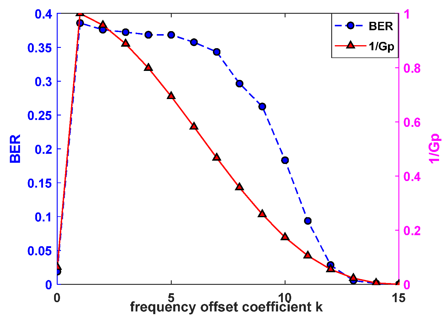
  • Effect of interference frequency offset on the anti-jamming performance of the DSSS system;
Figure 4a,b illustrate the shifts in BER and processing gain due to interference frequency offset under working conditions 4 and 5, respectively. These shifts occur when the interference bandwidth is either smaller or larger than the bit bandwidth. Figure 4a shows that if the interference bandwidth is less than the bit bandwidth, BER and the reciprocal of processing gain (interference power output by the filter) exhibit a similar trend correlating with changes in frequency offset: initial augmentation followed by diminution as frequency offset increases. They both peak when the frequency offset equals twice the bit bandwidth. This points towards maximum interference power within the filter bandwidth at this juncture, severely impacting system performance. Meanwhile, Figure 4b reveals that except for zero-frequency offset, an escalating interference frequency offset prompts a diminishing system BER and reciprocal processing gain when interference bandwidth exceeds bit bandwidth. This depicts the dwindling influence of interference on the system once the interference center deviates from the signal carrier frequency.
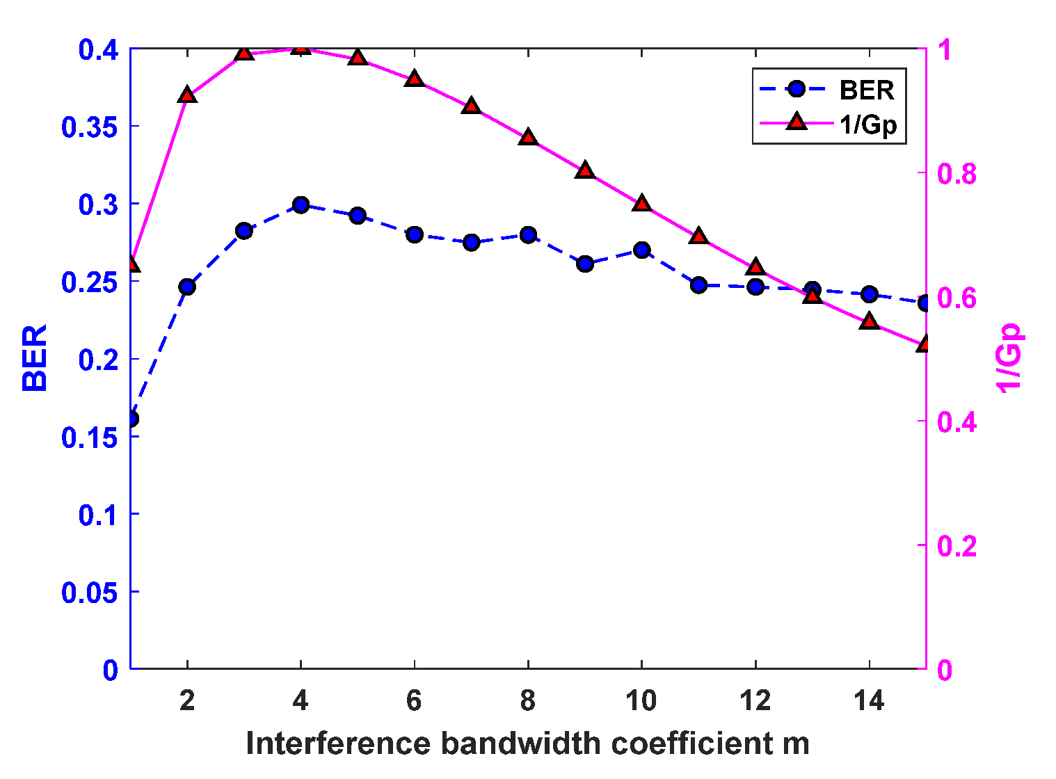
  • Effect of interference bandwidth on the anti-jamming performance of the DSSS system;
The above-mentioned results demonstrate that the effect of partial-band jamming on the system is related to both the interference bandwidth and the interference location. This section discusses the effect of interference bandwidth on the anti-jamming performance of the system, considering an interference frequency offset of zero as an example.
Figure 5 outlines the variation curves for the system BER and the reciprocal of processing gain against the interference bandwidth for working condition 6. If the interference bandwidth meets or surpasses the bit bandwidth, the reciprocal system processing gain undergoes an initial climb followed by a decline. This indicates a similar initial rise and subsequent fall in system output interference power. Hence, partial-band jamming at a distinct bandwidth has the utmost impact on the system. This fluctuation pattern synchronizes with the system’s BER variation trend. When the frequency offset is null and the interference bandwidth reaches quadruple the bit bandwidth, anti-jamming performance sinks to its lowest. As a result, when partial-band jamming aligns with the signal carrier frequency, system performance severely degrades at a specific interference bandwidth.

3.2.3. Single-Frequency Interference

Comparing the BER for conventional BPSK systems to DSSS-BPSK systems facilitates an analysis of spread spectrum technology’s buffering effect against single-frequency interference. Figure 6 encapsulates the system’s BER performance under working condition 7. Evidently, the DSSS-BPSK system’s BER is significantly lower than the BPSK system for the same SIR, confirming the accomplishment of effective curbs via the DSSS technique against single-frequency interference aimed at the signal carrier.
Figure 7 mirrors the changes in BER and the reciprocal of processing gain relative to frequency offset under working condition 8. With the interference frequency offset as an integer multiple of the bit bandwidth, BER and reciprocal processing gain reflect a consistent trend along with the changing frequency offset—both an initial increase followed by a decrease. Both reach their apex when the frequency offset equals the bit bandwidth. In such a scenario, the interference power infiltrating the filter attains its maximum potency, subsequently causing significant effects on the system.

3.2.4. Anti-Jamming Performance of the DSSS System under Different Interference Modes

Our data analysis reveals discrepancies in the DSSS system’s anti-jamming efficacy among different interference modes. More precisely, the BER varies at the identical SIR. The system performance was gauged via simulation for three types of interference signals, extracting BER versus SIR curves for various interference modes as outlined in Figure 8. The simulation parameters used align with working condition 9 as shown in Table 1.
Figure 8 illustrates similar BER versus SIR curves for the DSSS-BPSK system across different interference modes. Nonetheless, at an equivalent SIR, the system registers the minimum BER in the presence of single-frequency interference. When setting the threshold BER at 10−3, the system reaches this value at an SIR of −15 dB with single-frequency interference. In contrast, wideband interference compels the system to arrive at the same threshold BER but at a relatively higher SIR of −6 dB. Further, partial-band jamming, having interference bandwidths of 40 Hz and 160 Hz, takes the system to the threshold BER at SIR of −7 dB and −2 dB respectively, both superior by 8 dB and 13 dB to that of single-frequency interference. The simulation findings imply that while the DSSS system exhibits optimal inhibitory capacity against single-frequency interferences, it only has limited resistance towards partial-band jamming (considering wideband interference as a specific instance of partial-band jamming). Hence, integrating an anti-narrowband jamming module before receiver-related processing in practical applications can enhance the system’s jamming resistance.

4. Test Results and Analysis

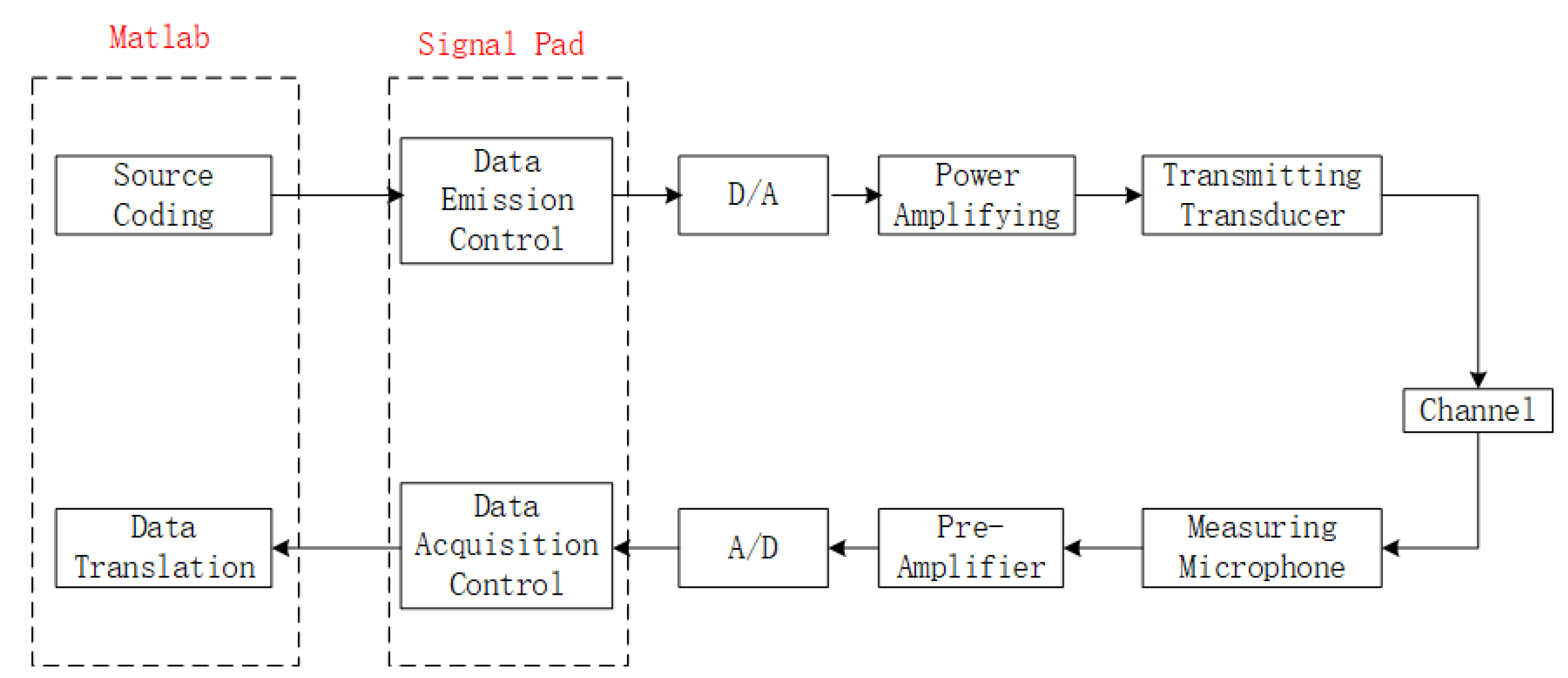
4.1. Test Device and Principle
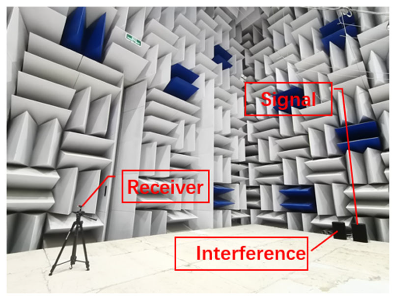
The validity and feasibility of the introduced method for determining the anti-jamming capacity of underwater acoustic DSSS communication systems based on processing gain were tested using a specially designed platform in an anechoic wind tunnel. The test principle and platform are illustrated in Figure 9 and Figure 10, respectively. Key components of this platform included a PXI machine outfitted with Signal Pad measurement and control software, a signal generator, a power amplifier, speakers, and measurement microphones housed within a fully anechoic chamber. This chamber encompassed a spatial volume measuring 11.69 m long by 8.3 m wide. It was topped and surrounded with metal anechoic tip splitting and floored with acoustic panels with low-frequency cut-off frequencies down to 50 Hz, eliminating any strong reflected signals at the receiving end under full anechoic conditions. An array of 8NM52 non-directional loudspeakers with a bandwidth range of 217–6000 Hz was installed to meet specific working frequency band requirements, and non-directional AWA14423 measurement microphones were utilized at the receiving end. Notably, the SIR was primarily governed by transducer transmitting power, considering the space constraints of the testing environment.
During the operation of the test bench, the signal was coded using MATLAB to generate the data to be emitted, which was stored in the PXI machine with the PXIe-6368 integrated card (NI, USA). The signal generator module in Signal Pad was then used to send the emitted signal to the power amplifier (TAT-D2000) via one of the channels in the D/A card before being emitted by the corresponding loudspeaker. At the receiving end, the signal received by the measurement microphone was first amplified and filtered using a preamplifier (AWA14604), and then A/D was converted using a data collector matched with the PXIe-6368 D/A card. The converted signal was received and stored by the Signal Pad data signal module.

4.2. Test Scheme

According to the simulation scheme, the following working conditions were employed in the test: The carrier frequency f0 was 1200 Hz, the bit rate Rb was 40 bit/s, the spreading code was selected as an m-sequence with a period of 15, the spreading chip rate Rc was 600 chip/s, and the sampling rate fs was 19,200 Hz. The working conditions are listed in Table 1.

4.3. Analysis of Test Results

4.3.1. Wideband Interference

Figure 11 illustrates the BER curves of the DSSS-BPSK system and the BPSK system under the influence of wideband interference. This operates under conditions identical to those of working condition one utilized in the simulation, with the exception that the signal-to-interference ratio ranges from −10 dB to 10 dB. There is no significant order of magnitude disparity between the BER of both the DSSS and BPSK systems under these test circumstances. This suggests that DSSS technology does not effectively suppress wideband interference in comparison to traditional BPSK technology. Furthermore, due to inherent aspects of the testing apparatus (such as the frequency drift of electronic components), room echo, and the impact of weak multipath, precise synchronization is not obtained by either system. However, the effect of synchronization appears more pronounced within the DSSS system. The DSSS system also experiences influence from the loudspeaker’s non-flat frequency response curve within the working frequency range. Consequently, the BER values acquired during the tests are noticeably amplified compared to those from the simulations, with the DSSS system demonstrating a slightly higher BER than the BPSK system.

4.3.2. Partial-Band Jamming

Figure 12 depicts the BER trends for both DSSS-BPSK and BPSK systems under similar interference conditions. In tests (a) and (b), the targeted interference is centered at the signal carrier with one-sided bandwidths for partial-band jamming, respectively fixed at 30 Hz (0.75Rb) and 160 Hz (4Rb). These parameters are based on the second and third working conditions specific to the simulation study. The figure indicates that when the interference bandwidth is considerably less than the spreading bandwidth, the BER in traditional BPSK remains largely constant despite an upsurge in SIR and remains relatively high. Conversely, the DSSS-based system’s BER is significantly lower compared to its BPSK counterpart and shows a marked reduction as SIR increases. When handling more extensive bandwidth interferences, the DSSS system exhibits some benefits over the conventional BPSK system. Still, these advantages are not as pronounced as those observed under low-bandwidth interference conditions. This suggests that when interference targets the signal carrier’s center, DSSS performance enhancement heightens when the interference focus narrows. However, as the interference bandwidth widens, nearing wideband interference, this system performance advantage decreases progressively. It is noteworthy that the experimentally obtained BER for the DSSS system is notably higher than that derived from simulation outcomes.
  • Effect of interference frequency offset on the anti-jamming performance of the DSSS system
The SIR is set at −10 dB for the duration of the test, in alignment with parameters defined by working conditions 4 and 5 from the simulation. Given that interference strength relies heavily on the frequency response curve of the transmitting transducer, continuous readjustment of the power dial is necessary. To maintain accurate results, effort is taken to ensure the SIR remains consistently near −10 dB with marginal errors not exceeding 0.3 dB.
Figure 13a plots the variation of the system BER with the interference frequency offset when the interference bandwidth is smaller than the bit bandwidth (0.75Rb). Here, the BER initially increases and then decreases with an increase in the frequency offset, reaching its maximum when the frequency offset is twice the bit bandwidth, which is congruent with earlier simulation results. Conversely, Figure 13b illustrates the fluctuations in BER with variations in interference frequency offset when the interference bandwidth is much larger than the bit bandwidth (4Rb). The trend seen here is a decline in system BER as the interference frequency offset swells, suggesting that disturbance to the system diminishes as interference shifts away from the signal’s central frequency. In conjunction with Figure 4, it can be seen that the effect of partial band interference on the performance of the DSSS system is related to both the location of the interference relative to the signal carrier frequency as well as the size of the bandwidth.
  • Effect of interference bandwidth on the anti-jamming performance of the DSSS system
In the next part of the test, the case in which interference targets the signal carrier is considered as an example to analyze the effect of interference bandwidth on the anti-jamming performance of the system, with the SIR set as in the previous test in this research.
Figure 14 depicts the variability of system BER with the interference bandwidth when the interference frequency offset is zero. The test parameters are set according to scenario 6 of the simulation work state, except for adjusting the SIR to −10 dB and increasing the condition of interference frequency bandwidth coefficient to zero (single-frequency interference). As observed, when the frequency offset equals zero, the loudspeaker’s frequency response curve affects the power spectral density within the bandwidth range, causing considerable bandwidth interference. As a result, it is not entirely congruous with Gaussian noise characteristics, causing irregularities in the BER curve. Despite this, the system’s BER exhibits an overarching trend of first rising and then falling with each increment of bandwidth. The system’s resistance to interference is most compromised when the interference bandwidth is four times the bit bandwidth.
Additionally, both single-frequency interference and wideband interference can be considered forms of partial-band jamming, characterized by bandwidth coefficients of 0 and 15, respectively. Thus, Figure 14 illustrates that when interference is targeted at the signal carrier frequency, the system demonstrates heightened resistance to single-frequency interference alongside a constrained diminution of partial-band jamming under equivalent interference power levels.

4.3.3. Single-Frequency Interference

Single-frequency interference can be considered partial-band jamming with an infinitely narrow bandwidth. Therefore, the test results presented in Figure 13a for partial-band jamming also apply to single-frequency interference and will not be elaborated further in this paper.
From a qualitative analysis perspective, the trends noted in the system’s anti-interference performance, as gleaned from the empirical tests, resonate with the simulation results. Due to inherent characteristics of the testing apparatus, including aspects such as frequency drift among electronic components, environmental echoes, and the influence of weak multipath phenomena, the system does not achieve exact synchronization. Furthermore, considering the broadband nature of the signal examined in this paper and due to the impact of the frequency response curve of the loudspeaker, the actual signal emission experiences a certain level of distortion. When evaluating from a quantitative standpoint, the BER derived from the experiment is marginally higher than that of the simulated BER. Nonetheless, the experimental results are in close alignment, magnitude-wise, with the simulation outcomes, thereby validating the reliability of the test results.

5. Discussion

BER is used in simulation and testing to measure the immunity of a DSSS system to interference. For the same system, the higher the processing gain, the more the system attenuates the interference, the lower the interference energy entering the receiver low-pass filter, the less impact on subsequent symbol judgment, and the lower the system BER.
In previous studies, when analyzing the anti-jamming performance of DSSS systems, spreading codes are usually approximated as infinite-length codes for processing, and it is usually assumed that when the interference power is the same, the more the interference is concentrated in the center of the signal carrier, the greater the impact on the system.
This paper elucidates, through theoretical derivations, simulations, and empirical studies, the impact of interference sources on DSSS systems utilizing finite long-period pseudo-random sequences. Contrary to assumptions, it is not the interference sources proximate to the heart of the signal carrier—those rendered with narrow bandwidths—that significantly affect the system owing to the ‘notch’ phenomenon in the power spectral density of center-frequency spread-spectrum codes. In contrast, in the case of partial-band interference (both broadband and single-frequency interference fall into this category), it has been shown that there are significant and horrible bandwidth and frequency deviations that can significantly degrade the system’s immunity to interference.

6. Conclusions

This paper introduces a methodology for determining the anti-jamming capability of an underwater acoustic DSSS communication system, guided by processing gain. The system’s anti-jamming performance is scrutinized under different conditions, including wideband interference, partial-band jamming, and single-frequency interference. Conclusions were drawn based on simulation and testing results:
  • The DSSS system demonstrates limited capacity to mitigate wideband interference. Relative to the BPSK system that does not incorporate DSSS technology, the anti-jamming performance of the DSSS system proves superior by approximately 0.5 dB.
  • The ability of the DSSS system to suppress partial-band jamming correlates to both the location of interference in relation to the signal carrier frequency and its bandwidth. We find that when the interference directly targets the signal carrier frequency, there is an interference bandwidth that minimizes system performance.
  • The inhibition ability of the DSSS system for single-frequency interference is related to the location of the interference relative to the signal carrier frequency. In all cases where the interference frequency offset is an integer multiple of the bit bandwidth, the system performance is worst when the frequency offset is equal to the bit bandwidth.
  • Upon comparing resistance levels to identical power interferences targeted at the signal carrier frequency, the DSSS system demonstrates optimal resilience to single-frequency interference.
Notably, results obtained from simulations are congruent with test outcomes. This indicates the practical feasibility and efficacy of the proposed method and suggests an innovative pathway for choosing processing methods and parameters during the design process of underwater acoustic DSSS communication systems.
In light of these findings, we propose several future research trajectories. To start with, varying strategies should be adopted to mitigate different types of interference. Wideband interference, for example, should be tackled in conjunction with additive Gaussian white noise. Partial-band jamming should be addressed from bandwidth and frequency offset perspectives. Meanwhile, single-frequency interference could be managed by adjusting its frequency offset. Moreover, there is a need for broader validation of the proposed method within the domain of underwater acoustics.

Author Contributions

Conceptualization, X.W., and Q.Z.; methodology, X.W.; formal analysis, X.W.; writing—original draft preparation, X.W.; supervision, Q.Z. All authors have read and agreed to the published version of the manuscript.

Funding

This research was funded by the National Natural Science Foundation of China, grant number 52071334.

Institutional Review Board Statement

Not applicable.

Informed Consent Statement

Not applicable.

Data Availability Statement

The data presented in this study are available on request from the corresponding author.

Acknowledgments

We acknowledge the equal contribution of all the authors. We thank the editors and the reviewers for their useful comments that improved this paper.

Conflicts of Interest

The authors declare no conflict of interest.

References

  1. Li, K.H.; Milstein, L. On the optimum processing gain of a block-coded direct-sequence spread-spectrum system. IEEE J. Sel. Areas Commun. 1989, 7, 618–626. [Google Scholar] [CrossRef]
  2. Schilling, D.; Milstein, L.; Pickholtz, R.; Brown, R. Optimization of the processing gain of and m-ary direct sequence spread spectrum communication system. IEEE Trans. Commun. 1980, 28, 1389–1398. [Google Scholar] [CrossRef]
  3. Ma, W.; Wang, J.; Shen, Y.; Tang, Y. The maximum processing gain of the spreading signal in multipath fading channels. In Proceedings of the Third International Conference on Communications and Mobile Computing, CMC 2011, Qingdao, China, 18–20 April 2011. [Google Scholar] [CrossRef]
  4. Poberezhskiy, Y. Generalization of processing gain definition and selection of spread spectrum signals. In Proceedings of the MILCOM 2002, Anaheim, CA, USA, 7–10 October 2002. [Google Scholar] [CrossRef]
  5. Chunhui, B.A.I. Research for anti-jamming capability of direct sequence spread spectrum communications. Ship Electron. Eng. 2019, 39, 55–58. [Google Scholar] [CrossRef]
  6. Hu, B.; Hu, X.; Yu, X. Analysis of influence of narrowband interference at different frequency locations on DSSS communication performance. Signal Process. 2005, 05, 548–550. [Google Scholar]
  7. Tan, W.; Feng, L.; Wang, B. Analysis of influencing factors of DSSS against narrow-band interference. Mod. Electron. Tech. 2010, 33, 4. [Google Scholar] [CrossRef]
  8. Dai, W.; Qiao, C.; Wang, Y.; Zhou, C. Improved anti-jamming scheme for direct-sequence spread-spectrum receivers. Wirel. Commun. 2015, 52, 161–163. [Google Scholar] [CrossRef]
  9. Yousaf, A.; Loan, A. Effect of jamming technique on the performance of direct sequence spread spectrum modem. In Proceedings of the 13th International Conference on Advanced Communication Technology (ICACT2011), Gangwon, Republic of Korea, 13–16 February 2011. [Google Scholar]
  10. Tikhomirov, A.; Omelvanchuk, E.; Semenova, A.; Smirnov, A.; Bakhtin, A. Direct sequence spread spectrum system noise and interference immunity analysis. In Proceedings of the 2018 IEEE East-West Design & Test Symposium (EWDTS), Kazan, Russia, 14–17 September 2018. [Google Scholar] [CrossRef]
  11. Alagil, A.; Alotaibi, M.; Liu, Y. Randomized positioning DSSS for anti-jamming wireless communications. In Proceedings of the 2016 International Conference on Computing, Networking and Communications (ICNC), Kauai, HI, USA, 15–18 February 2016. [Google Scholar] [CrossRef]
  12. Lakshmi, M.L.S.N.S.; Anudeepsagar, K.; Niranjanprasad. Analysis of DSSS performance under communication-jamming environment. In Proceedings of the 2014 International Conference on Electronics and Communication Systems (ICECS), Coimbatore, India, 13–14 February 2014. [Google Scholar] [CrossRef]
  13. Xie, D.G.; Wu, N.; Wang, C.; Liu, Q.F. Performance analysis and simulation of DSSS in tactical data link communication system. In Proceedings of the 2012 6th Asia-Pacific Conference on Environmental Electromagnetics (CEEM), Shanghai, China, 6–9 November 2012. [Google Scholar] [CrossRef]
  14. Qu, X.; Li, W. Simulation and analysis of DS-SS anti-jamming performance based on VHDL. In Proceedings of the 2012 International Conference on Industrial Control and Electronics Engineering, Xi’an, China, 23–25 August 2012. [Google Scholar] [CrossRef]
  15. Liu, Y.; Ning, P.; Dai, H.; Liu, A. Randomized differential dsss: Jamming-resistant wireless broadcast communication. In Proceedings of the INFOCOM 2010, 29th IEEE International Conference on Computer Communications, Joint Conference of the IEEE Computer and Communications Societies, San Diego, CA, USA, 15–19 March 2010. [Google Scholar] [CrossRef]
  16. Cai, C.; Shi, B.; Xu, K. Performance analysis of DSSS system under single tone and partial band interference. Aerosp. Electron. Countermeas. 2019, 35, 5. [Google Scholar]
  17. Kang, L.; Shao, Y. Research on anti-jamming function of direct sequence spread spectrum (DS-SS) system. J. Gannan Norm. Univ. 2006, 27, 55–57. [Google Scholar] [CrossRef]
  18. Sklar, B. Digital communications. Fundamentals and applications. Hypertens. Res. Off. J. Jpn. Soc. Hypertens. 2012, 33, 177–180. [Google Scholar] [CrossRef]
  19. Gu, X.; Olafsson, S. On the accuracy of the Gaussian approximation for performance analysis of spread-spectrum channels. In Proceedings of the 14th IEEE Proceedings on Personal, Indoor and Mobile Radio Communications, 2003, PIMRC 2003, Beijing, China, 7–10 September 2003. [Google Scholar] [CrossRef]
  20. Batani, N. Performance analysis of direct sequence spread spectrum system with transmitted code reference. In Proceedings of the 32nd Midwest Symposium on Circuits and Systems, Champaign, IL, USA, 14–16 August 1989. [Google Scholar] [CrossRef]
  21. Peterson, R.; Borth, D.; Ziemer, R. Introduction to Spread-Spectrum Communications; Prentice-Hall: Englewood Cliffs, NJ, USA, 1995; pp. 327–354. [Google Scholar]
  22. Poisel, R. Modern Communications Jamming Principles and Techniques, 2nd ed.; Artech House: Norwood, MA, US, 2011; pp. 334–338. [Google Scholar]
  23. Zhou, Y.W.; Li, D.R.; Yang, Y.W. Anti-jamming performance analysis of disturbance signals of different interference patterns by DSSS technology. Command. Control. Simul. 2018, 40, 5. [Google Scholar] [CrossRef]
  24. Li, Z.D.; Tan, W.F.; Kang, C.B.; Cheng, J.S. Research on anti-interference ability of direct sequence spread spectrum system. J. Electron. Inf. Technol. 2021, 43, 116–123. [Google Scholar] [CrossRef]
  25. Namdar, M.; Basgumus, A.; Aldirmaz-Colak, S.; Erdogan, E.; Alakoca, H.; Ustunbas, S.; Durak-Ata, L. Iterative interference alignment with spatial hole sensing in MIMO cognitive radio networks. Ann. Telecommun. 2022, 77, 177–185. [Google Scholar] [CrossRef]
  26. Ma, L.; Fan, C.; Sun, W.; Qiao, G. Comparison of jamming methods for underwater acoustic dsss communication systems. In Proceedings of the 2018 2nd IEEE Advanced Information Management, Communicates, Electronic and Automation Control Conference (IMCEC), Xi’an, China, 25–27 May 2018. [Google Scholar]
  27. Liu, J.; Zhang, G.; Dong, Y.; Tang, J. Effect analysis of underwater acoustic DSSS communication system under jamming. Ship Sci. Technol. 2016, 38, 106–110. [Google Scholar]
  28. Tian, R.; Chi, Y. Spread Spectrum Communication, 2nd ed.; Tsinghua University Press: Beijing, China, 2014; pp. 35–36. [Google Scholar]
Figure 1. Receiver model of the DSSS communication system.
Symmetry 15 01710 g001
Figure 2. Simulation Results: Performance comparison between DSSS system and non−DSSS system under wideband interference.
Symmetry 15 01710 g002
Figure 3. Simulation Results: Performance comparison between DSSS system and non−DSSS system under narrowband interference. (a) Bj = 30 Hz. (b) Bj = 160 Hz.
Symmetry 15 01710 g003
Figure 4. Simulation Results: The influence of interference frequency offset on the anti-jamming performance of the system. (a) Bj = 30 Hz. (b) Bj = 160 Hz.
Symmetry 15 01710 g004
Figure 5. Simulation Results: The influence of interference bandwidth on the anti-jamming performance of the system.
Symmetry 15 01710 g005
Figure 6. Simulation Results: Performance comparison between DSSS system and non−DSSS system under single−frequencyinterference.
Symmetry 15 01710 g006
Figure 7. Simulation Results: The influence of interference frequency offset on the anti-jamming performance of the system.
Symmetry 15 01710 g007
Figure 8. Simulation Results: Performance comparison of DSSS system under different patterns of interference.
Symmetry 15 01710 g008
Figure 9. Operating principle of test platform for acoustic DSSS communication system.
Symmetry 15 01710 g009
Figure 10. Test platform for acoustic DSSS system.
Symmetry 15 01710 g010
Figure 11. Test Results: Performance comparison between DSSS system and non—DSSS system under wideband interference.
Symmetry 15 01710 g011
Figure 12. Test Results: Performance comparison between DSSS system and non−DSSS system under narrowband interference. (a) Bj = 30 Hz. (b) Bj = 160 Hz.
Symmetry 15 01710 g012
Figure 13. Test Results: The influence of interference frequency offset on the anti-jamming performance of the system. (a) Bj = 30 Hz. (b) Bj = 160 Hz.
Symmetry 15 01710 g013
Figure 14. Test Results: The influence of interference bandwidth on the anti-jamming performance of the system.
Symmetry 15 01710 g014
Table 1. Simulation conditions.
Working ConditionInterference ModeBandwidth Coefficient (m)Frequency Offset Coefficient (k)Signal-to-Interference Ratio (dB)Eb·No−1 (dB)Spread
Spectrum
1Wideband interference150−10–0 Yes
No
2Partial-band jamming0.750−20–0 Yes
No
3Partial-band jamming40−20–0 Yes
No
4Partial-band jamming0.750–14−20 Yes
5Partial-band jamming40–14−20 Yes
6Partial-band jamming1–150−20 Yes
7Single-frequency interference00−30–−108.4Yes
No
8Single-frequency interference00–15−208.4Yes
9Wideband interference150−20–−108.4Yes
Partial-band jamming1
Partial-band jamming4
Single-frequency interference0
Note: The bit signal-to-interference ratio is used for wideband interference (working condition 1), while the power signal-to-interference ratio is used for other conditions.
Disclaimer/Publisher’s Note: The statements, opinions and data contained in all publications are solely those of the individual author(s) and contributor(s) and not of MDPI and/or the editor(s). MDPI and/or the editor(s) disclaim responsibility for any injury to people or property resulting from any ideas, methods, instructions or products referred to in the content.

