
Flexible Polyhedral Surfaces with Two Flat Poses

Institute of Discrete Mathematics and Geometry, Vienna University of Technology, Wiedner Hauptstraße 8-10/104, 1040 Wien, Austria
Symmetry 2015, 7(2), 774-787; https://doi.org/10.3390/sym7020774
Submission received: 3 April 2015
/
Revised: 19 May 2015
/
Accepted: 19 May 2015
/
Published: 27 May 2015
(This article belongs to the Special Issue Rigidity and Symmetry)
Abstract
:We present three types of polyhedral surfaces, which are continuously flexible and have not only an initial pose, where all faces are coplanar, but pass during their self-motion through another pose with coplanar faces (“flat pose”). These surfaces are examples of so-called rigid origami, since we only admit exact flexions, i.e., each face remains rigid during the motion; only the dihedral angles vary. We analyze the geometry behind Miura-ori and address Kokotsakis’ example of a flexible tessellation with the particular case of a cyclic quadrangle. Finally, we recall Bricard’s octahedra of Type 3 and their relation to strophoids.
1. Introduction
A polyhedral surface is called (continuously) flexible, when there is a continuous family of mutually incongruent poses, called flexions, sharing the intrinsic metric. Each face is a planar rigid body; only the dihedral angles can vary between faces sharing an edge.
In discrete differential geometry, but also in architecture, there is an interest in polyhedral structures that can change their shape while all faces remain rigid (see, e.g., [1]). Everybody can simulate this flexibility with real world models made from cardboard. However, one must be careful: the models of theoretically-rigid polyhedral surfaces can show a flexibility, due to imprecision and slight bending of the material. A famous example (see Figure 1) is described in Schwabe and Wunderlich’s article [2] and was even exposed at the science exposition “Phänomena” 1984 in Zürich. At that time, it was falsely stated that this polyhedron is flexible. However, it is only snapping between two planar realizations and one spatial pose. The unfolding shows that all faces are congruent isosceles triangles.
Below, we present three examples of flexible polyhedral surfaces that share the property that they have (at least) two flexions where all faces are coplanar. Such poses will be called “flat”.
- Firstly, we analyze the geometry behind Miura-ori.
- Secondly, we study Kokotsakis’ flexible tessellation of convex quadrangles and a particular case with a second flat pose. These two examples include flexible 3 × 3-complexes of quadrangles, so-called quadrangular Kokotsakis meshes [3].
- Finally, we recall the well-known Bricard octahedra of Type 3. They can be characterized by having no global symmetry, and they admit two flat poses. We will emphasize the role of a particular cubic curve, the strophoid.
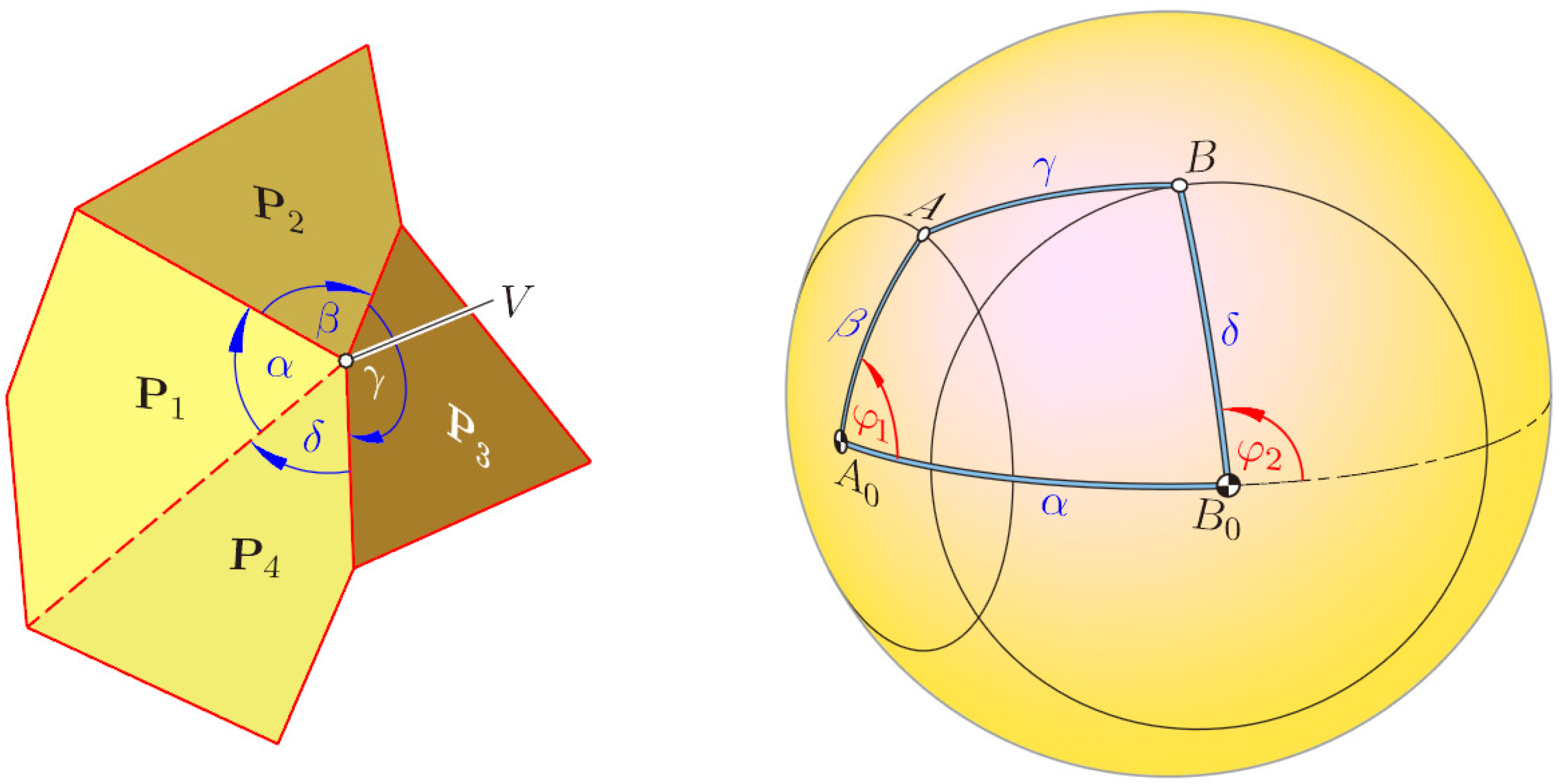
As a preparation, we provide a necessary condition for flexible polyhedral surfaces with two flat flexions. This condition refers to vertices V where four faces are meeting. Let α, β, γ and δ be the sequence of interior angles at V. Under the “vertex figure” of V, we understand the intersection of these four faces with a sphere, which is centered at V and whose radius is smaller than the shortest edge with endpoint V. Hence, the vertex figure is a spherical quadrangle with sides of lengths α, β, γ and δ (Figure 2). It has no effect on the flexions of this spherical quadrangle, when we replace any side of length λ by its complementary arc of length 2π − λ. Therefore, we can confine ourselves to the case α,…,δ < π; we call this quadrangle the reduced vertex figure.
Lemma 1. Let a flexible polyhedral surface be given that passes through two flat poses. Then, at each vertex, where four faces are meeting, the reduced vertex figure has either a plane of symmetry, at least after replacing one or two vertices by their antipodes, or the sides coincide in pairs.
Proof. The side lengths of the reduced vertex figure satisfy 0 < α,…,δ < π (see Figure 2). The spherical quadrangle admits two aligned poses if two of the following four equations hold:
- α+β+γ+δ=2π,
- α+β−γ−δ=0,
- α−β+γ−δ=0,
- α−β−γ+δ=0
Equations (a) and (b) are equivalent to β = π − α and δ = π − γ. When we replace A and B by their respective antipodes
and
, we obtain a spherical deltoid
. The same holds in the case where (a) and (d) are satisfied. Replacing one vertex by its antipode means replacing one edge of the pyramid with apex V by its reflection with respect to V (note the extensions
and
of P3 and P4 in Figure 6).
Equations (a) and (c) are equivalent to γ = π − α and δ = π − β. Then, the spherical quadrangle
is an isogram, i.e., a spherical quadrangle where opposite sides have the same length. Equations (b) and (c) lead to α = δ and β = γ, i.e., to a spherical deltoid, as well as Equations (c) and (d). Equations (b) and (d) give a spherical isogram.
Spherical kites have either an axis of symmetry or the flexion is trivial, since the sides coincide in pairs. Spherical isograms are either self-intersecting with an axis of symmetry or they have a center of symmetry. When in the latter case two neighboring vertices are replaced by their antipodes, then the axial symmetry of the spherical isogram is transformed into a planar symmetry. □
2. Miura-ori
Miura-ori is a Japanese folding technique named after Prof. Koryo Miura, The University of Tokyo. However, already before K. Miura, this technique was known; according to a personal communication with Gy. Darvas, it was kept as a military secret in Russia in the thirties of the last century. There are many applications of Miura-ori. It is, e.g., used for solar panels, because they can be packed in compact form and deployed into their flat shape by pulling on one corner only [4]. It serves as a kernel to stiffen sandwich structures. Furthermore, it can be utilized for the design of cupolas [1].
Let us analyze the process of folding a sheet of paper as depicted in Figure 3 with given valley and mountain folds, thus proving that this quadrangular surface is really continuously flexible. To begin with, we take two coplanar parallelograms with aligned upper and lower sides (Figure 4a).
Now, we rotate the parallelogram on the right-hand side against the left one about the common edge: the lower sides span a plane E1, and the upper sides span a plane E2 parallel to E1. We continue and extend the two parallelograms to a zig-zag strip by adding parallelograms, which are translatory congruent alternately to the left-hand or right-hand parallelogram of the initial pair. After this, the complete strip has its lower zig-zag boundary still placed in E1 and the upper one in E2 (see Figure 4c). This remains valid when we fix the plane E1, but vary the bending angle φ.
After iterated reflections in planes E2 parallel to E1 (Figure 4d) or after translations orthogonal to E1, the complete Miura-ori flexion is obtained as depicted in (Figure 5). When finally the two initial parallelograms become coplanar due to a bending angle of 180°, Miura-ori reaches a totally folded pose, which is again flat.
The set of edges of Miura-ori can be subdivided into two families of folds. The “horizontal” folds are copies of the zig-zag line in E1 and placed in horizontal planes. They are aligned in the stretched initial pose as depicted in Figure 3. The other folds are located in mutually parallel vertical planes, since their edges are obtained by iterated reflections in planes parallel to E1. We call these folds “vertical”. While the edges of each horizontal fold alternate between valley and mountain fold, all edges of a vertical fold are of the same type, either valley or mountain folds.
Now, we are going to analyze the self-motion of Miura-ori. For the sake of simplicity, we assume that all edges have a unit length (obviously, the side lengths of the zig-zag line in E1 can vary without restricting the flexibility; analogously, the distances between the planes through the horizontal folds need not be the same everywhere).
We fix the planes of one horizontal and one vertical fold, as well as the crossing point V of these two folds (Figure 6). Let P1,…, P4 be the four parallelograms meeting at V. We start with the motion of P1: the two edges of P1 with the common endpoint V rotate within the respective fixed planes, such that the included interior angle α < 90° remains constant (compare with Figure 4a). The reflection in the horizontal plane E2 maps P1 onto the second parallelogram P2. It has the same interior angle α at V and moves like P1.
Now, we elongate the horizontal edges of the other two parallelograms P3 and P4 (with interior angle 180°−α) beyond the fixed vertical plane by the unit length. This gives two additional parallelograms
and
with the interior angle α at V. Each shares a “vertical” edge with P1 or P2, respectively. Hence, the reflection in the fixed vertical plane must map P1 onto
and P2 onto
.
This reveals a hidden local symmetry of Miura-ori: when at each vertex V two adjacent parallelograms P3, P4 with congruent interior angles at V are replaced by their “horizontal elongations”
and
, respectively, we obtain a pyramid of four congruent parallelograms P1, P2,
,
with apex V. This pyramid flexes, such that it remains symmetrical with respect to the planes of the horizontal fold and the vertical fold passing through V (compare with Lemma 1).
Next, we study the relations between angles: we use a coordinate frame with origin V, with the x- and y-axis in the horizontal plane E2 and with the [yz]-plane spanned by the vertical fold passing through V (see Figure 6). Let 2φ and 2ψ be the bending angles between consecutive segments of the horizontal and vertical folds, respectively. Thus, the sides of P1 have the direction vectors:
and we obtain the dot product:
In the stretched position, the parallelogram P1 is located in the vertical [yz]-plane; the corresponding (half) bending angles are φ = 0° and ψ = 90° − α. The other limit is the totally folded position with P1 in the [xy]-plane, φ = α and ψ = 90°.
In order to obtain formulas for the dihedral bending angles 2γ and 2δ along edges of the horizontal and vertical folds (see Figure 6), we need the unit vector perpendicular to the plane of P1:
Its dot products with the unit vectors along the x- and z-axis give:
Theorem 2. During the self-motion of Miura-ori, the horizontal folds remain in mutually-parallel planes. The same holds for vertical folds, and their planes are orthogonal to the planes spanned by the horizontal folds. The dihedral bending angles 2γ along the edges of the horizontal folds are everywhere the same, as well as the angles 2γ for the vertical folds. They satisfy Equation (2), while φ and ψ are related by Equation (1).
The motion depicted in Figures 4 and 5 is not the only self-motion of Miura-ori. The initial pose admits bifurcations. Trivial flexions arise, e.g., when in the stretched position, we use any aligned horizontal fold as an axis of rotation for a folding. The same can be done, independently of each other, with several aligned horizontal folds. Furthermore, after full 180°-rotations, we obtain an n-fold covered strip and can treat it like a single strip. Hence, Miura-ori admits more than two flat poses.
Miura-ori is a very particular case of a Voss surface. This is a polyhedral surface with quadrangular faces, such that each 3 × 3 complex is a flexible Kokotsakis mesh [5] of the isogonal Type 3 (according to the enumeration given in [6]): at each vertex, opposite interior angles are either equal or complementary (Lemma 1); and there is an additional equation to satisfy ([7], p. 12). A long lasting open problem, the classification of flexible quadrangular Kokotsakis meshes [3] has recently been solved by I. Izmestiev [8]. The classification of flexible Kokotsakis meshes with a central n-gon and n ≥ 5 is still open.
3. Kokotsakis’ Flexible Tessellation
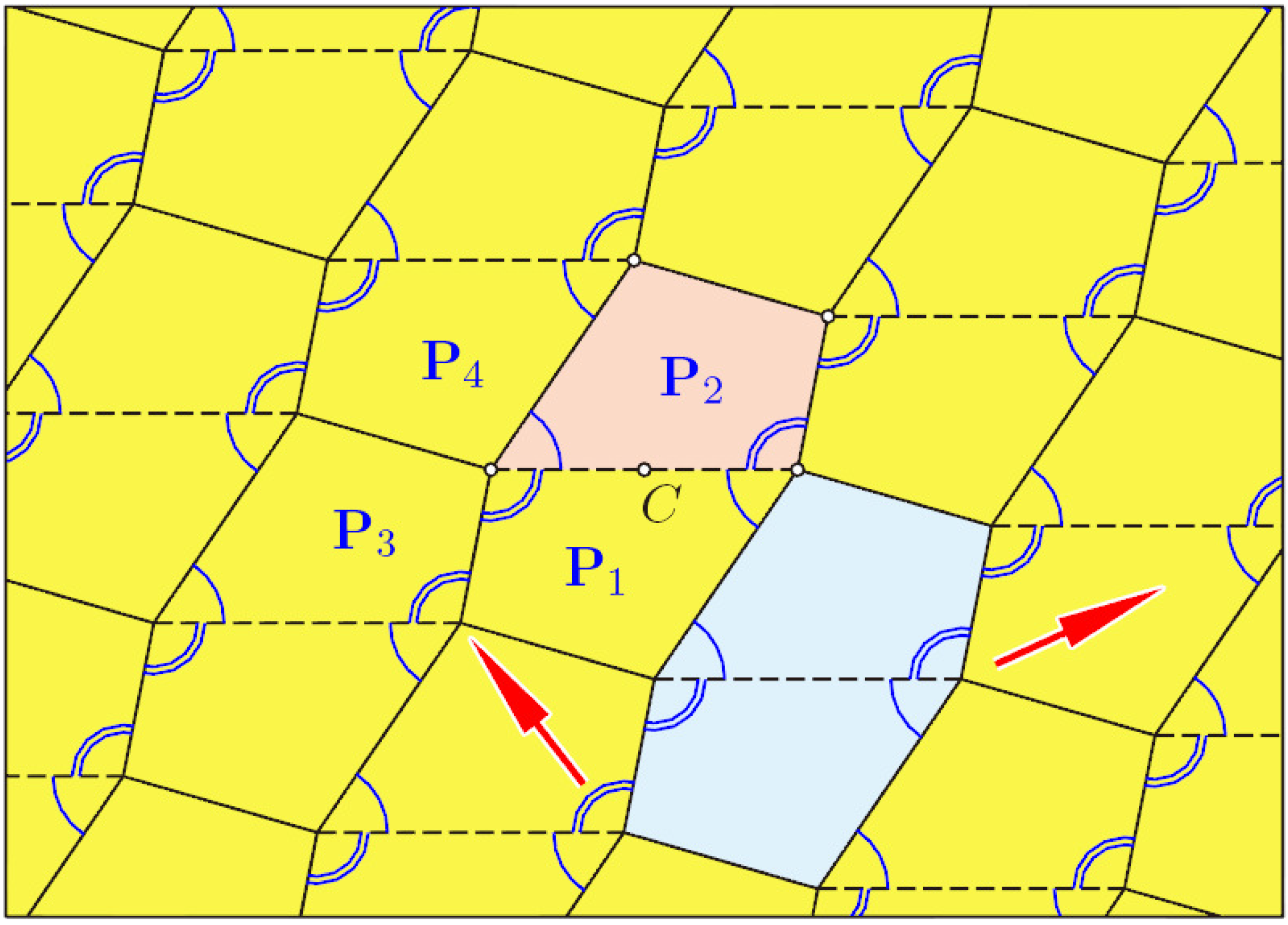
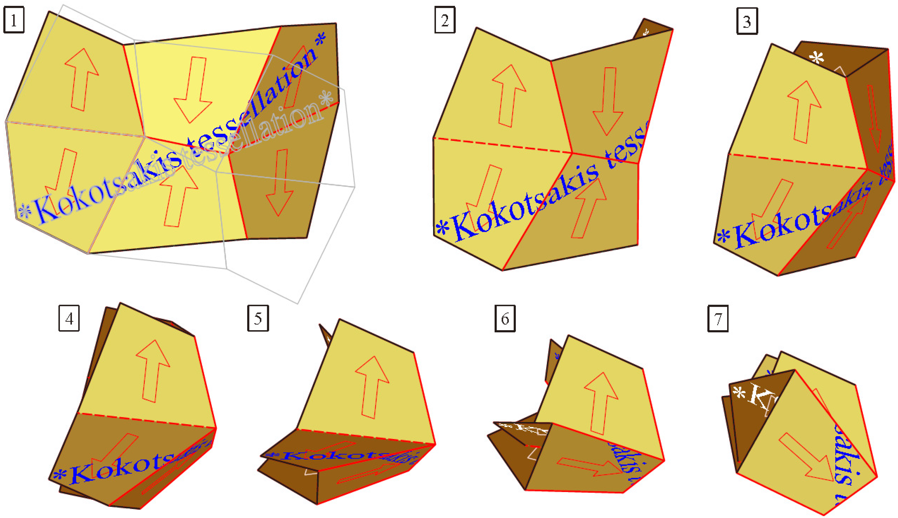
Another remarkable flexible mesh of quadrangles, which also starts from a flat initial pose, dates back to A. Kokotsakis. In [5] (p. 647), he proved the flexibility of the tessellation displayed in Figure 7. However, he did not present any geometric property of its spatial poses; this will be done below.
Choose an arbitrary quadrangle P1. By iterated rotations about the midpoints of the sides, we obtain a well-known regular tessellation of the plane (Figure 7). We can generate the same tessellation also in another way: when we glue together two adjacent quadrangles, we obtain a central-symmetric hexagon (blue shaded in Figure 7). Now, the same tessellation arises when this hexagon undergoes iterated translations, as indicated in Figure 7 by the red arrows.
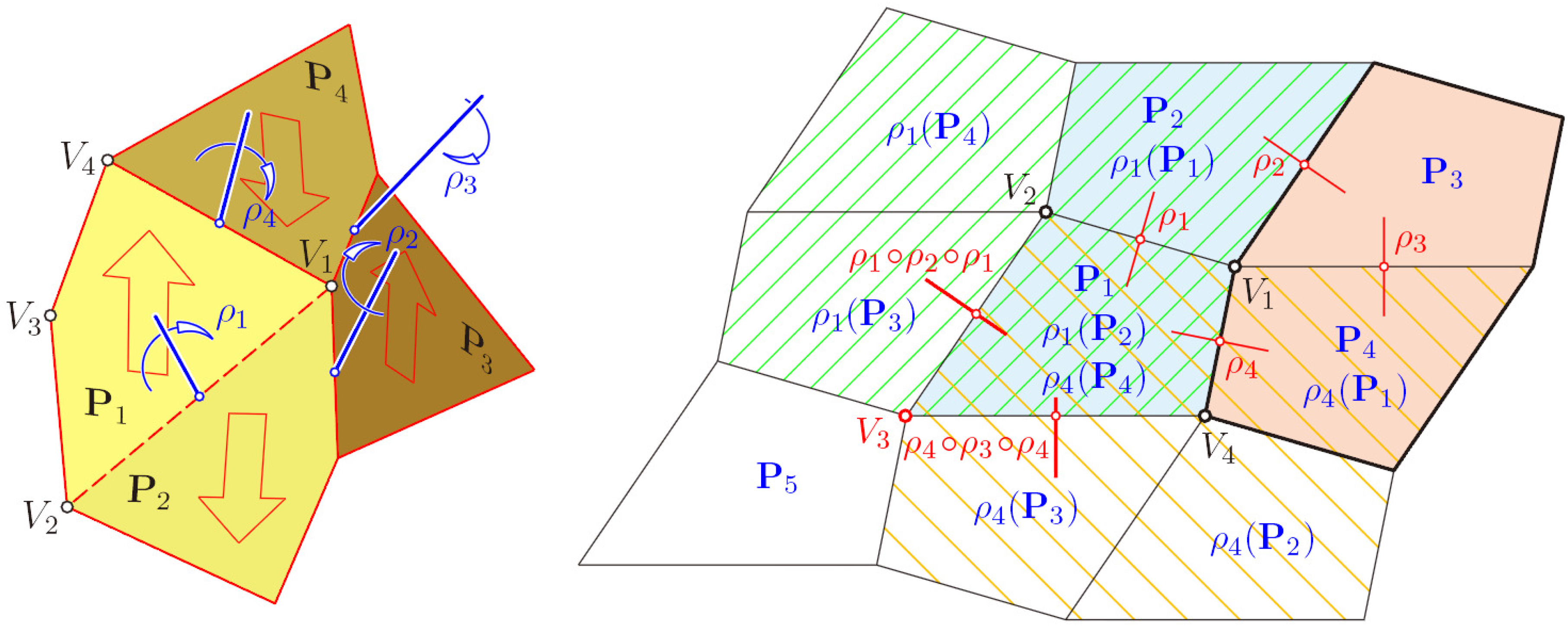
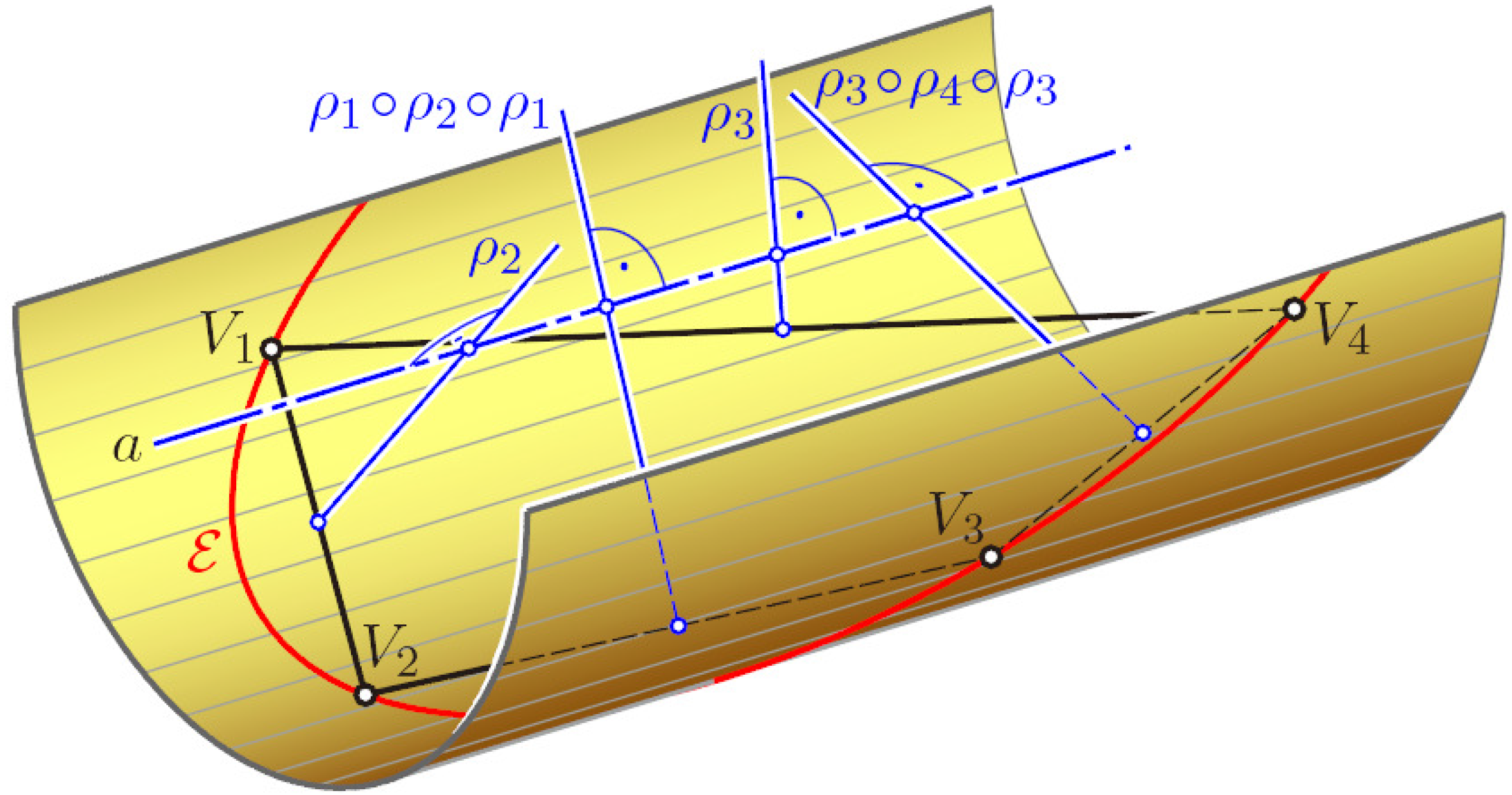
In the following, we prove for convex quadrangles that this polyhedral structure is flexible: let P1,…,P4 be four pairwise congruent faces with the common vertex V1 (shaded area in Figure 8). They form a four-sided pyramid with apex V1, and the four interior angles at V1 are respectively congruent to the four interior angles of a quadrangle. Our pyramid is flexible, provided the fundamental quadrangle is convex; otherwise, one interior angle at V1 would be greater than the sum of the other three interior angles, so that the only realization is flat.
According to the labeling in Figure 8, left, for any pair of adjacent faces, there is a respective 180°-rotation (“half-turn”) ρ1, ρ2, ρ3 or ρ4, which exchanges the two faces. Therefore, e.g., P2 = ρ1(P1). The axis of ρ1 is perpendicular to the common edge V1V2 and located in a plane that bisects the dihedral angle between P1 and P2.
After applying consecutively all four half-turns to the quadrangle P1, this is mapped via P2, P3 and P4 onto itself. This implies:
Now, we can extend this flexion of the pyramid step by step to the complete tessellation: the rotation ρ1 exchanges not only P1 with P2, but transforms the pyramid with apex V1 onto a congruent copy with apex V2 sharing two faces with its preimage. This is the area hatched in green in Figure 8, right. Analogously, ρ4 generates a pyramid with apex V4 sharing the faces P1 and P4 with the initial pyramid. Finally, there are two ways to generate a pyramid with apex V3. Either we transform ρ2 by ρ1 and apply ρ1 ○ ρ2 ○ ρ1, which exchanges V2 with V3, or we proceed with ρ4 ○ ρ3 ○ ρ4, which exchanges V4 with V3. Thus, we obtain two mappings, ρ1 ○ ρ2 and ρ4 ○ ρ3, with V1 ↦ V3, which are equal by virtue of Equation (3). Hence, each flexion of the initial pyramid with apex V1 is compatible with a flexion of the 3 × 3 complex of quadrangles. This can be extended to the complete tessellation (in [6], it is shown that this tessellation is a particular case of the line-symmetric Type 5 of flexible Kokotsakis meshes).
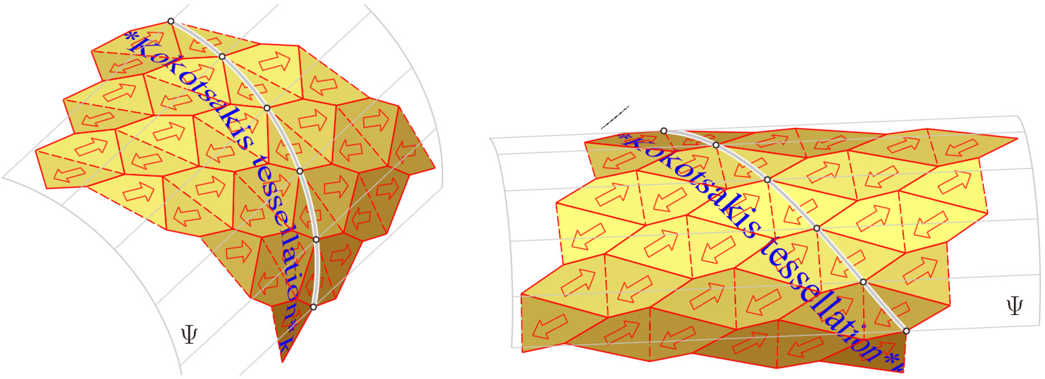
The product of two half-turns is a helical motion about the common perpendicular of the axes of the two half-turns. The angle of rotation and the length of translation is twice the angle and distance, respectively, between the two axes. When the pyramid with apex V1 is not flat, then the axes of the 180°-rotations ρ1,…,ρ4 are pairwise skewed; the common perpendicular of any two of them is unique. Equation (3) implies that the axes of the four rotations have a common perpendicular a. Hence, the motions ρ1 ○ ρ2 and ρ3 ○ ρ2 = ρ4 ○ ρ1 are helical motions with a common axis a. All vertices of the flexion have the same distance to a; they lie on a cylinder Ψ or revolution (in [11], T. Tarnai addresses another relation between planar tessellations and cylindrical shapes; he shows how semiregular tessellations can be folded into cylindrical shells).
When the quadrangles P3 and P4 are glued together, we obtain a line-symmetric skewed hexagon, one half of our initial pyramid with apex V1; the half-turn ρ3 maps this hexagon onto itself (Figure 8). We can generate the complete flexion by applying iterated helical motions ρ1 ○ ρ2 and ρ3 ○ ρ2 on this hexagon.
Theorem 3. Any flexion of the Kokotsakis tessellation is obtained from the line-symmetric hexagon consisting of the two planar quadrangles by applying the discrete group of coaxial helical motions generated by ρ1 ○ ρ2 and ρ3 ○ ρ2. In the initial flat pose, these generating motions are the translations applied to a centrally symmetric hexagon, thus generating the regular tessellation in the plane.
The flat initial pose of the pyramid with apex V1 admits a bifurcation between two continuous motions of the pyramid. Hence, the complete quad mesh admits two self-motions (Figure 9). When starting with a trapezoid P1 (compare with Figure 14 in [12]), one of these self-motions is trivial: it results from mutually-independent bending along aligned edges of the initial pose.
Once we have clarified that for each non-planar flexion, all vertices lie on a cylinder Ψ of revolution with axis a, we can give another explanation for the flexibility (see Figure 10): the plane spanned by the quadrangle V1…V4 intersects the circumcylinder Ψ along an ellipse E. Given a convex quadrangle V1…V4, there is a pencil of conics passing through the four vertices. This pencil includes an infinite set of ellipses, which is bounded by parabolas or pairs of parallel lines. Hence, we can specify an ellipse ε out of this pencil and choose one of the two right cylinders passing through ε.
Now, we define the half-turns ρ1 and ρ4; their axes pass through the midpoints of the sides V1V2 and V1V4, respectively, and intersect the cylinder’s axis a perpendicularly (see Figure 10). The common normal of the lines V2V3 and a is the axis of ρ1○ρ2○ρ1; that between V3V4 and a is the axis of ρ4○ρ3○ρ4. Iterations of these half-turns transform our initial face P1 into all faces of the flexion.
In [12], cases are studied where a particular flexion of a m × n-complex closes. This gives rise to an infinitesimally rigid tessellation on a right cylinder by plane quadrangles (see Figure 11).
Theorem 4. When the basic quadrangle of the flexible Kokotsakis’ tessellation is cyclic, i.e., has a circumcircle, it admits a second flat pose: all quadrangles are packed into a single circumcircle. However, this fails for real-world models, because of self-intersections.
Proof. In the case of a cyclic quadrangle, the pencil of circumscribed conics includes one circle. There is a unique right cylinder passing through this circle, and the corresponding axes of half-turns ρ1,…,ρ4 are coplanar. The complete flexion is flat; the circumcircles of all faces coincide (compare with Figure 12). Similar to Miura-ori, this tessellation mesh can be “packed” into a very small size, such that it finds a place in the circumcircle of one quadrangle, at least “theoretically”, i.e., without paying attention to self-intersections. However, a real-world model consisting of at least 3 × 3 quadrangles cannot approach such a pose, since the faces have to be placed one upon the other. Then, there is a collision between the “edges” spanning over distant levels and the vertices of quadrangles placed between them. □
In the case of a cyclic quadrangle, opposite angles are complementary. Therefore, this flexible tessellation is an example of a Voss surface, too.
4. Bricards’ Octahedra of Type 3
In this final section, an octahedron is understood as a double-pyramid over a quadrangle, which need not be planar. Hence, the octahedron contains three pairs (A, A′), (B, B′) and (C, C′) of opposite vertices. Each of them can be seen as a pair of apices of a double pyramid; the corresponding bases, called “equators”, are the quadrangles BCB′C′, ACA′C′ or ABA′B′, respectively.
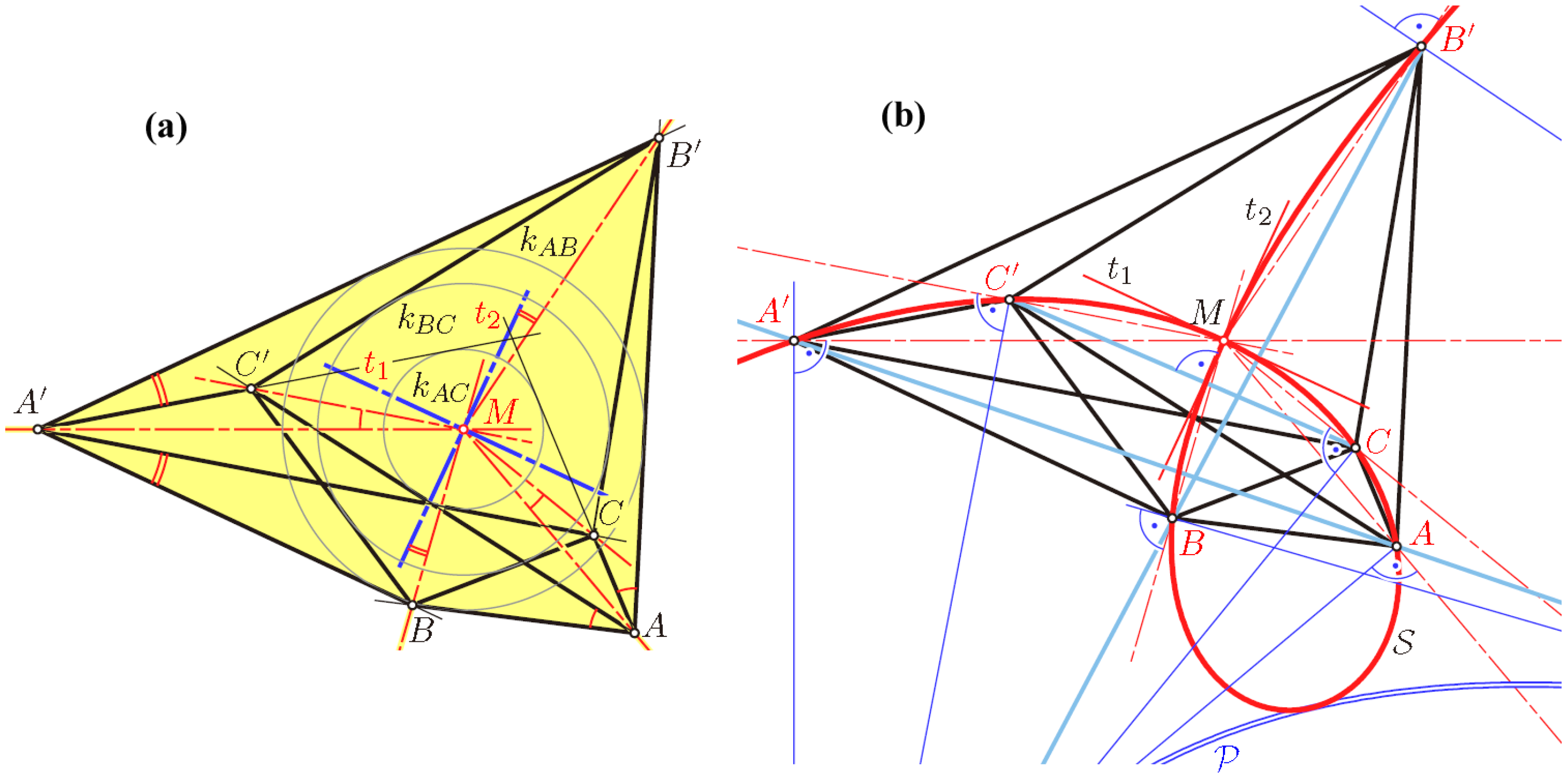
According to R. Bricard’s fundamental result [13], there are three types of flexible octahedra. Those without any symmetry belong to Type 3 and admit two flat poses. They can be defined as shown in Figure 13a.
Each of the three equators is a quadrangle with sides tangent to a circle with the same center M. Hence, there is a local symmetry at each vertex with respect to an axis, which passes through M (note Lemma 1).
The following theorem relates the given flat pose to a strophoid S, which is defined as a circular curve of degree three with a node N and orthogonal tangents at the node. On S, a symmetric relation can be defined [14]: two points P, P′ of S \ {N} are called associated if the lines NP and NP′ are symmetric with respect to the node tangents t1 and t2. Furthermore, the strophoid S is the locus of points X with the property that one angle bisector of the lines XP and XP′ passes through the node N. This holds simultaneously for all pairs (P, P′) of associated points of S.
As a consequence, at our given flat pose of the octahedron, there must be a strophoid S with the node N = M and associated points (A, A′), such that S passes also through B, B′, C and C′ (Figure 13b).
Theorem 5. For any strophoid S, each triple of associated pairs of points (A, A′), (B, B′) and (C, C′) defines a flat pose of a flexible octahedron. This octahedron has a second flat pose.
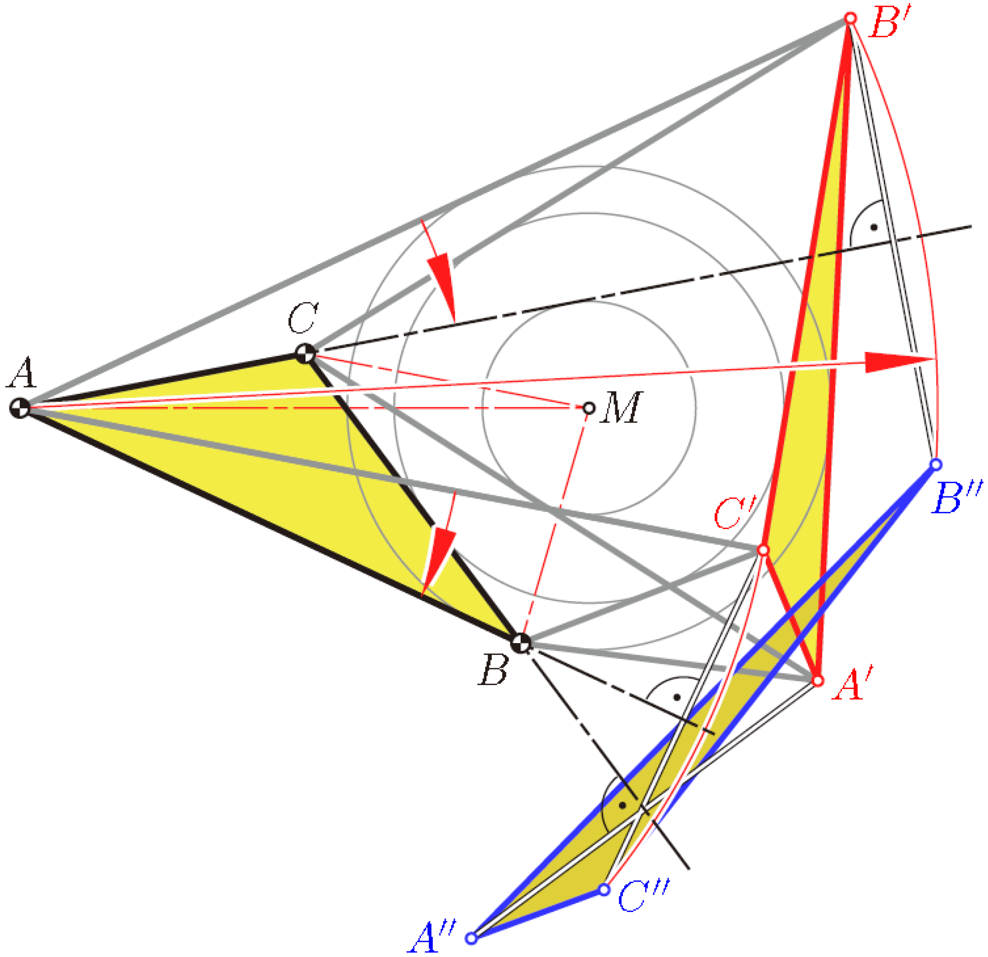
Proof. In order to obtain the second flat pose, let us keep the face ABC fixed, while the opposite triangle A′B′C′ is replaced by a congruent copy A″B″C″. Both flat poses must show respectively equal distances AB′ = AB″, AC′ = AC″,…, CB′ = CB″. We show that the reflection in the line AB maps C′ onto C″, the reflection in the line AC maps B′ onto B″ and the reflection in the line BC maps A′ onto A″ (see Figure 14). Firstly, these reflections preserve the distances to the points of the fixed triangle. Secondly, since both pairs of lines, (AB, AB′) and (AC, AC′), are symmetric with respect to AM, the angles ∢B′AB″ = 2 ∢B′AC and ∢C′AC″ = 2 ∢C′AB are equal. Hence, there is a rotation about A, which sends the side B′C′ onto B″C″ and preserves the length. The same holds for the other sides A′B′ and A′C′. □
Furthermore, at spatial poses of the flexible octahedron of Type 3, there is a local symmetry at each vertex V (Lemma 1): the six planes of symmetry share a common axis a (see, e.g., [15], Figure 3). All equators are placed on one-sheet hyperboloids of revolution with the axis a. As demonstrated in [16,17], even at each spatial pose, there is a particular spatial cubic passing through the six vertices. Of course, this cubic is the spatial analogue of the strophoid S displayed in Figure 13b.
All flexible octahedra have self-intersections. Real-world models work only when either they are built as a framework or one pair of opposite faces is removed (see, e.g., [7], Figure 5).
There exist also particular flexible octahedra of Type 2, i.e., with an axis of symmetry, which admit two flat poses. They are a sort of limiting case when point M in Figure 13a, tends to infinity (see, e.g., [15], Figure 4). G. Nawratil [18] proved that there is one non-trivial type of a flexible octahedron with some vertices at infinity: it consists of two prisms with a kite as the common basis; the generators of the prisms are orthogonal to the kite’s axis of symmetry. These examples can even be free of self-intersections.
The analogue of Type 3 in the hyperbolic space is also flexible. Of course, more sub-types can be distinguished, since the vertices can be either finite points or on the absolute conic or outside (note [19]). Recently, A.A. Gaifullin generalized all of this in [20]: He proved that, in the algebraic sense, Type 3 is the simplest; there exist flexible higher-dimensional analogues, so-called cross-polytopes, in all dimensions, in Euclidean spaces, as well as in spherical and hyperbolic spaces.
5. Conclusions
This paper focuses on three well-known examples of continuously-flexible polyhedral surfaces and analyzes the geometry behind them. Emphasis is placed on versions with two flat poses. The examples, which are studied in detail, are Miura-ori, A. Kokotsakis’ flexible tessellation with congruent convex quadrangles and R. Bricard’s Type-3 octahedra. We do not claim that the presented three examples are the only ones with two flat poses.
Conflicts of Interest
The author declares no conflict of interest.
References and Notes
- Barej, M.; Hoffmann, S.; Knief, Ch.; Trautz, M.; Corves, B. Design and Application Studies for a Cupola Forming Orbital Arrangment of Miura-Ori Basic Units. J. Geom. Graph. 2015, 19. in press. [Google Scholar]
- Wunderlich, W.; Schwabe, C. Eine Familie von geschlossenen gleichflächigen Polyedern, die fast beweglich sind. Elem. Math. 1986, 41, 88–98. [Google Scholar]
- A Kokotsakis mesh is a polyhedral structure consisting of an n-sided central polygon P0, n ≥ 3, which is surrounded by a belt of other polygons; at each vertex of P0 four faces are meeting [5]. In the case n = 4 the mesh is called quadrangular. The triangular case (n = 3) is equivalent to an octahedron.
- Miura, K. Method of Packaging and Deployment of Large Membranes in Space; Report No. 618; The Institute of Space and Astronautical Science: Tokyo, Japan, 1985. [Google Scholar]
- Kokotsakis, A. Über bewegliche Polyeder. Math. Ann. 1932, 107, 627–647. [Google Scholar]
- Stachel, H. A kinematic approach to Kokotsakis meshes. Comput. Aided Geom. Des. 2010, 27, 428–437. [Google Scholar]
- Stachel, H. On the flexibility and symmetry of overconstrained mechanisms. Philos. Trans. A Math. Phys. Eng. Sci 2013, 372. [Google Scholar] [CrossRef]
- Izmestiev, I. Classification of Flexible Kokotsakis Polyhedra with Quadrangular Base; Cornell University Library: Ithaca, NY, USA, 2014; p. 76. [Google Scholar]
- Tachi, T. Freeform Variations of Origami. J. Geom. Graph 2010, 14, 203–215. [Google Scholar]
- Tachi, T. Generalization of Rigid Foldable Quadrilateral Mesh Origami. J. IASS 2009, 50, 173–179. [Google Scholar]
- Tarnai, T. Folding of Uniform Plane Tessellations. 2nd International Meeting of Origami Science and Scientific Origami, Otsu/Shiga, Japan, 29 November–2 December 1994; pp. 83–91.
- Stachel, H. A Flexible Planar Tessellation with a Flexion Tiling a Cylinder of Revolution. J. Geom. Graph 2012, 16, 153–170. [Google Scholar]
- Bricard, R. Mémoire sur la théorie de l’octaèdre articulé. J. Math. Pur. Appl. Liouville 1897, 3, 113–148, In French. [Google Scholar]
- Abu-Saymeh, S.; Hajja, M.; Stachel, H. Equicevian Points and Cubics of a Triangle. J. Geom. Graph 2014, 18, 133–157. [Google Scholar]
- Stachel, H. Zur Einzigkeit der Bricardschen Oktaeder. J. Geom. 1987, 28, 41–56. [Google Scholar]
- Bricard, R. Leçons de Cinématique; Gauthier-Villars: Paris, France, 1926. Tome I. (In French) [Google Scholar]
- Bricard, R. Leçons de Cinématique; Gauthier-Villars: Paris, France, 1927. Tome II. (In French) [Google Scholar]
- Nawratil, G. Flexible octahedra in the projective extension of the Euclidean 3-space. J. Geom. Graph 2010, 14, 147–169. [Google Scholar]
- Slutskiy, D. A necessary flexibility condition of a nondegenerate suspension in Lobachevsky 3-space. Russ. Acad. Sci. Sb. Math 2012. [Google Scholar] [CrossRef]
- Gaifullin, A.A. Flexible Cross-Polytopes in Spaces of Constant Curvature. Proc. Steklov Inst. Math 2014, 286, 77–113. [Google Scholar]
Figure 1.
This polyhedron called “Vierhorn” is locally rigid, but snaps between its spatial pose (b) and the two flat realizations (a,c). Dashes in the unfolding (d) indicate valley folds.
Figure 1.
This polyhedron called “Vierhorn” is locally rigid, but snaps between its spatial pose (b) and the two flat realizations (a,c). Dashes in the unfolding (d) indicate valley folds.
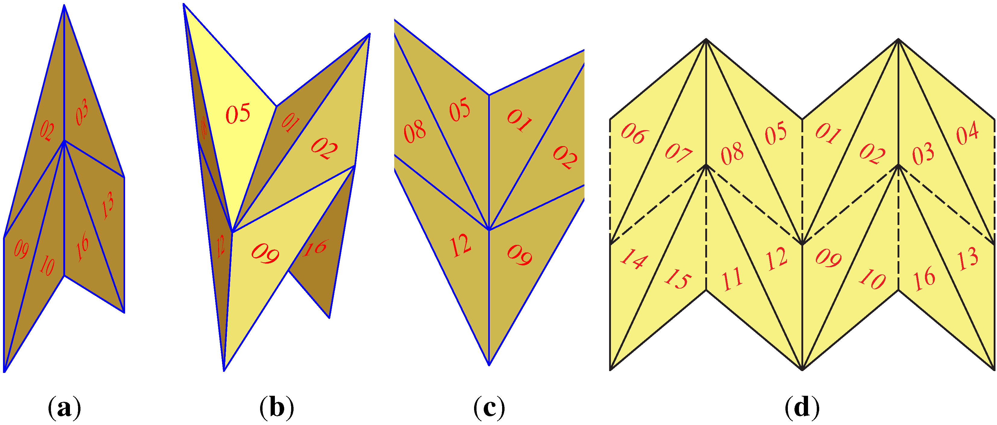
Figure 2.
The interior angles at the vertex V serve as side lengths of the spherical four-bar A0ABB0, which controls the dihedral angles φ1 and φ2 during the flexion.
Figure 2.
The interior angles at the vertex V serve as side lengths of the spherical four-bar A0ABB0, which controls the dihedral angles φ1 and φ2 during the flexion.

Figure 3.
Miura-ori unfolded; dashes are valley folds; full lines are mountain folds.
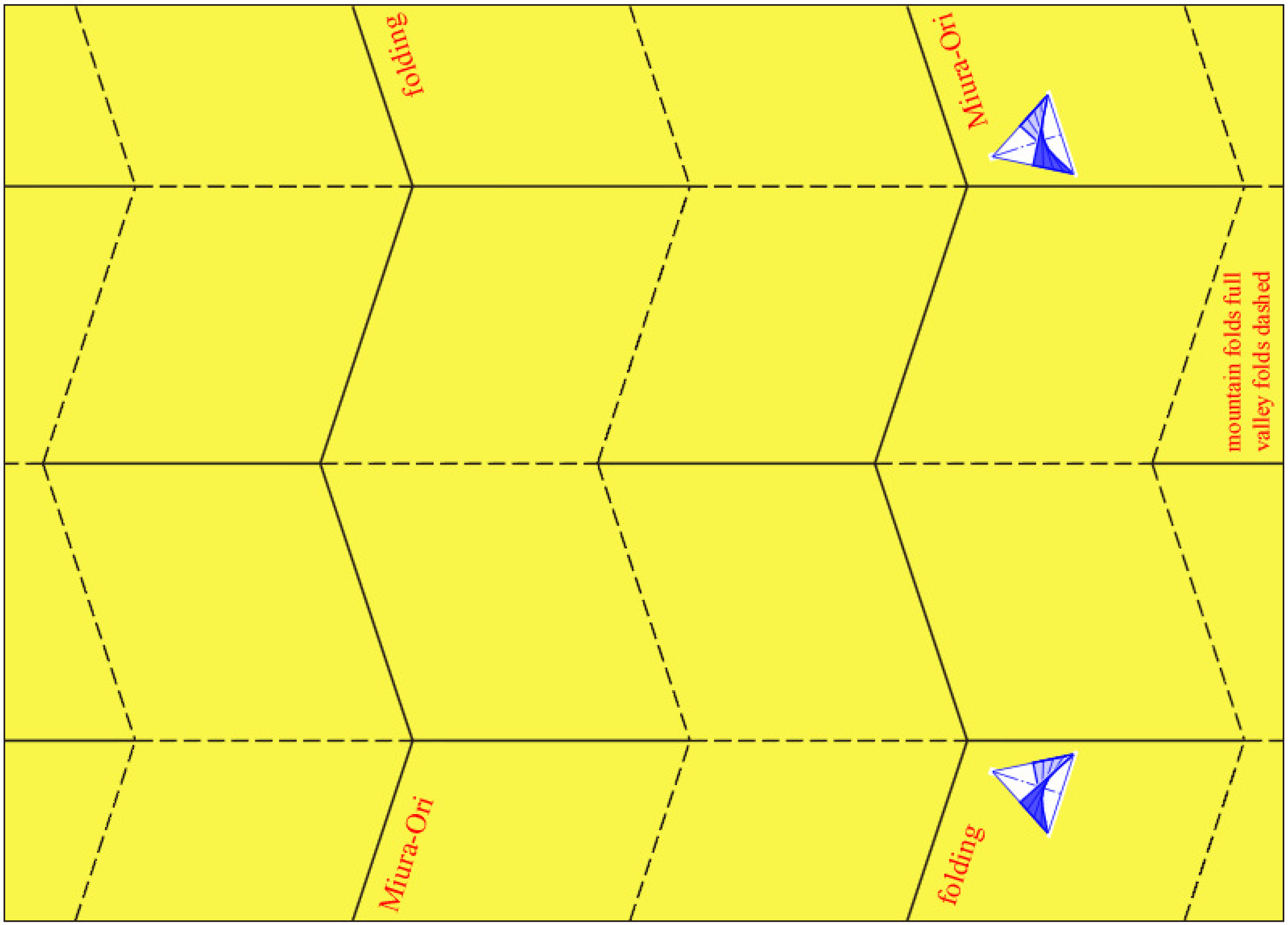
Figure 4.
Generating neighboring zig-zag strips of Miura-ori.
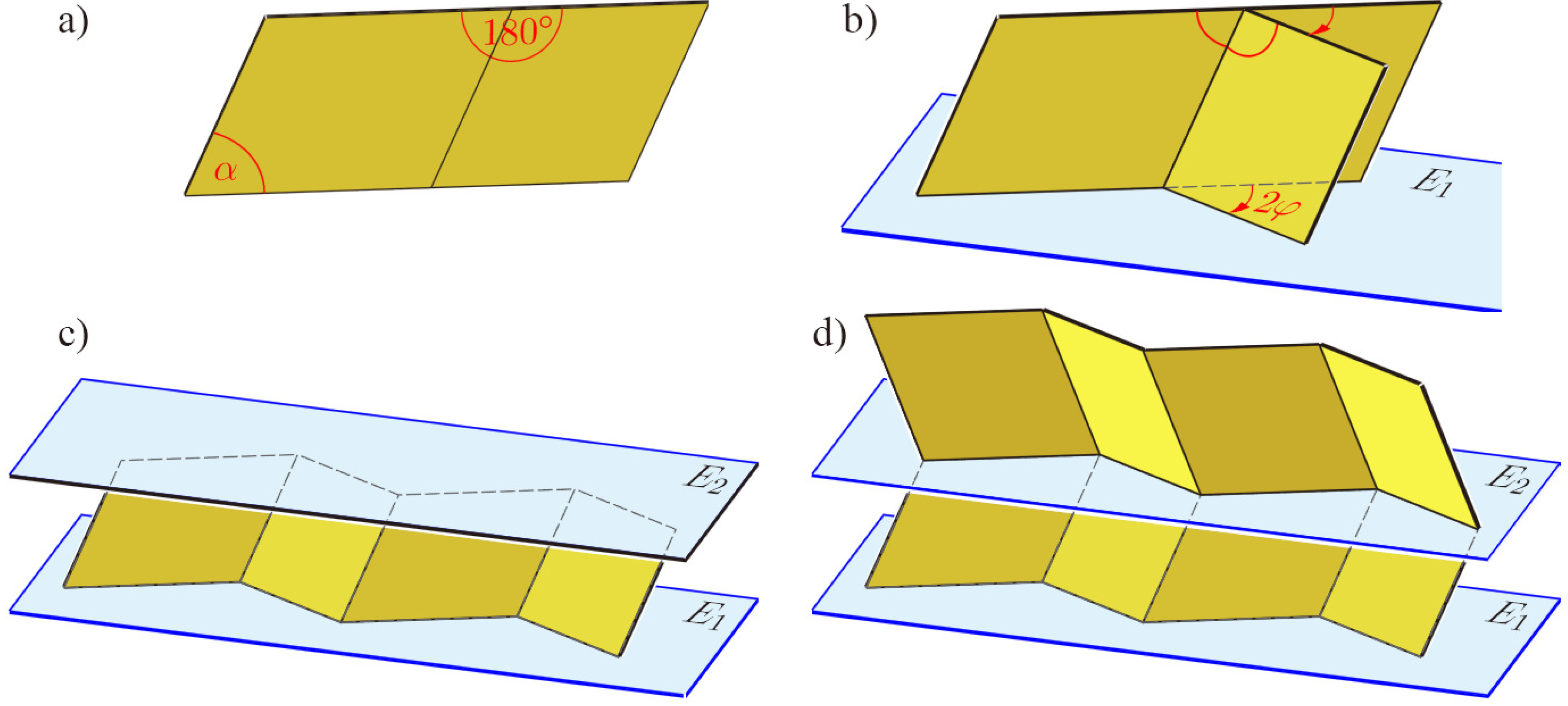
Figure 5.
Snapshots of the folding procedure of Miura-ori.
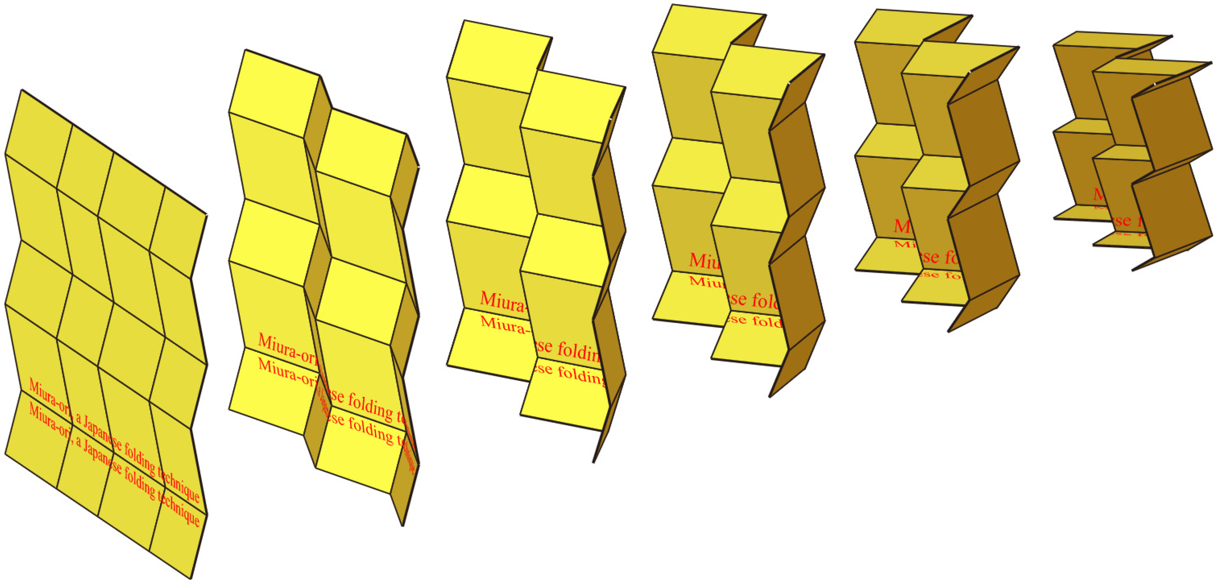
Figure 6.
The two-fold local symmetry at each vertex V becomes visible when the edge between P3 and P4 is extended beyond V.
Figure 6.
The two-fold local symmetry at each vertex V becomes visible when the edge between P3 and P4 is extended beyond V.
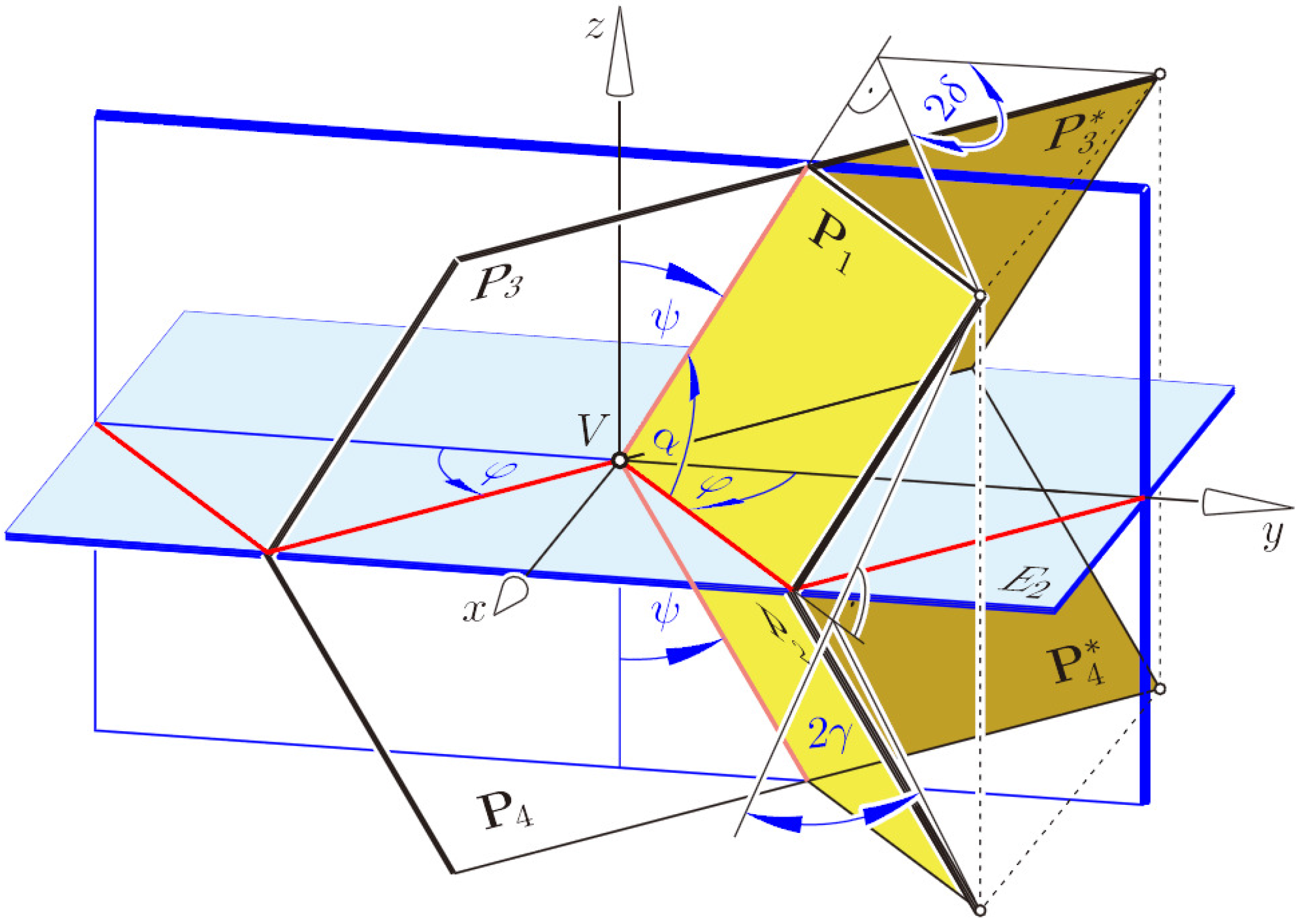
Figure 7.
Kokotsakis’ flexible mesh unfolded.

Figure 8.
The flexion of a four-sided pyramid can be extended to a flexion of the complete tessellation.
Figure 8.
The flexion of a four-sided pyramid can be extended to a flexion of the complete tessellation.

Figure 9.
The Kokotsakis tessellation admits two self-motions.

Figure 10.
There is an infinite set of ellipses passing through the vertices of a convex quadrangle.
Figure 10.
There is an infinite set of ellipses passing through the vertices of a convex quadrangle.

Figure 11.
This is an infinitesimally rigid pose of a flexible tessellation mesh [12].
Figure 11.
This is an infinitesimally rigid pose of a flexible tessellation mesh [12].
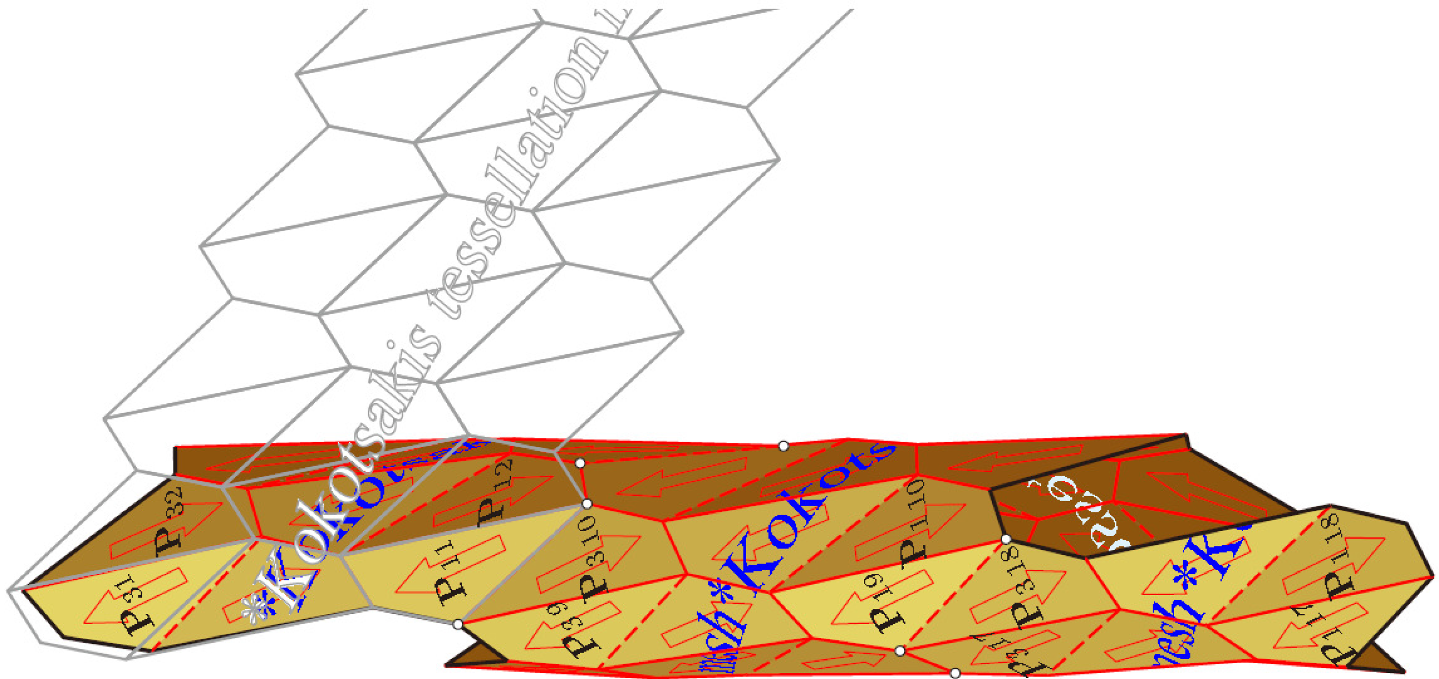
Figure 12.
The tessellation mesh of a cyclic quadrangle admits a second flat pose.

Figure 13.
In the flat pose, the pairs of opposite points of Bricard’s Type-3 flexible octahedron are associated with a strophoid S.
Figure 13.
In the flat pose, the pairs of opposite points of Bricard’s Type-3 flexible octahedron are associated with a strophoid S.

Figure 14.
The two flat poses of a Type-3 flexible octahedron.

© 2015 by the authors; licensee MDPI, Basel, Switzerland This article is an open access article distributed under the terms and conditions of the Creative Commons Attribution license (http://creativecommons.org/licenses/by/4.0/).
Share and Cite
MDPI and ACS Style
Stachel, H. Flexible Polyhedral Surfaces with Two Flat Poses. Symmetry 2015, 7, 774-787. https://doi.org/10.3390/sym7020774
AMA Style
Stachel H. Flexible Polyhedral Surfaces with Two Flat Poses. Symmetry. 2015; 7(2):774-787. https://doi.org/10.3390/sym7020774
Chicago/Turabian StyleStachel, Hellmuth. 2015. "Flexible Polyhedral Surfaces with Two Flat Poses" Symmetry 7, no. 2: 774-787. https://doi.org/10.3390/sym7020774