
Collaborative CAD Synchronization Based on a Symmetric and Consistent Modeling Procedure


1
School of Computer, Wuhan University, Wuhan 430072, China
2
State Key Laboratory of Digital Manufacturing Equipment and Technology, Huazhong University of Science and Technology, Wuhan 430074, China
3
Division of Ocean Engineering, Korea Advanced Institute of Science and Technology, Daejeon 34141, Korea
*
Author to whom correspondence should be addressed.
Symmetry 2017, 9(4), 59; https://doi.org/10.3390/sym9040059
Submission received: 4 March 2017
/
Revised: 11 April 2017
/
Accepted: 18 April 2017
/
Published: 23 April 2017
Abstract
:One basic issue with collaborative computer aided design (Co-CAD) is how to maintain valid and consistent modeling results across all design sites. Moreover, modeling history is important in parametric CAD modeling. Therefore, different from a typical co-editing approach, this paper proposes a novel method for Co-CAD synchronization, in which all Co-CAD sites maintain symmetric and consistent operating procedures. Consequently, the consistency of both modeling results and history can be achieved. In order to generate a valid, unique, and symmetric queue among collaborative sites, a set of correlated mechanisms is presented in this paper. Firstly, the causal relationship of operations is maintained. Secondly, the operation queue is reconstructed for partial concurrency operation, and the concurrent operation can be retrieved. Thirdly, a symmetric, concurrent operation control strategy is proposed to determine the order of operations and resolve possible conflicts. Compared with existing Co-CAD consistency methods, the proposed method is convenient and flexible in supporting collaborative design. The experiment performed based on the collaborative modeling procedure demonstrates the correctness and applicability of this work.
1. Introduction
Given the rapid development of economic globalization, collaborative design, collaborative product development, and cloud manufacturing have become unavoidable strategic means of competition [1,2,3]. In this way, product design work is done by different enterprises or departments in different locations. Computer-supported cooperative work (CSCW) is a common task for a collaborative work group in a computer-supported network environment and originated in the 1980s [4]. The technology and advantages of CSCW create more competitiveness in industrial manufacturing. Specifically, in collaborative design the computer aided design (CAD) technology has been combined with CSCW and the concept of collaborative CAD (Co-CAD) emerges [5,6,7,8,9].
Typical studies of Co-CAD systems of replicated architecture assume that the execution orders are different among the cooperative sites and then try to maintain a consistent result after the operations are received and executed on different sites with divergent orders [10,11,12]. This assumption comes from co-editing systems of replicated architecture, in which a lot of tricky algorithms are proposed to address the challenge of how to achieve consistent results in a non-consistent (dis-ordered) operations sequence. This challenge makes sense in co-editing systems where both the text data structure and text operations semantics are simple.
However, in Co-CAD systems, the data structure and operations semantics are much more complicated than in co-editing systems. The disordered operations sequence will result in many complex problems, such as collaborative name matching or feature conflict [13,14,15,16,17,18]. Therefore, the Co-CAD system is more complicated than a co-editing system and so it is difficult to achieve consistent results with a non-consistent 3D modeling operation sequence [19].
Furthermore, even if consistent (geometric) results are achieved with divergent modeling histories, a new problem comes into being. Modern CAD systems are history-based and the modeling history represents the design intent [20,21]. Divergent modeling histories with the same geometric result are not valid for a given design intent. Unfortunately, this problem is generally neglected by almost all previous studies of Co-CAD.
This paper proposed a novel synchronization method for Co-CAD to avoid the above problems. By this method, operations are first organized according to their causal relationship. Then the concurrent operations are retrieved. A symmetric concurrency control mechanism is proposed to form a unique operation sequence. While preserving the design intent of all sites as much as possible, an operation that would cause conflict is determined and withdrawn during the procedure. Then a symmetric and consistent modeling operation procedure is generated in all sites to achieve a unique and valid modeling result. Meanwhile, the modeling history in each site remains consistent. The rest of the paper is organized as follows: in Section 2, some related work of collaborative design is reviewed. In Section 3, some related concepts and definitions are presented and then the overall methodology of the paper is proposed. In Section 4, the technical details of the proposed symmetric synchronization model for Co-CAD are introduced. In Section 5, a collaborative design process is presented as a case study to demonstrate the method of this paper and Section 6 gives the conclusions of this paper.
2. Related Work
In an ideal collaborative design environment, co-designers from different design sites could accomplish the design task in a sharing workspace. The Co-CAD system should offer tools and technical support for mutual awareness, collaboration, and interaction in the collaborative design environment [22,23,24].
Early Co-CAD architecture is centralized. All modeling operations must be transmitted to the server execution, which hinders a quick local response. Compared with the Co-CAD system with centralized architecture, the one based on replicated architecture is better for the effective local response [25]. At present, research into Co-CAD mainly focuses on replicated concurrency control methods.
A typical type of Co-CAD solution is authority-based methods. The basic idea is that each site acquires the operation privilege by a certain rule so all the operations can be executed sequentially. Dietrich [26] designed a strict concurrency control system that uses the “floor control” mechanism. Only when a site has a token can it execute the corresponding modeling operation, while other sites cannot execute modeling operations on the shared model but only by observing the basic state of the model. Stork et al. [27,28] used an optimistic object locking mechanism and common rules and protocols to achieve concurrency control, thereby achieving consistency of results. Li developed a cooperative design system based on neutral modeling commands that adopts a feature granularity locking mechanism to realize concurrency control and maintain consistency [29,30]. This method reduces the granularity of the lock mechanism to the feature level. The Replicated Collaborative CAD System (RCCS) system used a local locking mechanism to achieve concurrency control [15]. Yang used a fine granular locking mechanism for a replicated collaboration system [31]. The analysis shows that, with the authority-based mechanism, only one user is allowed to edit the sharing model at a time, which does not meet the demands of free multi-user concurrent design well.
An important and successful application of CSCW is a collaborative editing system for text documents. In the co-editing system, operation transformation (OT) is an effective idea that attempts to adjust the editing parameters of disordered editing operations for a consistent editing result among co-editing sites. Based on this thought, a lot of OT algorithms are proposed [32,33,34,35,36,37,38,39,40]. Inspired by co-editing, OT algorithms are used in 3D collaborative design. Liu proposed a 3D semantic-based OT method to support less constrained multi-user interaction and achieve consistency in Co-CAD systems [41]. However, adopting OT for 3D models requires complicated model geometry computation and involves complex topological naming issues.
In Co-CAD, concurrent operation may cause operation conflicts or divergent modeling results by operation interactions. Therefore, many studies focus on conflict detection and solutions [42,43,44,45,46]. Yu [47] proposed a collaborative design framework using the X3D operation models for conflict detection and resolution. Cheng [19] extended commutative replicated data type (CRDT) capability to meta operation conflict resolution from 1D to 3D applications. Cai [48] developed a homogeneous CAD online integrated system. The relationships between collaborative CAD modeling operations are divided into commutative and non-commutative. Concurrency control and result consistency maintenance are realized.
Due to the current mainstream CAD system having adopted the historical parametric feature modeling technology, modeling history information is useful and important for Co-CAD, such as for reverse engineering design analysis or as important modeling knowledge sharing [49]. The existing Co-CAD solutions lack the consideration of modeling history consistency. Divergent modeling history in each collaborative site would recede the significance of modeling history. Moreover, traditional Co-CAD consistency methods have the disadvantages of inflexible interaction or problems with geometric computation and collaborative naming. These shortcomings impede the widespread adoption and acceptance of Co-CAD. Therefore, this paper aims at not only a convenient and valid solution for the consistent modeling result in Co-CAD, but also the maintenance of modeling history consistency.
3. Overall Methodology and Related Concepts
The most basic goal of Co-CAD is to get consistent results through collaborative design operations from all collaborative sites, which is similar to co-editing. In Co-CAD, the co-operation objects are shaped 3D models, different from characters in co-editing. Hence, it is not possible to apply collaboration consistency maintenance methods directly. Before proposing the Co-CAD synchronization methodology, some related definitions and concepts in Co-CAD process are presented.
3.1. Preliminaries
3.1.1. Related Definitions in Co-CAD Modeling
According to Lamport’s “happened-before” theoretical basis [50], this paper presents the following set of definitions used in collaborative CAD processes, including features, state vectors, modeling operations, result models, causality, concurrency, and partial concurrency.
Definition 1. Features.
The generalized conception of features is a geometrical entity that is meaningful to design or manufacturing activities. The narrow concept of features is the basic modeling operations provided by mainstream commercial CAD systems to reflect specific engineering semantics, such as convex, shell, fillet, and so on.
Definition 2. The state vector.
A state vector SV [51] is saved on each collaboration site. It is an n-dimensional vector, where n is the number of collaborative sites. The state vector of site j is denoted as SVj[i], i ∈ {1, 2,…, n − 1}, which records the number of operations that the site j has executed from the site i. The state vector of the operation O issued by site j is recorded as SVO[k], k ∈ {1, 2,…, n − 1}, which records the number of operations from site k that have been executed on site j when O is executed on site j.
Definition 3. Modeling operations.
Collaborative CAD modeling operations O can be defined as <S, SV, Feature(O), T(O)>. S is the site that generates the modeling operation O. SV is the state vector of modeling operation O when being executed on site S. Feature(O) is the feature of modeling operation O on site S. T(O) is the type of modeling operations, including creation, modification, and deletion, denoted as T(O) ∈ {CREATION, MODIFICATION, DELETION}.
Definition 4. Result model.
Geometric result of a feature model after executing one or more modeling operations. Design history is stored in the feature model, and expressed as operation sequence. Each operation sequence corresponds to a final geometric result, and the final geometric result is represented by the boundary model.
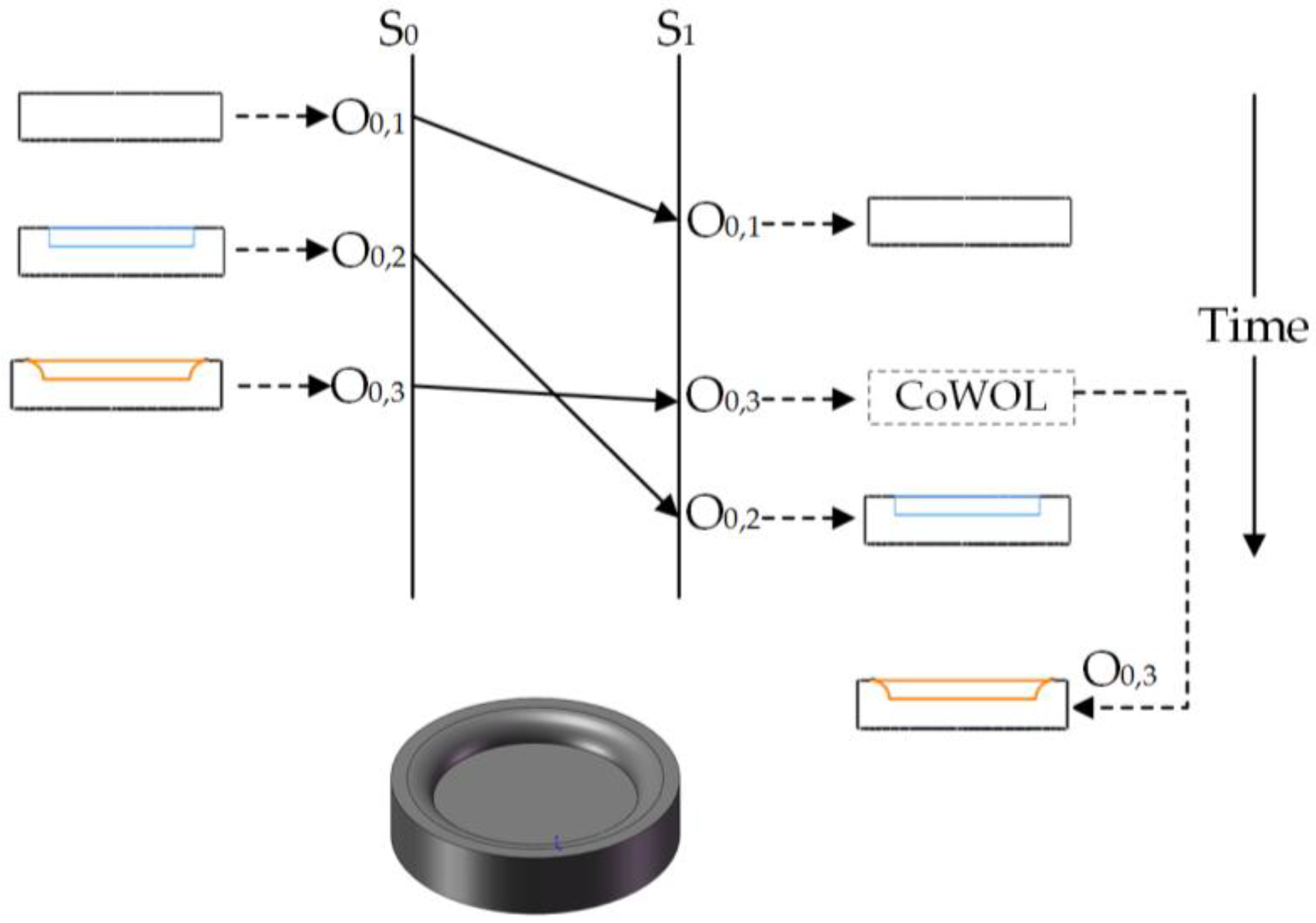
Definition 5. Causality relationship.
Suppose there is an arbitrary pair of modeling operations Oa and Ob sent by site Si and Sj and there are three conditions: (1) Si and Sj are the same site, and Oa is generated before Ob; (2) Si and Sj are different sites, and Oa is generated before Ob in site Si; (3) there is an operation Ox, Oa→Ox and Ox→Ob. If and only if Oa and Ob satisfy any one condition above, there is a causal relationship between Oa and Ob (denoted as Oa→Ob).
In Figure 1, Operation O0,2 and O0,3 are sent by the same site S0. O0,2 creates an extruded cut on the boss created by O0,1, denoted as Feature(O0,2). O0,3 creates a fillet in Feature(O0,2), denoted as Feature(O0,3). According to Definition 5, O0,2→ O0,3 and Feature(O0,3) depends on Feature(O0,2). When O0,3 arrives at site S1 before O0,2, O0,3 is put in the collaborative waiting operational list (CoWOL). When the causality relationship of O0,2 and O0,3 is satisfied (O0,2 arrives at site S1 and has been executed), O0,3 can be taken from CoWOL and executed.
Definition 6. Concurrency and partial concurrency relationship.
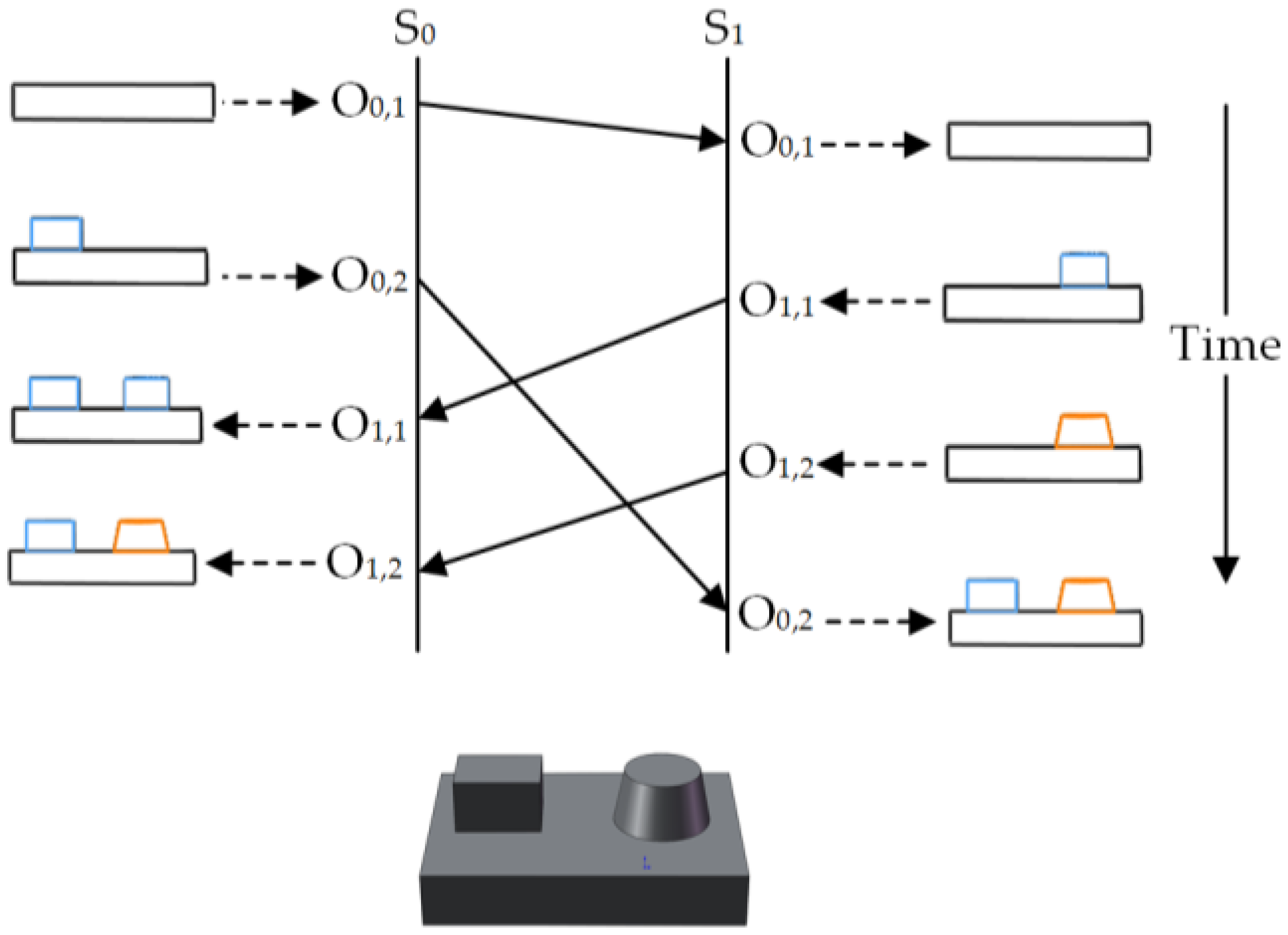
Suppose there is an arbitrary pair of modeling operations Oa and Ob sent by site Si and site Sj (Si ≠ Sj). When Oa and Ob satisfy neither Oa→Ob nor Ob→Oa, and Oa and Ob are executed on the same model states, there is a concurrency relationship between Oa and Ob, denoted as Oa‖Ob.
Suppose there is an arbitrary pair of modeling operations Oa and Ob sent by site Si and site Sj (Si ≠ Sj). If and only if Oa and Ob are executed on different model states, Oa and Ob are in a partial concurrency situation, denoted as Oa⊥Ob.
As shown in Figure 2, O0,2 creates Feature(O0,2) above Feature(O0,1) and O1,1 creates Feature(O1,1) above Feature(O0,1). According to the definition of a concurrency relationship, O0,2‖O1,1. O1,2 modifies Feature(O1,1) with a draft feature Feature(O1,2). For O0,2 and O1,2 are executed on different model states, giving O0,2⊥O1,1.
3.1.2. Dependency between Features
CAD systems are complex constraint systems and the mainstream CAD systems take modeling features as operating granularity. Therefore, in order to judge the relationship between modeling operations, this paper analyzes the constraint relationship between features. It is known that the constraint relationship between the features is dependency. While dealing with concurrent operations, it is necessary to judge whether there is a dependent relationship between the features of the remote operation and the features of the local operation. Then, the concurrent processing can be executed.
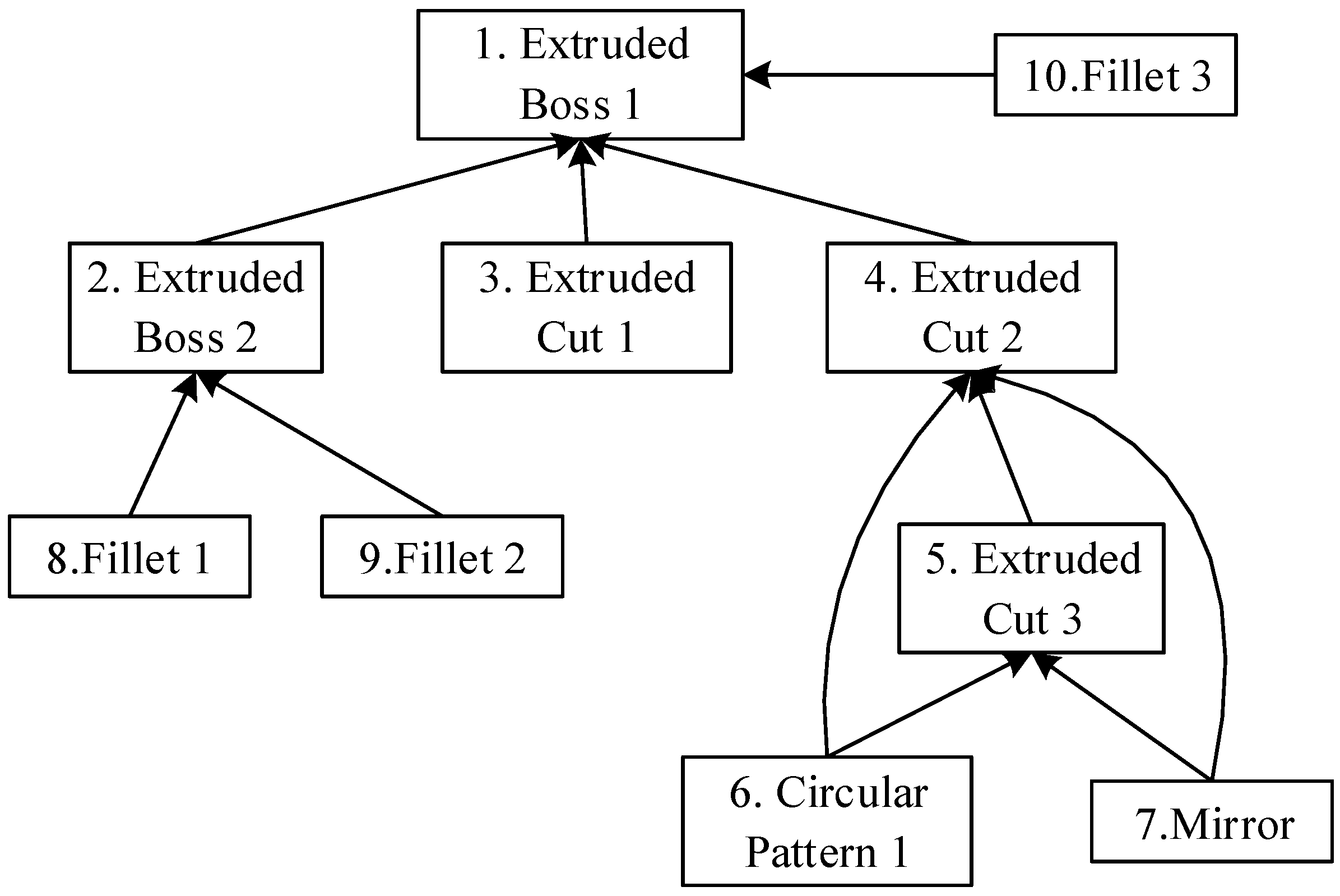
Figure 3 shows the feature-based modeling procedure of the cover of a gear pump, which includes 10 modeling steps. The dependent relationship of features can be mapped onto a directed graph, called a feature-dependent graph. When multiple sites execute modeling tasks collaboratively, each site maintains a collaborative feature-dependent graph (CoFDG). According to the feature dependencies in the model of Figure 3, the feature-dependent graph is shown in Figure 4. A feature-dependent graph has three important characteristics: partial order, transitive, and acyclic.
(1) Partial order
Partial order means the arbitrary dependency between two features are unidirectional, rather than mutual. There are two features, feature1 and feature2, in the model. If feature1 depends on feature2, feature2 does not depend on feature1, that is: feature1 < feature2 => feature2 ≮ feature1.
(2) Transitivity
Transitivity means the transmission of feature dependency is unidirectional. Set three arbitrary features in the model: feature1, feature2, and feature3; if feature1 depends on feature2 and feature2 depends on feature3, then feature1 depends on feature3, that is: feature1 < feature2&&feature2 < feature3 => feature1 < feature3. Among them, feature1 is directly dependent on feature2 and feature1 is indirectly dependent on feature3.
(3) Acyclic
Acyclic means that there is no cyclic dependency among the features of the model. Set three arbitrary features in the model: feature1, feature2, and feature3; if feature1 depends on feature2 and feature2 depends on feature3, then feature3 certainly does not depend on feature1.
In CAD systems, dependencies among features are established according to the feature modeling procedure. Only newly created features depend on existing features in the model, but an existing feature depends on a newly created feature or a feature not created yet.
3.1.3. Operation Queue
When a local modeling operation is executed on a collaborative site, the local site generates the corresponding modeling operation command and then sends it to other collaborative sites. According to Definition 3, the modeling operation command is <S, SV, Feature(O), T(O)>; these commands will be saved to the two queues.
● Collaborative Feature Operational List (CoFOL)
Each collaborative site holds a CoFOL for storing the executed operations. The executed modeling operation commands are stored in the CoFOL in accordance with their execution sequence.
● Collaborative Waiting Operational List (CoWOL)
Each collaborative site holds a CoWOL for storing operations waiting for execution. Those modeling operating commands that do not meet the execution conditions (e.g., non-causal) are placed in an execution queue, CoWOL. When the execution condition is satisfied, the operation command is removed from the CoWOL and executed.
3.2. Overall Methodology
In text-based co-editing, as long as the co-editing result is consistent, the order of operations of each site is irrelevant and insignificant. In Co-CAD, the order of operations for each site has greater significance for the following reasons:
- (1)
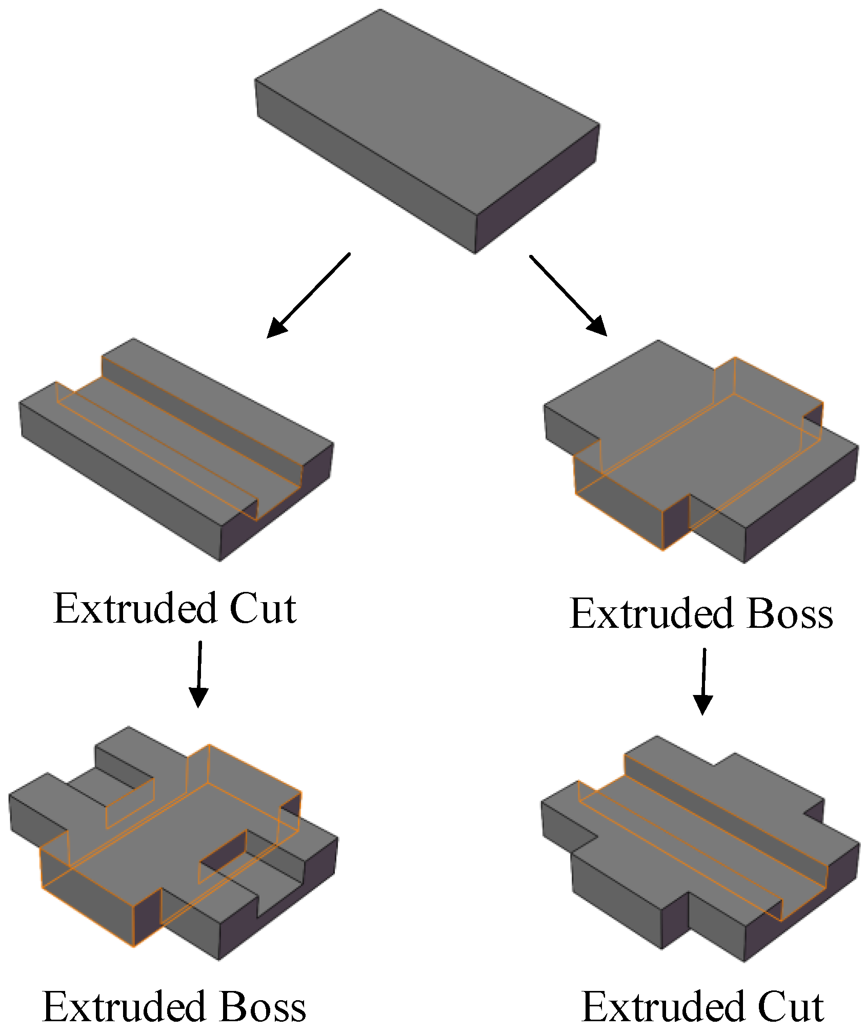
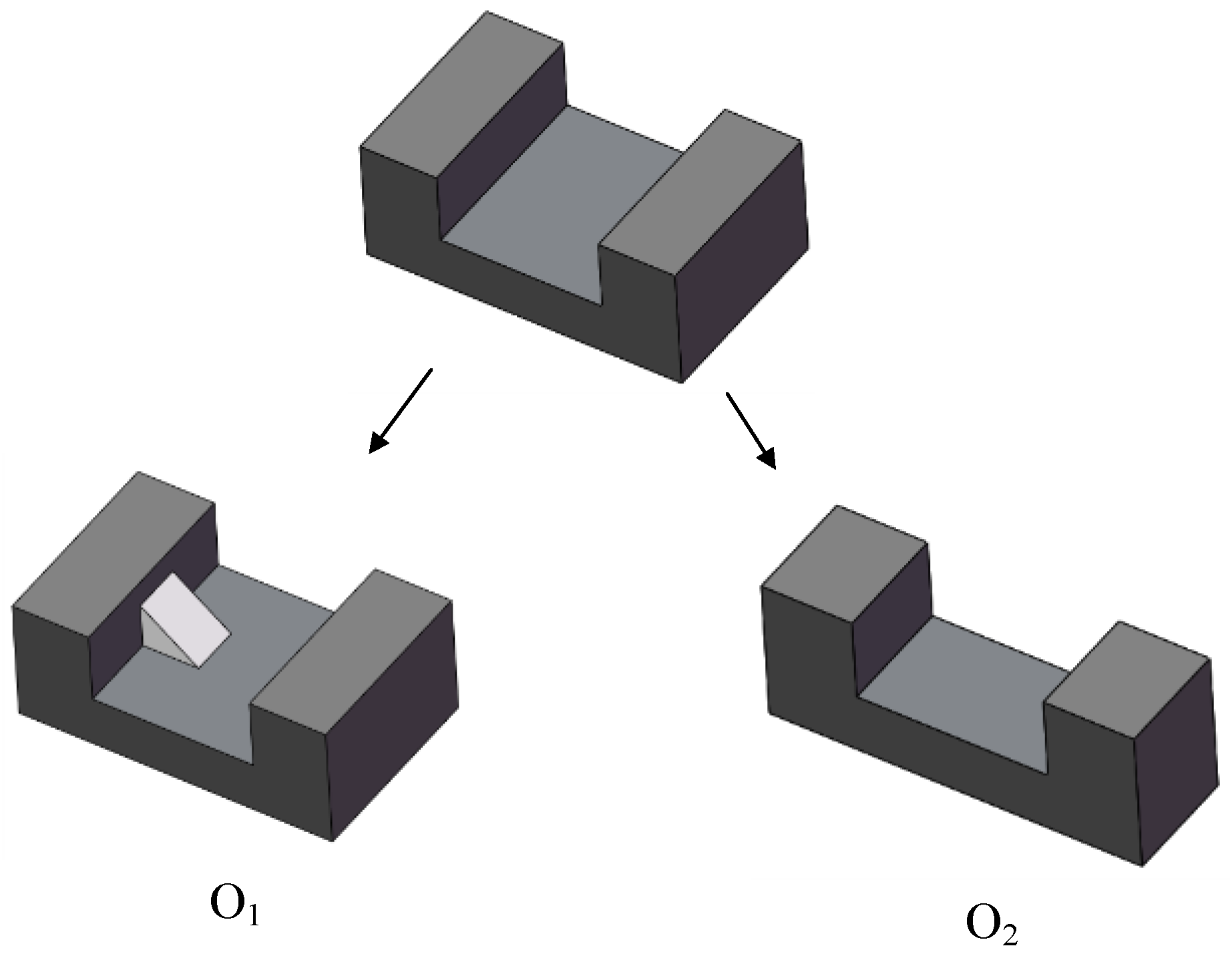
- Modeling features have a dependent relationship. Therefore, operations executed on features with dependency should follow the dependent relationship to keep a valid modeling procedure. As shown in Figure 5, the extruded cut feature depends on the initial boss feature. So, in the modeling procedure, the extruded cut must be executed after the creation of the boss feature. Otherwise, the cut operation is meaningless and non-executable.
- (2)
- Modeling operations may interact with each other. A different order of operations could lead to various modeling results. As shown in Figure 5, the different order of operations for the extruded cut and extruded boss create a dissimilar results model. Hence, a reasonable and unique modeling order should be determined in each site to produce consistent modeling results.
- (3)
- Moreover, during collaborative design, modeling operations from different sites may cause operational conflicts. As shown in Figure 6, operation O1 creates a rib feature in the slot of the initial model. O2 modifies the width of the initial model. Suppose O1 and O2 are from collaborative sites. Both operations are executable at their own sites but would trigger operational conflict because the rib does not intersect with the model after O2. In this situation, some operations are selected to be executed while others have to be revoked; all sites should conform to the same operation selection in their modeling procedure to maintain the consistency of the collaborative design results. In the case of Figure 6, either O1 or O2 has to be abandoned, and the other one is chosen to be executed.
- (4)
- The design history of a model is important information in Co-CAD, such as for the aspects of model reuse, modeling knowledge, intent sharing and so on. Therefore, it is important to maintain a consistent modeling history in each site of Co-CAD.
With the consideration of the pivotal role of the order of operations in Co-CAD, this paper proposed a Co-CAD synchronization model based on symmetric and consistent order of operations, as shown in Figure 7. The model maintains the causality of operations from local and remote sites. A concurrency control strategy is proposed to determine the unique order of operations within a concurrency relationship. Operations that would cause conflicts are abandoned for the validity of modeling.
Based on the consolidated causality order and concurrency processing, with the help of undo and redo operations, a symmetric and valid modeling procedure can be formed in all sites of Co-CAD. Consequently, with the same order of operations, unique modeling results could be obtained at each site. As a result, a valid model is obtained by collaborative design operations and each site of the Co-CAD maintains a consistent modeling history.
4. The Symmetric Synchronization Model
4.1. Causality Maintenance
According to Definition 5, there is a causality relationship between any two operations sent by one site. Suppose a local site Si sends out a series of operations O1, O2,…, On. When On reaches remote site Sj, if the current state vector on site Sj and the state vector of operating On satisfy: SVOn[i] = SVj[i] + 1 and SVOn[k] < SVj[k], k ∈ {1, 2,…, K}, k ≠ i, the operations sequence of Sj satisfies the causality of On. Namely, operations sequence O1, O2,…, On−1 from Si have been fully executed on site Sj. These conditions ensure that all operations prior to On have been fully executed on Sj.
4.2. Partial Concurrency Processing and Concurrent Operation Retrieving
Operations of collaborative text editing have a strict linear structure (depending on the location relationships among operations). The collaborative CAD modeling operations do not depend on the location relationship. Each site executes operations disorderly, without considering the impact of partial concurrency relationships on the collaborative modeling process. However, a partial concurrency relationship is one of the important reasons for inconsistent modeling history. The key to dealing with partial concurrency is to find the concurrent operation set of remote sites.
Scanning the CoFOL of the site (starting from the queue header), the location of modeling operations that are concurrent with remote operations can be retrieved based on the SV, denoted as n1. At this point, first execute an undo operation for all the modeling operations after n1 in CoFOL. Concurrency control is then executed based on concurrent relationships between operation CoFOL[n1] and operation O. Finally, execute a redo operation for all the undone modeling operations in CoFOL. The executed operations may cause the redo operation unable to be excuted. In this situation, the redo operation needs to be canceled.
4.3. Symmetric Concurrency Relationship Control Strategy
According to Definition 6, concurrent operations are executed on the same model state. On some occasions, concurrent operations reflect the concurrent collaboration of co-designers. On the other hand, diverse design intents from different sites may cause modeling conflicts. Hence, a concurrency control strategy is needed in collaborative design to maintain concurrent design intentions and avoid operational conflicts. Moreover, to maintain the consistency of the modeling history, the sequence of concurrent operations should be determined.
Set Oa and Ob are sent by site Si and site Sj, respectively, and Oa‖Ob. When Oa arrives at Sj, Oa has been executed in site Si. Similarly, when Ob arrives at Si, Ob has been executed in site Sj. Set Si is the local site and if in Si, Oa is executed before Ob, denoted as OaOb, then result model is denoted as Result(OaOb). Both Oa and Ob belong to {creation, modification, deletion}. Therefore, based on the operation type of Oa and Ob, there are nine situations for a concurrent operation pair, as shown in Figure 8. In Figure 8, the vertically listed capital letters “C,M,D” represent creation, modification, and deletion respectively, which are the three possible types of the local operation Oa. Likewise, the horizontal “C,M,D” means the three possible types of the remote operation Ob. Each grid table at the intersections of vertical and horizontal “C,M,D” represents one concurrent operation situation. For example, the grid table at the intersection of vertically listed C and horizontally listed M indicates that, in this situation, Oa is a creation operation and Ob is a modification operation.
After the classification of concurrent operations by type, the concurrent result should be further judged. For each concurrent operation pair, three factors are considered as the judging conditions of the concurrency control strategy:
- (1)
- Whether the operations are executed on the same modeling feature, denoted as “F” in the grids in Figure 8;
- (2)
- Whether the topological entities referenced by the remote operation exist, denoted as “T” in the grids in Figure 8;
- (3)
- Whether the features that are executed have a dependent relationship, denoted as “D” in the grids in Figure 8.
The grids in Figure 8 show the judging situations of concurrent operation pairs. The mark “√” in the grid table means the condition is satisfied while “×” means it is not. The three conditions should be judged according to a certain order—first F, then T, and finally D—as shown in Figure 8. In some cases, if not all factors need to be considered, then “/” is marked in the grid. For example, when Oa creates a new feature and Ob modifies an existing feature, they are surely not executed on the same feature. So Condition (1) is not necessary in this situation.
If the concurrent operations may cause conflict, the operation with higher priority is executed while the one with lower priority should be canceled to avoid conflicts. When concurrent operations can co-exist, to maintain a consistent modeling history, the operation with higher priority is executed before the one with lower priority. The operational priority can be determined by various factors. This paper uses site priority and dependency priority to determine the operational priority of concurrent operations. The operation from the site with higher priority or at the higher level of the collaborative feature-dependent graph has higher operational priority. When an operation is canceled or the order of operations is changed for consistency, the undo and redo mechanisms are needed.
The concurrency control solution of each judging result is shown in the last row of grid tables, denoted as S. The numbers 1, 2, 3, 4, and 5 indicate five different solutions. To illustrate the solutions, set Si has a higher site priority and Oa has higher dependency priority. The five solutions are:
- (1)
- Both operations are executed; rank the order of operations according to site priority. In Si, there is OaOb. In Sj, first execute an undo operation to Ob, then execute Oa, finally redo Ob. The final order of operations is OaOb and the result is Result(OaOb).
- (2)
- Execute the operation from the site with higher priority. In Si, Ob is undone. In Sj, Ob is undone and Oa is executed. The final order of operations is Oa and the result is Result(Oa).
- (3)
- Execute the operation with higher dependency priority. In Si, Ob is undone. In Sj, Ob is undone and Oa is executed. The final order of operations is Oa and the result is Result(Oa).
- (4)
- Both operations are executed and ranked according to dependency priority. In Si, there is OaOb. In Sj, first execute an undo operation to Ob, then execute Oa, finally redo Ob. When we redo Ob, it may be not executable because of Oa. In this situation, Ob needs to be abandoned. So, the final order of operations is OaOb or Oa and the result is Result(OaOb) or Result(Oa).
- (5)
- Both operations are executed and ranked in reversed order of site priority. In Si, first execute an undo operation to Oa, then execute Ob, finally redo Oa. In Si, there is ObOa. When we redo Oa, it may be not executable because of Ob. In this situation, Ob needs to be abandoned, then we can redo Oa. So, the final order of operations is ObOa or Oa and the result is Result(ObOa) or Result(Oa).
With the proposed synchronization model, collaborative operations that may cause conflict will be discarded. So the resulting model will be a valid one.
In the CoFOL of each site, the operations follow the causality based on modeling state vectors. To those concurrent operations with the same state vectors, the proposed concurrent control strategy gives the operation selection or order solutions for every concurrent situation.
The causality of operations is the same at different sites. Moreover, the operation selection or order of concurrent operations is unique according to the proposed concurrent control strategy. Combining these two aspects, the CoFOL of each Co-CAD site is identical, which means the modeling procedure is consistent and symmetric among different sites. With symmetric modeling for the order of operations, consistency is achieved in Co-CAD.
4.4. Operation Execution of Local and Remote Site
The proposed symmetric synchronization for Co-CAD includes local site execution and remote site execution. Local operation is executed immediately for high response and the state vector should be updated (SVi[i++]). Meanwhile, the operation is sent to other remote sites.
Figure 9 shows the remote site execution procedure. To maintain the causal relationship for all sites, if the operations before the remote operation (causal operations) have not been fully integrated into CoFOL, add this operation to CoWOL until the causality relationship is fully satisfied. When the causality of the received remote operation is fully satisfied, if the remote operation is partially concurrent, partial concurrency processing is required. If the remote operation is concurrent, it is necessary to retrieve the operation that has been executed and is concurrent to the remote operation in current site, then use the concurrency control strategy for processing.
5. Case Study and Analysis
5.1. Case Study
A case study of collaborative design application is shown to verify the maintenance of consistency. In this case study, set site S0 and site S1 are two collaborative sites to design a gear pump base. Because the case study contains many operations, the whole collaboration process is shown in Figure 10, Figure 11, Figure 12 and Figure 13. In these figures, the collaborative design procedures of the two sites are on the left side and the dashed boxes on the right side show the modeling history. The capital letters “C”, “M,” or “D” under each operation indicate the operation type, as in Figure 8. SolidWorks is chosen as the CAD systems. Set Priority(S0) > Priority(S1) and both sites store a shared model.
In Figure 10, O0,1 from S0 creates an extruded boss (Feature(O0,1)). O0,2 created an extruded cut (Feature(O0,2)) on Feature(O0,1). In S1, O1,1 create an extruded boss (Feature(O1,1)) and an extruded cut (Feature(O1,2)) on the arrived Feature(O0,1).
O1,2 arrives at S0 before O1,1. O1,1 is the concurrent operation of O0,2. O1,2 is put into CoWOL first. Both O0,2 and O1,1 are creation operations and the topological entity needed by O1,1 exists. So, according to the proposed concurrency control strategy, both operations are executed and the order is O0,2O1,1. Then O1,2 is taken out of CoWOL and executed. However, the topological face required by O1,2 has been changed by O0,2. In S1, because Priority(O0,2) > Priority(O1,1), O1,1 and O1,2 are undone first. Then execute O0,2 and redo O1,1 and O1,2. Because O1,2 cannot be executed, it is canceled.
The collaborative design continues in Figure 11. O0,3 creates an extruded cut (Feature(O0,3)) and O0,4 creates a circular pattern (Feature(O0,4)) for Feature(O0,3). In S1, O1,3 deletes Feature(O0,3). O1,3 and O0,4 are concurrent operations. Because Feature(O0,4) depends on Feature(O0,3), O1,3 has a higher dependency priority. So O1,3 is executed in both sites and O0,4 is undone, as shown in the figure.
O1,4 creates a threaded hole (Feature(O1,4)) and O1,5 makes a pattern of Feature(O1,4) (Feature(O1,5)). O0,5 and O0,6 create two extruded bosses. O1,4 and O0,5 are concurrent operations. The collaborative process based on concurrency control strategy is shown in the figure.
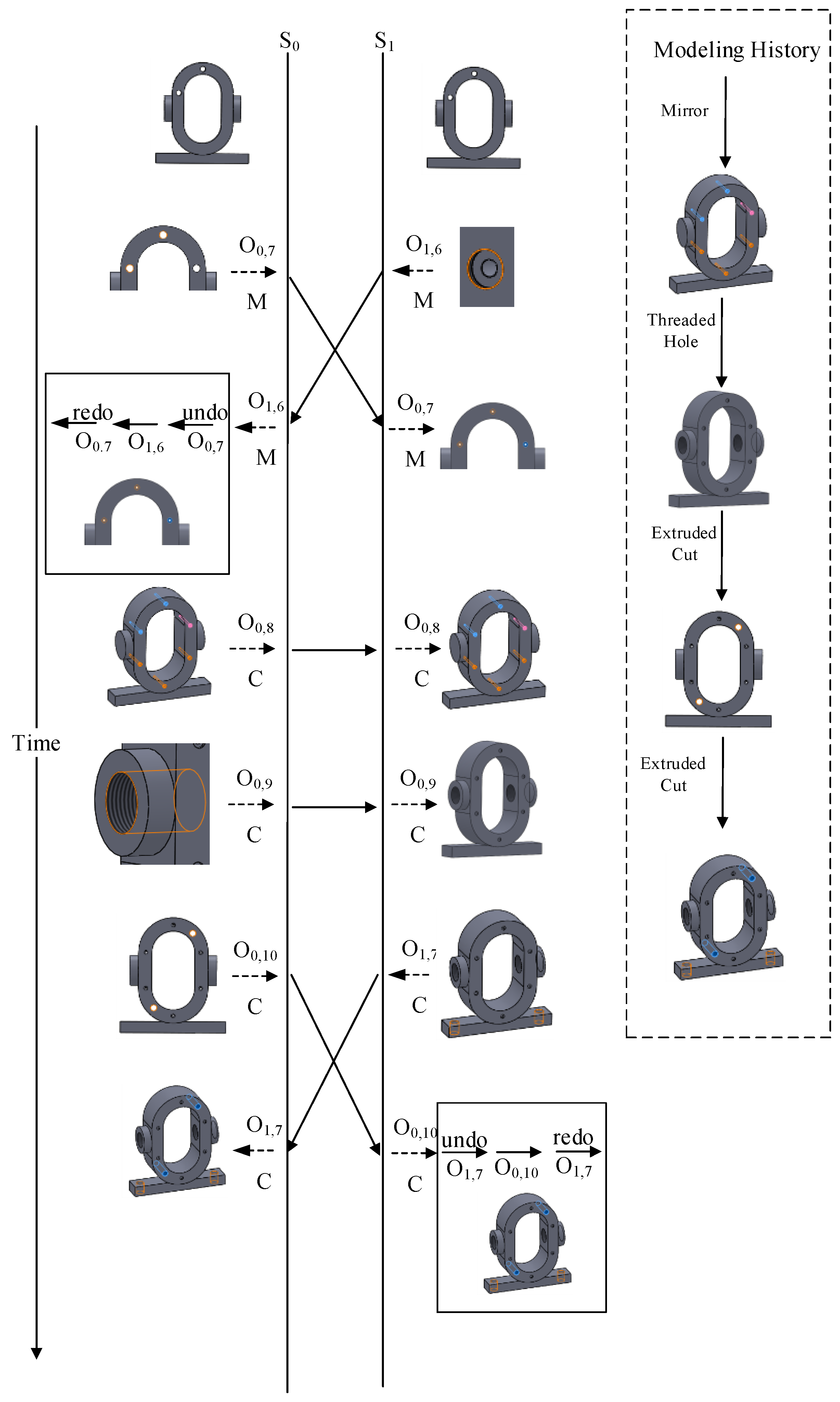
Figure 12 shows the following steps after Figure 11. O0,7 and O1,6 are two concurrent modification operations. O1,6 modifies Feature(O1,4) and O0,7 modifies Feature(O1,5). Because of the dependent relationship of Feature(O1,4) and Feature(O1,5), O1,6 should be executed before O1,5. O0,10 and O1,7 are concurrent and the concurrency control result is shown in the figure.
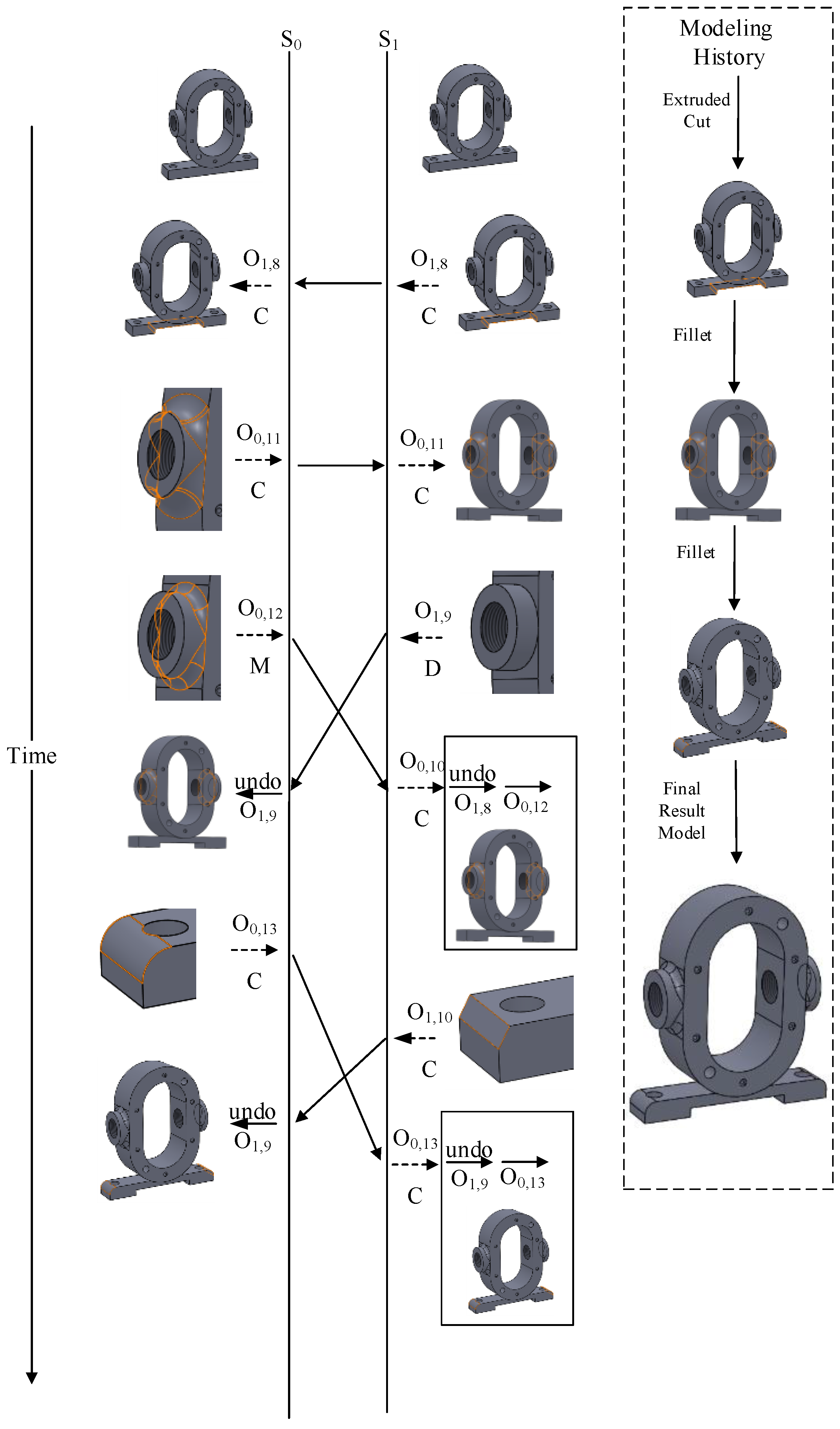
Figure 13 shows the final steps of the collaborative design process. O0,12 is a modification operation and O1,9 is a deletion operation. They are concurrent and both executed on the same feature Feature(O0,11). Because S0 has the higher priority, O0.12 is chosen to be executed. O0,13 creates a fillet (Feature(O0,13)) while O1,9 creates a chamfer (Feature(O1,10)) on the same feature. When O1,9 arrives at S0, the topological edge needed to create Feature(O1,10) is lost because of O0,13. The situation is the same when O0,13 arrives at S1 to create Feature(O0,13) after O1,9 has been executed there. Because Priority(O0,13) > Priority(O1,10), the fillet is created and the chamfer is withdrawn.
Through the described and shown collaborative modeling procedure, the final result model of a gear pump bass is created by symmetric modeling procedure of two sites collaboratively. In the whole procedure of this case study, the modeling history of all sites is:
- {O0,1,O0,2,O1,1,O0,5,O1,4,O0,6,O1,5,O0,8,O0,9,O0,10,O1,7,O1,8,O0,11,O0,13}.
The symmetric CoFOL of operations in each site are:
- S0: {O0,1,O0,2,O1,1,O0,3,O1,3,O0,5,O1,4,O0,6,O1,5,O1,6,O0,7,O0,8,O0,9,O0,10,O1,7,O1,8,O0,11,O0,12,O0,13},
- S1: {O0,1,O0,2,O1,1,O0,3,O1,3,O0,5,O1,4,O0,6,O1,5,O1,6,O0,7,O0,8,O0,9,O0,10,O1,7,O1,8,O0,11,O0,12,O0,13}.
Thus, in S0 and S1, a consistent result model is generated collaboratively by symmetric operations and the modeling history is consistent in both sites.
5.2. Comparisons and Analysis
5.2.1. General Discussion
In our work, the local operations are executed immediately and directly sent to other sites. So the burden of network transmission and response time of each site is effectively reduced. In a centralized architecture, every site is required to send operations to a centralized server and the server broadcasts operations to all sites.
The authority-based methods (such as lock mechanisms and floor mechanisms) can also maintain consistent order of operations by giving editing authority to one user at a time. The proposed method supports multi-user editing of the shared CAD model simultaneously.
The proposed method uses a symmetric operation procedure for modeling consistency. All the operations are based on the granularity of modeling features. The method is more convenient than the OT-based replicated Co-CAD method, which requires complex geometry computation and collaborative naming methods.
More specific discussions are given in the following sub-sections.
5.2.2. Architecture and Strategy
This paper maintains a consistent modeling order of operations to achieve consistent result. The difference between this paper and the most closely related reference [13] is that our method is based on peer-to-peer replicated architecture, in which we have to face new technical challenges. The detailed differences are analyzed and compared as follows.
Firstly, [13] adopts a replicated architecture with a centralized server used to coordinate the collaborative CAD operations and sends the global order of operations to all design sites. Therefore, the modeling history of each site is automatically consistent. By contrast, our paper is based on peer-to-peer replicated architecture, in which there is no centralized server. Hence, our work emphasizes how to maintain consistent modeling history in collaborative design and researches on the convenient approach that can achieve Co-CAD consistency for every Co-CAD site. Then, a set of operation ordering rules is proposed to keep operations in a consistent and valid order in all sites. Consequently, with consistent operational order maintained in every site, the consistency of both history and results is achieved.
Secondly, [13] uses the time that operations come to the server as the fundamental judgement criterion. The coordination of operations from design sites is achieved by the matching and updating of the Operation Sequence Number (OSN) on the service and received operational sequence number (ROSN) on the client. Our paper introduces some proper technique issues for the peer-to-peer replicated architecture. The state vector is used in Co-CAD to indicate modeling status. Based on the state vector, three operational relationships, causality, concurrency, and partial concurrency, are determined. Operation sequence is re-organized based on the operational relationship in each site. The order of operations must conform to causality at first. In partial concurrency processing, the concurrent operation of a received remote operation can be found in the operational sequence. To the concurrent operations, we proposed the symmetric concurrency relationship control strategy to determine the order of operations. The site priority and operation dependency are both used as judgment criteria.
5.2.3. Conflict Resolution
The conflict resolution mechanism is an important part of Co-CAD systems. Operational conflicts can be classified as different types based on different taxonomies. For example, according to [13], operational conflict can be classified into two types, “a semantic conflict is caused by valid operations which violate the design intent of a model, leading to redundant work; a syntactic conflict happens between operations that cause one or more operations to become invalid” [13] (p. 2). This manuscript keeps the above roadmap and presents a novel approach to ensure consistent and valid modeling results in Co-CAD.
For semantic conflict, it is difficult for a Co-CAD system to determine whether the design intent is correct or not. The fundamental function of the system is to maintain consistent results for all of sites/users. The “consistent results” can be “correct” or “not correct” from the view of design intent. After a number of human–human interaction [7,19] processes, the sites/users can reach a compromised result. Because the mutual perception (collaborative awareness) is an important issue to support human–human interaction processes, we try to preserve the operations as much as possible. Then, when semantic conflict occurs, the designers can observe it. Therefore, the semantic conflict will finally be resolved by the designers themselves.
Potential syntactic conflicts are detected during the process of operation ordering in this paper. Three judging conditions (the existence of a referenced topological entity, the operational object, and the dependent relationship) are presented to determine whether there will be a conflict taking place when executing concurrent remote operations. Syntactic conflict means that collaborative operations are mutually exclusive. In other words, one or more operations cannot be executed. So at least one of the conflicted operations has to be discarded in order to maintain the feature validity. Therefore, the next key issue is how to determine which one to abandon. Our method uses site priority and dependency priority as the determination criteria. The above judging conditions and determination criteria are based on the essential execution conditions of feature operation and reasonable Co-CAD design scene.
6. Conclusions
This paper proposed a novel synchronization mechanism for Co-CAD with the consideration of modeling history. Relationships of collaborative operations are analyzed first. Modeling state vector and operation queue are used for causality relationship maintenance, partial concurrency processing, and retrieving concurrent operation. A symmetric concurrency relationship control strategy is proposed to determine the concurrent operation sequence. For every possible situation of concurrent operations, a corresponding solution is given based on the proposed judging conditions and operational priority. The strategy sorts the execution order of concurrent operations, and determines operations that may cause conflicts.
After processing collaborative operations by the proposed method, a symmetric and consistent modeling procedure is generated in each Co-CAD site. Thereby, the consistency of both modeling results and procedures is achieved. The design intents of all sites are preserved, except for those that will lead to operational conflict. The proposed mechanism is effective, convenient, and practical.
As to future research directions, firstly it is necessary to accelerate and optimize the proposed method with paralleling computing [52,53,54,55,56] and intelligent computing [57,58,59,60] because the frequent use of undo and redo operations will increase computational costs. Secondly, the security problem in collaboration design [61,62,63] will be researched in the future. Thirdly, discarding features for conflict resolution is not perfect for mutual perception in Co-CAD, so research can be improved to preserve design intents from all collaborative sites as much as possible. Fourthly, we also want to extend our method to a hybrid synchronous CAD environment [8]. Finally, we also want to extend the symmetry- and consistency-related methods to other areas of science and technology [64,65,66,67,68,69,70,71].
Acknowledgments
This paper was supported by the National Science Foundation of China (Grant No. 61472289), the National Key Research and Development Project (Grant No. 2016YFC0106305), and the Open Project Program of the State Key Laboratory of Digital Manufacturing Equipment and Technology at HUST (Grant No. DMETKF2017016).
Author Contributions
Yiqi Wu and Fazhi He proposed the main idea. Fazhi He and Soonhung Han supervised the research and Yiqi Wu wrote the manuscript. All authors have approved the final manuscript.
Conflicts of Interest
The authors declare no conflict of interest.
References
- Zeng, Y.; Horváth, I. Fundamentals of next generation CAD/E systems. Comput. Aided Des. 2012, 44, 875–878. [Google Scholar] [CrossRef]
- Lee, S.; Jeong, T. Cloud-Based Parameter-Driven Statistical Services and Resource Allocation in a Heterogeneous Platform on Enterprise Environment. Symmetry 2016, 8, 103. [Google Scholar] [CrossRef]
- Li, W.D.; Mehnen, J. Cloud Manufacturing (Springer Series in Advanced Manufacturing); Springer: London, UK, 2013. [Google Scholar]
- Grudin, J. Computer-supported cooperative work: History and focus. Computer 1994, 27, 19–26. [Google Scholar] [CrossRef]
- Red, E.; French, D.; Hepworth, A. Multi-User Computer-Aided Design and Engineering Software Applications. In Cloud-Based Design and Manufacturing (CBDM); Dirk, S., Ed.; Springer: Berlin, Germany, 2014; pp. 25–62. [Google Scholar]
- Li, W.D.; Lu, W.F.; Fuh, J.Y.H.; Wong, Y.S. Collaborative computer-aided design—Research and development status. Comput. Aided Des. 2005, 37, 931–940. [Google Scholar] [CrossRef]
- He, F.Z.; Han, S.H. A method and tool for human-human interaction and instant collaboration in CSCW based CAD. Comput. Ind. 2006, 57, 740–751. [Google Scholar] [CrossRef]
- Gao, L.; Shao, B.; Zhu, L.; Lu, T.; Gu, N. Maintaining time and space consistencies in hybrid CAD environments: Framework and algorithms. Comput. Ind. 2008, 59, 894–904. [Google Scholar] [CrossRef]
- Wu, Y.; He, F.; Zhang, D.; Li, X. Service-oriented feature-based data exchange for cloud-based design and manufacturing. IEEE Trans. Serv. Comput. 2015. [Google Scholar] [CrossRef]
- Gao, L.; Yu, F.; Chen, Q.; Xiong, N. Consistency maintenance of Do and Undo/Redo operations in real-time collaborative bitmap editing systems. Clust. Comput. 2016, 19, 255–267. [Google Scholar] [CrossRef]
- Gao, L.; Yu, F.; Gao, L.; Xiong, N.; Yang, G. Consistency maintenance of compound operations in real-time collaborative environments. Comput. Electr. Eng. 2016, 50, 217–235. [Google Scholar] [CrossRef]
- Lv, X.; He, F.; Cai, W.; Chen, Y. A string-wise CRDT algorithm for smart and large-scale collaborative editing systems. Adv. Eng. Inform. 2016. [Google Scholar] [CrossRef]
- Hepworth, A.; Tew, K.; Trent, M.; Ricks, D.; Jensen, G. Model consistency and conflict resolution with data preservation in multi-user computer aided design. J. Comput. Inf. Sci. Eng. 2014, 14, 021008. [Google Scholar] [CrossRef]
- Gao, L.; Lu, T.; Gu, N. CLAF: Solving intention violation of step-wise operations in CAD groupware. Adv. Eng. Inform. 2010, 24, 121–137. [Google Scholar] [CrossRef]
- Jing, S.X.; He, F.Z.; Han, S.H. A method for topological entity correspondence in a replicated collaborative CAD system. Comput. Ind. 2009, 60, 467–475. [Google Scholar] [CrossRef]
- Li, X.; He, F.; Cai, X.; Zhang, D.; Chen, Y. A method for topological entity matching in the integration of heterogeneous cad systems. Integr. Comput. Aided Eng. 2013, 20, 15–30. [Google Scholar]
- Wang, Y.; Nnaji, B.O. Geometry-based semantic ID for persistent and interoperable reference in feature-based parametric modeling. Comput. Aided Des. 2005, 37, 1081–1093. [Google Scholar] [CrossRef]
- Tessier, S.; Wang, Y. Ontology-based feature mapping and verification between CAD systems. Adv. Eng. Inform. 2013, 27, 76–92. [Google Scholar] [CrossRef]
- Cheng, Y.; He, F.; Wu, Y. Meta-operation conflict resolution for human–human interaction in collaborative feature-based CAD systems. Clust. Comput. 2016, 19, 237–253. [Google Scholar] [CrossRef]
- Zhang, D.J.; He, F.Z.; Han, S.H.; Li, X.X. Quantitative optimization of interoperability during feature-based data exchange. Integr. Comput. Aided Eng. 2016, 23, 31–50. [Google Scholar] [CrossRef]
- Chen, Y.; He, F.; Wu, Y.; Hou, N. A local start search algorithm to compute exact Hausdorff Distance for arbitrary point sets. Pattern Recognit. 2017, 67, 139–148. [Google Scholar] [CrossRef]
- Red, E.; French, D.; Jensen, G.; Walker, S.; Madsen, P. Emerging design methods and tools in collaborative product development. J. Comput. Inf. Sci. Eng. 2013, 13, 031001. [Google Scholar] [CrossRef]
- Kim, B.C.; Mun, D. Stepwise volume decomposition for the modification of B-rep models. Int. J. Adv. Manuf. Technol. 2014, 75, 1393–1403. [Google Scholar] [CrossRef]
- Yeoun, Y.; Kim, B.C. CAD model simplification using feature simplifications. J. Adv. Mech. Des. Syst. 2016, 10, JAMDSM0099. [Google Scholar]
- Shen, W.M.; Hao, Q. Computer support collaborative design: Retrospective and perspective. Comput. Ind. 2008, 9, 855–862. [Google Scholar] [CrossRef]
- Dietrich, U.; Von Lukas, U.; Morche, I. Cooperative modeling with TOBACO. In Proceedings of the TeamCAD97 Workshop on Collaborative Design, Atlanta, GA, USA, 12–13 May 1997; pp. 115–122. [Google Scholar]
- Stork, A.; Lukas, U.; Schultz, R. Enhancing a commercial 3D CAD system by CSCW functionality for enabling co-operative modelling via WAN. In Proceedings of the ASME Design Engineering Technical Conferences, Atlanta, GA, USA, 13–16 September 1998. [Google Scholar]
- Stork, A.; Jasnoch, U. A collaborative engineering environment. In Proceedings of the TeamCAD97 Workshop on Collaborative Design, Atlanta, GA, USA, 12–13 May 1997; pp. 25–33. [Google Scholar]
- Li, M.; Gao, S.H.; Wang, C.C. Real-Time Collaborative Design With Heterogeneous CAD Systems Based on Neutral Modeling Commands. J. Comput. Inf. Sci. Eng. 2007, 7, 113–125. [Google Scholar] [CrossRef]
- Li, M.; Gao, S.; Fuh, J.Y.H. Replicated Concurrency Control for Collaborative Feature Modeling: A Fine Granular Approach. Comput. Ind. 2008, 59, 873–881. [Google Scholar] [CrossRef]
- Yang, L.; Ong, S.K.; Nee, A.Y.C. Coordination for replicated collaborative feature modeling. Int. J. Interact. Des. Manuf. 2010, 4, 191–200. [Google Scholar] [CrossRef]
- Li, D.; Li, R. An admissibility-based operational transformation framework for collaborative editing systems. Comput. Support. Coop. Work (CSCW) 2010, 19, 1–43. [Google Scholar] [CrossRef]
- Shao, B.; Li, D.; Gu, N. A sequence transformation algorithm for supporting cooperative work on mobile devices. In Proceedings of the 2010 ACM Conference on Computer Supported Cooperative Work, Savannah, GA, USA, 6–10 February 2010. [Google Scholar]
- Shao, B.; Li, D.; Lu, T.; Gu, N. An operational transformation based synchronization protocol for web 2.0 applications. In Proceedings of the ACM 2011 Conference on Computer Supported Cooperative Work, Hangzhou, China, 19–23 March 2011. [Google Scholar]
- Sun, D.; Sun, C.; Xia, S.; Shen, H. Creative conflict resolution in collaborative editing systems. In Proceedings of the ACM 2012 Conference on Computer Supported Cooperative Work, Seattle, WA, USA, 11–15 February 2012. [Google Scholar]
- Suleiman, M.; Cart, M.; Ferri’e, J. Serialization of concurrent operations in a distributed collaborative environment. In Proceedings of the International ACM SIGGROUP Conference on Supporting Group Work: The Integration Challenge, Phoenix, AZ, USA, 16–19 November 1997; pp. 435–445. [Google Scholar]
- Vidot, N.; Cart, M.; Ferri’e, J. Copies convergence in a distributed real-time collaborative environment. In Proceedings of the ACM 2000 Conference on Computer Supported Cooperative Work, Philadelphia, PA, USA, 2–6 December 2000; pp. 171–180. [Google Scholar]
- Preguica, N.; Marques, J.M.; Shapiro, M. A commutative replicated data type for cooperative editing. In Proceedings of the 29th IEEE International Conference on Distributed Computing Systems (ICDCS), Montreal, QC, Canada, 22–26 June 2009; pp. 395–403. [Google Scholar]
- Oster, G.; Urso, P.; Molli, P. Data consistency for P2P collaborative editing. In Proceedings of the 20th Anniversary Conference on Computer Supported Cooperative Work, Banff, AB, Canada, 4–8 November 2006; pp. 259–268. [Google Scholar]
- Weiss, S.; Urso, P.; Molli, P. Logoot-undo: Distributed collaborative editing system on p2p networks. IEEE Trans. Parallel Distrib. Syst. 2010, 21, 1162–1174. [Google Scholar] [CrossRef]
- Liu, H.; He, F.; Zhu, F. Consistency maintenance in collaborative CAD systems. Chin. J. Electron. 2013, 22, 15–20. [Google Scholar]
- Sun, C.; Xu, D. Operational transformation for dependency conflict resolution in real-time collaborative 3D design systems. In Proceedings of the ACM 2012 conference on Computer Supported Cooperative Work, Seattle, WA, USA, 11–14 February 2012. [Google Scholar]
- Brosch, P.; Seidl, M.; Wieland, K.; Wimmer, M.; Langer, P. We can work it out: Collaborative conflict resolution in model versioning. In ECSCW 2009; Springer: Vienna, Austria, 2009; pp. 207–214. [Google Scholar]
- Trappey, A.J.; Trappey, C.V.; Wu, C.-Y.; Fan, C.Y.; Lin, Y.-L. Intelligent patent recommendation system for innovative design collaboration. J. Netw. Comput. Appl. 2013, 36, 1441–1450. [Google Scholar] [CrossRef]
- Hepworth, A.I.; Tew, K.; Nysetvold, T.; Bennett, M.; Jensen, C.G. Automated conflict avoidance in multi-user CAD. Comput. Aided Des. Appl. 2014, 11, 141–152. [Google Scholar] [CrossRef]
- Moncur, R.A.; Jensen, C.G.; Teng, C.C.; Red, E. Data consistency and conflict avoidance in a multi-user CAx environment. Comput. Aided Des. Appl. 2013, 10, 727–744. [Google Scholar] [CrossRef]
- Yu, M.; Cai, H.; Ma, X.; Jiang, L. Symmetry-Based Conflict Detection and Resolution Method towards Web3D-based Collaborative Design. Symmetry 2016, 8, 35. [Google Scholar] [CrossRef]
- Cai, X.T.; Li, X.X.; He, F.Z. Flexible concurrency control for legacy CAD to construct collaborative CAD environment. J. Adv. Mech. Des. Syst. 2012, 6, 324–339. [Google Scholar] [CrossRef]
- Lee, H.; Kim, J.; Banerjee, A. Collaborative intelligent CAD framework incorporating design history tracking algorithm. Comput. Aided Des. 2010, 42, 1125–1142. [Google Scholar] [CrossRef]
- Lamport, L. Time, clocks, and the ordering of events in a distributed system. Commun. ACM 1978, 21, 558–565. [Google Scholar] [CrossRef]
- Sun, C.; Zhang, Y.; Jia, X. A generic operation transformation scheme for consistency maintenance in real-time cooperative editing systems. In Proceedings of the International ACM SIGGROUP Conference on Supporting Group Work: The integration challenge, Phoenix, AZ, USA, 16–19 November 1997; pp. 425–434. [Google Scholar]
- Zhou, Y.; He, F.; Qiu, Y. Optimization of parallel iterated local search algorithms on graphics processing unit. J. Supercomput. 2016, 72, 2394–2416. [Google Scholar] [CrossRef]
- Zhou, Y.; He, F.; Qiu, Y. Dynamic Strategy based Parallel Ant Colony Optimization on GPUs for TSPs. Sci. China Inf. Sci. 2017, 60, 068102. [Google Scholar] [CrossRef]
- Cai, W.; He, F.; Lv, X. Multi-core Accelerated Operational Transformation for Collaborative Editing. In Proceedings of the International Conference on Collaborative Computing: Networking, Applications and Worksharing, Wuhan, China, 10–11 November 2015; Springer International Publishing: New York, NY, USA, 2015; pp. 121–128. [Google Scholar]
- Chen, G.; Li, G.; Wu, B.; Pei, S. A GPU-based computing framework for CSCW. In Proceedings of the 14th International Conference on Computer Supported Cooperative Work in Design, Shanghai, China, 14–16 April 2010; pp. 100–103. [Google Scholar]
- Pinheiro, A.; Desterro, F.; Santos, M.; Pereira, C.; Schirru, R. GPU-Based Parallel Computation in Real-Time Modeling of Atmospheric Radionuclide Dispersion. In Advances in Human Factors and System Interactions; Nunes, I.L., Ed.; Springer: Cham, Switzerland, 2017; Volume 497, pp. 323–333. [Google Scholar]
- Yan, X.; He, F.; Chen, Y.; Yuan, Z. An efficient improved particle swarm optimization based on prey behavior of fish schooling. J. Adv. Mech. Des. Syst. 2015, 9, JAMDSM0048. [Google Scholar] [CrossRef]
- Yan, X.; He, F.; Hou, N. A novel hardware/software partitioning method based on position disturbed particle swarm optimization with invasive weed optimization. J. Comput. Sci. Technol. 2017, 32, 340–355. [Google Scholar] [CrossRef]
- Yan, X.; He, F.; Hou, N.; Ai, H. An efficient particle swarm optimization for large scale hardware/software codesign system. Int. J. Coop. Inf. Syst. 2017. [Google Scholar]
- Wang, D.; Tan, D.; Liu, L. Particle swarm optimization algorithm: An overview. Soft Comput. 2017. [Google Scholar] [CrossRef]
- Mun, D.; Hwang, J.; Han, S. Protection of intellectual property based on a skeleton model in product design collaboration. Comput. Aided Des. 2009, 41, 641–648. [Google Scholar] [CrossRef]
- Cai, X.T.; Wang, S.; Lu, X.; Li, W.D. Parametric Encryption of CAD models in Cloud manufacturing environment. In Proceedings of the 20th International Conference on Computer Supported Cooperative Work in Design, Nanchang, China, 4–6 May 2016; pp. 551–556. [Google Scholar]
- Park, J.H.; Kim, H.; Kang, J. Security scheme based on parameter hiding technic for mobile communication in a secure cyber world. Symmetry 2016, 8, 106. [Google Scholar] [CrossRef]
- Li, K.; He, F. Robust Visual Tracking based on convolutional features with illumination and occlusion handing. J. Comput. Sci. Technol. 2017. accepted. [Google Scholar]
- Li, K.; He, F.; Yu, H.; Chen, X. A correlative classiers approach based on particle filter and sample set for tracking occluded target. Appl. Math. Ser. B 2017. accepted. [Google Scholar]
- Yu, H.; He, F.; Pan, Y.; Chen, X. An efficient similarity-based level set model for medical image segmentation. J. Adv. Mech. Des. Syst. 2016, 10, JAMDSM0100. [Google Scholar] [CrossRef]
- Li, K.; He, F.; Chen, X. Real-time object tracking via compressive feature selection. Front. Comput. Sci. 2016, 10, 689–701. [Google Scholar] [CrossRef]
- Sun, J.; He, F.Z.; Chen, Y.L.; Chen, X. A multiple template approach for robust tracking of fast motion target. Appl. Math. Ser. B 2016, 31, 177–197. [Google Scholar] [CrossRef]
- Ni, B.; He, F.Z.; Pan, Y.T.; Yuan, Z.Y. Using shapes correlation for active contour segmentation of uterine fibroid ultrasound images in computer-aided therapy. Appl. Math. J. Chin. Univ. 2016, 31, 37–52. [Google Scholar] [CrossRef]
- Ni, B.; He, F.Z.; Yuan, Z.Y. Segmentation of uterine fibroid ultrasound images using a dynamic statistical shape model in HIFU therapy. Comput. Med. Imaging Graph. 2015, 46, 302–314. [Google Scholar] [CrossRef] [PubMed]
- Zhang, D.J.; He, F.Z.; Han, S.H.; Zou, L.; Wu, Y.Q.; Chen, Y.L. An efficient approach to directly compute the exact Hausdorff distance for 3D point sets. Integr. Comput. Aided E 2017. accepted. [Google Scholar]
Figure 1.
Causality relationship.

Figure 2.
Concurrency and partial concurrency relationships.

Figure 3.
Feature-based modeling process.
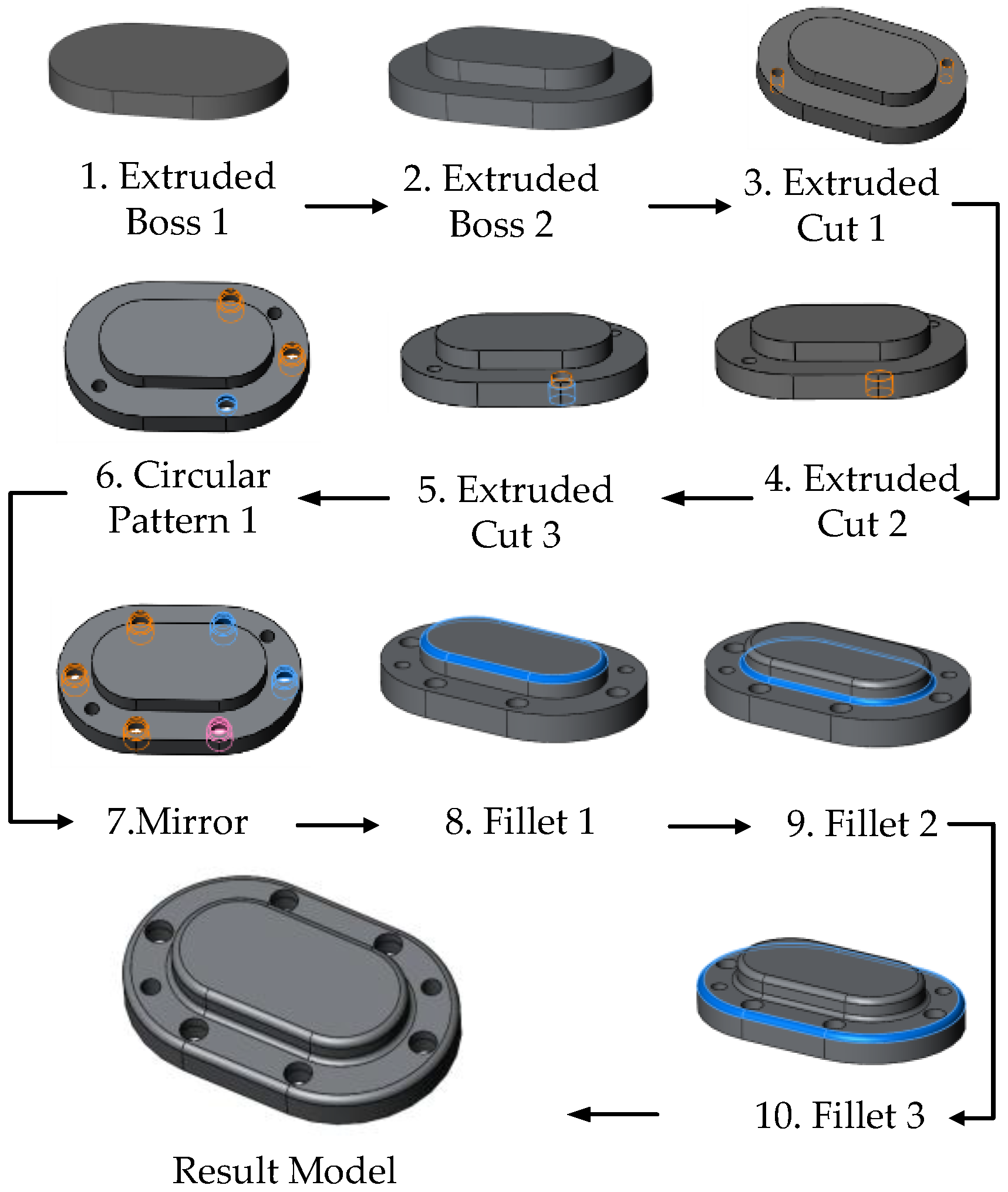
Figure 4.
Collaborative feature-dependent graph.

Figure 5.
Effect of inconsistent modeling order.

Figure 6.
Operational conflict.

Figure 7.
Overall methodology.
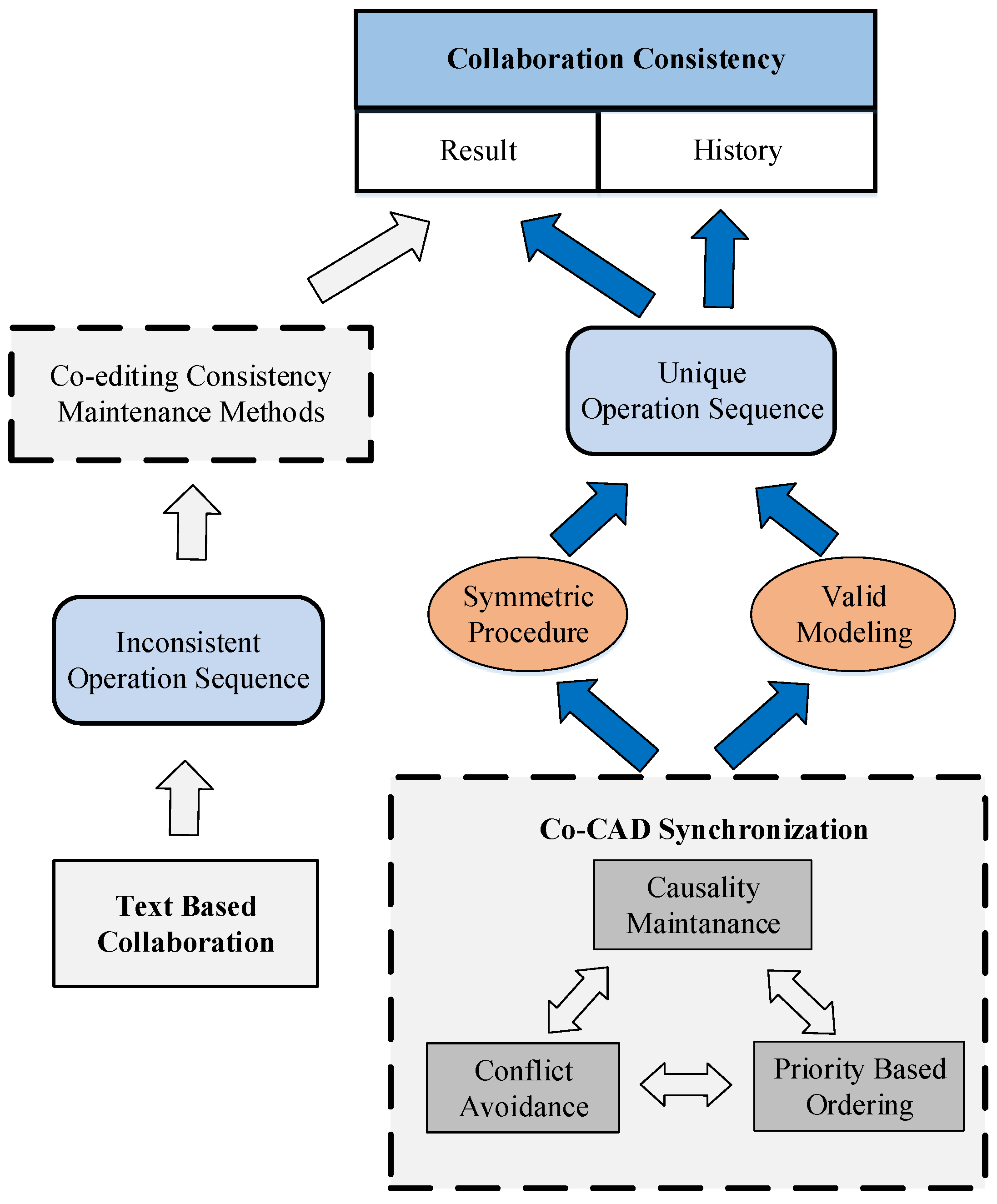
Figure 8.
Symmetric concurrency relationship control strategy.
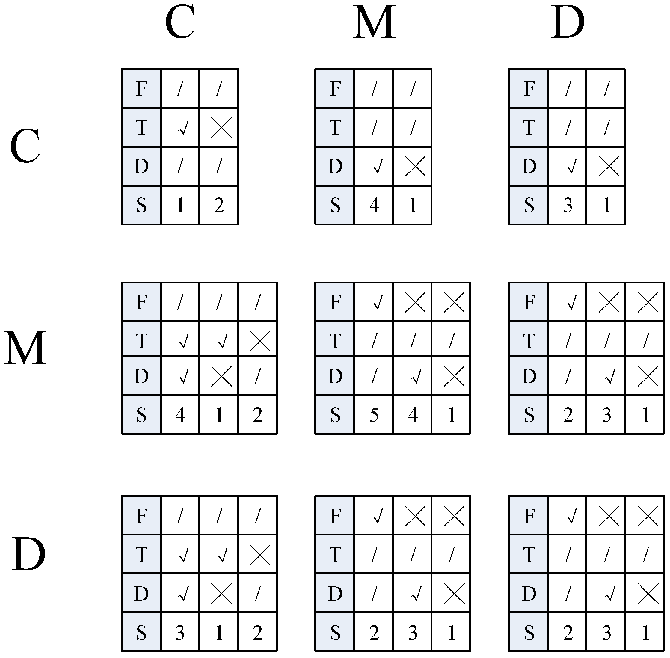
Figure 9.
Execution procedure of remote site algorithm.
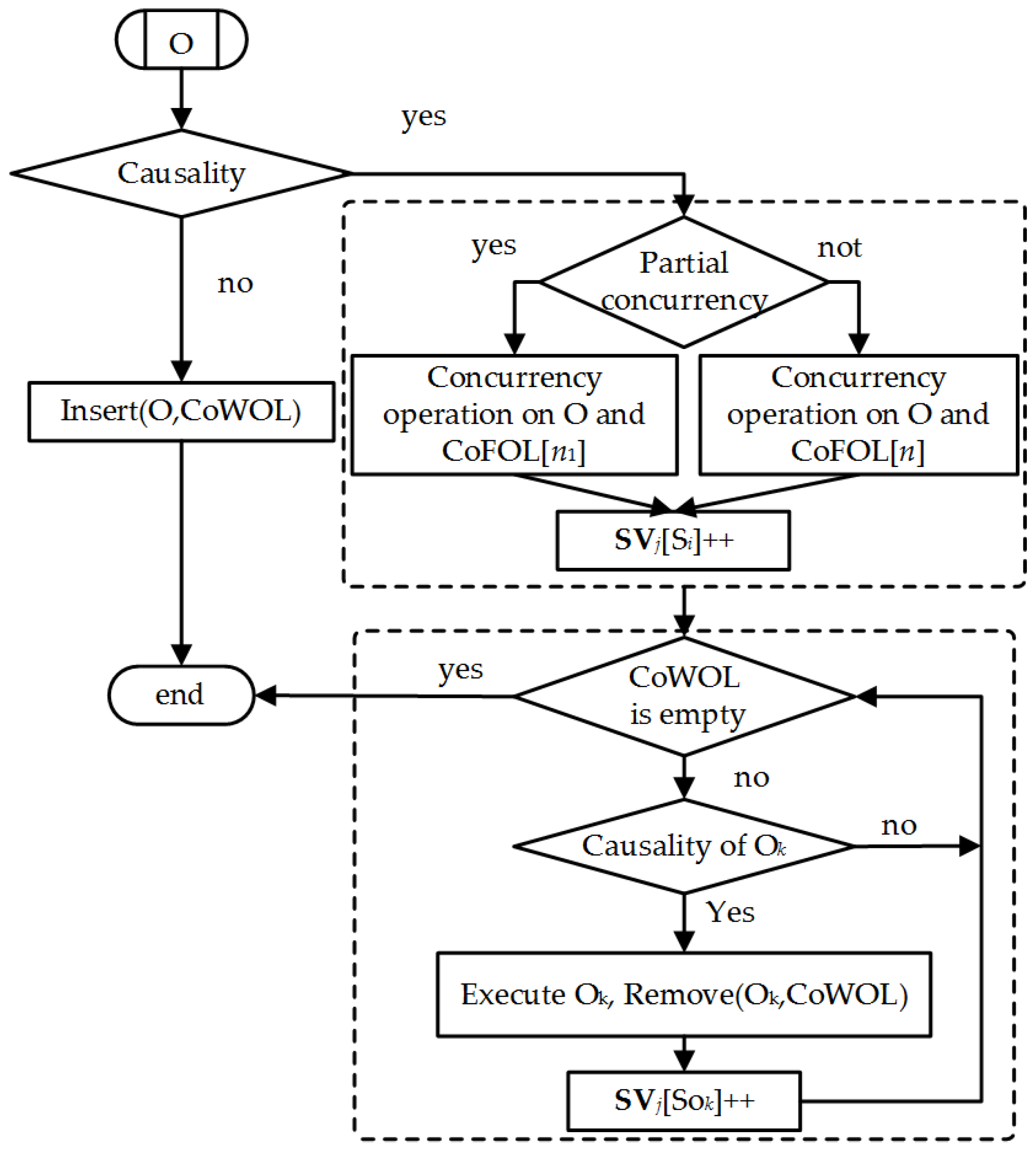
Figure 10.
Collaborative CAD modeling case study (1).
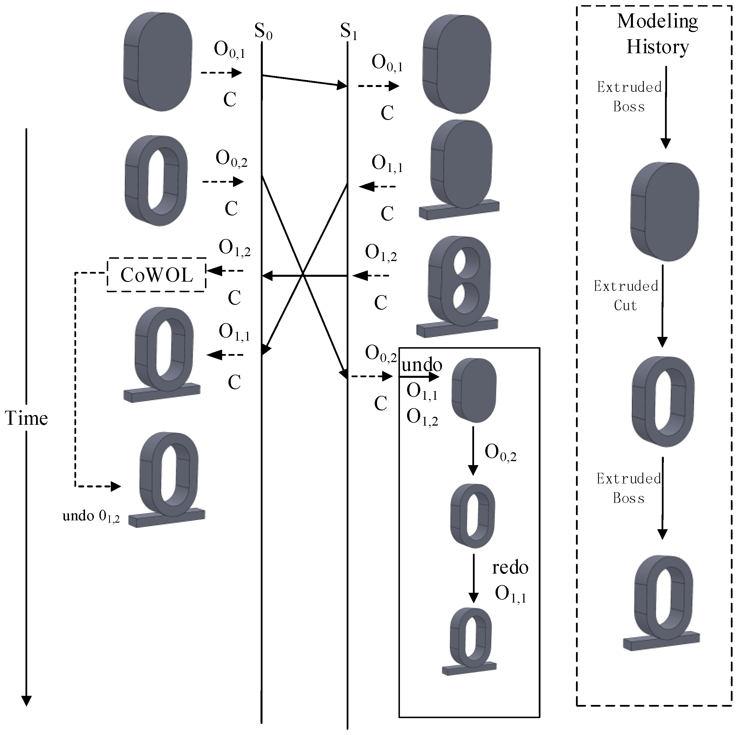
Figure 11.
Collaborative CAD modeling case study (2).
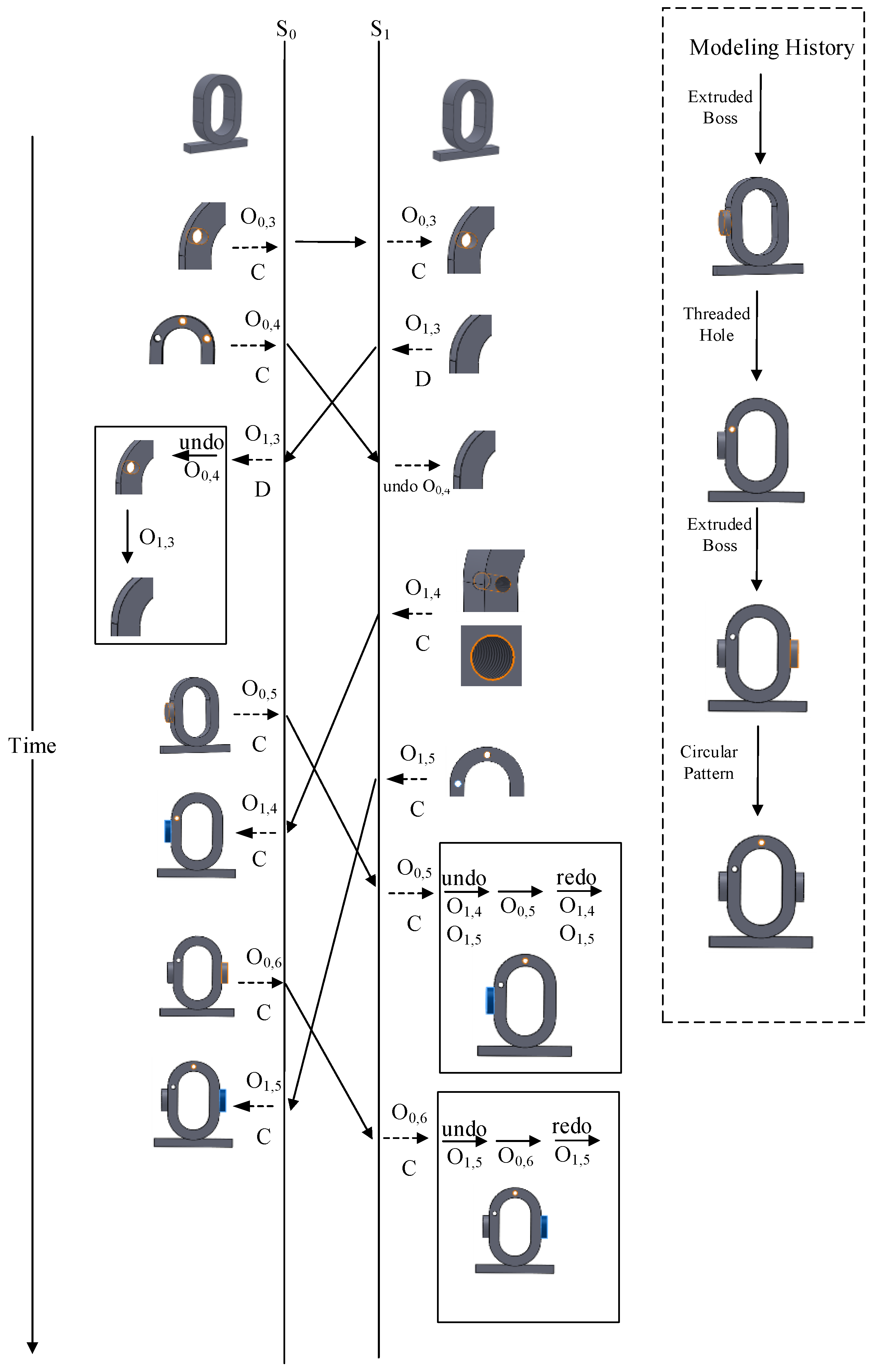
Figure 12.
Collaborative CAD modeling case study (3).

Figure 13.
Collaborative CAD modeling case study (4).
© 2017 by the authors. Licensee MDPI, Basel, Switzerland. This article is an open access article distributed under the terms and conditions of the Creative Commons Attribution (CC BY) license (http://creativecommons.org/licenses/by/4.0/).
Share and Cite
MDPI and ACS Style
Wu, Y.; He, F.; Han, S. Collaborative CAD Synchronization Based on a Symmetric and Consistent Modeling Procedure. Symmetry 2017, 9, 59. https://doi.org/10.3390/sym9040059
AMA Style
Wu Y, He F, Han S. Collaborative CAD Synchronization Based on a Symmetric and Consistent Modeling Procedure. Symmetry. 2017; 9(4):59. https://doi.org/10.3390/sym9040059
Chicago/Turabian StyleWu, Yiqi, Fazhi He, and Soonhung Han. 2017. "Collaborative CAD Synchronization Based on a Symmetric and Consistent Modeling Procedure" Symmetry 9, no. 4: 59. https://doi.org/10.3390/sym9040059
Note that from the first issue of 2016, this journal uses article numbers instead of page numbers. See further details here.