
Investigation on the Failure Mechanism of Weak Floors in Deep and High-Stress Roadway and the Corresponding Control Technology


Abstract
:1. Introduction
2. Engineering Geological Conditions
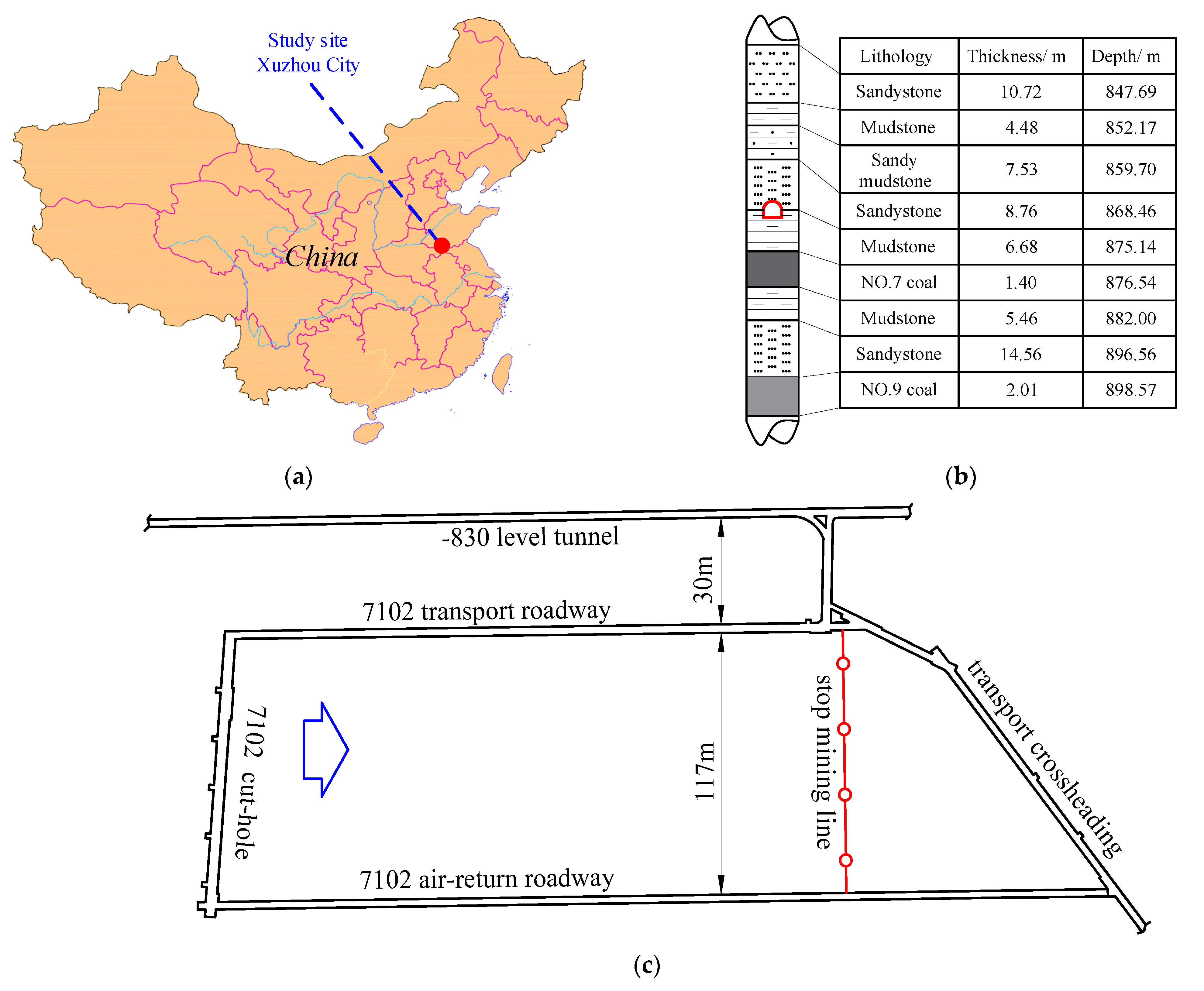
2.1. Geological Condition
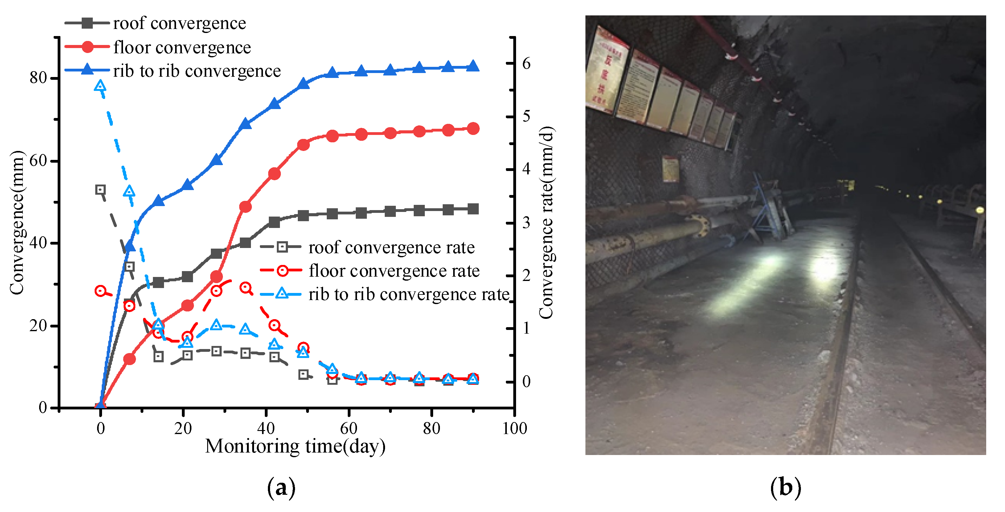
2.2. Supporting System and Deformation Characteristics
2.3. Damage Determination of the Surrounding Rock Caused by Rock Burst
3. Failure Criterion of Surrounding Rock Caused by Rock Burst
3.1. Stress Criterion
3.1.1. Static Load Analysis
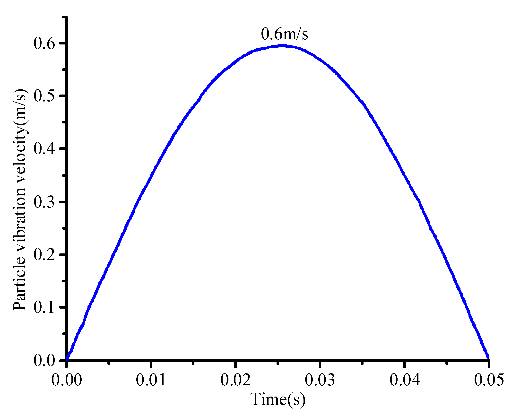
3.1.2. Dynamic Load Analysis
3.2. Energy Criterion
4. Failure Mechanism of the Surrounding Rock Caused by Rock Burst
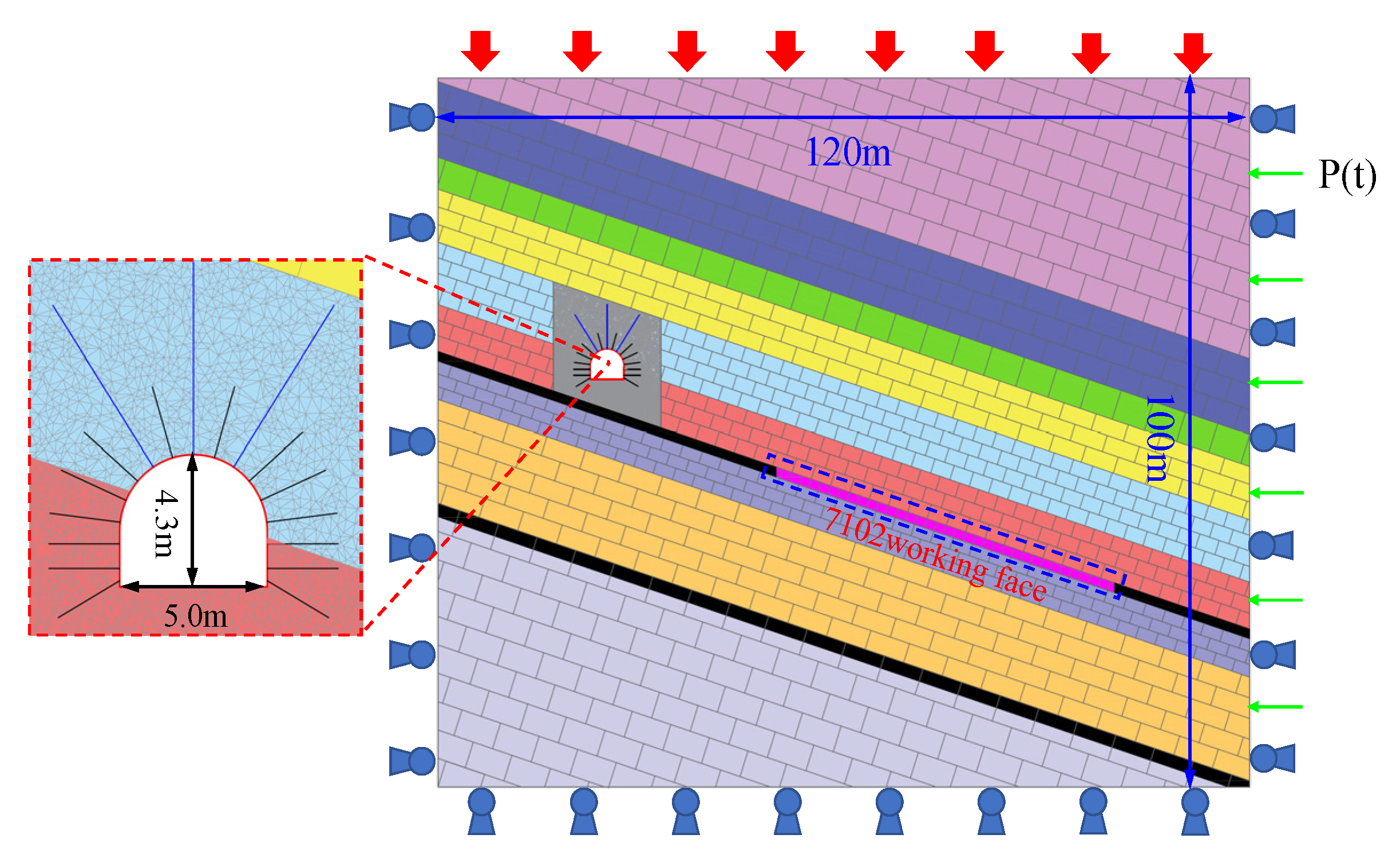
4.1. Numerical Model
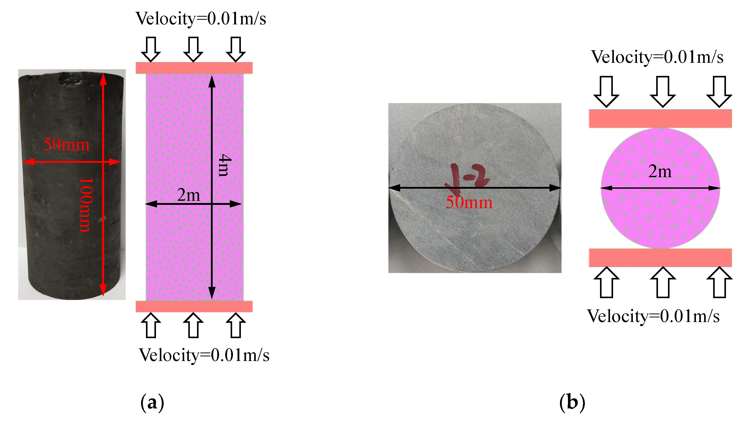
4.2. Correction of Model Parameters
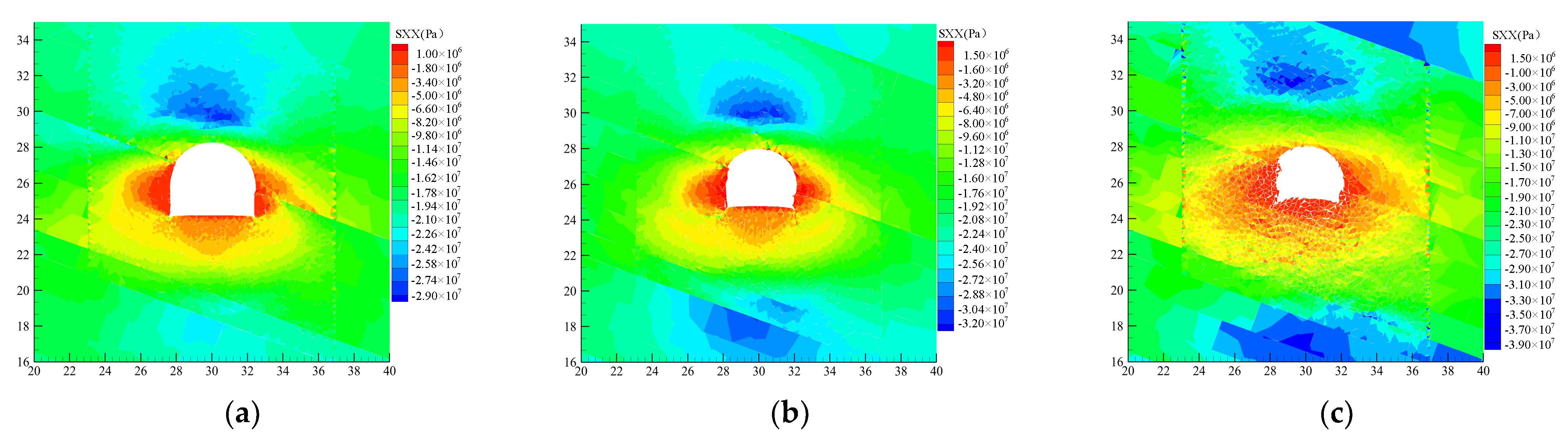
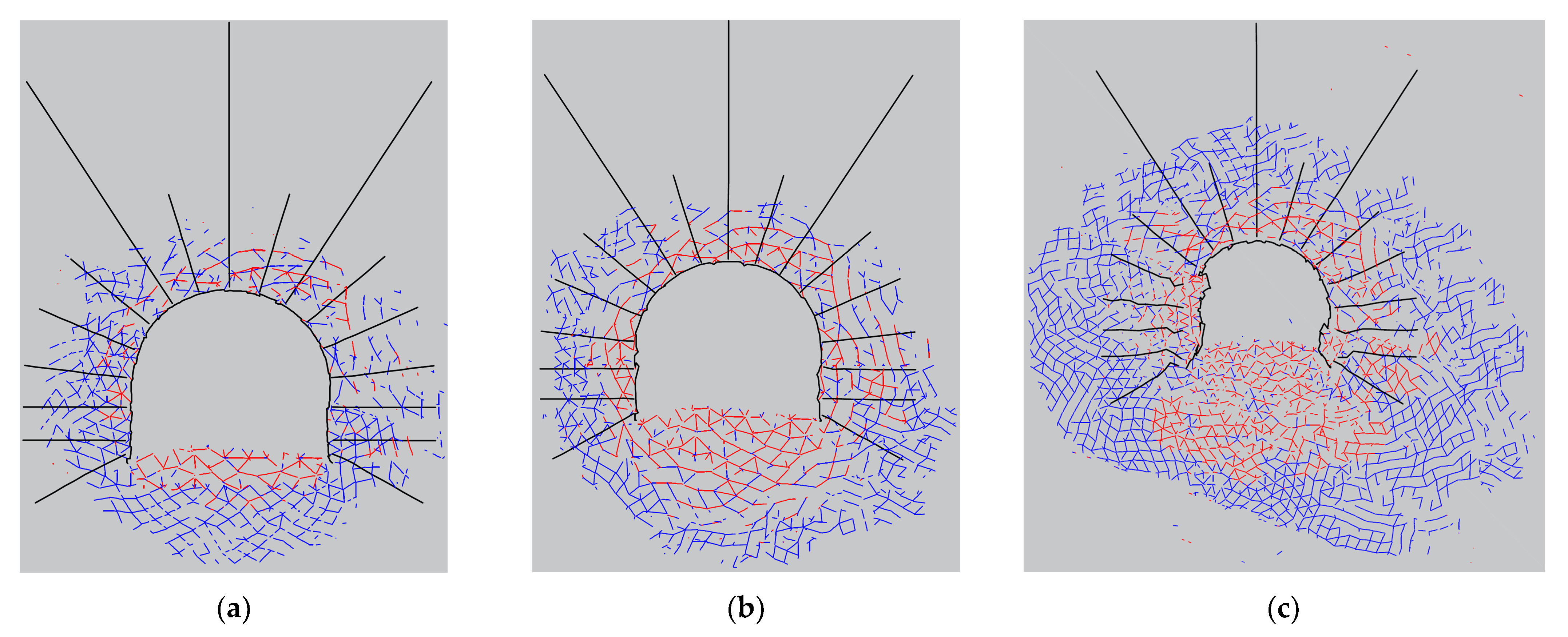
4.3. Simulation Result
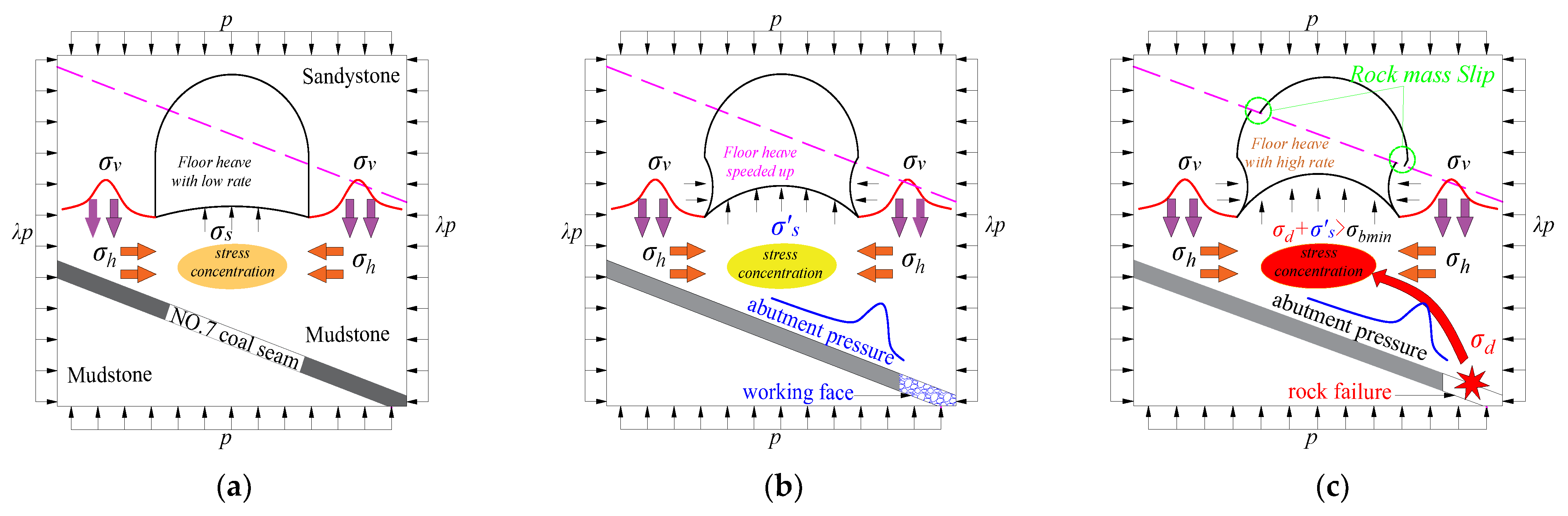
4.4. Failure Mechanism of the Roadway
5. Control Technology of Rock Burst in Roadway
5.1. Methodology
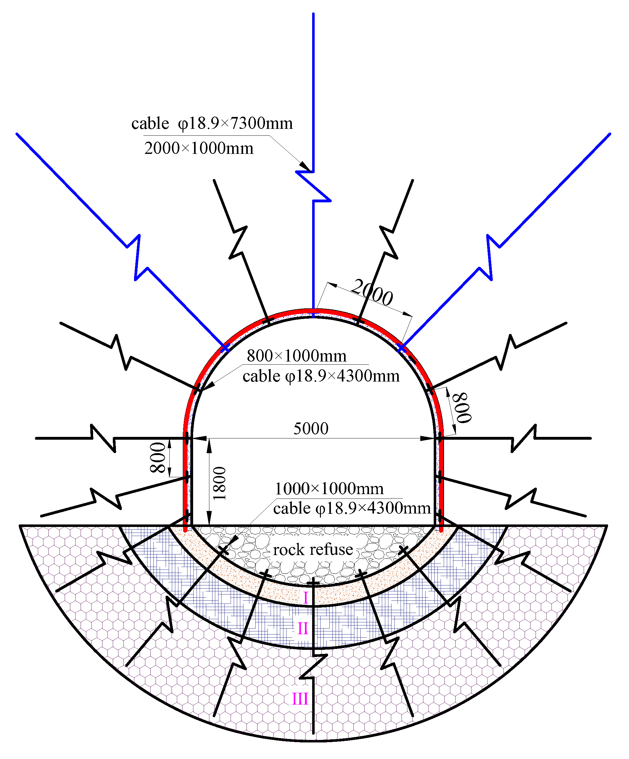
5.1.1. Full Section Anchor Cables
5.1.2. Usage of Arched Girders
5.2. Control Scheme
5.3. Engineering Application
6. Conclusions
- (1)
- The superposition of high static and strong dynamic loads, prominent differences in the strength of the surrounding rock, poor mechanical qualities of the floor, and insufficient support strength of the ribs and the floor are the main reasons for the rock burst of the floor.
- (2)
- In the environment dominated by high static load in the near field, fractures in the surrounding rock developed and strength was reduced; under the influence of the lateral stress of mining, the deformation of the surrounding rock increased; with the action of dynamic load disturbance in the far field, the impact damage on the soft rock of the roadway floor was serious.
- (3)
- This paper proposes a combined support method which include anchor cables and inverted arches. The on-site monitoring results indicate that the maximum floor heave is about 67.9 mm with the combined support technique, which is 95% lower than that under the original support conditions. The roadway floor burst was under well control.
Author Contributions
Funding
Data Availability Statement
Acknowledgments
Conflicts of Interest
References
- Wang, G.F.; Li, G.; Dou, L.M.; Mu, Z.L.; Gong, S.Y.; Cai, W. Applicability of energy-absorbing support system for rock burst prevention in underground roadways. Int. J. Rock Mech. Min. 2020, 132, 104396. [Google Scholar] [CrossRef]
- Mu, Z.L.; Liu, G.J.; Yang, J.; Zhao, Q.; Atif, J.; Gong, S.K. Theoretical and numerical investigations of floor dynamic rupture: A case study in Zhaolou Coal Mine, China. Saf. Sci. 2019, 114, 1–11. [Google Scholar] [CrossRef]
- Yuan, Y.; Liu, Z.H.; Zhu, C.; Yuan, C.F. The effect of burnt rock on inclined shaft in shallow coal seam and its control technology. Energy Sci. Eng. 2019, 7, 1882–1895. [Google Scholar] [CrossRef]
- Wu, W.D.; Bai, J.B.; Feng, G.R.; Wang, X.Y. Investigation on the mechanism and control methods for roof collapse caused by cable bolt shear rupture. Eng. Fail Anal. 2021, 130, 105724. [Google Scholar] [CrossRef]
- Qin, D.D.; Wang, X.F.; Zhang, D.S.; Chen, X.Y. Study on surrounding rock-bearing structure and associated control mechanism of deep soft rock roadway under dynamic pressure. Sustainability 2019, 11, 1892. [Google Scholar] [CrossRef] [Green Version]
- Wu, G.J.; Chen, W.Z.; Jia, S.P.; Tian, X.J.; Zheng, P.Q. Deformation characteristics of a roadway in steeply inclined formations and its improved support. Int. J. Rock Mech. Min. 2020, 130, 104324. [Google Scholar] [CrossRef]
- Lai, X.P.; Xu, H.C.; Shan, P.F.; Kang, Y.L.; Wang, Z.Y.; Wu, X. Research on mechanism and control of floor heave of mining-influenced roadway in top coal caving working face. Energies 2020, 13, 381. [Google Scholar] [CrossRef] [Green Version]
- Yang, T.; Zhang, J. Research on the treatment technology of soft rock floor heave based on a model of pressure-relief slots. Arab. J. Geosci. 2021, 14, 1278. [Google Scholar] [CrossRef]
- Shen, B.T. Coal Mine Roadway stability in soft rock: A case study. Rock Mech. Rock Eng. 2014, 47, 2225–2238. [Google Scholar] [CrossRef]
- Chang, Q.L.; Zhou, H.Q.; Xie, Z.H.; Shen, S.P. Anchoring mechanism and application of hydraulic expansion bolts used in soft rock roadway floor heave control. Int. J. Min. Sci. Tec. 2013, 23, 323–328. [Google Scholar] [CrossRef]
- Chen, Y.G.; Lu, S.L. Surrounding Rock Control of Coal Mine Roadway in China; China University of Mining & Technology Press: Xuzhou, China, 1994; pp. 463–473. [Google Scholar]
- Bi, J.B.; Li, W.F.; Wang, X.Y. Mechanism of floor heave and control technology of roadway induced by mining. J. Min. Safe Eng. 2011, 28, 1–5. (In Chinese) [Google Scholar]
- Xu, Y.; Chen, J.; Bai, J.B. Control of floor heaves with steel pile in gob-side entry retaining. Int. J. Min. Sci. Tec. 2016, 26, 527–534. [Google Scholar] [CrossRef]
- Zhao, Y.M.; Liu, N.; Zheng, X.; Zhang, N. Mechanical model for controlling floor heave in deep roadways with U-shaped steel closed support. Int. J. Min. Sci. Tec. 2015, 25, 713–720. [Google Scholar] [CrossRef]
- Guo, G.Y.; Kang, H.P.; Qian, D.Y.; Gao, F.Q.; Wang, Y. Mechanism for controlling floor heave of mining roadways using reinforcing roof and sidewalls in underground coal mine. Sustainability 2018, 10, 1413. [Google Scholar] [CrossRef] [Green Version]
- Zhang, Z.Y.; Shimada, H. Numerical study on the effectiveness of grouting reinforcement on the large heaving floor of the deep retained goaf-side gateroad: A case study in China. Energies 2018, 11, 1001. [Google Scholar] [CrossRef] [Green Version]
- Dou, L.M.; He, J.; Cao, A.Y.; Gong, S.Y.; Xai, W. Rock burst prevention methods based on theory of dynamic and static combined load induced in coal mine. J. Chin. Coal Soc. 2015, 40, 1469–1476. (In Chinese) [Google Scholar]
- He, J.; Dou, L.M.; Gong, S.Y.; Li, J.; Ma, Z.Q. Rock burst assessment and prediction by dynamic and static Stress analysis based on micro-seismic monitoring. Int. J. Rock Mech. Min. 2017, 93, 46–53. [Google Scholar] [CrossRef]
- He, M.C.; Ren, F.Q.; Liu, D.Q. Rockburst mechanism research and its control. Int. J. Min. Sci. Tec. 2018, 28, 829–837. [Google Scholar] [CrossRef]
- Cao, A.Y.; Zhu, L.L.; Du, Z.Y.; Liu, J.G.; Wang, H.; Wang, Y. Control principle and pressure-relief technique of rock burst occurred in roadway floor. J. Min. Safe Eng. 2013, 30, 251–255. (In Chinese) [Google Scholar]
- Gao, M.S.; He, Y.L.; Xu, D.; Yu, X. A new theoretical model of rock burst-prone roadway support and its application. Geofluids 2021, 2021, 5549875. [Google Scholar] [CrossRef]
- Kang, H.P.; Jiang, P.F.; Wu, Y.Z.; Gao, F.Q. A combined “ground support-rock modification-destressing” strategy for 1000-m deep roadways in extreme squeezing ground condition. Int. J. Rock Mech. Min. 2021, 142, 104746. [Google Scholar] [CrossRef]
- Xiao, H.B. Control technology of mine pressure bump occurred by floor dynamic loading in rise gateways of deep mine. Coal Sci. Tech. 2017, 45, 39–44. (In Chinese) [Google Scholar]
- Yang, Y.S.; Wei, S.J.; Li, K. Inverse analysis of dynamic failure characteristics of roadway surrounding rock under rock burst. Energy Sci. Eng. 2021, 9, 2298–2310. [Google Scholar] [CrossRef]
- Li, J.Z.; Guo, P.H.; Cui, H.; Song, S.K.; Zhao, W.T.; Chu, J.Q.; Xie, W.H. Dynamic response mechanism of impact instability induced by dynamic load disturbance to surrounding rock in high static loading roadway. Minerals 2021, 11, 971. [Google Scholar] [CrossRef]
- Kong, P.; Jiang, L.S.; Jiang, J.Q.; Wu, Y.Z.; Chen, L.J.; Ning, J.G. Numerical Analysis of roadway rock-burst hazard under superposed dynamic and static loads. Energies 2019, 12, 3761. [Google Scholar] [CrossRef] [Green Version]
- Liu, C.W. Spatial Strata Stress Field Evolution Regularity Induced by Mining Engineering and Simulation; Yellow River Water Conservancy Press: Zhengzhou, China, 2005; pp. 124–126. [Google Scholar]
- Guo, X.F.; Zhao, Z.Q.; Gao, X.; Wu, X.Y.; Ma, N.J. Analytical solutions for characteristic radii of circular roadway surrounding rock plastic zone and their application. Int. J. Min. Sci. Tec. 2019, 29, 263–272. [Google Scholar] [CrossRef]
- Cao, A.Y.; Fan, J.; Mu, Z.L.; Guo, X.Q. Burst failure effect of mining-induced tremor on roadway surrounding rock. J. Chin. Coal Soc. 2010, 35, 2006–2016. (In Chinese) [Google Scholar]
- Gao, M.S.; Dou, L.M.; Xie, Y.S.; Gao, J.; Zhang, L.S.; Yang, Z. Latest progress on study of stability control of roadway surrounding rocks subjected to rock burst. Procedia Earth Planet. Sci. 2009, 1, 409–413. [Google Scholar] [CrossRef] [Green Version]
- Wen, W.D.; Bai, J.B.; Wang, X.Y.; Yan, S. Numerical study of failure mechanisms and control techniques for a gob-side yield pillar in the Sijiazhuang coal mine, China. Rock Mech. Rock. Eng. 2019, 52, 1231–1245. [Google Scholar] [CrossRef]
- Kazerani, T.; Zhao, J. Micromechanical parameters in bonded particle method for modelling of brittle material failure. Int. J. Numer. Anal. Meth. Geomech. 2010, 34, 1877–1895. [Google Scholar] [CrossRef]
- Yang, B.J. Elastic Wave Theory; Northeast Normal University Press: Changchun, China, 1990; pp. 136–148. [Google Scholar]
- Lu, C.P. Intensity Weakening Theory for Rockburst of Compound Coal-Rock and Its Application. Ph.D. Thesis, China University of Mining and Technology, Xuzhou, China, 2008. [Google Scholar]
- Wang, X.; Cai, M. Numerical modeling of seismic wave propagation and ground motion in underground mines. Tunn. Undergr. Space Technol. 2017, 68, 211–230. [Google Scholar] [CrossRef]
- Li, Y.C.; Sun, S.Y.; Tang, C.A. Analytical prediction of the shear behaviour of rock joints with quantified waviness and unevenness through wavelet analysis. Rock Mech. Rock Eng. 2019, 52, 3645–3657. [Google Scholar] [CrossRef]
- Wu, S.; Wu, Z.; Zhang, C. Rock burst prediction probability model based on case analysis. Tunn. Undergr. Space Technol. 2019, 93, 103069. [Google Scholar] [CrossRef]
- Zhang, L.; Einstein, H.H. Using RQD to estimate the deformation modulus of rock masses. Int. J. Rock Mech. Min. 2004, 41, 337–341. [Google Scholar] [CrossRef]
- Singh, M.; Rao, K.S. Empirical methods to estimate the strength of jointed rock masse. Eng. Geol. 2005, 77, 127–137. [Google Scholar] [CrossRef]
- Gao, F.Q.; Stead, D.; Kang, H.P. Numerical simulation of squeezing failure in a coal mine roadway due to mining-induced stresses. Rock Mech. Rock Eng. 2015, 48, 1635–1645. [Google Scholar] [CrossRef]
- Wu, B.W.; Wang, X.Y.; Bai, J.B.; Wu, W.D.; Zhu, X.X.; Li, G.D. Study on Crack Evolution Mechanism of Roadside Backfill Body in gob-side entry retaining based on UDEC trigon model. Rock Mech. Rock Eng. 2019, 52, 3385–3399. [Google Scholar] [CrossRef]
- Liu, S.G.; Bai, J.B.; Wang, X.Y.; Wu, B.W.; Wang, G.H.; Li, Y.H.; Xu, J. Study on dynamic evolution of roof crack and support timing of secondary tunneling for large section open-off cut in deep mines. Adv. Civ. Eng. 2021, 2021, 9918470. [Google Scholar] [CrossRef]
- Wu, B.W.; Wang, X.Y.; Bai, J.B.; Liu, S.G.; Wang, G.H.; Li, G.J. A study of the anchorage body fracture evolution and the energy dissipation rule: Comparison between tensioned rock bolts and torqued rock bolts. Adv. Civ. Eng. 2021, 2021, 5542569. [Google Scholar] [CrossRef]


| Support Elements | Contact Properties | Value |
|---|---|---|
| Cable | Cohesive strength of shear coupling spring (MPa) | 1.2 |
| Stiffness of shear coupling spring (GPa) | 8.4 | |
| Frictional resistance of the shear coupling spring (°) | 8.3 | |
| Cohesive strength of normal coupling spring (MPa) | 215 | |
| Tensile yield strength (kN) | 460 | |
| Stiffness of normal coupling spring (GPa) | 21 | |
| Bolt | Cross-sectional area(m2) | 3.8 × 10⁻⁴ |
| Elastic modulus (GPa) | 200 | |
| Tensile yield strength (kN) | 198 | |
| Structure | Elastic modulus (GPa) | 200 |
| Tensile yield strength (MPa) | 500 | |
| Compressive yield strength (MPa) | 500 | |
| Interface normal stiffness (GPa/m) | 10 | |
| Interface shear stiffness (GPa/m) | 10 |
| PPV/m/s | Depth of the Roadway (H)/m |
|---|---|
| PPV ≤ 0.05 | H ≤ 300 |
| 0.05 < PPV ≤ 0.20 | 300 < H ≤ 500 |
| 0.20 ≤ PPV ≤ 0.40 | 500 < H ≤ 700 |
| PPV > 0.40 | H > 700 |
| Rock Strata | Intact Rock | RQD | Rock Mass | |||
|---|---|---|---|---|---|---|
| Er/GPa | σc/MPa | Em/GPa | σcm/MPa | σtm/MPa | ||
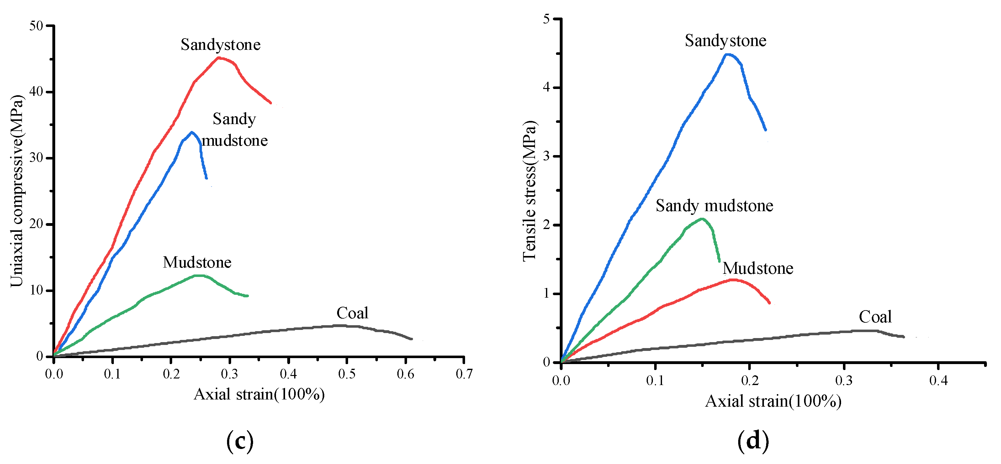
| Sandstone | 22.1 | 56.3 | 93 | 14.6 | 45.1 | 4.51 |
| Mudstone | 9.2 | 25.8 | 78 | 3.2 | 12.3 | 1.23 |
| Sandy mudstone | 14.1 | 36.4 | 85 | 6.6 | 21.4 | 2.14 |
| No. 7 coal seam | 3.2 | 12.2 | 70 | 0.8 | 4.62 | 0.46 |
| Rock Strata | Rock Mass Properties | Contact Surface Parameters | ||||||
|---|---|---|---|---|---|---|---|---|
| Dens/kg/m3 | Bulk/GPa | Shear/GPa | Jkn/GPa·m−1 | Jks/ GPa·m−1 | Jcoh/MPa | Jfric/° | Jtens/MPa | |
| Sandstone | 2 600 | 10.15 | 5.80 | 23.6 | 4.72 | 2.7 | 32/24 | 2.1 |
| Mudstone | 2 100 | 2.07 | 1.30 | 14.2 | 2.84 | 1.2 | 28/20 | 0.9 |
| Sandy mudstone | 2 350 | 4.79 | 2.60 | 18.5 | 3.70 | 1.6 | 23/18 | 0.6 |
| No. 7 coal seam | 1 300 | 0.53 | 0.32 | 6.1 | 1.22 | 0.9 | 21/15 | 0.2 |
| Rock Strata | E/GPa | Error/ 100% | UCS/MPa | Error/ 100% | BTS/MPa | Error/ 100% | |||
|---|---|---|---|---|---|---|---|---|---|
| Target | Calibrated | Target | Calibrated | Target | Calibrated | ||||
| Sandstone | 14.60 | 14.49 | −0.75 | 45.1 | 45.8 | 1.55 | 4.51 | 4.64 | 2.80 |
| Mudstone | 3.20 | 3.14 | −1.88 | 12.3 | 12.4 | 0.08 | 1.23 | 1.18 | −4.07 |
| Sandy mudstone | 6.60 | 6.72 | 1.81 | 21.4 | 20.8 | −2.80 | 2.14 | 2.10 | −1.86 |
| No. 7 coal seam | 0.80 | 0.75 | −6.25 | 4.62 | 4.60 | −0.04 | 0.46 | 0.49 | 6.52 |
Publisher’s Note: MDPI stays neutral with regard to jurisdictional claims in published maps and institutional affiliations. |
© 2021 by the authors. Licensee MDPI, Basel, Switzerland. This article is an open access article distributed under the terms and conditions of the Creative Commons Attribution (CC BY) license (https://creativecommons.org/licenses/by/4.0/).
Share and Cite
Zhang, D.; Bai, J.; Yan, S.; Wang, R.; Meng, N.; Wang, G. Investigation on the Failure Mechanism of Weak Floors in Deep and High-Stress Roadway and the Corresponding Control Technology. Minerals 2021, 11, 1408. https://doi.org/10.3390/min11121408
Zhang D, Bai J, Yan S, Wang R, Meng N, Wang G. Investigation on the Failure Mechanism of Weak Floors in Deep and High-Stress Roadway and the Corresponding Control Technology. Minerals. 2021; 11(12):1408. https://doi.org/10.3390/min11121408
Chicago/Turabian StyleZhang, Dong, Jianbiao Bai, Shuai Yan, Rui Wang, Ningkang Meng, and Gongyuan Wang. 2021. "Investigation on the Failure Mechanism of Weak Floors in Deep and High-Stress Roadway and the Corresponding Control Technology" Minerals 11, no. 12: 1408. https://doi.org/10.3390/min11121408