
A Review on Froth Washing in Flotation


Institute for the Development of Energy for African Sustainability, University of South Africa, Florida P.O. Box 392, South Africa
*
Author to whom correspondence should be addressed.
Minerals 2022, 12(11), 1462; https://doi.org/10.3390/min12111462
Submission received: 12 August 2022
/
Revised: 1 November 2022
/
Accepted: 14 November 2022
/
Published: 19 November 2022
(This article belongs to the Section Mineral Processing and Extractive Metallurgy)
Abstract
:In the attempt to process lower-grade ores, mineral flotation has taken centre stage as the preferred recovery route. However, in many instances, the froth product does not have a high grade due to the entrainment of gangue minerals. Industry has solved this challenge by introducing froth washing mechanisms. Clean wash water is introduced into or on top of the froth to reduce the amount of entrained gangue in the final concentrate. This article reviews froth-washing systems in detail and highlights the advantages and disadvantages of each wash-water delivery mechanism. Comments on industrial uptake are provided. The indications are that froth washing improves the grade of the concentrate and influences froth stability and mobility. Other researchers have reported an improvement in recovery—especially of coarse particles—with wash water being added, while others have reported a reduction in recovery, especially with composite particles. Froth washing is generally applied in mechanical flotation cells by washing at the lip. In column flotation cells and Jameson cells, wash water is added to the entire froth surface. The literature also indicates that the wash-water rate, wash-water quality, type of wash-water delivery/ distribution mechanism and the area covered by wash water are critical parameters that dictate the efficacy of the washing system. Further research is necessary on the impact of wash-water quality on the froth phase sub-processes including froth rheology.
1. Introduction
Froth flotation is a mineral processing technique that is popular when processing low-grade ores. It involves introducing chemically treated, finely ground ore in the form of a slurry into a flotation cell where air is also added in the form of bubbles. The chemicals added to the slurry manipulate the surface of valuable minerals by rendering them hydrophobic, while gangue particles remain hydrophilic or vice versa in reverse flotation where the gangue is floated and the valuable mineral is rendered hydrophilic [1]. In the pulp phase of the flotation cell, air in the form of bubbles of a specific size pick up the hydrophobic particles and rise to the top, where they form a froth that increases in height as more bubbles impinge at the bottom; it eventually overflows the concentrate weir and is collected in launders.
The performance of the froth phase is governed by sub-processes, namely liquid drainage, particle detachment or attachment, and bubble coalescence and break-up. These sub-processes dictate froth recovery and grade, which are typically used as performance measures of the froth [2]. Froth recovery is defined as the fraction of particles that enter the froth phase, survive its cleaning action and are recovered as the concentrate [3]. Grade refers to the content of the marketable product in the concentrate expressed as a percentage of the total concentrate [3]. The grade of the concentrate is lowered by entrainment, which is a non-selective process responsible for carrying fine particles from the pulp into the froth. Particles are entrained into the froth by the liquid that is pushed into the froth in the bubble wake or by mechanical means through turbulence and slime coatings [4,5]. Mechanisms to explain entrainment that have been established in the literature include: the Moys [6] theory that states that unattached particles are carried upwards in bubble lamella; the Yianatos et al. [7] model that indicates that particles are transported to the froth in the wake of ascending air bubbles. Smith and Warren [8] used the bubble swarm theory to suggest that water in the pulp phase is mechanically pushed into the froth phase by a rising swarm of bubbles. The water carries with it fine particles, the bulk of which are gangue minerals, because there is a high concentration in the pulp. Gangue minerals can also be recovered through entrapment [9].
Several methods have been developed to reduce the impact of entrainment in the froth. Broadly speaking, these can be categorised into operational, physical methods and chemical methods. This review will focus on the physical froth-flow modifiers and operational methods, which include the three methods detailed below.
1.1. Methods That Alter Froth Residence Time
These methods include changing the froth depth, changing the gas rate and the use of physical froth-flow modifiers. These methods alter the mean froth residence time. Changing froth-retention time changes the froth recovery and water recovery and allows for entrained particles to drain back into the pulp. For example: changing the froth depth changes the water recovery across the froth. This is because changing the froth depth changes the froth residence time and subsequently lead to a decrease or increase in water and solids drainage [10,11,12,13,14,15,16,17,18]. Changing the gas rate also alters the water recovery across the froth. For instance, increasing the gas rate increases the entrainment recovery as a result of the associated increase in froth rising velocity and the corresponding decrease in average froth-retention time [11,15,17,18,19,20]. Inserting froth-flow modifiers, e.g., baffles, crowders, launders and paddles, also changes the froth-retention time, and can therefore impact the entrainment recovery. The work on froth baffles conducted by Moys [6] and Bhondayi [21] showed that the froth residence time could be altered and allow for more drainage time of the entrained gangue particles in the froth, especially near the concentrate weir.
1.2. Methods That Reduce Turbulence in the Pulp
These methods include increasing the quiescent zone, reducing the impeller speed and using horizontal baffles. A quiescent zone is a region found above the turbulent zone in the pulp zone [22]. This region has less turbulence, which helps to reduce the probability of gangue mineral recovery by mechanical entrainment [22,23,24]. Schubert [23] showed that mechanical and hydraulic entrainments decrease when the turbulence in the quiescent zone is reduced. Razmjooei et al. [24] reported that reducing the impeller speed reduces turbulence and the mean velocity in the quiescent zone, which leads to a reduction in the number of solid particles (less than 50 µm) available for entrainment. Inserting a horizontal froth baffle lowers entrainment, as alluded to by Kawatra and Eisele [25], who observed a significant increase in concentrate grade and a reduction in churn in the presence of retrofitted horizontal baffles. Cilek [26] reported that impellor speeds can be regulated to lower the degree of entrainment in the froth.
1.3. Froth Washing
This is another method that can be used to “clean” the froth off entrained particles. Froth washing is effective in reducing the number of entrained particles in the froth [27,28,29,30,31,32,33]. The process of froth washing involves spraying water onto the froth. The added water helps the drainage of the entrained/loosely held particles back into the pulp phase by displacing the entrained liquid that transmits gangue particles. Froth washing increases grade, flotation recovery, froth stability and mobility, and thus enhances the performance of a flotation cell [28]. Despite the success achieved with froth washing, especially in column flotation cells, the Jameson cell (particularly in the coal processing industry), there are factors that lead to sub-optimal performance if they are not optimised. These include wash-water flowrate [27,28,34,35]; wash-water quality [27,28,29,30,31,32,33]; type and mechanism of wash-water delivery/distribution [28,29,30,32,33,36,37,38,39,40]; area covered by wash water [27,28,29,30,41,42]. Maldistribution of wash water [28,42,43] affects the degree of froth mixing, causes channeling and short-circuiting in froth [44], and can result in suboptimal metallurgical performance of a flotation cell. An excessive number of fine particles in the pulp may increases entrainment, and froth washing has been used to counter this extra entrainment [5,27,28,29,30,31,32,33].
The purpose of this review is to discuss froth washing in detail. It details how wash water reduces the number of entrained particles in the froth, and how this impacts flotation performance in terms of recovery and grade. The available froth-washing mechanisms are discussed, including the advantages and disadvantages of each mechanism. This review is important as it will add knowledge on froth washing, which is a widely used process for froth cleaning in flotation.
2. Froth Phase Sub-Processes
In froth flotation, the particles of interest are physically separated from the gangue minerals by taking advantage of their ability to adhere to the surface of bubbles, due to particle surface hydrophobicity. The hydrophobic particles attach to the air bubbles and are carried to the surface, where they form a froth, while hydrophilic particles remain in the pulp to be drained as tails [45]. Initially, the loaded bubbles entering the froth are mostly spherical, with a liquid film surrounding them. However, as more bubbles impinge at the base of the froth, the layer of froth increases in height and slurry drains back into the froth. The liquid around the bubbles (bubble lamella) drains and becomes increasingly thinner, which encourages bubble coalescence. The bubbles thus become larger and polyhedral in shape, with plateau borders forming at the junction of three bubbles [46], i.e., tubular conduits in which water and detached particles flow. Detached particles may reattach to the available surface of rising bubbles or drop and drain back to the pulp phase. Thus, the froth phase sub-processes, bubble coalescence, particle detachment and reattachment, and froth drainage significantly influence the overall grade and recovery of the froth [1,47]. Froth phase sub-processes dictate the type and composition of particles in the lamella and plateau borders at any given time [46]. When two bubbles collide and merge, oscillations due to this collision result in the loss of particles [48,49,50]. Therefore, coalescence results in the detachment of particles. The detached particles can reattach to the rising bubbles via a selective process, based on hydrophobicity and particle size [1,6,51], which influences overall flotation performance.
2.1. Brief Overview of Froth Behavior
The major function of the froth is to transport the valuable minerals to the concentrate weir or froth discharge launders. Therefore, the froth should be able to resist bubble coalescence and bursting events, a property that is defined as froth stability. Several factors influence froth stability, including particle size and hydrophobicity [2,52], quality of process water, gas dispersion characteristics, particle contact angle, temperature, salt concentration, etc. [53]. Farrokhpay [53] reported that froth stability plays an important role in determining grade and mineral recovery. The froth should be stable enough to allow drainage of gangue particles and recovery of mineral values. A froth that is too stable is difficult to manage and leads to difficulties in mineral recovery because it has a high mineral content, which retards drainage of hydrophobic particles to the launder [54]. If the froth is unstable (i.e., breaks continuously as the liquid drains from between bubbles) [54], it results in low recovery because mineral-laden bubbles collapse before they are transported over the concentrate weir. Unstable froths are runny and consist of loosely packed spherical bubbles with little valuable minerals. A very stable froth i.e., metastable froth is sticky with a high froth load due to closely packed ellipsoidal bubbles. Very stable froths are too viscous and have large bubbles entraining a large number of gangue minerals, which consequently leads to a poor grade of concentrate [54].
Very stable froths become dry in the upper layers [55,56] as a result of particles dropping back and liquid drainage. Wash water sprayed compensates for the water lost in the upper layers of the froth preventing bubbles from bursting events, thus increasing froth stability and improving the recovery of particles [28,55,56].
In addition to being of acceptable stability, the froth should also be mobile, in order for it to flow to the concentrate launder. A froth property called froth mobility refers to the flow streamlines that occur in the froth between the pulp-froth interface and the froth discharge [57,58]. Froth mobility has been linked to the froth structure. Moolman et al. [54] stated that large elliptical bubbles with high froth loading are a result of an excessively stable, sticky froth. The characteristics of a sticky froth are high viscosity with lower mobility compared to that of an ideal froth. A runny froth is too watery, has low mineralisation and is excessively mobile [54]. An ideal froth is not too runny or too viscous.
Froth rheology is an important froth property in flotation because it has the possibility of affecting both froth mobility and froth stability [59]. One of the terms associated with froth rheology is viscosity. Experienced plant operators have often used their fingers to test whether the froth is viscous so that operating variables can be adjusted promptly. Shi and Zheng [59] reported that the froth becomes drier and more viscous when it stays longer in the flotation cell on its way to the launders. This can only be attributed to water draining from the froth. As a result, water and entrained particles per unit volume of froth decrease. In the process, froth mobility is lowered. Froth washing has the benefit of compensating for the water lost in the upper layers of the froth, which improves froth mobility, stability and recovery [28,55,56]. Therefore, froth washing influences froth rheology. Shi and Zheng [59] reported that the froth becomes less viscous as the water hold-up in the froth increases. No other research has been conducted on the impact of froth washing on froth rheology. Kaya [28] reported that wash water reduces bubble coalescence, which leads to improved recovery in flotation. After introducing wash water, the bubble lamella thickens. The number of large particles held in the froth increases. In addition, the amount of water draining from the froth also increases and effectively “washes’ down entrained particles; this is effectively a secondary concentration process which leads to an improved froth grade. The increase in the recovery of coarse particles and the secondary concentration process results in an increase in recovery and grade [28].
2.2. Transporting Gangue Minerals into the Froth
Three main mechanisms have been identified as being responsible for transporting gangue minerals into the froth and these are entrainment, recovery as composite particles using their hydrophobic portion attached to bubbles and entrapment by aggregates attached to bubbles [8]. Entrainment is known to be the biggest contributor to recovering gangue minerals in the froth [8,9,12,60,61,62,63,64,65,66]. It is a process that transfers fine particles into the froth through mechanical means [67,68]. The process is non-selective; therefore, fine particles of both valuable minerals and gangue minerals are transported into the froth. However, because gangue minerals are typically abundant compared to valuable minerals, a reduction in concentrate grade is observed. Therefore, entrainment must be managed actively.
Entrainment is known to take place in two steps. Step 1 involves moving particles from the top of the pulp, across the pulp-froth interface and into the froth. Step 2 involves transferring these particles from the froth phase to the concentrate [63,64,66]. Generally, three mechanisms are considered responsible for Step 1. These are: (i) unattached particles being carried upwards in bubble lamella, which is known as the boundary layer theory [6,9,17,60,61]; (ii) the bubble swarm theory [8,65], which posits that swarms of bubbles below the pulp-froth interface mechanically push water and suspended particles across the pulp-froth interface; (iii) the bubble wake theory [17,62], which posits that the bubble wake transfers particles into the froth. Water in bubble lamella, or in the wake of a bubble or water being mechanically pushed by swarms of bubbles is central to explaining entrainment. Thus, several relationships between water recovery and particle recovery by entrainment have been suggested, including the dominant linear relationship, as observed by several researchers [4,6,8,11,15,17,38,56,69,70,71,72,73].
Another mechanism for transporting gangue into the froth was suggested by Gaudin [9] as reported by Smith and Warren [8], i.e., entrapment. Entrapment takes place when non-floatable particles (gangue minerals) are trapped between valuable particles that are attached to adjoining/clustered bubbles and which are recovered to the froth product [9,28]. This lowers the grade of the froth. Zheng et al. [15] further reported that entrapment occurs when the thickness of the froth lamellae and plateau borders reduces to a value similar to or less than the particle size, hindering the free drainage of particles. Zheng et al. [15] further stated that entrapment can be responsible for the disproportionately higher recovery of larger particles of gangue minerals relative to fine particles. Kaya [28] further reported that entrapment becomes more dominant with low water recovery or when the froth becomes dry. Introducing froth washing was found to reduce entrapment.
2.3. Managing Entrainment Recovery
Several factors are known to influence entrainment, including feed properties, mainly particle size and density [8,17,74,75,76,77]; operational parameters, such as pulp density [15,77], impeller speed [17,78], gas rate [15,17] and froth height [6,10,11,13,14,15,16,17]. Controlling and manipulating these factors is one way of managing entrainment. Fundamentally, the reduction in particles recovered by entrainment targets the two-step process that results in the entrainment of particles. For instance, Zheng et al. [15] observed that the degree of entrainment increases with an increase in the air rate and decreases with an increase in the froth height. An increase in air rate leads to an increase in the rising velocity of the froth and shortens froth-retention time. Therefore, a lower proportion of particles per unit mass of water drains back into the pulp from the froth phase. Increasing the froth height prolongs the froth-retention time, which allows more water and unwanted fine particles to drop back into the pulp. This produces a cleaner froth [15]. In this case, manipulating the gas rate or froth height means targeting Step 2 of the entrainment process, by providing conditions that reduce the recovery or transport of entrained particles to the concentrate launder. Cilek [26] noted that, in mechanical cells, the impeller speed can be regulated to a range within which the recovery of gangue minerals by entrainment would be reduced but true flotation would be promoted. Akdemir and Sönmez [78] investigated the effect of the impeller speed on coal and ash recovery and entrainment. The results indicated an increase in recovery by entrainment as a result of increased impeller speed. In general, excessive agitation leads to an increase in the recovery of fine gangue particles. Control of agitation speed is primarily aimed at reducing Step 1 of the entrainment process, i.e., reducing transportation of unattached particles across the pulp-froth interface.
Froth-flow modifiers can also be used to control entrainment recovery by targeting the second step of entrainment. This is achieved through manipulating the froth-retention time. Altering the froth retention impacts the froth drainage and thus the entrainment recovery. Moys [12] and Bhondayi [21] studied the impact of a froth baffle on froth performance. In general, they found that a froth baffle leads to a reduction in entrainment, as the froth baffle elongates the path taken by the bubbles, thus increasing the time for draining the gangue particles. Therefore, baffles increase the froth-retention time for bubbles that enter the froth phase close to the concentrate weir, which improves the concentrate grade. Other froth-flow modifiers, e.g., crowders and launders, can also be used to manipulate the froth-retention time, and result in varying degrees of entrainment control.
Industrially, entrainment has traditionally been minimised by using multiple stages of cleaner flotation cells [79]. Column flotation became the preferred alternative to multi-stage cleaning for the coal industry [29]. Column flotation cells utilise froth washing. Froth washing involves introducing clean wash water within the froth or externally on top of the froth. The added clean wash water creates a net downward flow of water in the froth, which flushes out gangue particles and reduces the fraction of gangue minerals [27,28,29,30,32,33]. Thus, froth washing targets the second step of entrainment.
2.4. Froth Washing
According to Klassen and Mokrousov [41], froth washing was first applied in the flotation of coal and resulted in improvements in coal recovery. Wash water is uniformly sprinkled on the whole froth surface in all flotation columns or at the overflow lip in mechanical cells. Kaya [28] suggested that wash-water flow rates should be maintained between 7% and 12% of water in the flotation cell feed. Frothing agents at the same concentration as in the flotation cell feed may be added to the wash water to stabilise the froth [27,30,80].
Column flotation cells are common in coal flotation or applications where a deeper froth is required [32]. Wash water is also sometimes applied in mechanical flotation cells, although this is not very common; however, the water requirement is lower, mainly because these cells are operated at a lower froth height compared to column flotation cells. Compared to mechanical cells, huge success has been realised using froth washing in both column flotation [81] and Jameson cells [82], lowering entrainment and improving the grade of the concentrate. Column and Jameson cells have froth-washing systems to ensure that the entire froth surface is washed, while mechanical cells utilise washing at the cell lip [32]. Froth washing is also widely used in cleaner stages of flotation cells [29,83,84]. However, little application has been reported in scavenger cells, which contain the largest amounts of gangue particles compared to floatable material [32]. Scavenger cells are susceptible to entrainment due to shallow froth depth and less stable froth, which contains slow floatable minerals [29].
2.4.1. Mechanism of Froth Washing
The main goal when adding wash water is to flush out the gangue particles in the entrained liquid surrounding the bubbles that make up the froth and create a net downward flow of water [27,30]. This goal can be achieved without altering the structure of the froth [1]. A pictorial illustration of this process was developed by [32], as shown in Figure 1. Figure 1a depicts a drop of water as it descends into the froth, while Figure 1b shows a mineral-laden air bubble ascending in the froth. The value minerals attached to the bubble are yellow, while the entrained liquid and the gangue particles are blue and brown, respectively. The gangue minerals also rise upwards in the water surrounding the bubble. At some point (Figure 1c), contact between the wash water and the air bubble is made and the wash water then “washes” the froth (Figure 1d) by covering the bubble and instantly displacing the entrained liquid with gangue particles. Figure 1e shows the displaced entrained liquid carrying the gangue particles moving downward. The “washed” bubble with the value minerals continues to rise in the froth until it is recovered in the concentrate launder [32].
2.4.2. Impact of Froth Washing on Flotation Performance
The addition of wash water has a direct impact on flotation performance, since it influences froth phase sub-processes such as bubble coalescence, froth drainage and important froth properties, e.g., froth stability, mobility and rheology. Thus, froth washing influences both grade and recovery, reagent consumption and cleaning stages required in flotation [27,28,29,30,41]. The impact of froth washing on flotation performance is discussed in detail in the sections that follow.
2.4.3. Impact on Grade
As depicted in Figure 1, sprayed wash water creates a downward counter-flow to entrained liquid rinsing the gangue particles out and back into the pulp [38]. Flushing away the gangue particles that are weakly attached or entrained in the froth improves the grade of the concentrate. Young et al. [82] suggested that a higher wash-water bias of up to 1.5 may lead to a reduction in the recovery of composite particles that are weakly attached to bubbles. This then leads to an improved concentrate grade. McKeon [29] performed tests on coal concentrate and reported that the grade was higher with concentrate where froth washing had been performed compared to concentrate where no wash water had been added.
Most plant data available to support the reported increase in grade and recovery were obtained from Russian plants, as reported by [41]. For example, an increase in concentrate grades from 10–15% was noted during the flotation of andalusite ores. Froth washing reportedly increased the molybdenum content from 2.7% to 7.2% during the cleaning stages of powellite flotation in column cells [41]. Coal recoveries increased from 2.4 to 11.8% as the ash content diminished from 14.1 to 1.9% and higher nickel grades were obtained when froth washing was introduced [28]. The final gold concentrate increased by 14% at a slightly higher recovery when wash water was introduced at the Eastmaque mill; this was also followed by a reduction in gangue recovery (−10 µm) from 65% to 15% in the second cleaner bank [41]. Nishkov and Grigorova [85] reported a decrease in silica content from 10.5% to 2.8% in the final zinc concentrate when froth washing was applied. Bhugwandeen [86] ran industrial tests at Lonmin Platinum and noted that the PGM grade improved in cleaner, cleaner-scavenger and the re-cleaner cells when froth washing was applied. The PGM content was increased by 19% when compared to trials with no washing [86].
2.4.4. Impact on Recovery
Adding wash water into the froth influences overall flotation recovery through its direct influence on froth recovery. Conceptually, froth recovery is related to overall flotation recovery by Equation (1) [2,87,88]. For a given pulp phase recovery (, an increase in froth recovery () will result in an increase in overall recovery ().
Froth recovery measures the fraction of particles attached to air bubbles entering the froth phase that survives the froth phase sub-processes and reports to the concentrate [2,73]. Adding wash water influences froth phase sub-processes; therefore, it has an impact on froth recovery. For instance, Kaya [28] posits that the addition of wash water in the froth reduces particle loss in the froth by reducing bubble coalescence and bubble bursting. Therefore, in the absence of wash water, film drainage leads to bubble lamella thinning, especially in the upper portion of the froth; this leads to particles failing to maintain contact with two or three bubbles, which leads to bubbles bursting and coalescence [46]. However, with wash water being added, the film thickens, and the number of larger particles held in the froth increases, which increases recovery [28]. Wash water reduces bubble coalescence in the froth [28], and a reduction in bubble coalescence implies that a large froth surface area is maintained in the froth. This leads to a reduction in the displacement of coarse particles, which greatly improves the recovery of large particles [28]. Klassen and Mokrousov [41] observed an increase in coal recovery at the plant, i.e., from 2.4% to 11.8%, with a decrease in ash content, i.e., from 14.1% to 1.9%, for both coarse and fine-sized coal flotation.
Contrary to the observation of an increase in recovery, other studies found a decrease in recovery when wash water was added. For instance, McKeon [29] conducted froth washing tests on coal concentrates and found a reduction in the recovery of valuable minerals with the addition of froth washing to the process. McKeon [29] explained that the wash water caused valuable minerals to detach from the air bubbles. McKeon [29] further reported that froth washing decreases the residence time in cells, by increasing the flow rate through the cells. This subsequently leads to a decrease in the time for a single valuable mineral particle to be recovered, which causes a reduction in recovery. Higher froth wash-water flowrates increase breakage of the froth, thereby reducing the recovery of minerals [45]. However, for zinc cleaner cells with very stable froths, wash water must penetrate the froth under pressure [85].
Adding wash water can also be described in terms of bias calculated using equation (3) and defined as the total excess of the wash water applied over the amount of water recovered in the concentrate [34]. Young et al. [82] suggested that a high wash water bias of up to 1.5 may lead to a reduction in the recovery of composite particles that are weakly attached to bubbles. This then leads to reduced recoveries. Bhugwandeen [86] ran scavenger plant trials to test the effect of bias (of wash-water flow, versus water flow leaving in the concentrate). It was concluded that a negative bias caused a loss in recovery (the pulp level dropped), while a positive bias resulted in improved recovery, but with a gradual increase in entrainment when compared to zero bias [86]. Other aspects that affect froth recovery, such as particle size, chemicals, gas rate and froth depth, have been well documented [21,52,87,88].
2.4.5. Impact on Froth Mobility and Stability
Froth properties such as froth stability and mobility have a direct impact on froth performance and hence on flotation performance. Adding wash water also influences these froth properties. As the froth builds up and expands due to bubble coalescence, particles drop back and water drains, which leaves the upper layers of the froth dry. Spraying with wash water replaces the water lost in the upper layers of the froth, thus increasing froth stability by eliminating the dry froth upper layer [28,32,89]. A more stable froth implies a reduction in coalescence and bubble-bursting events, which helps to reduce the loss of particles in the froth [56]. The importance of maintaining correct froth stability has been studied comprehensively by [1,52,54,55,90,91], while reviews on this topic are provided by [53].
Froth mobility also influences froth performance and several researchers have published on froth mobility [53,54,57,92,93,94,95,96]. Plessis [97] reported increased froth mobility after adding wash water, based on visual observations. This increase in mobility was attributed to there being more water in the froth, which resulted in faster movement/flow of froth to the concentrate launders/collection points. Plessis [97] further observed an increase in yield as a result of a reduction in bubble coalescence when froth mobility increased. However, an increase in froth mobility leads to a reduction in the froth residence time. Drainage of gangue is a function of residence time: when residence time is reduced, less drainage occurs, which lowers the froth grade [83,92]. In the case of coal flotation, less drainage will lead to ineffective gangue and ash removal, which results in froth of low quality. However, the installation of lip washing led to an increase in froth mobility and yield (from 8% to 30%) without compromising product quality [97].
2.5. Factors That Affect the Efficiency of Froth Washing
2.5.1. Impact of Wash-Water Quality
The quality of the wash water introduced into the froth is important, as it plays a critical role in influencing the froth [98,99,100]. Potable/fresh water is becoming scarce and most metallurgical plants use recycled water. However, only raw or fresh wash water should be introduced into froth, as other types of water may affect flotation [98,99,100]. Clean wash water is free from contaminants such as chemical residue and different types of oils found in tailings dam return water [101].
Table 1 shows that two types of water have been reported to be available at a mine [100]. Recycled water has increased levels of total dissolved solids (TDS), which increases the specific gravity of slurries [102], which impacts the final recovery by altering the solids content. In copper-zinc ores, copper flotation can be dramatically reduced with the use of recycled water. This reduced floatability is caused by the depressant action of the residual sulphides in the recycled water [103]. Recycled water may contain residual metallic cations, e.g., Cu2+, Fe2+ and Pb2+ derived from oxidised sulphides. These may cause involuntary activation in the pulp, which leads to undesirable flotation results [102]. Alkali earth metal ions (Ca2+) may be present in recycled water, and this results in activation of non-sulphide gangue, e.g., quartz, which leads to lower grades in sulphide flotation [102].
Water with a high salinity tends to contain chlorides, which are also responsible for corrosion; thus, all materials from which the flotation cells, launders, etc. are made, need to be corrosion resistant, i.e., plastic or rubber, which adds to the capital cost of the process [104]. This means that saline water cannot be used as wash water. Seawater has a high frothing power, which promotes entrainment [105]. Froth washing with seawater promotes easy transport of gangue into the concentrate, which lowers the froth grade. As is the case with some high salinity water, seawater has a high chloride content, while a concentrate that contains about 10% water will have a chloride concentration of about 1900 g/ton [105]. Therefore, seawater is not appropriate for use as wash water.
Treated sewage effluent water has organic carbon, but it is impossible to identify all the carbon components present. Some of the organics have a detrimental effect on flotation, e.g., humic, fumic, tannic and stearic acids [106]. Sewage treatment uses activated sludge to reduce ammonia and phosphate, and this impacts the redox potential. Therefore, the use of treated sewage effluent water as froth wash water will have an impact on the efficiency of the process. Table 1 shows the different concentrations of certain ions in mine water after research was conducted compared to fresh water [100]. However, there is very little detailed analysis of the effect of different types of available water on froth phase sub-processes.
2.5.2. Impact of Wash-Water Rate
Adding wash water to the froth can be conducted periodically or continuously. A rate that is too high may destabilise the froth and excessively strip the bubble surfaces of the coating of chemicals. A higher rate promotes axial mixing, which may lead to particle detachment and a negative impact on the grade of the product [27,43]. A very low wash water addition rate will not have a stabilising effect on the froth [28,29].
The term wash-water ratio () is defined as the ratio of the wash-water addition rate to the flow rate of water in the concentrate, as per Equation (2) [34]:
where is the wash-water flow rate; is the rate of the flow of water in the concentrate determined from the froth. The wash-water ratio is a relative measure that is used to quantify the amount of wash water applied above the froth. There is evidence to suggest that the best-operating values for should be in the range from 0.5 to 1 [34]; however, when the wash-water ratio was slightly less than unity, both recovery and grade were found to be high [34].
Equation (3) is used to calculate bias, which is used to describe wash-water addition. Bias is the total excess of the wash water applied over the amount of water being recovered in the concentrate [34]. This is commonly expressed as a superficial velocity (cm/s), as per Equation (3):
where is the cross-sectional area of the column. If no wash water is used, the wash-water ratio is zero and the bias is negative. When , positive bias corresponds to a wash-water ratio greater than unity. The bias rate is also described as the net downward flow of water through the froth [35]. The use of negative bias (Jb < 0) deteriorates the grade, while a bigger bias rate of Jb greater than 0.4 cm/s increases mixing [62] and decreases retention time [51,62].
Bias does not indicate the total amount of wash water added, and its use can be misleading, as it does not consider the wide variations in the total value of the rate of water entrainment in the concentrate. It is preferable to use the wash-water ratio, which is a relative figure [34]. In a rougher cell, the mass of recovered solids is only a minor portion of the feed, i.e., the concentrate flow rate is low. Therefore, a consistently low volume of wash water is required to replace the water being carried out of the cell. Thus, good froth washing can be achieved with a low positive bias in such instances. However, in a cleaning operation where the mass flow of concentrate is high, a much higher superficial flow rate of wash water would be needed to substitute the water being carried over in the concentrate. Evans et al. [34] ran experiments on a plant to test the impact of wash-water variations. They found that a difference in bias between 0.02 and 0.04 cm/s may seem small to an operator, but in some circumstances such changes in Jb may lead to a threefold increase in the wash-water ratio and produce a 200% increase in overload of wash water, particularly in Jameson cells [34].
2.5.3. Impact of the Type of Froth Washing, Mechanism of Delivery and Area Covered by Wash Water
The design, position and operating conditions of the wash-water distributors are critical [44]. Many types of wash-water distributors have been introduced to transfer wash water into the froth. In industry, froth washing can be conducted applied to the entire froth surface or on a part of the froth surface at the cell lip close to the concentrate weir to avoid excessive water requirements [27,28,29,30].
Wash water can be added internally (within the froth) or on top of the froth (surface washing). Internal froth washing produces a drier concentrate and lowers the loss in mineral recovery compared to external froth washing [42]. Washing above the froth results in an overflowing froth with a high-water content. When surface froth washing is used, the total solid fraction reporting to the froth is lower than when internal washing is used, which implies that internal froth washing delivers better recoveries [42]. There are various advantages to surface froth washing. The first is that there is additional froth expansion capability, i.e., the froth height can be increased and still be washed from the top. Secondly, the wash water distributor does not suffer from plugging or blockage problems; therefore, the cost of maintenance is low. Thirdly, poor wash water distribution can be detected and corrected quickly [28].
Possible disadvantages of surface froth washing are: (i) the kinetic energy of the water is increased by gravitational acceleration, which induces some mixing in the froth and water short-circuiting to the concentrate stream [28]; (ii) surface froth washing increases the volumetric liquid fraction of the froth, which produces a wetter froth and induces bubble bursting, although the liquid overflow rate remains unchanged [107]. Internally washed froths are dryer than surface washed froth under equal wash-water conditions. As shown in Figure 2, insoluble/fine undesired particle recovery is lower with internal froth washing compared to the same wash-water rate when surface froth washing is used. This is interpreted by industry as an improvement in separation efficiency [42]. Internal froth-washing systems are prone to blockages and require frequent cleaning.
Thus, wash-water distribution plays a key role in the effectiveness of the added wash water, as it determines the quantity of wash water that enters the froth [32].
3. Wash-Water Distribution Systems
This section outlines different types of wash-water distributors used industrially in the following categories: (i) surface froth washing; (ii) in-froth washing (iii) under-froth washing.
3.1. Surface Froth Washing Distributors
Wash water is added to the froth surface. This is also referred to as external froth washing [27,28,29,30,42]. The types of wash-water distribution mechanisms available for effective surface froth washing are detailed in the sections that follow.
3.1.1. Wash-Water Distributor Nozzles
Various nozzle configurations were designed by [30] for use in column flotation (Figure 3a–e) but can be used for mechanically stirred flotation cells if modifications are made to incorporate the impeller. Wash water is delivered using a manifold system mounted above the cell to provide wash water to the nozzles, as shown in Figure 3a [30]. The nozzles facilitate the creation and spreading of a horizontal jet of wash water to wash the froth in a uniform pattern. The distance from the manifold to the nozzle can be varied to control the velocity of the stream of water leaving the apparatus at a constant wash-water flow rate (See Figure 3a). The nozzles create a horizontal stream capable of both horizontal and vertical reach as the wash water spreads in the froth. No research has been conducted to test the advantages and disadvantages of each type of nozzle or their impact on flotation performance.
3.1.2. Showers and Perforated Pipes
Wash water can be introduced above the froth through showers or perforated pipe distributors/hollow rods above/within the froth (See Figure 4 and Figure 5). The pipe distributors are made up of horizontal pipes or tubes with small holes at equal intervals on the underside, from which jets of water flow. The pipes can be spiraled or suspended through a manifold at the cell lip for froth washing in cylindrical tanks [32]. Showers spray the water from a height of approximately 40% of the froth surface [28]. Perforated pipes bound to a rigid support situated above the froth spray water to about 70% of the total froth surface. Increasing the rate at which water is added decreases the diameter of the bubbles in the froth because of the reduced coalescence [28].
Introducing wash water as rain (using a shower or perforated pipe) above the froth allows for online observation of water distribution. In addition, the holes are not frequently contaminated with the froth. The system can be easily removed for inspection or replacement of the tubes/pipes [44]. The use of PVC pipes is also a cheap, viable option.
3.1.3. Wash-Water Boxes and Wash-Water Trays
Wash-water boxes/drip pans are rectangular containers with drilled holes at the bottom and open at the top (See Figure 6). Wash water is fed into the box via a piping system and exits through the holes at the bottom as small streams [29]. The boxes are mounted on racks and cover the entire cell lip. The froth is washed as it moves to the discharge points of the cell. Another type of wash-water tray was developed by [40]—see Figure 7. This design of the wash-water tray utilises specific hole diameters and patterns tailored to specific flotation cells and requirements to ensure that the correct amount of wash water is distributed at all locations across the entire froth layer. The advantages of wash-water boxes/trays are that construction can be made from high-density polyethylene, which is highly resistant to corrosion, is inert and is cheaper than stainless steel. The trays/boxes can also be constructed and modified easily [97]. The reported disadvantages are that boxes/trays cannot be used for internal froth washing and the system does not cover the entire froth surface; therefore, many wash boxes must be used in a row to cover a large froth surface area [29].
3.1.4. Lip Washing
Wash water is applied as a light rain at the periphery of the flotation cell or lip area of the flotation cell where the froth overflows (See Figure 8). The wash water is introduced via a pipe/ring drilled with holes and installed above and around the lip of a mechanical cell. Moys [6] reported that entrainment is most severe at the lip; therefore, introducing water above the froth layer close to the lip washes entrained gangue material out of the froth product before it discharges over the cell lip. This improves the froth grade, since lip washing targets a region in the froth that is thought to be responsible for most gangue recovery. Kaya [28] reported that lip washing reduces the water requirement in froth washing compared to washing the whole surface of the froth. A yield increase between 8% and 40% was observed at a coal processing plant when lip washing was introduced in dual flotation cells [97]. Dual cells are classified as mechanical cells and have been used in both primary and secondary stages of flotation. However, Neethling and Cilliers [108] concluded that when the froth-washing distributor is closer to the weir/lip there is a reduction in recovery.
3.2. In-Froth Washing Distributors
Wash water can be added internally, i.e., within the froth [29,32,38,42]. Internal froth washing produces a less wet concentrate and, in one case, lowered the loss in mineral recovery compared to external froth washing [42]. Uniform distribution of internal froth wash water results in a smooth pulp motion and equal gangue removal at all points. Uneven distribution of wash water leads to maldistribution or no wash water in some sections of the froth, which can result in gangue short-circuiting to the concentrate, which reduces the product grade significantly [42]. Internal froth washing has practical difficulties during operation, as the equipment cannot be inspected leading to blockages of the wash-water delivery mechanism, resulting in frequent stoppages to remove and clean the system [109]. The various types of distributors that can be applied to internal froth-washing systems are explained in the sections that follow.
Plunging and Submerged Nozzles
Tubes are used as wash-water distributors in a nozzle/injector type system that allows water to exit at a very high velocity. Sripada et al. [36] and Mao et al. [37] described a plunging/submerged jet as a system that uses vertical tubes facing downwards that are used as nozzles to spray the wash water. A submerged jet sprays the wash water within the froth, while a plunging jet sprays wash water on top of the froth surface, as shown in Figure 9a,b. Ireland et al. [38] performed tests at the same wash-water rate and suggested that a submerged jet or a plunging jet above the froth yields a better gangue rejection rate than a showerhead distributor at the top of the froth. This conclusion was based on two-phase tests conducted in a froth column and after studying liquid fraction maps and wash-water flow patterns carefully using photographs.
Ireland et al. [38] conducted further research into wash water injected via a vertical pipe immersed in the froth, using a pipe with a T-shape end, i.e., two horizontal jets on each end (See Figure 9a). A plunging jet (horizontal/vertical) shows better water spreading performance. A wash-water rate that is too low results in failure to penetrate and mix with the froth; conversely, a wash-water rate that is too high will push the water too far in a horizontal direction, which prevents efficient mixing occurring in the froth [30]. The double horizontal jet configuration—shown in Figure 9a—results in effective mixing due to the mixing effect of vortices that provide good froth washing at a limited height. Convective motions are driven by the differences in density between various zones in the froth [38]. However, the swirling instability is seen at a high flow rate with this method, as observed by [38] when using an experimental froth column.
Various nozzle designs have been tested at a laboratory scale, and Table 2 provides a general summary of the advantages and disadvantages. However, research in an industrial setting is required to assess the impact of each nozzle on flotation performance.
3.3. Under-Froth Washing
Under-froth washing was patented by [33], with wash water being introduced under the pulp-froth interface, in what is commonly referred to as the collection zone in flotation columns. This type of froth washing does not modify the flow of the froth directly. The wash-water distribution pipes move across the froth to the wash-water injection points under the pulp-froth interface with the slurry. The wash water dilutes the slurry and displaces the water in the feed, which may be caught up by rising bubbles that ascend into the froth. This method minimises bubble breakage and froth drop-back that occurs when wash water is added within/above the froth. This process does not disrupt the froth phase; therefore, improved grades are delivered without sacrificing recovery. Other methods of froth washing may be limited to the final cleaning stages of flotation due to froth drop-back, but under-froth washing dilutes the feed; therefore, it can be applied to rougher stages [33]. Under-froth washing results in a reduced concentrate flow rate, reduced residence time in slurry, and an increase in water reporting to the tails and in the tailing flow rate. Another disadvantage is that additional pipes are needed to supply the wash water, and these pipes require frequent maintenance; however, the system is submerged under the froth and is therefore difficult to monitor. More research is required to better explain the differences between under-froth washing and other froth washing methods.
3.4. Industrial Applications of Froth Washing
3.4.1. Froth Washing in Column Cells
Column flotation cells are used as final cleaners when the goal is the production of high-grade concentrate, although their use has been expanded to roughers and cleaners [3]. Column flotation cells have two distinct zones, i.e.: the collection zone that extends from the spargers to the froth; the froth zone, where the froth is usually washed with water before overflowing into the concentrate launder [110]. The solids in the pulp are collected by bubbles and transported out of the collection zone into the froth (or cleaning) zone [27]. The wash water added to the froth zone serves two purposes: (i) to suppress the water coming from the pulp and carrying gangue minerals due to entrainment [111]; (ii) to create a positive bias and provide the water necessary to ensure overflow of the collected solids into the concentrate launder [27]. The wash-water delivery system in column cells can be achieved using perforated pipes or wash-water delivery jets. As shown in Figure 10, downward vertical jets or horizontal tubes/pipes with holes drilled at regular intervals are used to deliver clean wash water in flotation columns [27]. An array of vertical pipes can be used to distribute wash water across the whole surface of the flotation column if the surface area to be washed is large (See Figure 3a [30]).
Column cells are operated with deeper froths (1–2 m) to allow for additional drainage and reduced water consumption, while mechanical cells typically have a froth depth of 10–40 cm [28,29,30]. The wash water is added either on top of the surface or internally, preferably at the same rate as the concentrate liquid flow rate, so as to create a downward flow of the liquid through the froth [42]. The typical superficial velocity of the wash water ranges from 0.05 cm/s to 0.3 cm/s [111]. In order to minimise wash-water short-circuiting, the wash-water distributor is placed a few centimetres below the overflow lip level [28].
3.4.2. Froth Washing in Mechanical Cells
Wash water can also be used in mechanical flotation cells, although this is not common. The water requirement is lower, mainly because the cells are operated at a lower froth height compared to a column flotation cell. Mechanical cells utilise washing at the cell lip [32] and convectional mechanical flotation cells operate at a shallow froth height. Minimal research has been conducted that shows that stronger frothing reagents were added to the froth wash water to mitigate the problems of lower froth stability and froth collapsing, which leads to a reduction in recovery [29]. When applying wash water on the entire surface of the froth, an array of nozzles (Figure 3a), wash-water boxes (Figure 6) and wash-water trays (Figure 7) can be used, but this is not a common practice in industry, although it has only been performed at laboratory and plant scale by Kaya [28] and McKeon [29]. Froth washing at the lip is conducted using perforated pipes (Figure 5) and this is considered the best wash-water distributor option [32]. Successful application of lip washing has been achieved in the dual cell, which is a type of mechanical cell used in coal flotation [97].
3.4.3. Froth Washing in Jameson Cells
In the Jameson cell, the slurry is fed at high pressure and evenly distributed between the downcomers. This action creates a jet that promotes air inducement. The shearing action caused by the jet generates fine bubbles, which are transported to the mixing zone. Particles and bubbles collide and attach in the mixing zone and then travel down the downcomer [112]. Hydrostatic pressure removes the bubbles from the downcomer, which creates a vacuum. The aerated slurry exits the downcomer and rises towards the froth zone. The froth zone is the region where entrained materials are removed through froth drainage or froth washing [112]. Wash water is added using stainless steel perforated pipes/jets mounted on top of the froth to deliver clean wash water. In single stage roughing or cleaning duty, a Jameson cell can achieve maximum recovery and a higher product grade than a bank of mechanical cells. This is attributed to its superior froth washing mechanism (Figure 11), which can be installed above or within the froth [113]. A Jameson cell operates with much deeper froth than a mechanical cell, with the added wash water flushing the entrained materials back into the pulp, which improves the froth grade.
A compilation of Jameson cell operating data produced by Evans et al. [34] is shown in Figure 12 and Figure 13. These confirm that the best wash-water operating point is at a wash-water ratio slightly less than 1, with recovery and grade both being high. A high rate used for adding wash water results in decreased recovery without a compensatory improvement in grade after the wash-water ratio reaches a value of 1. Therefore, precise online measurements of bias are needed to maximise recovery at the required grade [34].
A summary of the general froth washing methods and delivery mechanisms discussed above is given in Table 3.
3.5. Conclusion on Froth Washing
3.5.1. Froth Washing Description
Wash water is added above or within the froth to displace entrained liquid that carries fine gangue particles that reduce the concentrate grade. The wash water can be added on top of the froth, within the froth or below the froth, in what is termed external froth washing, internal and under-froth washing, respectively. In the case of external and internal froth washing, wash water can either be introduced over the whole froth area or just at the lip area of the cell where the froth overflows. Under-froth washing mechanisms have been introduced, but the literature on their application in industry is scarce, while external and internal froth washing is common. The major disadvantages of internal froth-washing systems are blockages/plugging and difficulty in monitoring, which can lead to ineffective froth washing and high maintenance costs. Conversely, all top-of-froth washing mechanisms can be monitored and replaced easily. Other methods of froth washing are limited to the final cleaning stages of flotation due to froth drop-back, but under-froth washing can be applied at rougher stages of flotation. The clean wash water should be added as a light rain with enough velocity to penetrate the froth but not break the bubbles carrying the valuable minerals.
3.5.2. Applications in Industry, including Flotation Cell Types
Some patented flotation cells, i.e., column cells (the 1960s) and Jameson cells (1990), have been designed with an in-built froth washing system, whereas mechanical flotation cells do not typically have an in-built froth washing system. Froth washing is frequently applied at the lip in mechanical cells and not on the whole surface. Several wash-water distributor mechanisms have been tried in coal and other mineral flotation cells in the following categories: (i) surface froth washing, i.e., wash-water distributor nozzles, wash-water showers, perforated pipes, wash-water boxes and wash-water trays; (ii) in-froth washing, i.e., plunging and submerged nozzles (iii) under-froth washing distributors, which utilise perforated pipes. Each type of wash-water distributor has operational advantages and disadvantages. Poor management of wash-water distributors will result in ineffective froth washing. Further research is needed to ascertain the impact of different wash-water delivery mechanisms on flotation performance. To select the best wash-water practice, more research is required to substantiate the difference between under-froth washing and other froth washing methods.
3.5.3. Impact on Fundamentals That Govern Froth Phase Sub-Processes, Including Contradictions
The introduction of wash-water systems in flotation cells has led to increased recovery of concentrates with a high grade, without the need for several stages of flotation, e.g., the roughing and cleaning stages. The sprinkled wash water creates a downward counter-flow to the entrained liquid, which flushes the gangue particles back into the pulp. This improves the grade of the froth product. Some researchers have reported that adding wash water to the froth reduces particle loss by reducing bubble coalescence and bubble bursting. This improves froth stability and recovery. Contrary to these observations of an increase in recovery, some studies found a decrease in recovery when wash water was added, and tests on coal concentrate found a reduction in the recovery of valuable minerals when adding froth washing to the process. This was attributed to wash water causing valuable minerals to detach from the air bubbles.
It has also been reported that froth washing decreases the froth residence time in cells by increasing the flow rate through the cells. This leads to a decrease in the time available for a single valuable mineral particle to be recovered, which reduces recovery. Spraying wash water replaces water lost in the upper layers of the froth, thus increasing froth stability by eliminating the dry froth upper layer. A more stable froth is one with reduced bubble coalescence and bubble-bursting events, which helps to reduce the loss of particles in the froth. Some studies have reported that froth washing increases froth mobility. This increase in mobility was attributed to there being more water in the froth, which resulted in faster movement of the froth to the concentrate launders. However, an increase in froth mobility leads to a reduction in the froth residence time. In the case of coal flotation, less drainage will lead to ineffective gangue and ash removal, which results in a froth of low quality.
3.5.4. Wash-Water Quality and Application Rates, Areas
To achieve the goal of froth washing, only clean wash water should be used. Other types of water, e.g., plant recycle water, seawater, treated sewage water, are not recommended because they contain residual solids and contaminants that affect flotation. Saline water has been found to have dissolved inorganic matter, which influence the surface of minerals, especially the zeta potential and affect flotation. A precise wash-water ratio should be used when adding wash water to the froth to achieve optimum froth stability and froth cleaning. A higher rate of adding wash water destabilises the froth and promotes axial mixing, which leads to a poor grade and poor recovery, whereas a rate that is too low fails to stabilise the froth. The impact of water quality on the froth phase sub-process may be of interest, given the scarcity of fresh water; therefore, further research is needed to assess the impact of water quality in the froth phase. Whole surface froth washing has been reported to be a waste of water, with new trends emerging in which froth washing is only applied at the cell lip. Froth washing at the lip reduces the amount of water used and improves the grade of the froth product compared to full surface froth washing.
Author Contributions
Conceptualization, visualization, methodology, supervision, reviewing and editing, C.B.; data curation, writing—original draft preparation, investigation, writing—reviewing and editing, T.M.J. All authors have read and agreed to the published version of the manuscript.
Funding
This research was funded by the Institute for Development of Energy for African Sustainability (IDEAS) at the University of South Africa (UNISA)], the Integrated Mining and Mineral Processing Intensification (IMMPI) flagship at the College of Science Engineering and Technology (CSET) at UNISA and NRF (National Research Foundation—Grant No: 141947)].
Data Availability Statement
Not applicable.
Acknowledgments
The authors acknowledge the discussions held with Graeme Jameson and the material handouts received on some sections of the review. The Institute for Development of Energy for African Sustainability (IDEAS) at the University of South Africa (UNISA) and NRF are also acknowledged for the financial support that made this review possible.
Conflicts of Interest
The authors declare no conflict of interest.
References
- Wills, B.A.; Napier-Munn, T.J. An introduction to the practical aspects of ore treatment and mineral recovery. In Wills’ Mineral Processing Technology; Elsevier Science & Technology Books: London, UK, 2006; pp. 267–352. [Google Scholar]
- Finch, J. Column Flotation; Pergamon Press plc: South Croydon, UK, 1991; p. 180. [Google Scholar]
- Ata, S. Phenomena in the froth phase of flotation—A review. Int. J. Miner. Process. 2012, 102, 1–12. [Google Scholar] [CrossRef]
- Jowett, A. Flotation kinetics. Gangue mineral contamination of froth. Brit. Chem. Eng. 1966, 11, 330–333. [Google Scholar]
- Pease, J.D.; Curry, D.C.; Young, M.F. Designing flotation circuits for high fines recovery. Miner. Eng. 2006, 19, 831–840. [Google Scholar] [CrossRef]
- Moys, M.H. A study of a plug-flow model for flotation froth behaviour. Int. J. Miner. Process. 1978, 5, 21–38. [Google Scholar] [CrossRef]
- Yianatos, J.B.; Finch, J.A.; Laplante, A.R. Apparent hindered settling in a gas-liquid-solid counter current column. Int. J. Miner. Process. 1986, 18, 155–165. [Google Scholar] [CrossRef]
- Smith, P.G.; Warren, L.J. Entrainment of particles into flotation froths. Miner. Process. Extr. Metall. Rev. 1989, 5, 123–145. [Google Scholar] [CrossRef]
- Gaudin, A.M. Flotation; McGraw-Hill: New York, NY, USA, 1957. [Google Scholar]
- Cutting, G.W.; Devenish, M. A steady-state model of froth flotation structures. In Proceedings of the AIME Annual Meeting, New York, NY, USA, 24 February 1975; Volume 20. [Google Scholar]
- Engelbrecht, J.A.; Woodburn, E.T. The effect of froth height, aeration rate and gas precipitation on flotation. S. Afr. Inst. Min. Metall. 1975, 76, 125–132. [Google Scholar]
- Moys, M.H. A Study of Processes Occurring in Flotation Froths. Ph.D. Thesis, University of Natal, Durban, South Africa, 1979. [Google Scholar]
- Cutting, G.W.; Watson, D.; Whitehead, A.; Barber, S.P. Froth structure in continuous flotation cells: Relation to the prediction of plant performance from laboratory data using process models. Int. J. Miner. Process. 1981, 7, 347–369. [Google Scholar] [CrossRef]
- Hanumanth, G.S.; Williams, D.J. An experimental study of the effects of froth height on the flotation of China clay. Powder Technol. 1990, 60, 131–144. [Google Scholar] [CrossRef]
- Zheng, X.; Johnson, N.W.; Franzidis, J.P. Modelling of entrainment in industrial flotation cells: Water recovery and degree of entrainment. Miner. Eng. 2006, 19, 1191–1203. [Google Scholar] [CrossRef]
- Harris, A.; Venkatesan, L.; Greyling, M. A practical approach to plant-scale flotation optimization. J. S. Afr. Inst. Min. Metall. 2013, 113, 263–272. [Google Scholar]
- Wang, L. Entrainment of Fine Particles in Froth Flotation. Ph.D. Thesis, The University of Queensland, Sustainable Mineral Institute, St. Lucia, Australia, 2017. [Google Scholar]
- Wang, L.; Xing, Y.; Wang, J. Mechanism of the combined effects of air rate and froth depth on entrainment factor in copper flotation. Physicochem. Probl. Miner. Process. 2020, 56, 43–53. [Google Scholar] [CrossRef]
- Nelson, M.G.; Lelinski, D. Hydrodynamic design of self-aerating flotation machines. Miner. Eng. 2000, 13, 991–998. [Google Scholar] [CrossRef]
- Nguyen, A.; Schulze, H.J. Colloidal Science of Flotation; CRC Press: Boca Raton, FL, USA, 2003. [Google Scholar]
- Bhondayi, C. A Study of Flotation Froth Phase Behaviour. Ph.D. Thesis, University of the Witwatersrand, Faculty of Engineering and the Built Environment, School of Chemical and Metallurgical Engineering, Johannesburg, South Africa, 2014. [Google Scholar]
- Gorain, B.K.; Franzidis, J.P.; Manlapig, E.V. Flotation Cell Design: Application of Fundamental Principles; Julius Kruttschnitt Mineral Research Centre, Indooroopilly: Queensland, Australia, 2000. [Google Scholar] [CrossRef]
- Schubert, H. On the turbulence-controlled micro-processes in flotation machines. Int. J. Miner. Process. 1999, 56, 257–276. [Google Scholar] [CrossRef]
- Razmjooei, S.; Abdollahy, M.; Khalesi, M.R.; Mohseni, M. The effect of cross section of mechanical flotation cells on the height of turbulent and quiescent zones. Int. J. Min. Sci. 2017, 3, 89–92. [Google Scholar] [CrossRef]
- Kawatra, S.K.; Eisele, T.C. Use of horizontal baffles to reduce axial mixing in coal flotation columns. In Proceedings of the 12th International Coal Preparation Congress, Cracow, Poland, 23–27 May 1994; pp. 1241–1249. [Google Scholar]
- Cilek, E.C. The effect of hydrodynamic conditions on true flotation and entrainment in flotation of a complex sulphide ore. Int. J. Miner. Process. 2009, 90, 35–44. [Google Scholar] [CrossRef]
- Finch, J.A.; Yianatos, J.; Dobby, G. Column froths. Miner. Process. Extr. Metall. Rev. 1989, 5, 281–305. [Google Scholar] [CrossRef]
- Kaya, M. Froth Washing in Mechanical Flotation Cells. Ph.D. Thesis, McGill University, Montréal, QC, Canada, 1989. [Google Scholar]
- McKeon, T.J. An In-Plant Evaluation of Froth Washing on Conventional Flotation Cells for Coal. Ph.D. Thesis, Virginia Tech, Blacksburg, VA, USA, 2001. [Google Scholar]
- Jameson, G.J. Method and Apparatus for Froth Washing in Flotation. U.S. Patent 7,770,736, 10 August 2010. [Google Scholar]
- Ata, S. The role of frother on the detachment of particles from bubbles. Miner. Eng. 2011, 24, 476–478. [Google Scholar] [CrossRef]
- Bennie, D.I. An Investigation of Froth Effects in Scavenging Flotation of Platinum from UG-2 ore. Ph.D. Thesis, The University of KwaZulu-Natal, Durban, South Africa, 2013. [Google Scholar]
- Dobby, G.S.; Kosick, A. Underfroth Washing. U.S. Patent US 2017/0215756A1, 24 May 2017. [Google Scholar]
- Evans, G.M.; Atkinson, B. The Jameson Cell. In Flotation Science and Engineering; Matis, K.A., Ed.; CRC Press: Boca Raton, FL, USA, 1995; pp. 331–363. [Google Scholar]
- Laskowski, J. Flotation machines. Dev. Miner. Process. 2001, 14, 225–262. [Google Scholar] [CrossRef]
- Sripada, S.R.; Ahmed, N.; Jameson, G.J. Froth washing in flotation. In Proceedings of the Chemeca 89, 17th Australian Conference on Chemical Engineering, Gold Coast, QLD, Australia, 1 January 1989. [Google Scholar]
- Mao, W.P.; Sripada, S.R.; Ahmed, N.; Jameson, G.J. Froth washing in the flotation of coal. In Proceedings of the 19th Australasian Chemical Engineering Conference (Chemeca 91), Newcastle, Australia, 18–20 September 1991. [Google Scholar]
- Ireland, P.; Cunningham, R.; Jameson, G.J. The behaviour of wash water injected into a froth. Int. J. Miner. Process. 2007, 84, 99–107. [Google Scholar] [CrossRef]
- Parga, J.R.; Valenzuela, J.L.; Aguayo, S. Bacís flotation cell for gold-and silver-beard pyrite recovery. Min. Metall. Explor. 2009, 26, 25–29. [Google Scholar] [CrossRef]
- Clean Process Technologies. CleanProTech. 2014. Available online: http://www.cleanprotech.com.au/washwater.html (accessed on 22 September 2021).
- Klassen, V.I.; Mokrousov, V.A. An Introduction to the Theory of Flotation; Butterworth: London, UK, 1963. [Google Scholar]
- Cilliers, J. Understanding froth behaviour with CFD. In Proceedings of the Fifth International Conference on CFD in the Process Industries, CSIRO, Melbourne, Australia, 13 December 2006; pp. 13–15. [Google Scholar]
- Kennedy, D.L. Redesign of Industrial Column Flotation Circuits Based on a Simple Residence Time Distribution Model. Ph.D. Thesis, Virginia Tech, Blacksburg, VA, USA, 2008. [Google Scholar]
- Yianatos, J.B.; Bergh, L.G. Troubleshooting industrial flotation columns. Miner. Eng. 1995, 8, 1593–1605. [Google Scholar] [CrossRef]
- Crawford, C.B.; Quinn, B. Microplastic Pollutants; Elsevier Limited: Amsterdam, The Netherlands, 2016. [Google Scholar] [CrossRef]
- King, R.P. Modeling and Simulation of Mineral Processing Systems; Butterworth-Heinemann: Oxford, UK, 2001. [Google Scholar]
- Waters, K.E.; Rowson, N.A.; Fan, X.; Parker, D.J.; Cilliers, J.J. Positron emission particle tracking as a method to map the movement of particles in the pulp and froth phases. Miner. Eng. 2008, 21, 877–882. [Google Scholar] [CrossRef]
- Ata, S.; Ahmed, N.; Jameson, G.J. A study of bubble coalescence in flotation froths. Int. J. Miner. Process. 2003, 72, 255–266. [Google Scholar] [CrossRef]
- Ata, S. The detachment of particles from coalescing bubble pairs. J. Colloid Interface Sci. 2009, 338, 558–565. [Google Scholar] [CrossRef]
- Moreno, Y.S.; Ata, S. On the detachment of hydrophobic particles from the froth phase. Miner. Eng. 2016, 95, 113–115. [Google Scholar] [CrossRef]
- Espinosa-Gomez, R.; Finch, J.A.; Yianatos, J.B.; Dobby, G.S. Flotation column carrying capacity: Particle size and density effects. Miner. Eng. 1988, 1, 77–79. [Google Scholar] [CrossRef]
- Johansson, G.; Pugh, R.J. The influence of particle size and hydrophobicity on the stability of mineralized froths. Int. J. Miner. Process. 1992, 34, 1–21. [Google Scholar] [CrossRef]
- Farrokhpay, S. The significance of froth stability in mineral flotation—A review. Adv. Colloid Interface Sci. 2011, 166, 1–7. [Google Scholar] [CrossRef]
- Moolman, D.W.; Eksteen, J.J.; Aldrich, C.; Van Deventer, J.S. The significance of flotation froth appearance for machine vision control. Int. J. Miner. Process. 1996, 48, 135–158. [Google Scholar] [CrossRef]
- Wright, B.A. The Development of a Vision-Based Flotation Froth Analysis System. Master’s Thesis, University of Cape Town, Cape Town, South Africa, 1999. [Google Scholar]
- Neethling, S.J.; Cilliers, J.J. The entrainment of gangue into a flotation froth. Int. J. Miner. Process. 2002, 64, 123–134. [Google Scholar] [CrossRef]
- Cutting, G.W.; Barber, S.P.; Newton, S. Effects of froth structure and mobility on the performance and simulation of continuously operated flotation cells. Int. J. Miner. Process. 1986, 16, 43–61. [Google Scholar] [CrossRef]
- Farrokhpay, S. The importance of rheology in mineral flotation: A review. Miner. Eng. 2012, 36, 272–278. [Google Scholar] [CrossRef]
- Shi, F.N.; Zheng, X.F. The rheology of flotation froths. Int. J. Miner. Process. 2003, 69, 115–128. [Google Scholar] [CrossRef]
- Hemmings, C.E. On the Significance of Flotation Froth Liquid Lamella Thickness; Institution of Mining and Metallurgy Transactions: Leeds, UK, 1981; p. 90. [Google Scholar]
- Bascur, O.A.; Herbst, J.A. Dynamic modelling of a flotation cell with a view toward automatic control. In CIM Bulletin; Canadian Inst. Mining Metallurgy Petroleum: Toronto, ON, Canada, 1982; Volume 75, p. 76. [Google Scholar]
- Yianatos, J.B.; Finch, J.A.; Laplante, A.R. Selectivity in column flotation froths. Int. J. Miner. Process. 1988, 23, 279–292. [Google Scholar] [CrossRef]
- Gorain, B.K.; Harris, M.C.; Franzidis, J.P.; Manlapig, E.V. The effect of froth residence time on the kinetics of flotation. Miner. Eng. 1988, 11, 627–638. [Google Scholar] [CrossRef]
- Seaman, D.R.; Manlapig, E.V.; Franzidis, J.P. Selective transport of attached particles across the pulp–froth interface. Miner. Eng. 2006, 19, 841–851. [Google Scholar] [CrossRef]
- Gong, J.; Peng, Y.; Bouajila, A.; Ourriban, M.; Yeung, A.; Liu, Q. Reducing quartz gangue entrainment in sulphide ore flotation by high molecular weight polyethylene oxide. Int. J. Miner. Process. 2010, 97, 44–51. [Google Scholar] [CrossRef]
- Wang, L.; Peng, Y.; Runge, K. Entrainment in froth flotation: The degree of entrainment and its contributing factors. Powder Technol. 2016, 288, 202–211. [Google Scholar] [CrossRef] [Green Version]
- Valenta, M.M.; Mapheto, H. Application of fundamentals in optimizing platinum concentrator performance. J. South. Afr. Inst. Min. Metall. 2011, 111, 93–99. [Google Scholar]
- Popli, K.; Afacan, A.; Liu, Q.; Prasad, V. Real-time monitoring of entrainment using fundamental models and froth images. Miner. Eng. 2018, 124, 44–62. [Google Scholar] [CrossRef]
- Trahar, W.J. A rational interpretation of the role of particle size in flotation. Int. J. Miner. Process. 1981, 8, 289–327. [Google Scholar] [CrossRef]
- Laplante, A.R.; Kaya, M.; Smith, H.W. The effect of froth on flotation kinetics—A mass transfer approach. Miner. Process. Extr. Metall. Rev. 1989, 5, 147–168. [Google Scholar] [CrossRef]
- Ross, V.E. Particle-bubble attachment in flotation froths. Miner. Eng. 1997, 10, 695–706. [Google Scholar] [CrossRef]
- Savassi, O.N.; Alexander, D.J.; Franzidis, J.P.; Manlapig, E.V. An empirical model for entrainment in industrial flotation plants. Miner. Eng. 1998, 11, 243–256. [Google Scholar] [CrossRef]
- Savassi, O.N. A compartment model for the mass transfer inside a conventional flotation cell. Int. J. Miner. Process. 2005, 77, 65–79. [Google Scholar] [CrossRef]
- Lynch, A.J.; Johnson, N.W.; Manlapig, E.V.; Thorne, C.G. Mineral and coal flotation circuits. In Their Simulation and Control; Elsevier Scientific Publishing Company: New York, NY, USA, 1981. [Google Scholar]
- Kirjavainen, V.M. Application of a probability model for the entrainment of hydrophilic particles in froth flotation. Int. J. Miner. Process. 1989, 27, 63–74. [Google Scholar] [CrossRef]
- Maachar, A.; Dobby, G.S. Measurement of feed water recovery and entrainment solids recovery in flotation columns. Can. Metall. Q. 1992, 31, 167–172. [Google Scholar] [CrossRef]
- Johnson, B.N.W. A review of the entrainment mechanism and its modelling in industrial flotation processes. In Proceedings of the Conference Proceedings: Centenary of Flotation Symposium, Brisbane, Australia, 6–9 June 2005; Australasian Institute of Mining and Metallurgy (AusIMM): Brisbane, Australia, 2005. [Google Scholar]
- Akdemir, Ü.; Sönmez, İ. Investigation of coal and ash recovery and entrainment in flotation. Fuel Process. Technol. 2003, 82, 1–9. [Google Scholar] [CrossRef]
- Miller, F.G. The effect of froth sprinkling on coal flotation efficiency. Trans. AIME 1969, 244, 158–167. [Google Scholar]
- Cole, K.E. Bubble Size, Coalescence and Particle Motion in Flowing Foams. Ph.D. Thesis, Imperial College London, London, UK, 2010. [Google Scholar]
- Yianatos, J.B. Column Flotation Froths. Ph.D. Thesis, McGill University, Department of Mining and Metallurgical Engineering, Montréal, QC, Canada, 1987. [Google Scholar]
- Young, M.F.; Barnes, K.E.; Anderson, G.S.; Pease, J.D.; Zinc, X. Jameson Cell: The “comeback” in base metals applications using improved design and flow sheets. In Proceedings of the 38th Annual Meeting of the Canadian Mineral Processors, Ottawa, ON, USA, 17 January 2006; pp. 311–322. [Google Scholar]
- Hacifazlioglu, H.; Sutcu, H. Optimization of some parameters in column flotation and a comparison of conventional cell and column cell in terms of flotation performance. J. Chin. Inst. Chem. Eng. 2007, 38, 287–293. [Google Scholar] [CrossRef]
- Kawatra, S.K. Froth flotation-fundamental principles flotation system. Miner. Eng. 1995, 1–30. [Google Scholar]
- Valkanov, N.; Grigorova, I.; Nishkov, I.; Bodurova, R.; Damianov, M. Minerals liberation management of lead-zinc flotation ore. In Proceedings of the XXIII World Mining Congress, Montreal, QC, Canada, 11–15 August 2013; Available online: https://www.researchgate.net/publication/306273069 (accessed on 20 December 2021).
- Bhugwandeen, Y. An Investigation of the Effects of Water Injection on Froth Flotation. Ph.D. Thesis, Chemical Engineering, University of KwaZulu-Natal, Pinetown, South Africa, 2014. [Google Scholar]
- Vera, M.A.; Mathe, Z.T.; Franzidis, J.P.; Harris, M.C.; Manlapig, E.V.; O’Connor, C.T. The modelling of froth zone recovery in batch and continuously operated laboratory flotation cells. Int. J. Miner. Process. 2002, 64, 135–151. [Google Scholar] [CrossRef]
- Yianatos, J.B.; Moys, M.H.; Contreras, F.; Villanueva, A. Froth recovery of industrial flotation cells. Miner. Eng. 2008, 21, 817–825. [Google Scholar] [CrossRef]
- Falutsu, M. Column flotation froth characteristics—stability of the bubble-particle system. Int. J. Miner. Process. 1994, 40, 225–243. [Google Scholar] [CrossRef]
- Barbian, N.; Hadler, K.; Cilliers, J.J. The froth stability column: Measuring froth stability at an industrial scale. Miner. Eng. 2006, 19, 713–718. [Google Scholar] [CrossRef]
- Hadler, K.; Cilliers, J.J. The relationship between the peak in air recovery and flotation bank performance. Miner. Eng. 2009, 22, 451–455. [Google Scholar] [CrossRef]
- Cowburn, J.; Stone, R.; Bourke, S.; Hill, B. Design developments of the Jameson Cell. In Proceedings of the Centenary of Flotation Symposium, Brisbane, Australia, 5 June 2005; pp. 193–199. [Google Scholar]
- Moudgil, B.M. Correlation between froth viscosity and flotation efficiency. Min. Metall. Explor. 1993, 10, 100–101. [Google Scholar] [CrossRef]
- Moolman, D.W.; Aldrich, C.; Van Deventer, J.S.; Bradshaw, D.J. The interpretation of flotation froth surfaces by using digital image analysis and neural networks. Chem. Eng. Sci. 1995, 50, 3501–3513. [Google Scholar] [CrossRef]
- Bhondayi, C.; Moys, M.H. Effects of gas distribution profile on flotation cell performance: An experimental investigation. Int. J. Miner. Process. 2015, 135, 20–31. [Google Scholar] [CrossRef]
- Mesa, D.; Brito-Parada, P.R. Scale-up in froth flotation: A state-of-the-art review. Sep. Purif. Technol. 2019, 210, 950–962. [Google Scholar] [CrossRef]
- Du Plessis, C. Investigating the Opportunity to Increase Yield by Means of Froth Washing on Mechanical Coal Flotation Cells. Ph.D. Thesis, University of the Witwatersrand, Faculty of Engineering and the Built Environment, School of Chemical and Metallurgical Engineering, Johannesburg, South Africa, 2018. [Google Scholar]
- Johnson, B.N. Issues in maximisation of recycling of water in a mineral processing plant. In Water in Mining; AusIMM: Australasian Institute of Mining and Metallurgy: Brisbane, Australia, 2003; pp. 239–245. [Google Scholar]
- Slatter, K.A.; Plint, N.D.; Cole, M.; Dilsook, V.; De Vaux, D.; Palm, N.; Oostendorp, B. Water management in Anglo Platinum process operations: Effects of water quality on process operations. In Proceedings of the International Mine Water Conference, Pretoria, South Africa, 19–23 October 2009; pp. 19–23. [Google Scholar]
- Michaux, B.; Rudolph, M.; Reuter, M.A. Challenges in predicting the role of water chemistry in flotation through simulation with an emphasis on the influence of electrolytes. Miner. Eng. 2018, 125, 252–264. [Google Scholar] [CrossRef]
- Forssberg, K.S.; Hallin, M.I. Process water recirculation in a lead-zinc plant and other sulphide flotation plants. Chall. Miner. Process. 1989, 452–466. [Google Scholar]
- Rao, S.R.; Finch, J.A. A review of water re-use in flotation. Miner. Eng. 1989, 2, 65–85. [Google Scholar] [CrossRef]
- Rey, M.; Raffinot, P.; Von Michaelis, H. Flotation of ores in sea water. Water Manag. Treat. Min. Metall. Oper. 1966, 6, 3167–3174. [Google Scholar]
- Shackleton, N.J.; Malysiak, V.; Slatter, K.A. Effects of Water Quality and Surface Passivation on Flotation Behaviour. In Proceedings of the Anglo American Metallurgical Symp, Chicago, IL, USA, 1 November 2001. [Google Scholar]
- Schumann, R.; Levay, G.; Dunne, R.; Hart, S. Managing process water quality in base metal sulfide flotation. In Proceedings of the Water in Mining, Brisbane, Australia, 13–15 October 2003; pp. 251–259. [Google Scholar]
- Hoover, M.R. Water chemistry effects in the flotation of sulfide ores—A review and discussion for Molybdenite. Complex Sulphide Ores 1980, 100–112. [Google Scholar]
- Stevenson, P. The wetness of a rising foam. Ind. Eng. Chem. Res. 2006, 45, 803–807. [Google Scholar] [CrossRef]
- Neethling, S.J.; Cilliers, J.J. Simulation of the effect of froth washing on flotation performance. Chem. Eng. Sci. 2001, 56, 6303–6311. [Google Scholar] [CrossRef]
- Fuerstenau, M.C.; Jameson, G.J.; Yoon, R.H. Froth Flotation: A Century of Innovation, 2007th ed.; Fuerstenau, M.C., Jameson, G.J., Eds.; Society for Mining, Metallurgy, and Exploration, Inc.: Englewood, CO, USA, 2007. [Google Scholar]
- Dobby, G.S. Column Flotation. SGS Technical Paper. Available online: https://www.sgs.com//media/global/documents/technical-documents/sgs-technical-papers.2002-23 (accessed on 20 January 2022).
- Sastri, S.R. Column Flotation: Theory and practice. 1998, pp. 44–63. Available online: https://www.911metallurgist.com/blog/wp-content/uploads/2016/02/Column-Flotation.pdf.html (accessed on 28 October 2021).
- Harbort, G.J.; Jackson, B.R.; Manlapig, E.V. Recent advances in Jameson flotation cell technology. Miner. Eng. 1994, 7, 319–332. [Google Scholar] [CrossRef]
- Jameson Cell Rising to the Challenge. Glencore Technology. 2015. Available online: www.glencoretechnology.com.GLT2623G (accessed on 15 October 2021).
Figure 1.
The ideal mechanism of froth washing (a) drop of water descending into the froth, (b) mineral-laden air bubble ascending in the froth with associated entrained water and particles (c) contact between the wash water and the air bubble, (d) the descending droplet of water displaces the entrained water and particles and, (e) entrained particles flow back into the pulp while the bubble with clean water rises [32].

Figure 2.
Comparison of insoluble solids’ recovery rates for internal froth washing and surface froth washing reproduced from [42].
Figure 2.
Comparison of insoluble solids’ recovery rates for internal froth washing and surface froth washing reproduced from [42].
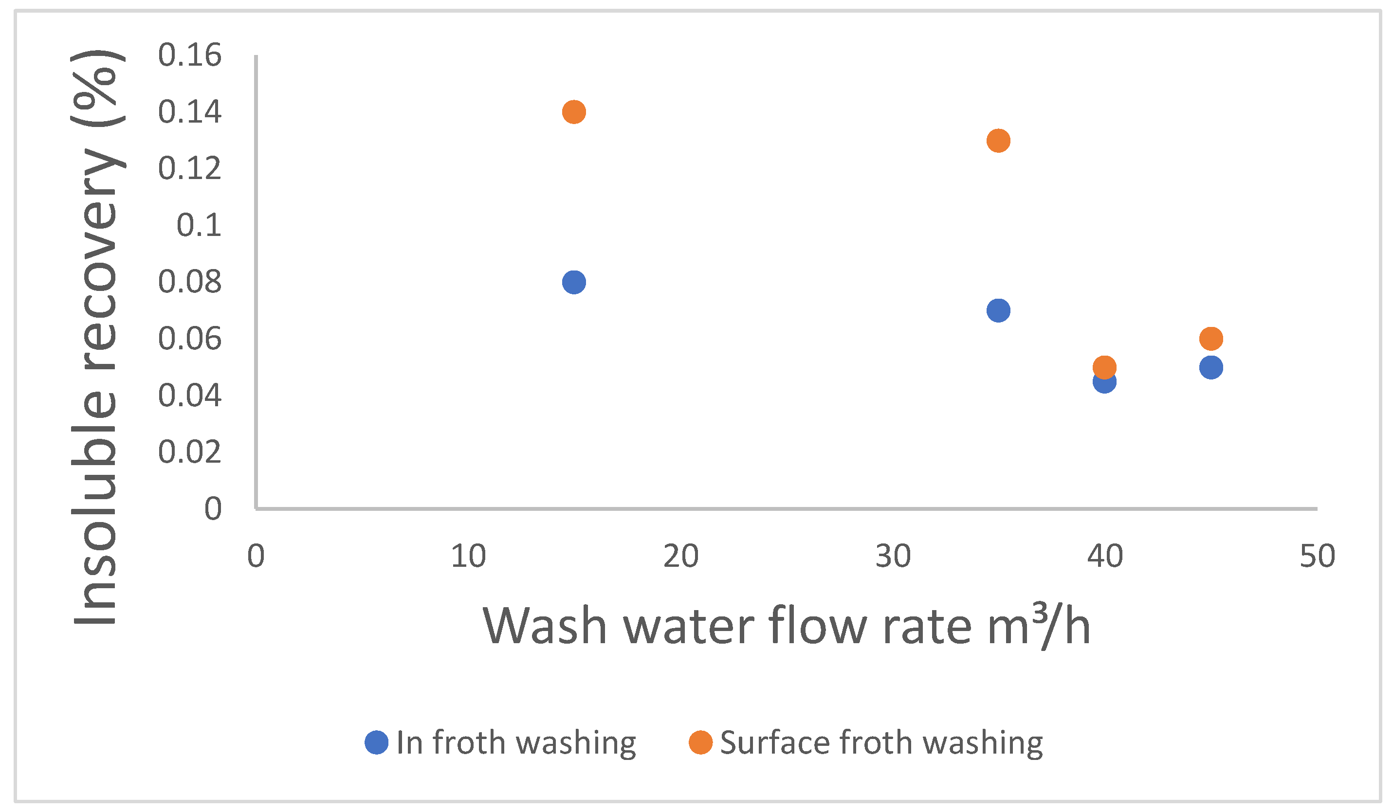
Figure 3.
Wash-water distribution nozzles, (a) Nozzles that cover the whole froth surface area [30]; (b) Angled nozzle; (c) Disc type nozzle; (d) Chamber type nozzle; (e) Flat nozzle [30].
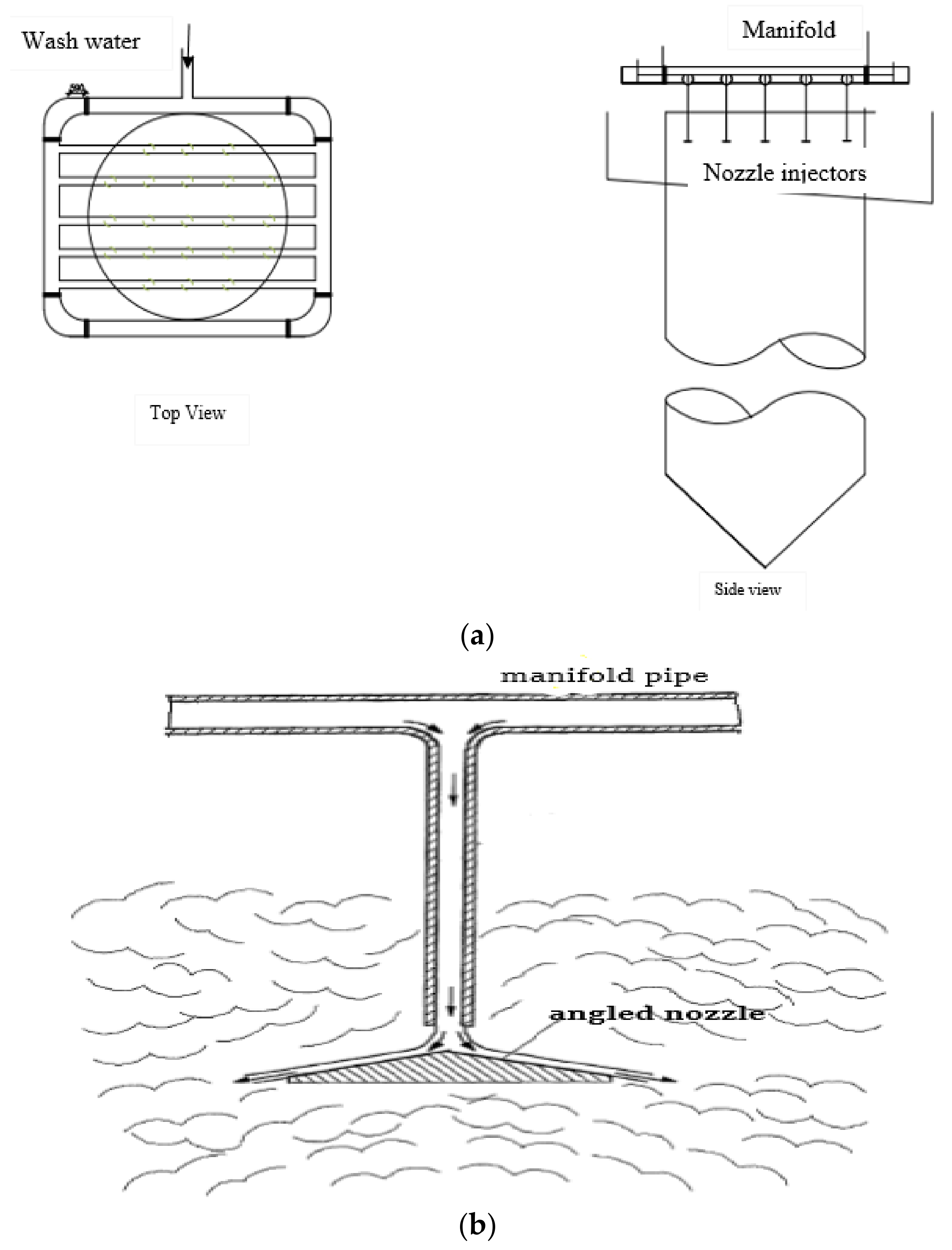
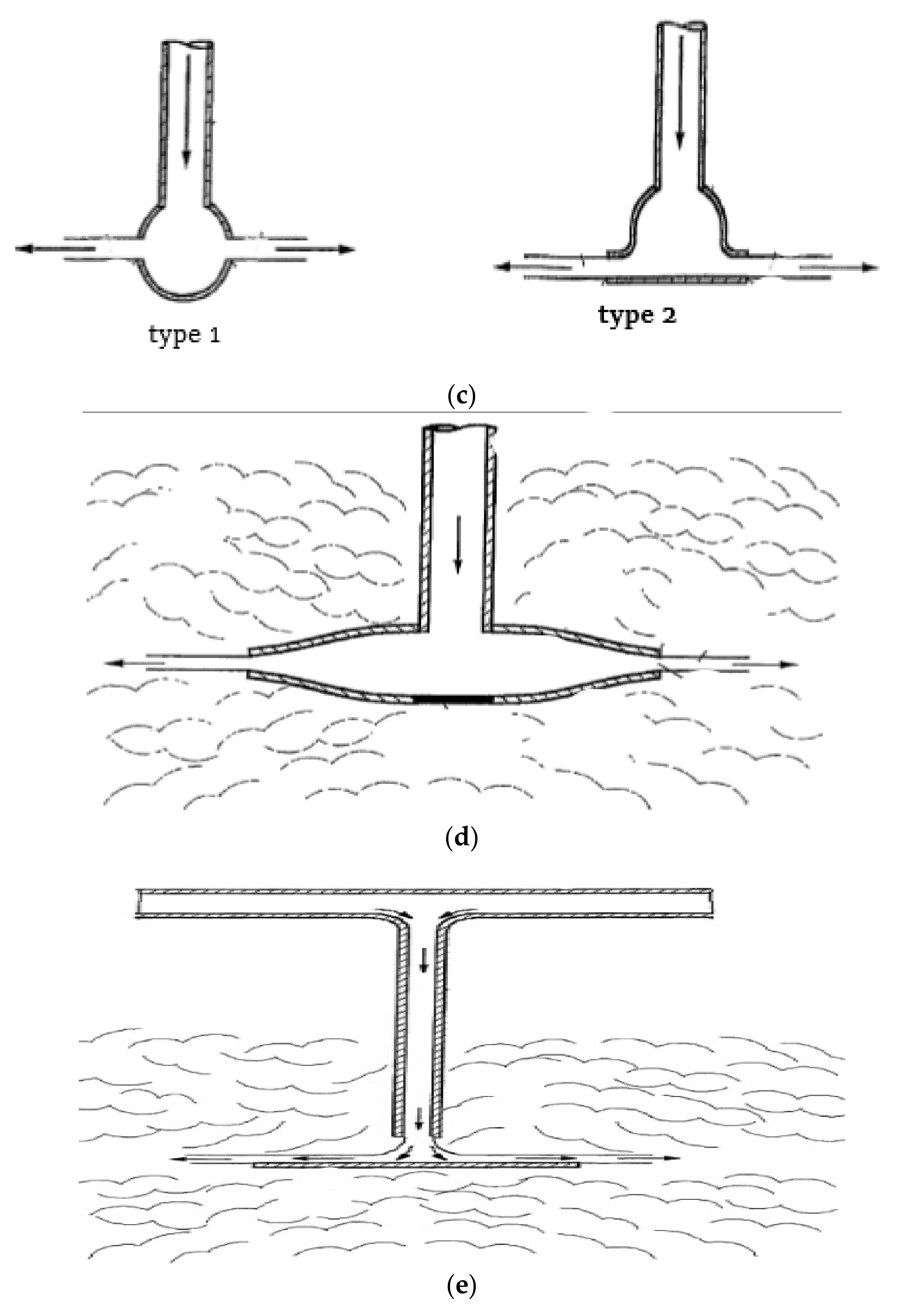
Figure 4.
Perforated pipes on top of the froth [39].
Figure 4.
Perforated pipes on top of the froth [39].
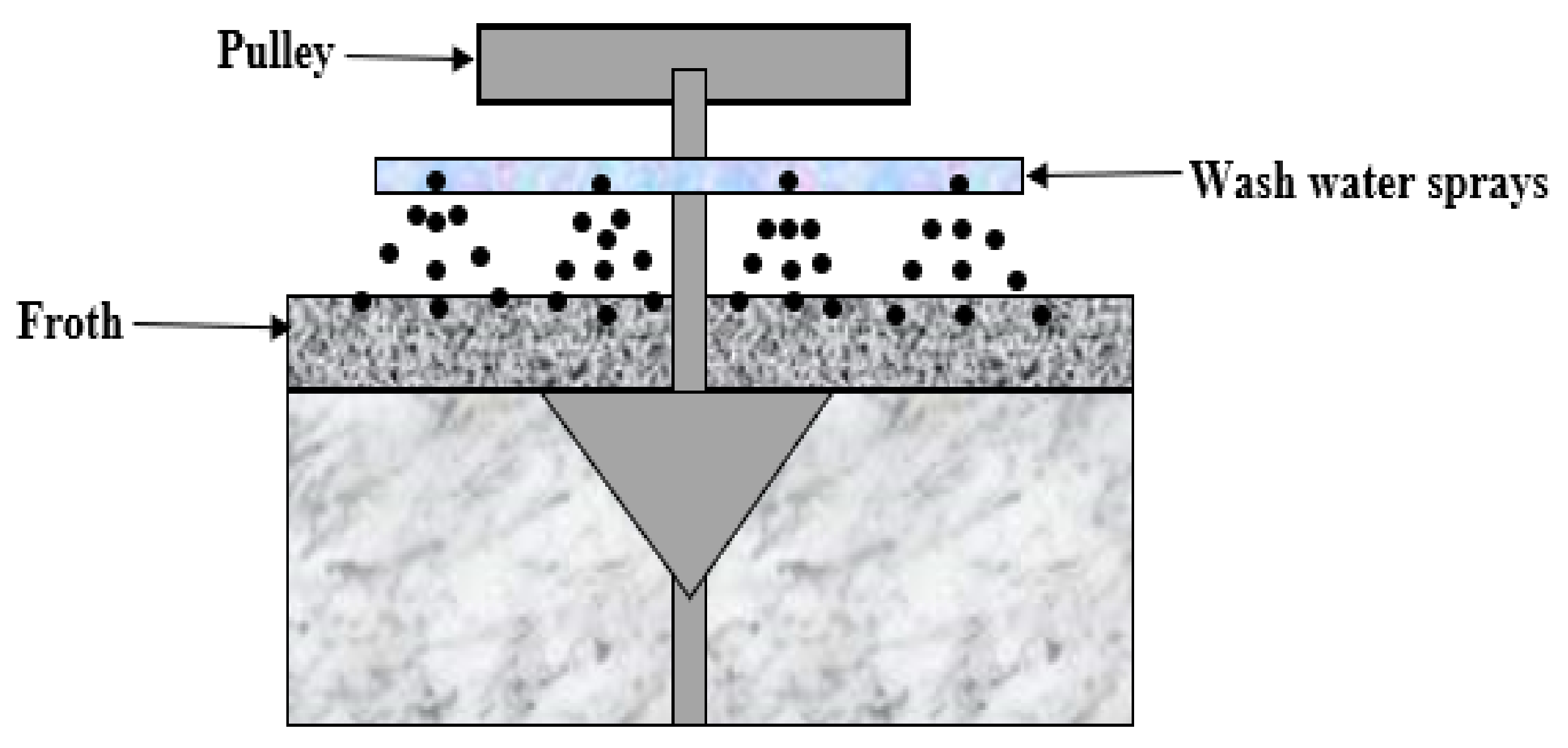
Figure 5.
Perforated pipes on top of the froth on a Jameson Cell during coal froth washing [40].
Figure 5.
Perforated pipes on top of the froth on a Jameson Cell during coal froth washing [40].
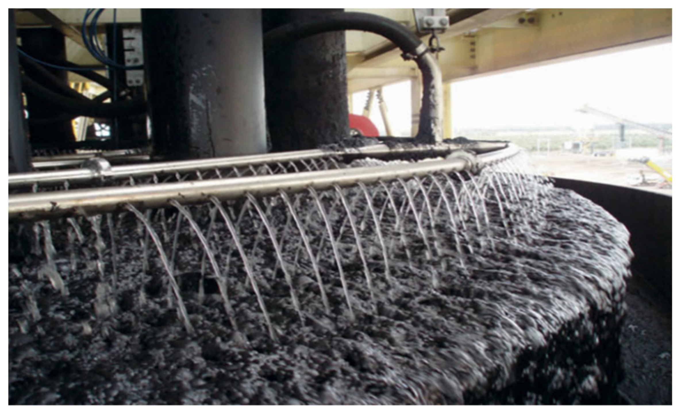
Figure 6.
Wash-water box [29].
Figure 6.
Wash-water box [29].

Figure 7.
Wash-water trays [40].
Figure 7.
Wash-water trays [40].

Figure 8.
Lip washing on a Dual Cell Flotation Cell [97].
Figure 8.
Lip washing on a Dual Cell Flotation Cell [97].

Figure 9.
Plunging/submerged nozzles, (a) Submerged horizontal (T-shaped) injector used to inject a horizontal jet of wash water into the froth column; (b) Photograph of a plunging jet/vertical injector in froth, and indications of how wash water moves in the froth when using a vertical plunger [38].

Figure 10.
Column cells with a wash water system [29].
Figure 10.
Column cells with a wash water system [29].

Figure 11.
Jameson cell with a froth washing system [32].
Figure 11.
Jameson cell with a froth washing system [32].

Figure 12.
Effect of wash-water ratio on recovery in the flotation of copper retreatment [34].
Figure 12.
Effect of wash-water ratio on recovery in the flotation of copper retreatment [34].

Figure 13.
Effect of wash-water ratio on grade in the flotation of fine copper retreatment stream [34].
Figure 13.
Effect of wash-water ratio on grade in the flotation of fine copper retreatment stream [34].
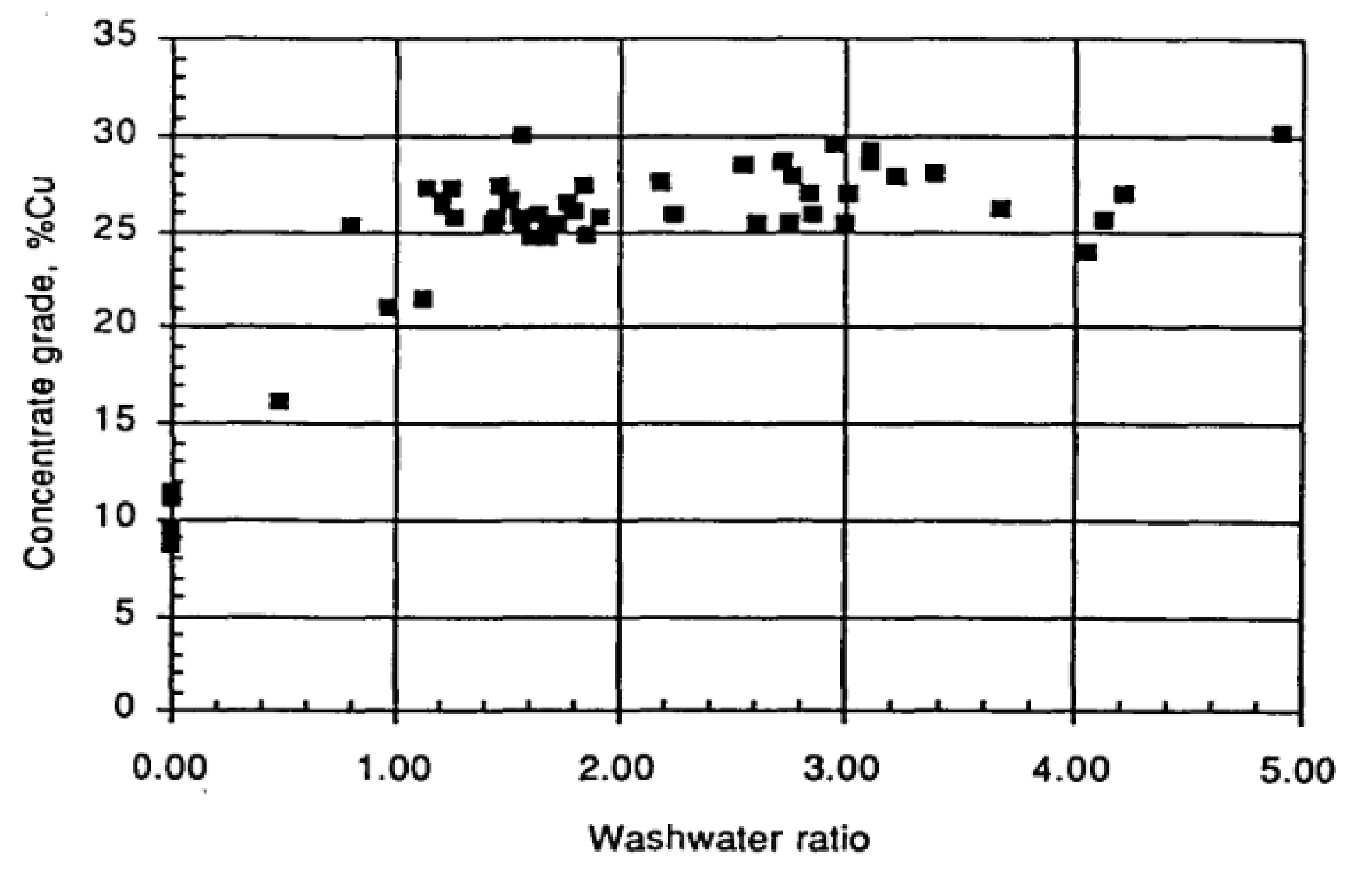

Table 1.
Composition of two available water sources at a mine site [100].
Table 1.
Composition of two available water sources at a mine site [100].
| Species | Concentration (mmol/L) | |
|---|---|---|
| Fresh Water | Tailing’s Water | |
| Ca2+ | 0.207 | 2.17 |
| Mg2+ | 0.118 | 0.45 |
| F− | 0.006 | 0.25 |
| SO42− | 0.005 | 0.67 |
Table 2.
Summary of the advantages and disadvantages of nozzles.
| Advantages of Using Nozzles | Disadvantages of Using Nozzles |
|---|---|
|
|
Table 3.
Advantages and disadvantages of froth washing.
| Method | Advantages | Disadvantages |
|---|---|---|
| Froth washing in general |
| |
| Washing on top of the froth, i.e., wash-water boxes/trays/pipes and jets |
|
|
| Internal froth washing |
| |
| Lip washing |
| |
| Under-froth washing |
|
Publisher’s Note: MDPI stays neutral with regard to jurisdictional claims in published maps and institutional affiliations. |
© 2022 by the authors. Licensee MDPI, Basel, Switzerland. This article is an open access article distributed under the terms and conditions of the Creative Commons Attribution (CC BY) license (https://creativecommons.org/licenses/by/4.0/).
Share and Cite
MDPI and ACS Style
Jera, T.M.; Bhondayi, C. A Review on Froth Washing in Flotation. Minerals 2022, 12, 1462. https://doi.org/10.3390/min12111462
AMA Style
Jera TM, Bhondayi C. A Review on Froth Washing in Flotation. Minerals. 2022; 12(11):1462. https://doi.org/10.3390/min12111462
Chicago/Turabian StyleJera, Tawona Martin, and Clayton Bhondayi. 2022. "A Review on Froth Washing in Flotation" Minerals 12, no. 11: 1462. https://doi.org/10.3390/min12111462
Note that from the first issue of 2016, this journal uses article numbers instead of page numbers. See further details here.