
Responses of Pre-Holed Granite under Coupled Biaxial Loading and Unloading Stress Condition


School of Resources and Safety Engineering, Central South University, Changsha 410083, China
*
Author to whom correspondence should be addressed.
Minerals 2022, 12(3), 372; https://doi.org/10.3390/min12030372
Submission received: 7 February 2022
/
Revised: 2 March 2022
/
Accepted: 15 March 2022
/
Published: 17 March 2022
Abstract
:Underground excavation is a necessary process for constructing mines, tunnels and depots in granite rock mass. In this study, the numerical granite specimens were established by the discrete element method and confirmed by laboratory experiments in order to investigate the peak stress, cracking development and failure properties of pre-holed granite under coupled biaxial loading and unloading conditions. The results show that, for the specimens containing D-type and square holes, the peak biaxial unloading strengths first decrease, then increase and finally decrease as the inclination angles of the holes increase. For the specimens with elliptical holes, the peak biaxial unloading strengths first decrease and then increase with the increases in the inclination angles of the holes. The biaxial unloading strengths of specimens containing elliptical, circular, D-type and square holes decrease in that order. The cracks initially appear near the crossover points between the X-type shear fracturing plane and the pre-hole in the center and gradually expand along the X-type shear direction, which indicates that the failure of pre-holed granite is primarily shear failure. When the overall length of cracks expanding along the X-type shear direction extends to the size of the pre-hole in the center, the failure of the pre-holed specimen occurs. When the existing pre-hole in the center of the granite specimen extends to connect with the shear slip in the vicinity of the hole, this triggers overall failure.
1. Introduction
A great deal of underground rock engineering, such as mines, tunnels and depots, is excavated and constructed in granite rock mass [1,2]. In underground rock engineering, there are diverse ranges of the stress conditions and shapes of excavation spaces, and the different stress conditions and excavation conditions have a strong influence on the stability of the rock mass [3,4,5,6]. Therefore, it is important to study the damage of different prefabricated borehole rocks and the crack propagation for the stability control of underground rock engineering. Many scholars have conducted numerous studies on rock and rock-like specimens containing prefabricated fractures and holes and have investigated the effects of different angles, stress conditions, and hole shapes on the fracture-expansion patterns and mechanical properties of the specimens [7,8,9,10]. Huang et al. [11] conducted uniaxial compression tests on granite specimens containing three non-congruent holes and analyzed the relationship between stress, acoustic emission and crack evolution processes using acoustic emission measurement and photographic monitoring techniques. Zeng et al. [12] investigated the mechanical properties and cracking behavior of perforated specimens under uniaxial compressive loading through indoor tests; the results showed that the shape of the perforation has a large influence on the uniaxial compressive strength and damage mode. Yang et al. [13] conducted uniaxial compression tests on red sandstone specimens containing two elliptical defects using a rock mechanics servo-controlled test system, and, based on the test results, analyzed in detail the effects of angles on the mechanical parameters and fracture processes of sandstone specimens containing two elliptical cracks.
The discrete element method (DEM) is a popular method for studying the crack penetration of rock specimens containing pores and multiple cracks. In recent years, many scholars have carried out much relevant research using DEM [14,15,16,17,18,19,20]. Fan et al. [21] prepared both cracks and round holes in real rock materials by changing the tilt angle of the cracks and combining different methods of crack generation. Based on the experimental results, a particle flow calculation program was used to reveal the stress distribution around the cracks and holes and explain the cracking mechanism of rock specimens containing cracks and round holes under uniaxial compression conditions. Chen et al. [22] used the DEM to simulate the unloading response of intact and pre-defective rock masses based on the unloading stress conditions during their excavation. Yang et al. [23] performed systematic numerical simulations of uniaxial compression on rock-like specimens containing two non-parallel cracks and compared the strength and deformation properties and crack evolution processes of the pre-defective specimens with the results of corresponding indoor tests.
During the excavation of underground cavities, coupled loading and unloading damage occurs near the rock mass. However, previous studies have mainly focused on the uniaxial compression of rocks containing holes, with less attention paid to specimens containing holes of different shapes under coupled biaxial loading and unloading conditions. Therefore, it is necessary to study the mechanical properties and damage characteristics of rock specimens containing holes of different shapes and with different inclination angles (the orientation of the hole, which is defined as the angle between the hole axis and the vertical axis) under coupled biaxial loading and unloading conditions. In this study, a set of micromechanical parameters in the particle flow code software (PFC) was calibrated using the simulation results of uniaxial compression and biaxial compression, and systematic numerical simulations of coupled biaxial loading and unloading were carried out for square specimens containing round, square, elliptical, and D-type holes in the center. The mechanical properties and crack penetration processes were then analyzed in detail.
2. Methodology
2.1. Numerical Model
We conducted this study using the particle flow code software (PFC2D) (PFC2D 5.0, ITASCA, Minneapolis, MN, USA) based on the discrete element method. The macro-mechanical parameters of the rock in the numerical model were calibrated by a test on a standard cylindrical specimen with dimensions of φ50 × 100 mm. Firstly, a standard cylindrical numerical specimen with a size of 50 mm × 100 mm was created. A parallel-bonded contact model was used, and the cylindrical specimen contained 12,952 particles and 30,641 contacts with a particle size distribution range of 0.25–0.415 mm. The cylindrical specimen was tested in uniaxial compression with a displacement-controlled loading speed of 0.01 m/s. After a series of repeated tests, a set of suitable microscopic parameters (Table 1) was obtained to establish the numerical granite specimens. For the uniaxial compression on the standard cylindrical specimen, the numerical and experimental results are shown in Figure 1 and Table 2. From Table 2, it can be seen that the uniaxial compressive strength, Young’s modulus and Poisson’s ratio of the standard cylindrical specimens are approximately the same between the numerical and experimental values. The error values compared with the numerical and experimental values of the uniaxial compressive strength and Young’s modulus are 0.07% and 0.66%, respectively. It can be seen from Figure 1 that the numerical and experimental peak strengths and the rock failure modes are well fitted. Both the experimental and numerical models show an axial cleavage failure mode. However, the numerical model cannot simulate the initial compression-density phase of the stress–strain curve, resulting in a final peak strain that is smaller than the experimental value. The reason for this is that the present numerical model does not consider the pre-existing cracks in natural granite rock. Fortunately, because this study mainly aims to investigate the peak strength and failure characteristic of pre-holed granite, the numerical model mentioned above can satisfy the requirements of this study.
In order to verify the accuracy of the numerical model, two square granite specimens with dimensions of 100 mm × 30 mm × 100 mm were made in order to conduct a uniaxial compression test, whose result could be compared with the numerical simulation result. One fissure and a single circular hole were prepared in square specimens. As shown in Figure 2, the crack propagation and failure mode of the granite specimen were similar to those of the numerical specimen. The mechanical properties and failure modes of the numerical specimens are very close to those of the real granite specimens. Therefore, the numerical specimens can reproduce the mechanical behavior of granite specimens.
2.2. Pre-Holed Specimens
After the microscopic parameters were calibrated, square numerical specimens of 100 mm × 100 mm were established, and pre-holes with different shapes and inclination angles were formed by deleting spherical particles in the numerical models. The established intact square numerical specimen contained 25,920 round particles and 62,275 contacts. The intact square numerical specimen and the pre-holed specimens after deleting the particles are shown in Figure 3 and Figure 4, respectively.
2.3. Loading Paths
The stress in the surrounding rock around the opening will change with a decrease in the radial direction and an increase in the tangential direction. In addition, the stress in the rock at the front of the excavation face will change with a decrease in the excavation unloading direction and an increase in the support direction. Therefore, the coupled biaxial loading and unloading process is a common stress path in the engineering rock mass. Meanwhile, uniaxial compression and biaxial compression tests should be conducted to obtain the uniaxial compressive strength and biaxial compressive strength of rock specimens to determine the stress levels before unloading. Three stress paths were used in this test—uniaxial compression, biaxial compression, and coupled biaxial loading and unloading—as shown in Figure 5. In uniaxial compression, σ1 was loaded at a loading speed of 0.01 m/s until rock failure. In biaxial compression, σ1 and σ2 were first increased to 20 MPa simultaneously, σ2 was kept constant at 20 MPa, and σ1 was continuously increased at a loading speed of 0.01 m/s until rock failure. The pre-loading process of coupled biaxial loading and unloading is the same as that of biaxial compression, but when σ1 reached half of the sum of the uniaxial compression strength and the biaxial compression strength, the servo program was rewritten to unload σ2 at a rate of 1 MPa/ms and σ1 continued to be increased at a loading speed of 0.01 m/s until rock failure to simulate the excavation-induced stress change path.
3. Results and Discussion
3.1. Peak Stresses at Rock Failure
The peak stress parameters of the numerical specimens containing different prefabricated holes under uniaxial compression, biaxial compression and coupled loading and unloading stress conditions are listed in Table 3. The peak value of axial stress σ1 during uniaxial compression is defined as the uniaxial compression strength (σucs). The peak axial stress σ1 in biaxial compression is defined as the biaxial compressive strength (σbcs). The σ(ucs + bcs)/2 is half of the sum of σucs and σbcs. The peak axial stress σ1 under coupled biaxial loading and unloading is defined as the peak biaxial unloading strength (σbu), and the corresponding lateral stress σ2 is defined as the peak biaxial unloading lateral stress (σls).
The peak stresses at failure of the numerical granite specimens containing different prefabricated holes were compared and are shown in Figure 6. For the same specimens, the peak stresses at rock failures are, in decreasing order, from cases under biaxial compression, from cases under coupled biaxial loading and unloading conditions, and finally from cases under uniaxial compression. Under the above three stress conditions of uniaxial compression, biaxial compression and coupled biaxial loading and unloading, the peak stress parameters present generally consistent change laws for different stress conditions as the inclination angles of the hole changes. For the specimens with D-type and square holes, the peak stress parameters first decrease, then increase and finally decrease with the increases in the inclination angles of holes, and the variation amplitude of the uniaxial compressive peak stress parameter is larger than those amplitudes under the biaxial compressive and coupled biaxial loading/unloading conditions because the lateral confining stress can restrict the crack dilation. For the specimens with elliptical holes, the uniaxial compressive strength first increases, secondly decreases and then increases, while the biaxial compressive strength and the peak biaxial unloading strength first decrease and then increase with the increases in the inclination angles of the holes. For the specimens with a hole with an inclination angle of 0°, the uniaxial compressive strengths of specimens with circular, elliptical, D-type and square holes decrease in that order, while the biaxial compressive strengths and the biaxial unloading strengths of specimens with elliptical, circular, D-type and square holes decrease in that order. These results indicate that the lateral confinement can improve the strength of specimens containing elliptical holes more significantly, and rocks containing square holes are the most prone to instability because stress concentration is most likely to occur at the corners of the square hole. In addition, the corresponding peak biaxial unloading lateral stress at rock failure under coupled biaxial loading and unloading conditions fluctuates from 13 to 16 MPa without an obvious change law for all specimens.
3.2. Cracking Development
The axial stress–time curves, lateral stress–time curves, and the changes in instantaneous crack numbers and cumulative crack numbers simulated by PFC2D under coupled biaxial loading and unloading conditions are summarized in Figure 7 for all types of granite specimens. The results show that the cracks start to appear obviously from the unloading point and rapidly increase near the peak stress. Namely, the cumulative number of cracks grows slowly before unloading and subsequently rises fast from the unloading point, and the growth rate of cracks after the peak stress is significantly higher than that before the peak stress, which indicates that the primary growth period of cracks is near the post-peak damage stage after peak strength. In addition, the number of shear cracks is generally larger than that of tensile cracks during the loading and unloading process, and the difference in numbers between shear and tensile cracks increases significantly after the peak stress, indicating that the failure of the pre-holed granite specimens was dominated by shear failure.
The crack development processes at the six stages (A to F shown in Figure 7) during coupled biaxial loading and unloading are shown in Figure 8 for all the types of granite specimens. In the figures, the red points indicate cracks. Stages at A and B are before the peak stress; stage C is at the peak stress; and stages at D, E and F are after the peak stress. The number of cracks for the different shapes and orientations of the holes increases gradually with the axial stress, which increases slowly before the peak stress and starts to appear in abundance after the peak stress. Before the peak stress, the cracks appear mainly around the hole. At the peak stress, the cracks near the hole expand outward along X-type shear directions, and cracks start to appear at the four corners of the specimen and expand inward along the X-type shear directions. After the peak stress, the cracks expanding from the hole and corners gradually connect with one another, and finally present a X-type shear overall failure and cross the hole in the center. The above results show that the pre-holed granite specimen primarily undergoes shear failure under coupled biaxial loading and unloading conditions. For granite specimens with a D-type hole, the cracks initially appear at the bottom corner and the top arch foot of the hole when the inclination angle of the hole is 0°. The initial cracking is then gradually transferred to the arch top and finally to the arch foot on the other side of hole; meanwhile, the initial cracking at the bottom corner of the hole is gradually transferred to the middle of the square side to the bottom corner on the other side of the hole as the inclination angle of the hole changes from 0° to 90°. For granite specimens with a square hole, the cracks initially appear at the bottom corner and top corner when the inclination angle of the hole is 0°. The initial cracking around the hole is gradually transferred to the middle of the square side and finally to the bottom and top corners on the other side of the hole as the inclination angle of the hole changes from 0° to 90°. For granite specimens with a circular hole, the cracks initially appear near the boundaries of the circular hole. For granite specimens with an elliptical hole, the cracks initially appear near the corners of the elliptical hole when the inclination angle of the hole is 0°, and the initial cracking around the hole is gradually transferred to the middle of the long-arched edges of the elliptical hole as the inclination angle of the hole changes from 0° to 90°. In summary, the cracks initially appear near the crossover points between the X-type shear fracturing plane and the hole, and gradually expand along the X-type shear direction, resulting in the dominated shear failure of the square pre-holed granite specimen under coupled biaxial loading and unloading conditions.
3.3. Failure Properties
The failure modes of different pre-holed specimens at the peak stress under coupled biaxial loading and unloading conditions are shown in Figure 9. It can be seen from Figure 9 that the granite specimen will be unstable and reach the peak strength when the overall length of cracks expanding along the X-type shear direction extends to the size of the pre-hole in the center. In addition, the overall instability of the pre-holed granite specimen is triggered from the shear slip around the vicinity of the hole. The existing pre-hole in the center of the granite specimen will cause the overall failure of crossing the hole.
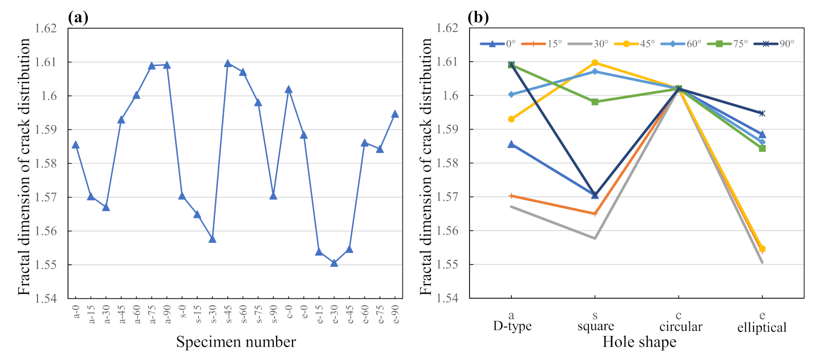
The ultimate failure modes for different pre-holed granite specimens under coupled biaxial loading and unloading conditions are listed in Figure 10. The ultimate failure mode shows that the pre-holed granite specimen finally presents X-type shear failure, and the X-type shear failure plane passes through the hole in the center. The fractal dimension can quantitatively describe the development degree and distribution characteristics of crack propagation in the granite specimen. The high fractal dimension of the crack network indicates that the crack propagation becomes denser and more complex. In order to analyze the crack propagation in the ultimate failure mode of the specimen, the fractal dimension of the crack network was calculated by the box dimension method and is shown in Figure 11. The results indicate that the fractal dimensions of the crack propagations for the specimens containing a D-type hole and an elliptical hole present a decrease followed by an increase as the inclination angle of the pre-hole changes from 0° to 90°. The fractal dimensions of crack propagations for the specimens containing a square hole decrease first, then increase and finally decrease instead as the inclination angle of the pre-hole changes from 0° to 90°. For specimens containing a hole with an inclination angle of 0°, the fractal dimensions present a decrease, in the following order, for specimens with a circular, elliptical, D-type and square hole in the center. Overall, the variation in the fractal dimension of ultimate failure is generally consistent with the change trend of the peak strengths of pre-holed granite specimens. In general, the pre-holed granite specimens with lower peak stresses present a smaller fractal dimension of ultimate failure with a more regular X-type shear cracking—for example, the specimens containing a pre-hole with an inclination angle of 30° which have the lowest peak stress and fractal dimension.
4. Conclusions
In this study, the numerical granite specimens were established by the discrete element method and confirmed by uniaxial compression experiments of a standard cylindrical specimen and a pre-flawed specimen. Hereafter, coupled biaxial loading and unloading tests were conducted on the numerical granite specimens to investigate the peak stress, cracking development and failure properties of specimens containing pre-holes of different shapes and inclination angles (the orientation of the hole, which is defined as the angle between the hole axis and the vertical axis). The efforts and results can provide valuable information for the excavation stability of openings in granite rock mass. The following conclusions can be drawn:
(a) For the specimens with D-type and square holes, the peak biaxial unloading strengths first decrease, then increase and finally decrease as the inclination angles of the holes increase. For the specimens with elliptical holes, the peak biaxial unloading strength first decreases and then increases with increases in the inclination angles of the holes. The biaxial unloading strengths of specimens with elliptical, circular, D-type and square holes decrease, in that order. Rock containing a square hole is the most prone to instability, compared to other granite specimens.
(b) The cracks start to appear obviously from the unloading point and rapidly increase near the peak stress, and the failure of pre-holed granite specimens was mainly dominated by shear failure. The cracks mainly appear around the hole before the peak stress stage, the cracks near the hole expand outward along the X-type shear directions at the peak stress, and the cracks expanding from the hole and corners gradually connect together and finally present a X-type shear failure overall and cross the hole in the center after the peak stress. In general, the cracks initially appear near the crossover points between the X-type shear fracturing plane and the pre-hole in the center and gradually expand along the X-type shear direction.
(c) The failure of the pre-holed specimen occurs and the axial stress reaches peak strength under the coupled biaxial loading and unloading conditions when the overall length of the cracks expanding along the X-type shear direction extends to the size of the pre-hole in the center. The existing pre-hole in the center of a granite specimen will lead to overall failure that crosses the hole, triggered by shear slip around the vicinity of the hole.
Author Contributions
Conceptualization, S.W. and Z.Z.; methodology, Z.P.; software, Y.J.; validation, S.W. and Z.Z.; formal analysis, Z.P.; investigation, Z.P. and Y.J.; writing—original draft preparation, Z.P. and Y.J.; writing—review and editing, Z.Z., Z.P., Y.J. and S.W.; supervision, S.W. and Z.Z.; funding acquisition, S.W. All authors have read and agreed to the published version of the manuscript.
Funding
The work presented in this paper was financially supported by the National Natural Science Foundation of China (Grant No. 52174099, 51904333), the Natural Science Foundation of Hunan Province (No. 2021JJ30842), Young Talent Support Project of China Association for Science and Technology (No. YSXH 2020-QT002), and Changsha Outstanding Innovative Youth Program (No. kq2107003).
Conflicts of Interest
The authors declare no conflict of interest.
References
- Patel, S.; Martin, C.D. Effect of Stress Path on the Failure Envelope of Intact Crystalline Rock at Low Confining Stress. Minerals 2020, 10, 1119. [Google Scholar] [CrossRef]
- Nguyen, T.S. Progressive Damage of a Canadian Granite in Laboratory Compression Tests and Underground Excavations. Minerals 2021, 11, 10. [Google Scholar] [CrossRef]
- Park, C.H.; Bobet, A. Crack coalescence in specimens with open and closed flaws: A comparison. Int. J. Rock Mech. Min. Sci. 2009, 46, 819–829. [Google Scholar] [CrossRef]
- Wang, S.Y.; Sloan, S.W.; Sheng, D.C.; Tang, C.A. 3D numerical analysis of crack propagation of heterogeneous notched rock under uniaxial tension. Tectonophysics 2016, 677–678, 45–67. [Google Scholar] [CrossRef]
- Wang, S.; Tang, Y.; Wang, S. Influence of brittleness and confining stress on rock cuttability based on rock indentation tests. J. Cent. South Univ. 2021, 28, 2786–2800. [Google Scholar] [CrossRef]
- Wang, S.; Tang, Y.; Li, X.; Du, K. Analyses and predictions of rock cuttabilities under different confining stresses and rock properties based on rock indentation tests by conical pick. Trans. Nonferrous Met. Soc. China 2021, 31, 1766–1783. [Google Scholar] [CrossRef]
- Huang, D.; Gu, D.; Yang, C.; Huang, R.; Fu, G. Investigation on Mechanical Behaviors of Sandstone with Two Preexisting Flaws under Triaxial Compression. Rock Mech. Rock Eng. 2016, 49, 375–399. [Google Scholar] [CrossRef]
- Yang, H.-Q.; Liu, J.-F.; Zhou, X.-P. Effects of the Loading and Unloading Conditions on the Stress Relaxation Behavior of Pre-cracked Granite. Rock Mech. Rock Eng. 2017, 50, 1157–1169. [Google Scholar] [CrossRef]
- Feng, X.-T.; Ding, W.; Zhang, D. Multi-crack interaction in limestone subject to stress and flow of chemical solutions. Int. J. Rock Mech. Min. Sci. 2008, 46, 159–171. [Google Scholar] [CrossRef]
- Yang, S.-Q.; Jing, H.-W. Strength failure and crack coalescence behavior of brittle sandstone samples containing a single fissure under uniaxial compression. Int. J. Fract. 2011, 168, 227–250. [Google Scholar] [CrossRef]
- Huang, Y.-H.; Yang, S.-Q.; Ranjith, P.; Zhao, J. Strength failure behavior and crack evolution mechanism of granite containing pre-existing non-coplanar holes: Experimental study and particle flow modeling. Comput. Geotech. 2017, 88, 182–198. [Google Scholar] [CrossRef]
- Zeng, W.; Yang, S.-Q.; Tian, W.-L. Experimental and numerical investigation of brittle sandstone specimens containing different shapes of holes under uniaxial compression. Eng. Fract. Mech. 2018, 200, 430–450. [Google Scholar] [CrossRef]
- Yang, S.-Q.; Huang, Y.-H.; Tian, W.-L.; Zhu, J. An experimental investigation on strength, deformation and crack evolution behavior of sandstone containing two oval flaws under uniaxial compression. Eng. Geol. 2017, 217, 35–48. [Google Scholar] [CrossRef]
- Bahaaddini, M.; Sharrock, G.; Hebblewhite, B.K. Numerical investigation of the effect of joint geometrical parameters on the mechanical properties of a non-persistent jointed rock mass under uniaxial compression. Comput. Geotech. 2013, 49, 206–225. [Google Scholar] [CrossRef]
- Zhao, Z.-H.; Zhou, D. Mechanical properties and failure modes of rock samples with grout-infilled flaws: A particle mechanics modeling. J. Nat. Gas Sci. Eng. 2016, 34, 702–715. [Google Scholar] [CrossRef]
- Yoon, J. Application of experimental design and optimization to PFC model calibration in uniaxial compression simulation. Int. J. Rock Mech. Min. Sci. 2007, 44, 871–889. [Google Scholar] [CrossRef]
- Areias, P.; Dias-da-Costa, D.; Alfaiate, J.; Júlio, E. Arbitrary bi-dimensional finite strain cohesive crack propagation. Comput. Mech. 2009, 45, 61–75. [Google Scholar] [CrossRef]
- Cao, R.-H.; Cao, P.; Fan, X.; Xiong, X.; Lin, H. An Experimental and Numerical Study on Mechanical Behavior of Ubiquitous-Joint Brittle Rock-Like Specimens Under Uniaxial Compression. Rock Mech. Rock Eng. 2016, 49, 4319–4338. [Google Scholar] [CrossRef]
- Chen, M.; Yang, S.-Q.; Ranjith, P.G.; Zhang, Y.-C. Cracking behavior of rock containing non-persistent joints with various joints inclinations. Theor. Appl. Fract. Mech. 2020, 109, 102701. [Google Scholar] [CrossRef]
- Ding, X.; Zhang, L. A new contact model to improve the simulated ratio of unconfined compressive strength to tensile strength in bonded particle models. Int. J. Rock Mech. Min. Sci. 2014, 69, 111–119. [Google Scholar] [CrossRef]
- Fan, X.; Li, K.; Lai, H.; Xie, Y.; Cao, R.; Zheng, J. Internal stress distribution and cracking around flaws and openings of rock block under uniaxial compression: A particle mechanics approach. Comput. Geotech. 2018, 102, 28–38. [Google Scholar] [CrossRef]
- Chen, Z.-H.; Li, X.-B.; Weng, L.; Wang, S.; Dong, L. Influence of Flaw Inclination Angle on Unloading Responses of Brittle Rock in Deep Underground. Geofluids 2019, 4657645. [Google Scholar] [CrossRef] [Green Version]
- Yang, S.-Q.; Huang, Y.-H. Failure behaviour of rock-like materials containing two pre-existing unparallel flaws: An insight from particle flow modeling. Eur. J. Environ. Civ. Eng. 2018, 22 (Suppl. 1), 57–78. [Google Scholar] [CrossRef]
Figure 1.
Comparison of experimental and numerical stress–strain curves and failure modes for standard cylindrical granite specimens under uniaxial compression.
Figure 1.
Comparison of experimental and numerical stress–strain curves and failure modes for standard cylindrical granite specimens under uniaxial compression.
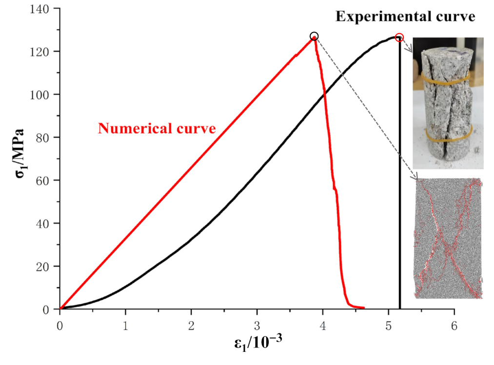
Figure 2.
Comparison of (a) the numerical and (b) experimental failure modes of rock specimens containing holes and fissures under uniaxial compression.
Figure 2.
Comparison of (a) the numerical and (b) experimental failure modes of rock specimens containing holes and fissures under uniaxial compression.

Figure 3.
Numerical model of intact specimen, including (a) intact specimen and (b) the structure of particles and contacts in the model.
Figure 3.
Numerical model of intact specimen, including (a) intact specimen and (b) the structure of particles and contacts in the model.
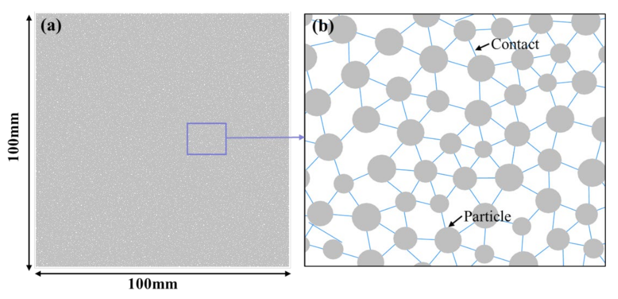
Figure 4.
Specimen models with different pre-holes, including (a) the size parameters of the pre-holed specimens and (b) numerical models of pre-holed specimens with a D-type hole with inclination angles of 0° (a-0), 15° (a-15), 30° (a-30), 45° (a-45), 60° (a-60), 75° (a-75), and 90° (a-90); a square hole with inclination angles of 0° (s-0/90), 15° (s-15), 30° (s-30), 45° (s-45), 60° (s-60), and 75° (s-75); and a circular hole (c-0), and elliptical hole with inclination angles of 0° (e-0), 15° (e-15), 30° (e-30), 45° (e-45), 60° (e-60), 75° (e-75), and 90° (e-90).
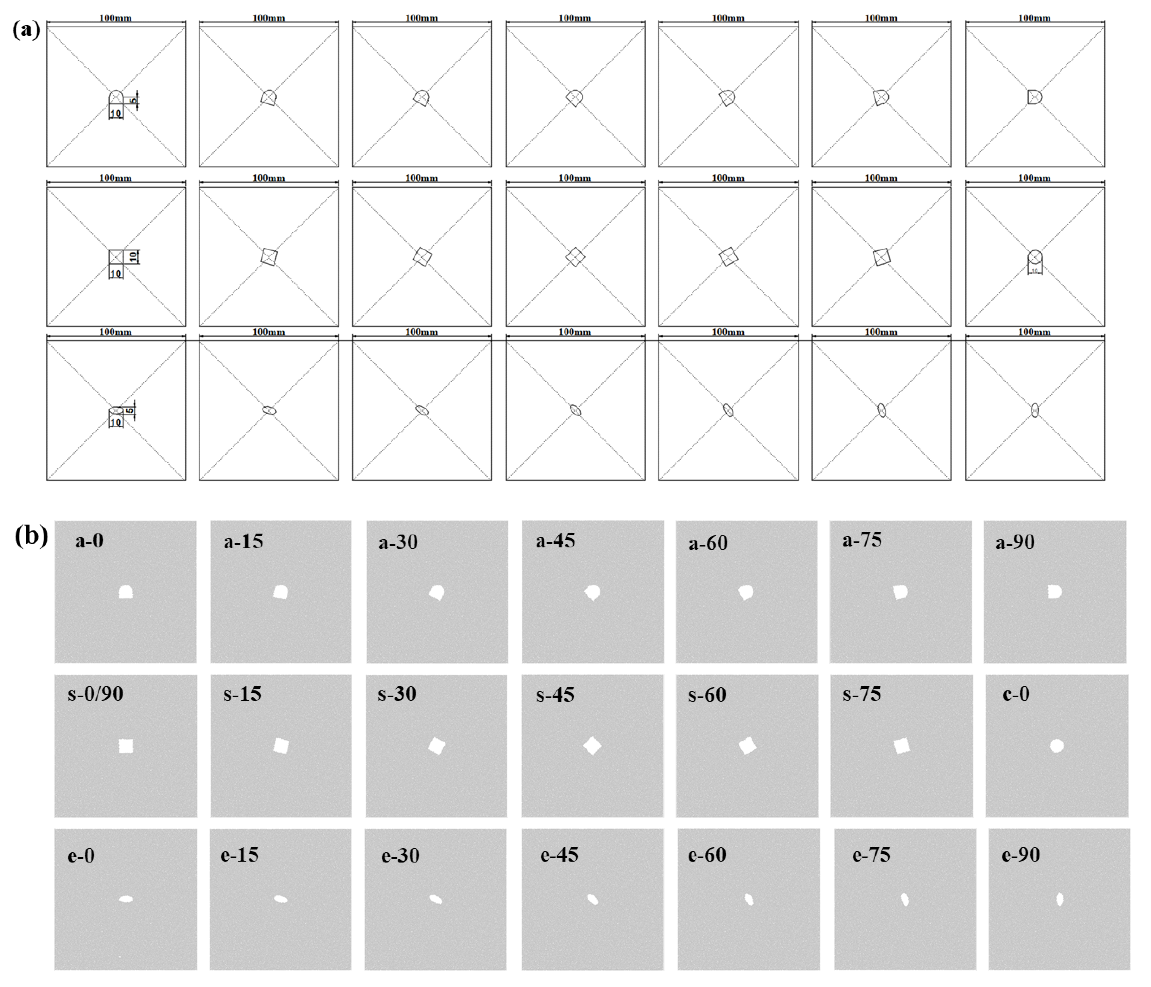
Figure 5.
Stress paths and loading schematic diagrams in the numerical simulations, including stress paths under (a) uniaxial compression, (b) biaxial compression, and (c) coupled biaxial loading and unloading, and the loading schematic diagrams under (d) uniaxial compression, (e) biaxial compression, and (f) coupled biaxial loading and unloading.

Figure 6.
Change curves of peak stresses at rock failure, including (a) changes in uniaxial compression strength (σucs), biaxial compressive strength (σbcs), peak biaxial unloading strength (σbu), and the corresponding peak biaxial unloading lateral stress (σls) for all specimens, and the peak stresses for specimens with (b) 0°, (c) 15°, (d) 30°, (e) 45°, (f) 60°, (g) 75°, and (h) 90° inclination angles.

Figure 7.
Changes in axial stress, crack numbers and cumulative crack numbers with time for all types of granite specimens under coupled biaxial loading and unloading conditions. (a) a-0; (b) a-15; (c) a-30; (d) a-45; (e) a-60; (f) a-75; (g) a-90; (h) s-0/90; (i) s-15; (j) s-30; (k) s-45; (l) s-60; (m) s-75; (n) c-0; (o) e-0; (p) e-15; (q) e-30; (r) e-45; (s) e-60; (t) e-75; (u) e-90. Point A–F: the six stages during crack development processes including the stages before peak stress (A and B), at the peak stress (C) and after the peak stress (D, E and F).
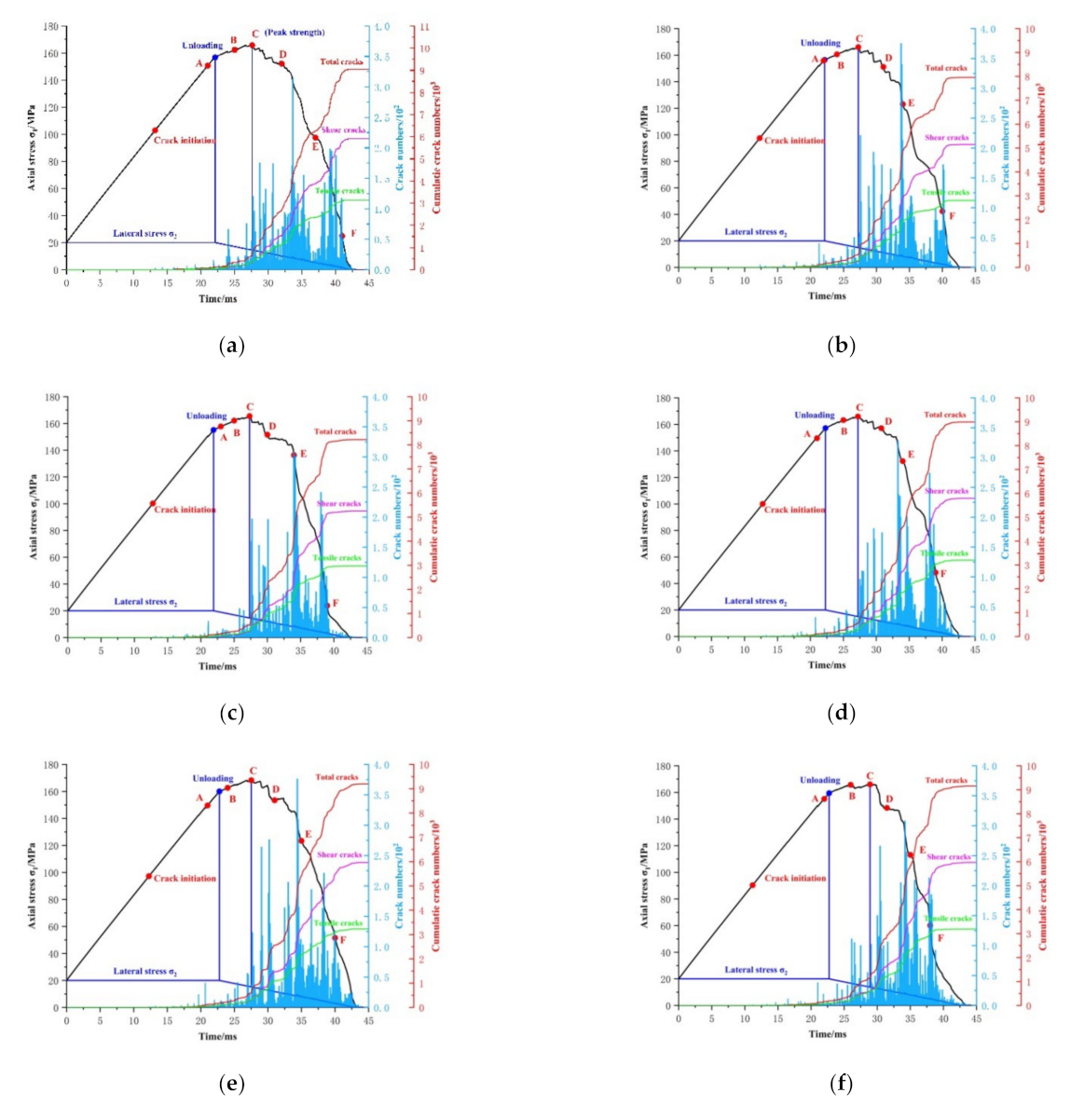
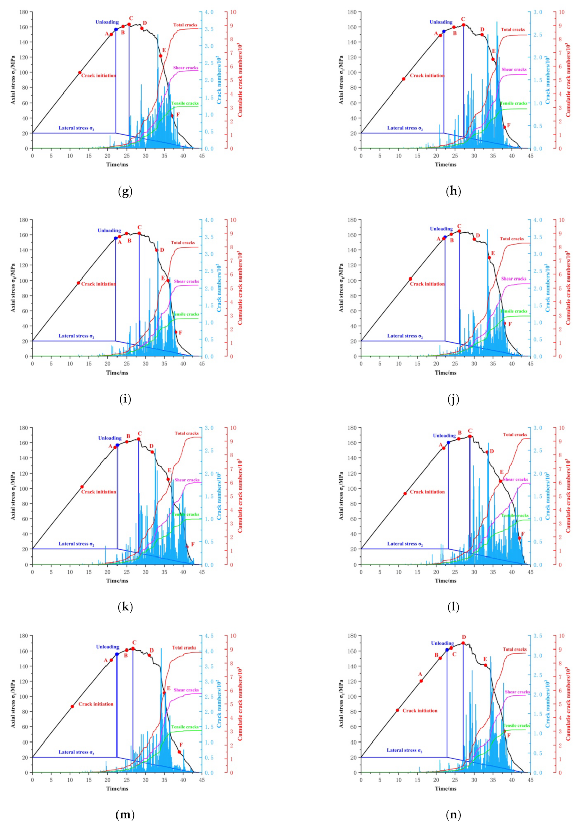

Figure 8.
Cracking developments of pre-holed granite specimens under coupled biaxial loading and unloading conditions. (a) a-0; (b) a-15; (c) a-30; (d) a-45; (e) a-60; (f) a-75; (g) a-90; (h) s-0/90; (i) s-15; (j) s-30; (k) s-45; (l) s-60; (m) s-75; (n) c-0; (o) e-0; (p) e-15; (q) e-30; (r) e-45; (s) e-60; (t) e-75; (u) e-90. Point A–F: the six stages during crack development processes including the stages before peak stress (A and B), at the peak stress (C) and after the peak stress (D, E and F).
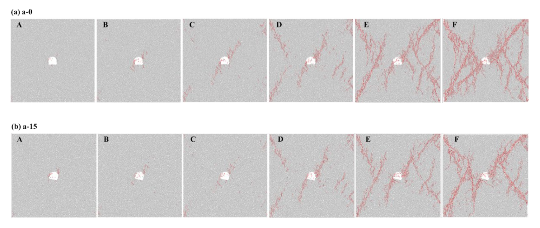
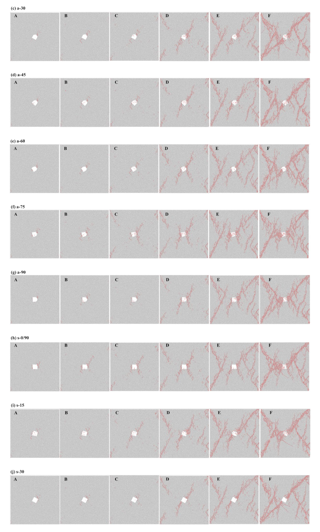
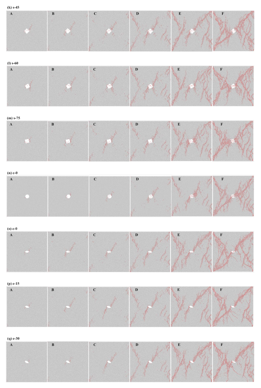

Figure 9.
Failure images of pre-holed specimens at the peak stress under coupled biaxial loading and unloading conditions. (a) a-0; (b) a-15; (c) a-30; (d) a-45; (e) a-60; (f) a-75; (g) a-90; (h) s-0/90; (i) s-15; (j) s-30; (k) s-45; (l) s-60; (m) s-75; (n) c-0; (o) e-0; (p) e-15; (q) e-30; (r) e-45; (s) e-60; (t) e-75; (u) e-90.
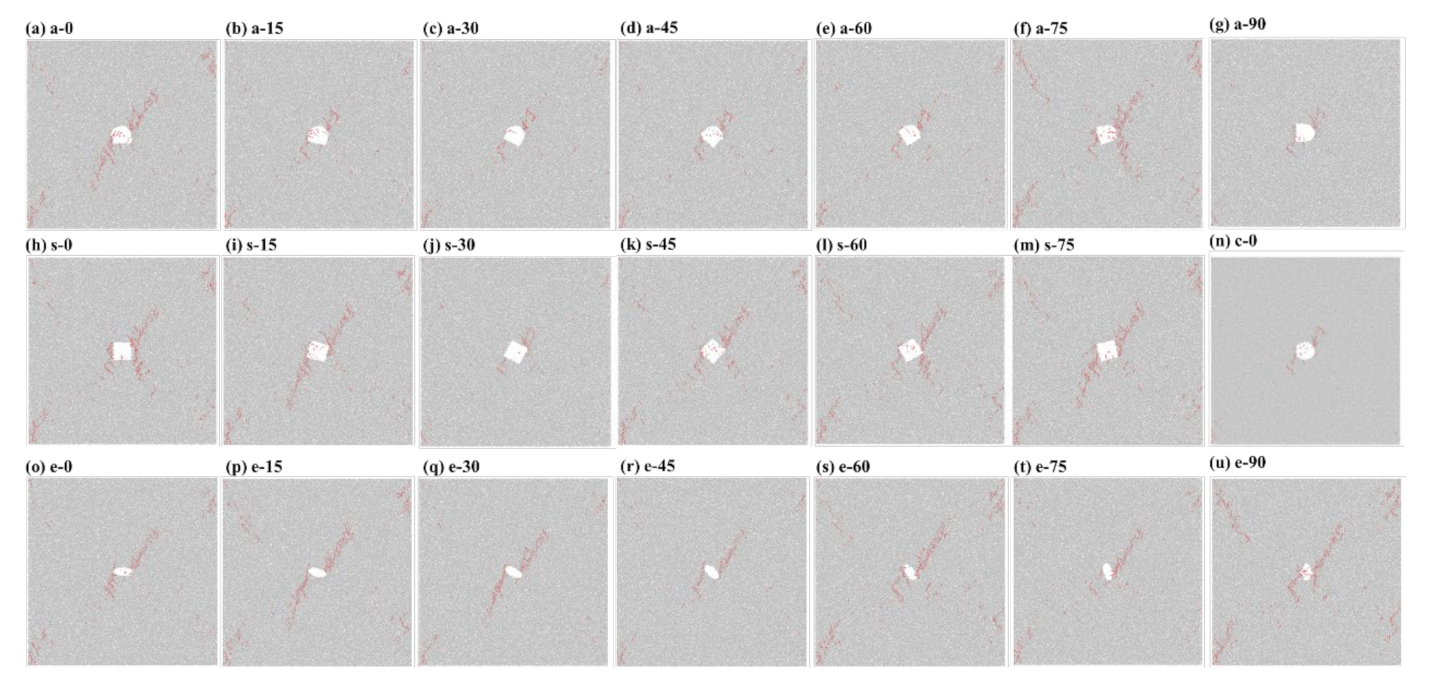
Figure 10.
Ultimate failure images of pre-holed specimens under coupled biaxial loading and unloading conditions.
Figure 10.
Ultimate failure images of pre-holed specimens under coupled biaxial loading and unloading conditions.
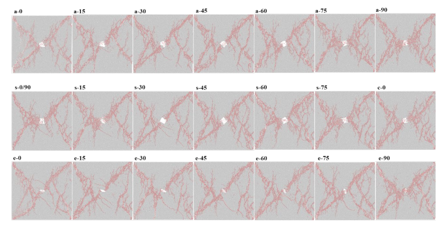
Figure 11.
Fractal dimensions of crack distributions in pre-holed specimens at the ultimate failures under coupled biaxial loading and unloading condition for (a) all specimens and (b) the specimens with different shapes of holes with the same inclination angle.
Figure 11.
Fractal dimensions of crack distributions in pre-holed specimens at the ultimate failures under coupled biaxial loading and unloading condition for (a) all specimens and (b) the specimens with different shapes of holes with the same inclination angle.

Table 1.
Microscopic parameters of granite numerical specimens.
| Microscopic Parameters | Values |
|---|---|
| Minimum particle radius, Rmin (mm) | 0.25 |
| Maximum particle radius, Rmax (mm) | 0.415 |
| Particle size ratio, Rmax/Rmin | 1.66 |
| Bulk density, ρ (kg/m3) | 2604 |
| Particle contact modulus, Ec (GPa) | 20 |
| Ratio of normal to shear stiffness of the particle, kn/ks | 1.7 |
| Parallel-bond modulus, c (GPa) | 20 |
| ns | 1.7 |
| Particle friction coefficient, μ | 0.5 |
| Parallel-bond normal strength, mean σn (MPa) | 85 |
| Parallel-bond normal strength, standard deviation, σsd (MPa) | 8 |
| Parallel-bond shear strength, mean τn (MPa) | 67 |
| Parallel-bond shear strength, standard deviation τsd (MPa) | 6 |
Table 2.
Experimental and numerical macro-mechanical properties of standard cylindrical granite specimens.
Table 2.
Experimental and numerical macro-mechanical properties of standard cylindrical granite specimens.
| Parameter | Experimental Tests | Numerical Tests | Errors (%) |
|---|---|---|---|
| Density (kg/m3) | 2604 | 2604 | - |
| Young’s modulus (GPa) | 33.14 | 32.92 | 0.66 |
| Poisson’s ratio | 0.21 | 0.21 | - |
| Uniaxial compressive strength | 126.59 | 126.68 | 0.07 |
Table 3.
Strength parameters of numerical specimens containing different prefabricated holes.
| Specimen | σucs (MPa) | σbcs (MPa) | σ(ucs + bcs)/2 (MPa) | σbu (MPa) | σls (MPa) |
|---|---|---|---|---|---|
| a-0 | 130.50 | 182.97 | 156.74 | 165.85 | 14.50 |
| a-15 | 129.08 | 183.73 | 156.41 | 166.12 | 14.94 |
| a-30 | 128.95 | 181.25 | 155.10 | 165.48 | 14.64 |
| a-45 | 131.90 | 182.53 | 157.22 | 166.02 | 15.11 |
| a-60 | 135.10 | 184.91 | 160.01 | 168.28 | 15.25 |
| a-75 | 134.43 | 184.46 | 159.45 | 166.07 | 13.83 |
| a-90 | 128.86 | 184.28 | 156.57 | 163.39 | 16.59 |
| s-0 | 127.98 | 180.00 | 153.99 | 162.63 | 14.76 |
| s-15 | 126.01 | 184.82 | 155.42 | 161.95 | 13.87 |
| s-30 | 128.54 | 185.12 | 156.83 | 164.90 | 16.19 |
| s-45 | 130.25 | 183.07 | 156.66 | 164.80 | 14.47 |
| s-60 | 130.03 | 190.17 | 160.10 | 168.23 | 14.41 |
| s-75 | 126.57 | 185.00 | 155.79 | 162.81 | 15.81 |
| s-90 | 127.98 | 180.00 | 153.99 | 162.63 | 14.76 |
| c-0 | 135.05 | 187.41 | 161.23 | 169.87 | 15.71 |
| e-0 | 131.07 | 198.32 | 164.70 | 171.54 | 15.13 |
| e-15 | 142.17 | 189.59 | 165.88 | 171.41 | 14.02 |
| e-30 | 128.85 | 189.93 | 159.39 | 168.52 | 16.29 |
| e-45 | 132.78 | 190.79 | 161.79 | 169.89 | 15.82 |
| e-60 | 137.41 | 196.86 | 167.14 | 175.41 | 13.47 |
| e-75 | 136.04 | 201.52 | 168.78 | 178.60 | 14.78 |
| e-90 | 145.61 | 203.18 | 174.40 | 182.17 | 14.55 |
Publisher’s Note: MDPI stays neutral with regard to jurisdictional claims in published maps and institutional affiliations. |
© 2022 by the authors. Licensee MDPI, Basel, Switzerland. This article is an open access article distributed under the terms and conditions of the Creative Commons Attribution (CC BY) license (https://creativecommons.org/licenses/by/4.0/).
Share and Cite
MDPI and ACS Style
Zhou, Z.; Pi, Z.; Jing, Y.; Wang, S. Responses of Pre-Holed Granite under Coupled Biaxial Loading and Unloading Stress Condition. Minerals 2022, 12, 372. https://doi.org/10.3390/min12030372
AMA Style
Zhou Z, Pi Z, Jing Y, Wang S. Responses of Pre-Holed Granite under Coupled Biaxial Loading and Unloading Stress Condition. Minerals. 2022; 12(3):372. https://doi.org/10.3390/min12030372
Chicago/Turabian StyleZhou, Zilong, Zizi Pi, Yue Jing, and Shaofeng Wang. 2022. "Responses of Pre-Holed Granite under Coupled Biaxial Loading and Unloading Stress Condition" Minerals 12, no. 3: 372. https://doi.org/10.3390/min12030372
Note that from the first issue of 2016, this journal uses article numbers instead of page numbers. See further details here.