
Study on the Mining Effect and Optimal Design of Longwall Full Mining with Paste Partial Filling

1
College of Safety Science and Engineering, Anhui University of Science and Technology, Huainan 232001, China
2
Beijing Tiandi Huatai Mining Management Co., Ltd., Beijing 100013, China
3
School of Architecture and Civil Engineering, Liaocheng University, Liaocheng 252000, China
*
Authors to whom correspondence should be addressed.
Minerals 2024, 14(3), 264; https://doi.org/10.3390/min14030264
Submission received: 17 January 2024
/
Revised: 21 February 2024
/
Accepted: 29 February 2024
/
Published: 1 March 2024
(This article belongs to the Section Environmental Mineralogy and Biogeochemistry)
Abstract
:Various methods of longwall full mining with partial filling have been extensively researched to satisfy the specific mining needs of pressurized-coal and residual-coal resources. This study introduces three longwall partial-filling-mining techniques: room–pillar filling mining, parallel-strip filling mining, and vertical-strip filling mining. Numerical simulations are employed to evaluate the efficacy of these methods. The findings indicate that vertical-strip filling mining results in minimal surface deformation and a more uniform distribution of displacements. In practical operations, the effectiveness of filling largely depends on the choice of filling technology and materials. The research further includes an optimization analysis of the filling technology, emphasizing the composition of the coal-gangue-paste filling system and the refinement of its components. Additionally, the study aims to explore the optimization analysis of filling materials, specifically focusing on performance-optimization methods. The experimental results illustrate that optimizing the filling materials can enhance the performance of filling paste, improving both early-stage and long-term compressive strength. Moreover, the paper examines the quantitative characterization of paste-filling-mining subsidence at various stages in conjunction with theoretical knowledge. Subsequently, mining-subsidence-control measures are recommended to address the primary deformation factors across different stages. Through an in-depth examination of filling-method designs, enhancements in filling technology, and predictions regarding filling-mining subsidence, this research offers valuable insights for optimizing longwall partial-filling-mining methods.
1. Introduction
Filling mining can not only increase the coal-recovery rate but also prevent surface subsidence, improving the safety of mining operations. The industry encounters challenges such as insufficient filling materials and low filling efficiency, impeding the broad implementation of filling-mining technology [1,2,3,4,5]. Enhancing the efficiency and reducing the costs of filling mining in coal mines present pivotal research problems. Partial filling mining emerges as a solution by minimizing the filling-material quantity and related expenses without compromising the intended filling outcome [6,7,8]. Exploring the optimal filling outcome within the context of partial filling mining demands further scrutiny.
Partial mining is primarily categorized into room-and-pillar mining and strip mining. Room-and-pillar mining is commonly practiced in countries such as the United States, Australia, India, South Africa, and certain Chinese coal mines. In contrast, strip mining is more prevalent in European coal mining nations and China [9,10]. During the 1970s, Australia and South Africa introduced a short-wall continuous-shearer equipment for coal mining and devised their own coal mining techniques based on the room-and-pillar layout [11,12]. These approaches, known as the Wongawilli mining method and the Sigma mining method, respectively, proved to be successful and yielded significant economic advantages [13].
Drawing upon the Wongawilli mining method, Chinese scholars have autonomously pioneered short-wall block-type green mining technology. This innovative approach effectively tackles challenges associated with pressurized-coal deposits, irregular block layouts, and the presence of structures above the coal seam [14]. Expanding on this work, Tan et al. [15] proposed a strip Wongawilli mining method utilizing strip-coal-roadway layouts, resulting in heightened productivity and efficiency facilitated by continuous-mining technology. This method introduces a novel strategy for reducing subsidence in mining operations near structures [16,17].
Strip mining, a prevalent method in coal extraction utilized in China under structures, bodies of water, and railroad tracks, has been vital in overcoming significant technical obstacles related to coal-pillar recovery and subterranean gangue treatment. Research by Zhang et al. [18,19] explored the viability of substituting strip-coal pillars with broken gangue and investigated the patterns of roof displacement. Likewise, Chen et al. [20,21] conducted a comprehensive study on the scientific and practical aspects of replacing strip-coal pillars beneath residential areas with filling paste. Sunny Murmu et al. [22] used FLAC3D to evaluate and analyze the vertical stress and material failure mode in and around the longwall working face. Their research involved observing the temporal and spatial patterns of strata movement after implementing replacement mining and confirming the enduring stability of the filled areas.
In practical operations, the effectiveness of filling in coal mining largely depends on the technology and performance of the filling materials [23,24,25,26,27,28]. Coal-mine filling practices involve various types of materials, including bulk materials like raw gangue, coal-gangue paste, and high-water-content materials [3,29,30,31]. Notably, coal-gangue-paste filling technology is a filling method developed over many years in the field of coal mining and is receiving increasing attention, attributed to its advantageous fluidity and mechanical characteristics [23,32,33]. The origin and quality of the coal-gangue filling paste, along with the proportion of raw materials used, significantly influence the overall performance of the filling paste [34,35]. Specifically, the particle-size distribution of coal gangue plays a critical role in structuring the filling material [36], while the size of the fly ash particles impacts the flow and setting properties of the paste [37]. Moreover, the ratio of the cementing agent directly affects the ultimate strength of the filling-paste mixture [38].
Notably, extensive studies have been conducted by researchers on filling-mining and partial-mining practices tailored to the specific requirements of pressurized-coal and residual-coal resources, such as triangular coal. With a primary focus on cost reduction and the assurance of safe and efficient operations, this study highlights longwall partial filling mining as a promising strategy. Despite this focus, there has been a lack of comparative research on the effectiveness of various longwall partial-filling-mining methods. Drawing from current practices in filling mining, partial mining, and the N00-mining approach, this study aims to enhance the efficiency of filling mining by introducing three longwall partial-filling-mining technologies. Using numerical simulation, the study examines the mining outcomes of these methods. By integrating practical knowledge, enhancements have been made to the paste filling system and filling materials, resulting in significant and substantial research findings.
2. Implementation Method of Different Longwall Partial Filling Mining
2.1. Longwall Room–Pillar Filling-Mining Method
Based on the existing mining practices or academic thoughts such as partial mining of room–pillar and structural filling, a method of room–pillar filling mining according to longwall mining is summarized. The roadway layout is shown in Figure 1. The working face adopts backward mining and U-shaped ventilation, and no interval coal pillar is left. In order to ensure that the immediate roof does not break, the filling pier column is arranged behind the longwall-coal-mining face to achieve long-term stable bearing.
2.2. Longwall Parallel-Strip-Filling-Mining Method
Based on the existing strip mining methods, replacement filling, and other mining practices or academic ideas, a parallel-strip-filling-mining method arranged in accordance with longwall mining is summarized. The roadway layout is shown in Figure 2. U-shaped ventilation is adopted, and the filling strip is parallel to the working face to achieve non-pillar mining. The mining design principle also ensures the long-term stability of the immediate roof and the filling strip.
2.3. Longwall Vertical-Strip-Filling-Mining Method
Similar to the parallel-strip filling mining method, U-shaped ventilation is used to realize no-pillar mining. The difference is that the filling strip is perpendicular to the working face, and the roadway layout is shown in Figure 3. The mining design principle ensures that the immediate roof does not collapse and that there is long-term stability of the filling strip.
2.4. Stability Conditions of Longwall Partial Filling Mining
For the three longwall partial-filling-mining methods proposed in this paper, in order to maintain sufficient filling working space or reasonable filling spacing, the empty roof distance of the immediate roof should be less than the initial caving step. In initial mining, the immediate roof can be regarded as a double-ended fixed beam supported by coal walls and coal pillars at both ends. The initial caving step of the immediate roof is as follows [39,40,41]:
In the formula, —initial collapse step distance, m; —immediate roof thickness, m; —tensile strength of immediate roof strata, MPa; —the uniform load density shown by the immediate roof rock beam.
According to the parameters such as the design size of the room and column filling pier and the safety factor requirements, the compressive strength of the in situ filling body is calculated according to the following formula [7]. That is
In the formula, —the average volume weight of the overlying strata, MN/m3; H—buried depth, m; and are the width and height of the filling body, m; is the short-side and long-side spacing of the filling body, m; is the safety factor, and generally 1.5~2.0 times the safety factor is needed.
According to the strength formula of Hustrulid [42], the relationship between the strength of laboratory backfill samples and the in situ strength of backfill can be established:
In the formula, —filling body sample uniaxial compressive strength, MPa; D—the diameter or side length of the filling body sample; L—limit size of the filling body sample.
In summary, the compressive strength of the laboratory filling body sample that meets the filling design of longwall room–pillar filling mining can be obtained:
According to the design principle of parallel-strip filling, the load of the filling paste is calculated according to the most dangerous state, and, as such, all the weight of the overlying strata is borne by the filling strip. According to the theory of ultimate strength, the strength-calculation formula of the filling body sample in the laboratory can also be deduced:
In the formula, We—mining strip width, m; Wp—filling strip width, m.
In addition, the strength of the vertical filling strip can be calculated according to the principle of the parallel-strip filling method.
3. Mining Effect of Different Longwall Full Mining with Partial Filling
3.1. Construction of Numerical Model
Numerical simulation of the Yangjia Village coal mine located in western China was conducted. The mining area, known as the 22 mining area, covers an area of 1629.5 m × 4132.3 m. The coal seam in this area has an average thickness of approximately 4 m and is buried at an average depth of about 100 m. The dip angle of the coal seam ranges from 1° to 5°, with an average of 3°. The coal seam has a simple structure without any water or gas presence. It is important to note that Yangjiacun Coal Mine was solely used as the engineering background for indoor testing purposes. The fundamental mechanical parameters of the rock strata in the mining area are presented in Table 1.
In this paper, according to the basic mechanics of an experiment with coal rock in a coal mine, the simulated rock strata are reasonably assigned. The three-dimensional calculation model established in this simulation is shown in Figure 4. The length (x), width (y), and height (z) are 240 m, 120 m, and 134 m, respectively. The displacement constraints are imposed on the surrounding and bottom surfaces of the model, and the upper boundary is free. The simulation range is half of the mining range in tendency.
In the mining process, the surface’s vertical- and horizontal-displacement-monitoring lines and the maximum- and minimum-principal-stress-monitoring lines inside the rock layer are set up, and the line layout is shown in Figure 5. A total of two survey lines are arranged. Among them, the survey line 1 is arranged on the top of the 1-layer conglomerate. The coordinate of the survey line is Y = 10. The X direction of the measuring point is set every 10 m to monitor the horizontal and vertical displacement of the surface. The measuring line 2 is arranged at the interface of the 5th layer with the 6th layer. The coordinate of the measuring line is Y = 10, and the measuring point is set every 10 m or 15 m in the X direction to monitor the maximum and minimum principal stress of the unit.
3.2. Numerical-Simulation-Results Analysis
The mining methods are room–pillar filling, parallel-strip filling, and vertical-strip filling. The three filling-strip-structure plans are shown in Figure 6 to ensure that the plane-filling rates are equal. According to the numerical calculation results, the stress and displacement information of the monitoring points are obtained.
3.2.1. Stress Distribution Analysis
Figure 7 shows the maximum- and minimum-principal-stress nephograms of the three mining methods when the model is balanced. It can be clearly seen that the maximum principal stress of these three mining methods is roughly manifested as the trend of stress increase near the center of the goaf, and the minimum principal stress is roughly manifested as the trend of stress decrease near the center of the goaf, which is that the value of is becoming larger and larger, indicating that the closer an area is to the middle of the goaf, the more prone it is to instability and failure of the rock stratum.
The stress nephograms in Figure 7 reveal the relationship between stress distribution and the center of the goaf. Additionally, Figure 8 provides specific values and locations of the maximum and minimum principal stresses. The maximum principal stress of room-and-pillar filling is 1.99 MPa, which is located at X = 90 m, and offsets the center of mining. The minimum principal stress is 0.56 MPa, which is located at X = 140 m, and also offsets the center of mining. The maximum principal stress of parallel-strip filling is 1.94 MPa, which is located at X = 80 m, and the center of offset mining. The minimum principal stress is 0.66 MPa, which is located at X = 140 m, and the center of offset mining. The maximum principal stress of vertical-strip filling is 1.88 MPa, which is located at X = 90 m, and the center of offset mining. The minimum principal stress is 1.30 MPa, which is located at X = 140 m, and the center of offset mining.
Through Figure 7 and Figure 8, it can be seen that the maximum principal stress and the minimum principal stress of the three longwall partial-filling-mining methods all show a symmetrical distribution trend. The stress distribution of room–pillar filling mining is close to that of parallel-strip filling mining. The maximum principal stress of vertical-strip filling mining is smaller than those of the other two methods in the same position, and the minimum principal stress is larger than those of the other two methods in the same position, resulting in the minimum value of , so it is more conducive to the resistance of rock strata to failure and instability and the re-balance and stability of mining stress after instability.
3.2.2. Analysis of Displacement Distribution Law
The stress nephograms in Figure 9 reveal the relationship between stress distribution and the center of the goaf. Additionally, Figure 10 and Figure 11 provide specific values and locations of the maximum and minimum principal stresses. Through Figure 9, Figure 10 and Figure 11, the maximum vertical displacement of room–pillar filling is 2.43 cm, and the maximum absolute value of horizontal displacement is 0.68 cm. Both of them offset the mining center, and the vertical displacement and horizontal displacement show obvious symmetrical distribution and anti-symmetrical distribution, respectively. The maximum vertical displacement of parallel-strip filling is 23.17 cm, which is more deviated from the mining center, and the maximum absolute value of horizontal displacement is 1.49 cm. Similarly, the vertical displacement and horizontal displacement almost do not show symmetrical distribution or anti-symmetrical distribution. The maximum vertical displacement of vertical-strip filling is 1.46 cm, which coincides with the mining center. The maximum absolute value of horizontal displacement is 0.59 cm, and there are two extreme centers. The vertical displacement and horizontal displacement show a very obvious symmetrical distribution or anti-symmetric distribution.
In summary, the surface deformation of parallel-strip filling mining is more intense and complex; it is irregular. The surface deformation of room–pillar filling mining is obviously reduced, showing a certain regularity. The surface deformation of vertical-strip filling mining is the smallest, showing obvious regularity, which is conducive to the prediction and prevention of surface subsidence.
From the perspective of construction continuity and operability, there are many independent filling piers in room-and-pillar filling mining, which require many processes such as pouring and supporting, and take a long time. Parallel-strip filling mining can rely on filling support to realize the continuity and automation of filling pouring and support, which is convenient for roof connection. Vertical-strip filling mining only needs to use filling support in the filling area, which greatly reduces the cost of support transformation and upgrading, and the construction continuity can be guaranteed. It is more convenient to carry out the filling process without considering the dip angle of the working face.
4. Filling Process Optimal Design
The above-mentioned comparative study of corresponding numerical simulations is carried out for different mining methods of full mining with partial filling, and the mining method with the best comprehensive mining effect can be selected theoretically. In actual operation, filling technology and filling-material performance are the main factors that determine the filling effect. Therefore, it is necessary to further study the filling technology and filling-material performance.
4.1. Optimization Analysis of Filling System
For a coal mine, the materials employed for paste filling encompass crushed coal gangue, fly ash, ordinary Portland cement, and water. The filling process initiates with the crushing and processing of the gangue. Subsequently, the gangue, fly ash, cement, and water are proportionally mixed and agitated to form a paste-like slurry. This mixture is then conveyed to the goaf through filling pumps and pipelines, establishing a system supported by the filling material and surrounding rock. The paste filling system of a coal mine is generally composed of three parts, namely the filling-material-preparation system, filling-material-conveying system, and working-face-filling system, as shown in Figure 12. The filling-material-preparation system is subdivided into the aggregate-preparation system and mixing system.
- (1)
- Building on research findings, a statistical analysis was conducted on the particle size of undisturbed gangue within the gangue dump. It was observed that a significant proportion of undisturbed gangue had a particle size below 25 mm. In response to this, coal-gangue screening before the breaking process was proposed. This approach greatly enhanced the crushing capacity of the original coal-gangue-crushing system.
- (2)
- To address the current challenges of insufficient coal-gangue supply and vulnerability to adverse weather conditions, a substantial greenhouse for gangue storage has been constructed. This facility aims to ensure there is a continuous supply of gangue for filling purposes, even in adverse conditions.
- (3)
- Recognizing the limited storage capacity of the fly ash silo, which hampers continuous filling, a large-scale fly ash storage and distribution system has been established. This system caters to the requirements of continuous fly ash filling by providing ample storage capacity and efficient distribution mechanisms.
4.2. Optimization Analysis of Filling Materials
4.2.1. Performance-Optimization Method of Coal-Gangue Material
According to the practical experience of our research group, the following measures can be taken in order to improve the activity and purity of the filling materials in the preparation process [43,44,45].
- (1)
- Illustrated in Figure 13, a grating and iron removal device have been incorporated to eliminate impurities such as metal and bamboo waste from the aggregate. This ensures the purity of the final filling aggregate.
- (2)
- During the aggregate-production process, a significant amount of micro-powder measuring less than 0.15 mm is generated. This micro-powder contains notable quantities of SiO2, CaO, and Al2O3. To facilitate the complete recycling of coal gangue, a vacuuming device has been introduced in the aggregate-screening process, as depicted in Figure 13. This micro-powder can replace part of the fly ash and improve the performance of the fly ash.
- (3)
- Figure 13 also demonstrates the possibility of enhancing the performance of coal-gangue aggregate by implementing a particle-shaping process. This involves the inclusion of an eccentric wheel device in the high-fine crusher to remove cement paste adhering to the aggregate’s surface. By employing this approach, the quality of coal-gangue aggregate can be further improved.
4.2.2. Performance-Optimization Effect of Filling Materials
To evaluate the performance-optimization effect of the filling material, this section conducts tests using the original ratio and the optimized materials for the paste filling material. The ratio of the coal-gangue paste, consisting of cement, fly ash, and gangue aggregate, is set at 1:4:6, with a mass concentration of 82%. Two pastes are prepared, one using the materials before optimization and the other using the optimized materials. Both pastes are subjected to the same testing conditions, with measurements taken for slump, stratification, and bleeding rate. Subsequently, they are placed in a standard curing box for curing, and the uniaxial compressive strength of the filling body is tested at different ages (8 h, 1 day, 3 days, 7 days, and 28 days). The test process is illustrated in Figure 14, and the results are presented in Table 2.
According to field-practice experience, the principles for the paste-filling-material ratio are as follows: ① The slump should be greater than 18 cm. ② The stratification of the slurry should be less than 2 cm. ③ The static bleeding rate should be less than 3% to 5%. ④ The initial setting time should be greater than 4 h, and the final setting time should be around 8 h. ⑤ The 8 h strength should be greater than 0.1 MPa. ⑥ The flowability should be greater than 13.5 cm.
The experiments demonstrate that both the slump, stratification, and bleeding rate of the paste materials, before and after optimization, fall within a certain range, meeting the requirements for pipeline transportation. The final setting time for both pastes is controlled between 5 and 6 h, which satisfies the basic requirements for paste filling and mining.
From the test results in Table 2, it can be seen that in the early stage of curing, the 8 h compressive strength of the optimized filling body is higher than that of the coal-gangue paste before optimization, because, from the above test results of pumpability, the final setting time of the optimized paste is lower than that before optimization. From the perspective of long-term strength, the compressive strength of the optimized paste is also higher than that of the coal-gangue paste before optimization. The above comparative tests prove that the optimization measures of filling materials can optimize the performance of filling paste.
5. Source and Treatment of Mining Subsidence
5.1. Source of Mining Subsidence
In the context of backfill mining, surface subsidence primarily encompasses the before-filling roof subsidence , unfilled space , and compressive deformation of the backfill paste , as illustrated in Figure 15. Consequently, the equivalent mining height is expressed as
As depicted in Figure 15a, stable backfill space is imperative during the filling process, necessitating the assurance of roof stability before the completion of the backfilling operations. The roof during periodic fractures can be approximated as a cantilever beam, and the maximum deflection of the cantilever beam under a uniformly distributed load on the rock strata represents the before-filling roof subsidence:
In the formula, is the elastic modulus of the roof, is the moment of inertia of the roof, is the periodic fracture step of the roof, and is the uniformly distributed load on the roof.
As illustrated in Figure 15b, the existing filling technology can basically realize the attached roof filling; however, due to the water-seepage characteristics of the backfill slurry during the curing process, resulting in volume shrinkage, the unfilled space of the backfill is approximated using the seepage rate, which can be experimentally determined in the laboratory:
In the formula, is the seepage rate of the backfill paste; M is the actual mining height.
As demonstrated in Figure 15c, under the influence of overlying-rock-strata load during backfilling, the backfill paste undergoes compressive deformation. The compressive deformation of the backfill is approximated with the peak strain from the uniaxial test on the backfill paste:
In the formula, is the compression ratio of the backfill paste.
The equivalent mining height can be expressed as
And, is simplified to
Based on laboratory experiments, the seepage rate of the backfill paste is approximately in the range of 3% to 5%, and the peak strain from uniaxial tests on the backfill paste is approximately in the range of 1% to 3%. Consequently, the maximum value of the equivalent mining height can be further simplified to
According to on-site experience, it can be known that under paste-filling-mining conditions, the length of the direct roof, which is the aforementioned cantilever beam, is approximately 10 m, and the height is approximately equal to the mining thickness. The elastic modulus of the direct roof can be taken as 10 GPa, and the average bulk density can be taken as 2.5 × 10⁴ N/m3. Therefore, the equivalent mining height of the paste filling can be further expressed as
As shown in Figure 16, using Python, the coal seams with a mining height of 0.5–6 m were analyzed. The equivalent mining height formula derived in this paper was employed to fit the curve between the mining height and the equivalent mining height. Based on the fitted curve, the fitting results are good. Therefore, it is possible to predict the surface subsidence based on the actual mining-height values. Utilizing the predicted results, it is possible to quantitatively study the distribution patterns of the affected rock strata and surface movements in terms of time and space, while also assessing the feasibility of backfill mining.
5.2. Treatment of Mining Subsidence
In accordance with the analysis of roof subsidence sources mentioned above, as illustrated in Figure 15a, the subsidence of the before-filling roof is primarily determined using the lithology of the roof and the filling step. During mining operations, reducing the filling step of the working face and accelerating the filling rate, without affecting normal production, can effectively prevent excessive subsidence of the before-filling roof.
As depicted in Figure 15b, in the design and construction of the backfill paste, attention should be paid to controlling the seepage rate of the backfill material to reduce the unfilled space caused by volume shrinkage after solidification. Considering the addition of substances with different water-absorption and -expansion properties, further optimizing the formulation of the backfill slurry can minimize both seepage rates and volume shrinkage post-solidification.
As shown in Figure 15c, the compression of the backfill material is primarily determined using the mechanical properties of the filling material. By studying the performance of various filling materials and applying scientific proportioning methods, it is possible to design the optimal mixture. This not only controls the filling costs but also minimizes the compression of the filling material.
Additionally, strengthening geological exploration is essential. When encountering special geological conditions, such as a fractured or faulted roof, advanced support and reinforcement should be implemented in these specific areas. This precaution helps prevent significant impact on the filling rate due to severe collapses in those regions.
6. Conclusions
- Based on the layout of the longwall working face, the author proposes three longwall partial filling methods: room–pillar, parallel strip, and vertical strip. Three kinds of longwall full mining with partial filling methods can realize non-pillar mining and U-shaped ventilation. According to the layout characteristics of the longwall partial filling method, combined with the ultimate strength theory and empirical formula, the corresponding uniaxial compressive strength calculation formula of the laboratory filling sample was obtained. Under the condition of ensuring the same filling rate, the numerical simulation of the mining effect of three longwall full mining with partial filling methods is found out. The value of in vertical-strip filling mining is the smallest, which is more beneficial to the stability of the rock strata against failure and the re-equilibrium stability of mining stress after instability. The surface deformation of vertical-strip filling mining is the smallest, showing obvious regularity, which is conducive to the prediction and prevention of surface subsidence.
- In terms of filling materials, the inclusion of grating and iron removal devices ensures the purity of the filling aggregate by eliminating impurities. The recycling of micro-powder generated during the aggregate-production process reduces the need for additional cementitious materials. Additionally, the particle-shaping process enhances the performance of coal-gangue aggregate. In terms of the filling process, optimizing the preparation, conveying, and construction of filling materials ensures compliance with pipeline transportation requirements and guarantees the stability and durability of the filling body. Experimental results demonstrate that the optimized filling material exhibits higher compressive strength during the early curing stage compared to the coal-gangue paste before optimization. Furthermore, the optimized paste shows higher long-term strength than the coal-gangue paste. Comparative tests on pumpability confirm that the optimization measures of filling materials effectively enhance the performance of the filling paste.
- Mining subsidence in backfill mining involves complex factors, including pre-filling roof subsidence, unfilled space, and the compressive deformation of the backfill paste. Treatment strategies include reducing the filling steps and accelerating rates to prevent excessive pre-filling roof subsidence. Attention during backfill-paste design includes controlling seepage rates, optimizing formulations, and considering water-absorbing substances to minimize volume shrinkage. Mechanical properties of the filling material influence compression, with scientific proportioning methods aiding in creating cost-effective mixture designs. By measuring the actual mining height, it is possible to predict the surface subsidence after paste mining and evaluate the feasibility of paste mining.
Author Contributions
All the authors contributed to publishing this paper. Writing—original draft, visualization and resources, Y.Z.; writing—review and editing, funding acquisition and supervision, C.W.; formal analysis and data curation, C.L.; investigation and project administration, J.W.; validation and software, B.Z. All authors have read and agreed to the published version of the manuscript.
Funding
This research was financially supported by the funding of National Natural Science Foundation of China (52304198); Anhui Provincial Key Research and Development Project (2022m07020006) and Anhui University Excellent Scientific Research and Innovation Team Project (2022AH010051).
Data Availability Statement
All the data in this paper are available from the corresponding author upon request.
Acknowledgments
Special thanks are due to the reviewers and editors of this journal for their valuable suggestions and revisions of the manuscript.
Conflicts of Interest
Jianhang Wang is employees of Beijing Tiandi Huatai Mining Management Co., Ltd. The paper reflects the views of the scientists and not the company.
References
- Cui, B.; Feng, G.; Bai, J.; Xue, G.; Wang, K.; Shi, X.; Wang, S.; Wang, Z. Failure Characteristics and the Damage Evolution of a Composite Bearing Structure in Pillar-Side Cemented Paste Backfilling. Int. J. Miner. Metall. Mater. 2023, 14, 1524–1537. [Google Scholar] [CrossRef]
- Tikou, B.; Mostafa, B. Design and Application of Underground Mine Paste Backfill Technology. Geotech. Geol. Eng. 2008, 26, 147–174. [Google Scholar]
- Wang, C.; Shen, B.; Chen, J.; Tong, W.; Jiang, Z.; Liu, Y.; Li, Y. Compression Characteristics of Filling Gangue and Simulation of Mining with Gangue Backfilling: An Experimental Investigation. Geomech. Eng. 2020, 20, 485–495. [Google Scholar]
- Wang, C.; Jiang, N.; Shen, B.; Sun, X.; Zhang, B.; Lu, Y.; Li, Y. Distribution and Evolution of Residual Voids in Longwall Old Goaf. Geomech. Eng. 2019, 19, 105–114. [Google Scholar]
- Daehyeon, K.; Kyungho, P. Evaluation of the Grouting in the Sandy Ground Using Bio Injection Material. Geomech. Eng. 2017, 12, 739–752. [Google Scholar]
- Andre, Z.; Anderson, W. Subsidence Over Room and Pillar Retreat Mining in a Low Coal Seam. Int. J. Min. Sci. Technol. 2019, 29, 51–57. [Google Scholar]
- Wang, C.; Lu, Y.; Shen, B.; Li, Y.; Liang, Y. Design and Monitoring of CPB Replacement Mining RSCP: A Case Study in China. Energy Sour. Part A Recovery Util. Environ. Effects 2021, 43, 80–95. [Google Scholar] [CrossRef]
- Wang, Q.; Su, X.; Jin, Y.; Sun, C.; Yu, S.; Zhao, W. Experimental Investigation of Reservoir Fluid Interlayer Crossflow through Fracture during the Drainage Stage of Coal Measure Gas Well. Nat. Resour. Res. 2023, 16, 1283–1298. [Google Scholar] [CrossRef]
- Heritage, Y. Mechanics of Rib Deformation Observations and Monitoring in Australian Coal Mines. Int. J. Min. Sci. Technol. 2019, 29, 119–129. [Google Scholar] [CrossRef]
- Chabukdhara, M.; Singh, O.P. Coal Mining in Northeast India: An Overview of Environmental Issues and Treatment Approaches. Int. J. Coal Sci. Technol. 2016, 3, 87–96. [Google Scholar] [CrossRef]
- Holland, C.T. The Strength of Coal In Mine Pillars. In Proceedings of the 6th Symposium on Rock Mechanics, Rolla, MO, USA, 28 October 1964. [Google Scholar]
- Nesterov, M.P. An Engineering Method of Determining the Loads on Safety and Isolated Pillars. Sov. Min. Sci. 1969, 5, 489–493. [Google Scholar] [CrossRef]
- Guo, W.; Xu, F. Numerical Simulation of Overburden and Surface Movements For Wongawilli Strip Pillar Mining. Int. J. Min. Sci. Technol. 2016, 26, 71–76. [Google Scholar] [CrossRef]
- Liu, J.; Sui, W.; Zhao, Q. Environmentally Sustainable Mining: A Case Study of Intermittent Cut-and-Fill Mining Under Sand Aquifers. Environ. Earth Sci. 2017, 76, 562. [Google Scholar] [CrossRef]
- Tan, Y.; Guo, W.; Bai, E.; Yan, D. The Height of Fractured Zones Caused by Strip Wongawilli Mining in a Shallow Buried Coal Seam Underlying a Hard Roof. Curr. Sci. 2018, 115, 1387–1392. [Google Scholar] [CrossRef]
- Xu, Y.; Ma, L.; Ngo, I.; Zhai, J. Prediction of the Height of Water-Conductive Fractured Zone Under Continuous Extraction and Partial Backfill Mining Method—A Case Study. Sustainability 2022, 14, 6582. [Google Scholar] [CrossRef]
- Ma, L.; Jin, Z.; Liu, W.; Zhang, D.; Zhang, Y. Wongawilli Roadway Backfilling Coal Mining Method—A Case Study in Wangtaipu Coal Mine. Int. J. Oil Gas Coal Technol. 2019, 20, 342–359. [Google Scholar] [CrossRef]
- Sun, Q.; Zhang, J.; Li, M.; Zhou, N. Experimental Evaluation of Physical, Mechanical, and Permeability Parameters of Key Aquiclude Strata in a Typical Mining Area of China. J. Clean. Prod. 2020, 267, 122109. [Google Scholar] [CrossRef]
- Qiang, Z.; Zhang, J.; Wu, Z.; Chen, Y. Overview of Solid Backfilling Technology Based on Coal-Waste Underground Separation in China. Sustainability 2019, 11, 2118. [Google Scholar]
- Chen, S.; Wang, H.; Wang, H.; Guo, W.; Li, X. Strip Coal Pillar Design Based on Estimated Surface Subsidence in Eastern China. Rock Mech. Rock Eng. 2016, 49, 3829–3838. [Google Scholar]
- Chen, S.; Yin, D.; Cao, F.; Liu, Y.; Ren, K. An Overview of Integrated Surface Subsidence-Reducing Technology in Mining Areas of China. Nat. Hazards 2016, 81, 1129–1145. [Google Scholar] [CrossRef]
- Murmu, S.; Budi, G. Spalling Hazard Occurrence in Longwall Excavation: A Case Study. Min. Metall. Explor. 2023, 40, 1899–1919. [Google Scholar] [CrossRef]
- Wang, C.; Liu, Y.; Hu, H.; Li, Y.; Lu, Y. Study on Filling Material Ratio and Filling Effect: Taking Coarse Fly Ash and Coal Gangue As the Main Filling Component. Adv. Civ. Eng. 2019, 2019, 2898019. [Google Scholar] [CrossRef]
- Jafari, M.; Grabinsky, M. Effect of Hydration on Failure Surface Evolution of Low Sulfide Content Cemented Paste Backfill. Int. J. Rock Mech. Min. Sci. 2021, 144, 104749. [Google Scholar] [CrossRef]
- Mashifana, T.; Sithole, T. Clean Production of Sustainable Backfill Material from Waste Gold Tailings and Slag. J. Clean. Prod. 2021, 308, 127357. [Google Scholar] [CrossRef]
- Nasharuddin, R.; Luo, G.; Robinson, N.; Fourie, A.; Johns, M.L.; Fridjonsson, E.O. Understanding the Microstructural Evolution of Hypersaline Cemented Paste Backfill with Low-Field Nmr Relaxation. Cem. Concr. Res. 2021, 147, 106516. [Google Scholar] [CrossRef]
- Verma, S.K.; Ashish, D.K. Mechanical Behavior of Concrete Comprising Successively Recycled Concrete Aggregates. Adv. Concr. Construct. 2017, 5, 303–311. [Google Scholar]
- Aalianvari, A. Combination of Engineering Geological Data and Numerical Modeling Results to Classify the Tunnel Route Based on the Groundwater Seepage. Geomech. Eng. 2017, 13, 671–683. [Google Scholar]
- Cui, B.; Feng, G.; Bai, J.; Wang, K.; Shi, X.; Wu, H. Acoustic Emission Characteristics and Damage Evolution Process of Backfilling Body–Coal Pillar–Backfilling Body Composite Structure. Bull. Eng. Geol. Environ. 2022, 81, 300. [Google Scholar] [CrossRef]
- Wang, C.; Hu, H.; Zhang, M.; Li, H.; Zhang, G.; Xu, M. Experimental Study on Chemical–Physical Hardening Mechanism of Early Strength of Filling Paste. Geotech. Geol. Eng. 2022, 41, 1715–1724. [Google Scholar]
- Wang, C.; Lu, Y.; Li, Y.; Zhang, B.; Liang, Y. Deformation Process and Prediction of Filling Gangue: A Case Study in China. Geomech. Eng. 2019, 18, 417–426. [Google Scholar]
- Sotiriadis, K.; Hlobil, M.; Viani, A.; Mácová, P.; Vopálenský, M. Physical-Chemical-Mechanical Quantitative Assessment of the Microstructural Evolution in Portland-Limestone Cement Pastes Exposed to Magnesium Sulfate Attack at Low Temperature. Cem. Concr. Res. 2021, 149, 106566. [Google Scholar] [CrossRef]
- Martins, A.C.P.; Franco De Carvalho, J.M.; Costa, L.C.B.; Andrade, H.D.; de Melo, T.V.; Ribeiro, J.C.L.; Pedroti, L.G.; Peixoto, R.A.F. Steel Slags in Cement-Based Composites: An Ultimate Review on Characterization, Applications and Performance. Construct. Build. Mater. 2021, 291, 123265. [Google Scholar] [CrossRef]
- Wilson, J.; Bateman, K.; Tachi, Y. The Impact of Cement on Argillaceous Rocks in Radioactive Waste Disposal Systems: A Review Focusing on Key Processes and Remaining Issues. Appl. Geochem. 2021, 130, 104979. [Google Scholar] [CrossRef]
- Aida, M.L.; Dimitri, F.; Aditya, K. How Do Different Testing Procedures Affect the Rheological Properties of Cement Paste? Cem. Concr. Res. 2020, 137, 106189. [Google Scholar]
- Liu, J.; Li, W.; Zhang, F.; Zhang, X.; Chen, L.; Liu, Y. Optimization and Hydration Mechanism of Composite Cementing Material for Paste Filling In Coal Mines. Adv. Mater. Sci. Eng. 2019, 2019, 3732160. [Google Scholar] [CrossRef]
- Naguleswaran, N.; Nagaratnam, S.; Ryan, L.V. Flow Characteristics of Cemented Paste Backfill. Geotech. Geol. Eng. 2018, 36, 2261–2272. [Google Scholar]
- Cui, B.; Liu, Y.; Guo, H.; Liu, Z.; Lu, Y. Experimental Study on the Durability of Fly Ash-Based Filling Paste in Environments with Different Concentrations of Sulfates. Adv. Mater. Sci. Eng. 2018, 2018, 4315345. [Google Scholar] [CrossRef]
- Brady, B.H.G.; Brown, E.T. Rock Mechanics for Underground Mining; Springer: Berlin/Heidelberg, Germany, 2006. [Google Scholar]
- Baotang, S.; Nick, B. Rock Fracturing Mechanisms Around Underground Openings. Geomech. Eng. 2018, 16, 35–47. [Google Scholar]
- Ning, J.; Wang, J.; Tan, Y.; Zhang, L.; Zhang, L. In Situ Investigations Into Mining-Induced Overburden Failures In Close Multiple-Seam Longwall Mining: A Case Study. Geomech. Eng. 2017, 12, 657–673. [Google Scholar] [CrossRef]
- Hustrulid, W.A. A Review of Coal Pillar Strength Formulas. Rock Mech. 1976, 8, 115–145. [Google Scholar] [CrossRef]
- Djebien, R.; Bouabaz, A.; Abbas, Y.; Ziada, Y.N. A Review on the Effect of Marble Waste on Properties of Green Concrete. Adv. Concr. Construct. 2023, 15, 63–74. [Google Scholar]
- Hosseini, S.A. Seawater Curing Effects on the Permeability of Concrete Containing Fly Ash. Adv. Concr. Construct. 2022, 14, 205–214. [Google Scholar]
- Yoon, Y.-S.; Lee, J.-S.; Min, J.-Y.; Kwon, S.-J. Behavior of Apparent Chloride Diffusion Coefficient of Fly Ash Concrete Under Long-Term Marine Exposure. Adv. Concr. Construct. 2022, 14, 369–380. [Google Scholar] [CrossRef]
Figure 1.
Mining-effect diagram for room–pillar filling. 1—Panel area; 2—working face; 3—filling area; 4—empty area; 5—left lane area; 6—air intake groove; 7—return airflow groove; 8—return airflow downhill; 9—track downhill; 10—belt downhill.
Figure 1.
Mining-effect diagram for room–pillar filling. 1—Panel area; 2—working face; 3—filling area; 4—empty area; 5—left lane area; 6—air intake groove; 7—return airflow groove; 8—return airflow downhill; 9—track downhill; 10—belt downhill.
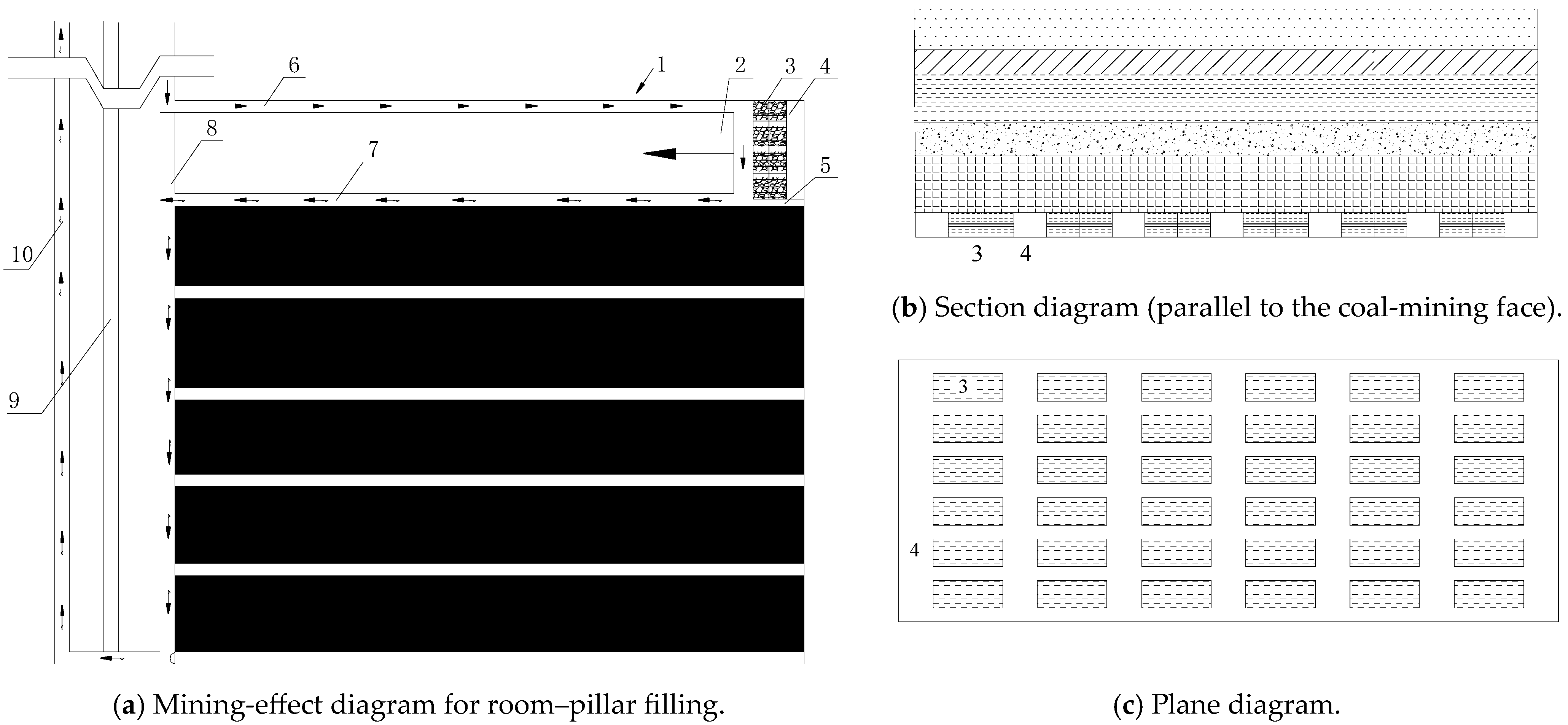
Figure 2.
Mining-system layout for parallel-strip-type filling. 1—Panel area; 2—working face; 3—filling area; 4—empty area; 5—left lane area; 6—air intake groove; 7—return airflow groove; 8—return airflow downhill; 9—track downhill; 10—belt downhill.
Figure 2.
Mining-system layout for parallel-strip-type filling. 1—Panel area; 2—working face; 3—filling area; 4—empty area; 5—left lane area; 6—air intake groove; 7—return airflow groove; 8—return airflow downhill; 9—track downhill; 10—belt downhill.
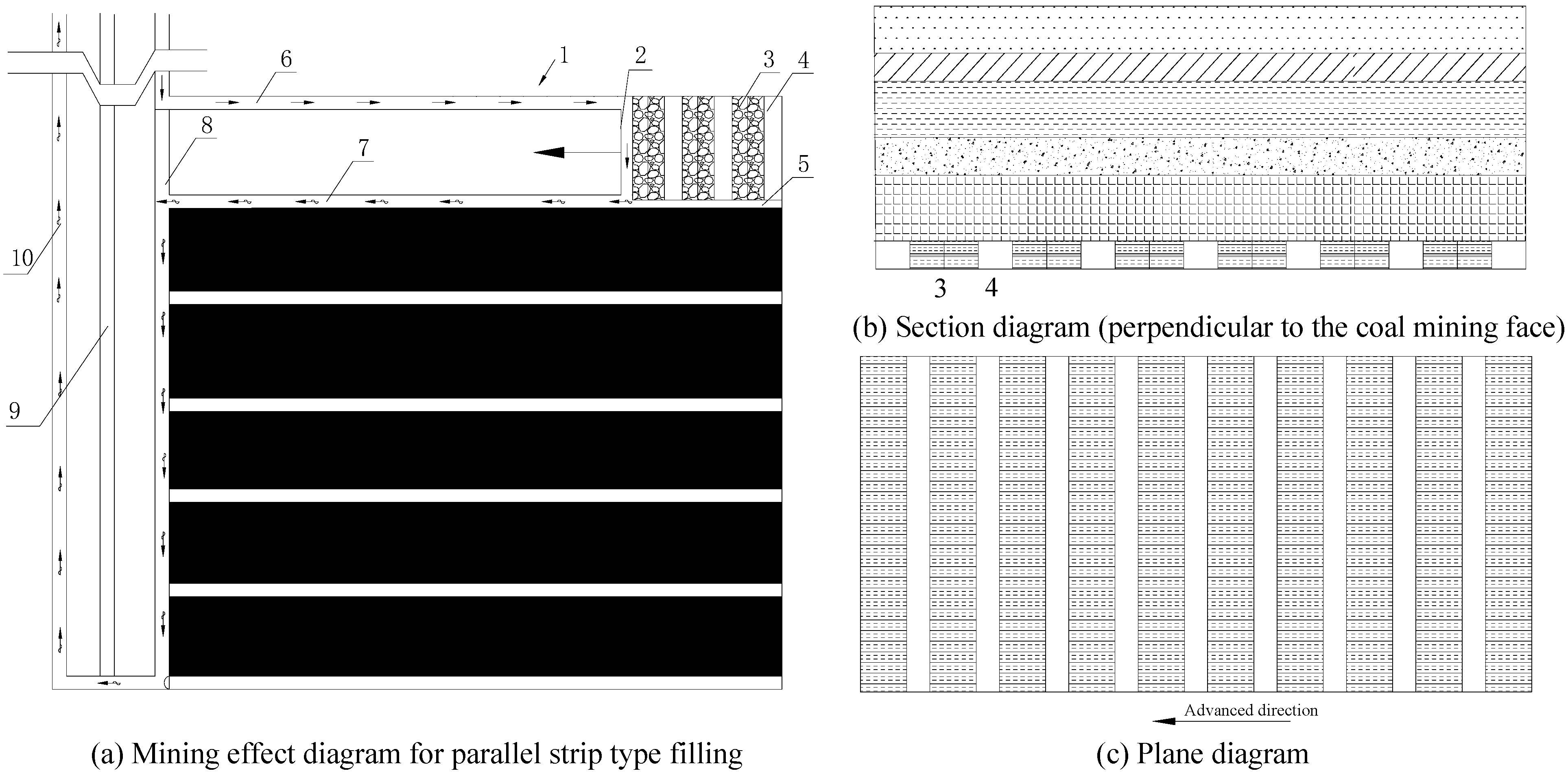
Figure 3.
Mining-system layout for vertical-strip-type filling. 1—Panel area; 2—working face; 3—filling area; 4—empty top area; 5—left lane area; 6—air intake groove; 7—return airflow groove; 8—return airflow downhill; 9—track downhill; 10—belt downhill.
Figure 3.
Mining-system layout for vertical-strip-type filling. 1—Panel area; 2—working face; 3—filling area; 4—empty top area; 5—left lane area; 6—air intake groove; 7—return airflow groove; 8—return airflow downhill; 9—track downhill; 10—belt downhill.
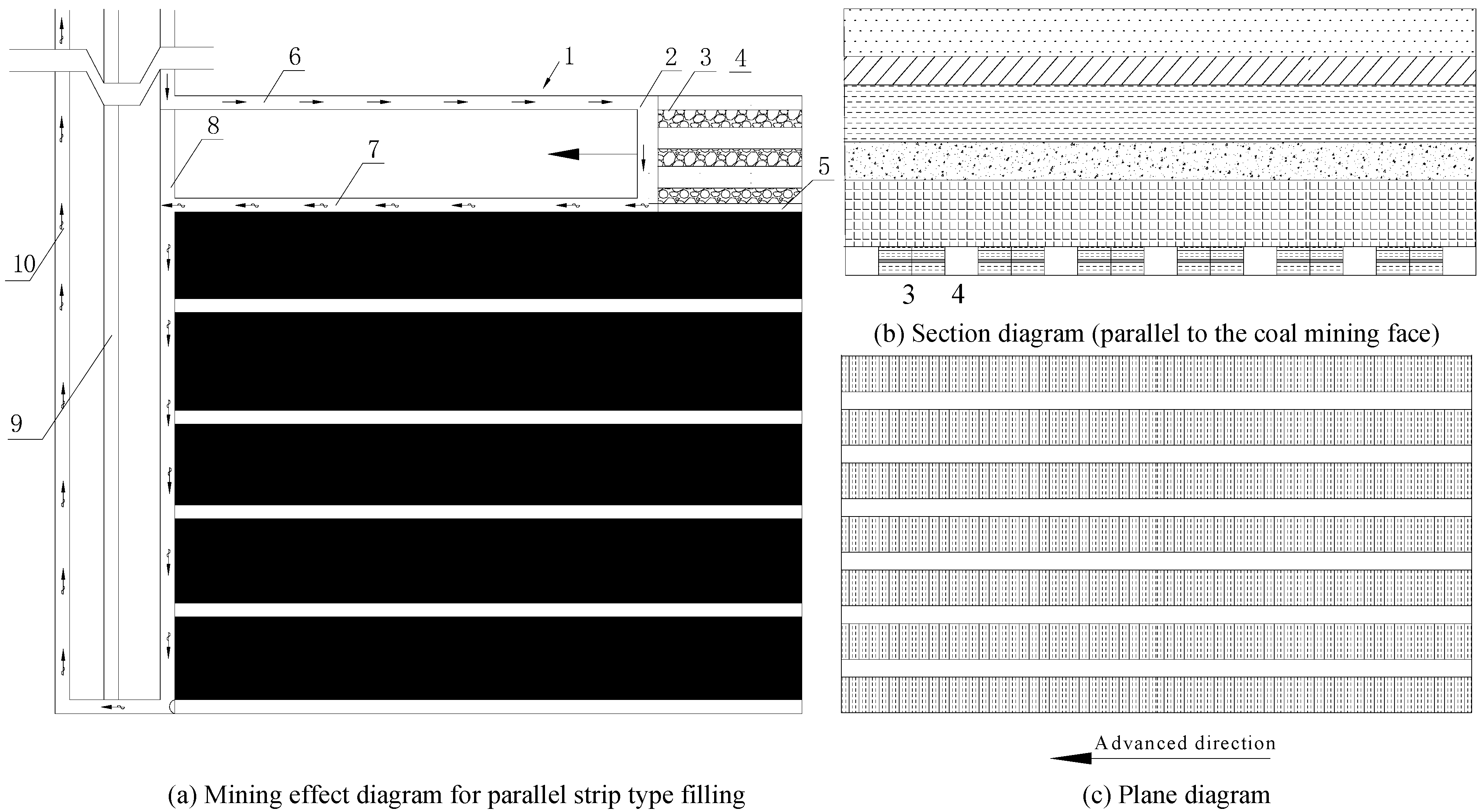
Figure 4.
The numerical-simulation mode.
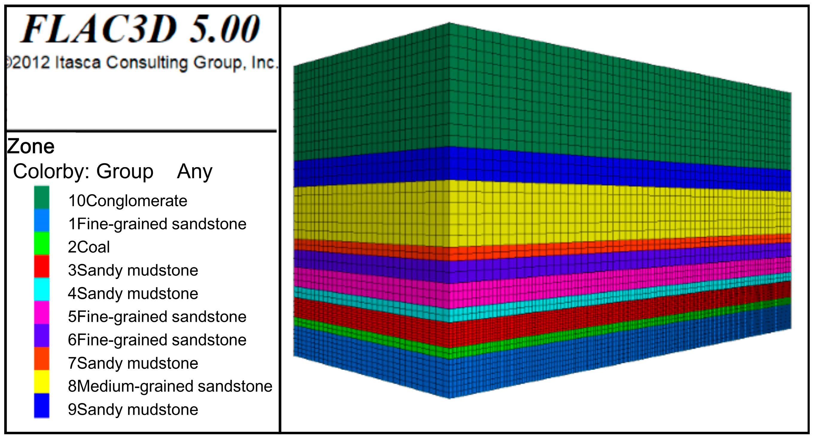
Figure 5.
Layout of mining survey line.

Figure 6.
The diagram of three longwall partial filling methods.

Figure 7.
Maximum–minimum-main-stress cloud map of mining balance.
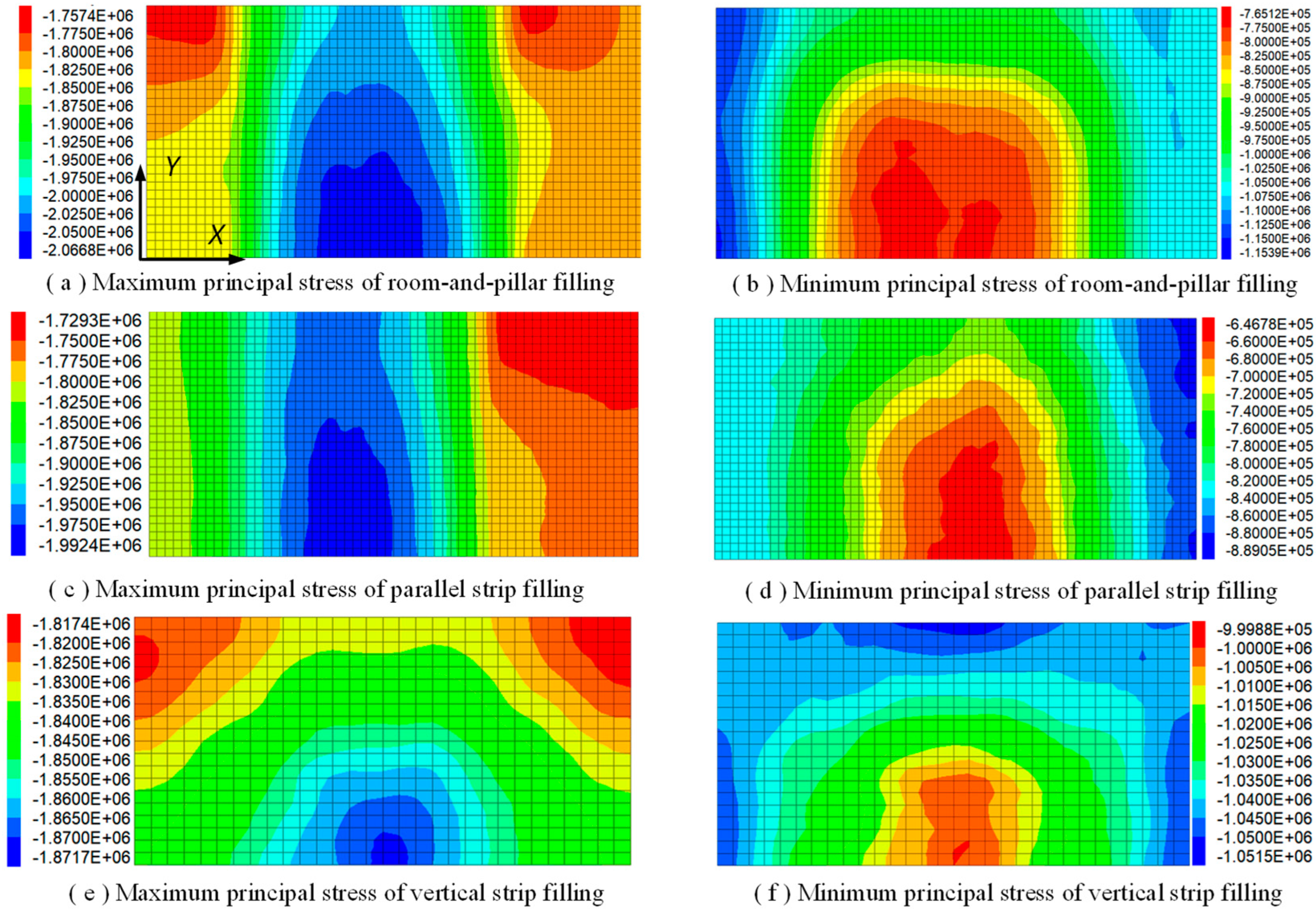
Figure 8.
Main-stress distribution of measuring line at mining balance.
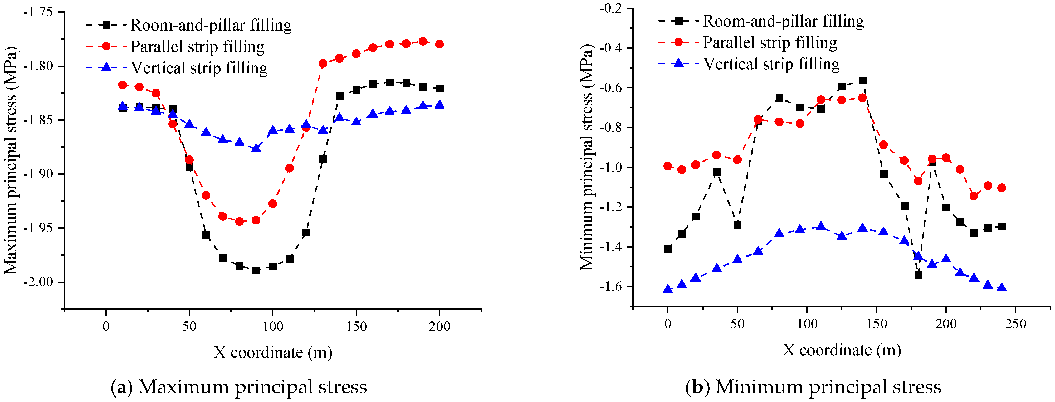
Figure 9.
Vertical–horizontal-displacement cloud map of mining balance.
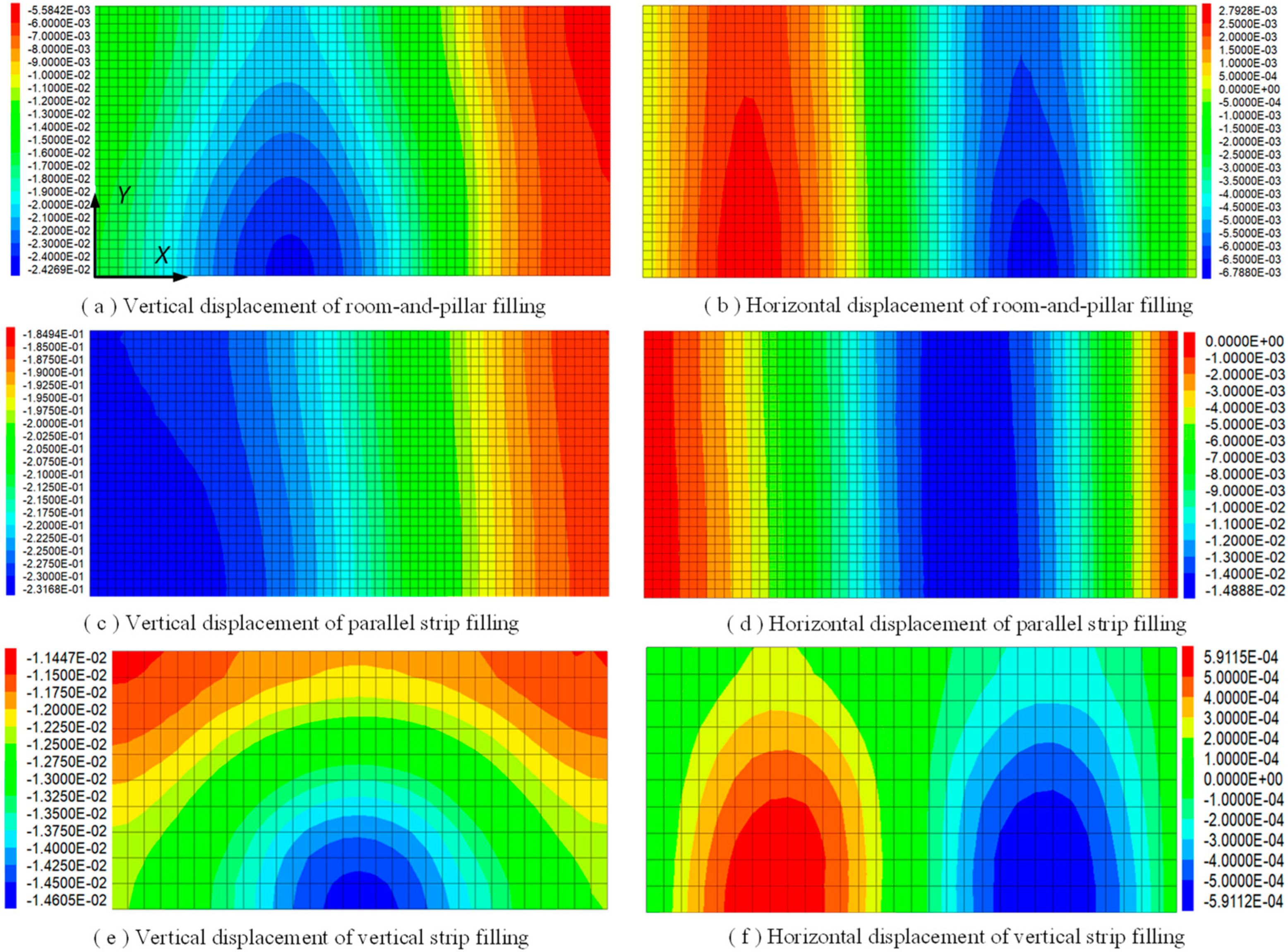
Figure 10.
Vertical-displacement distribution of measuring line during mining balance.
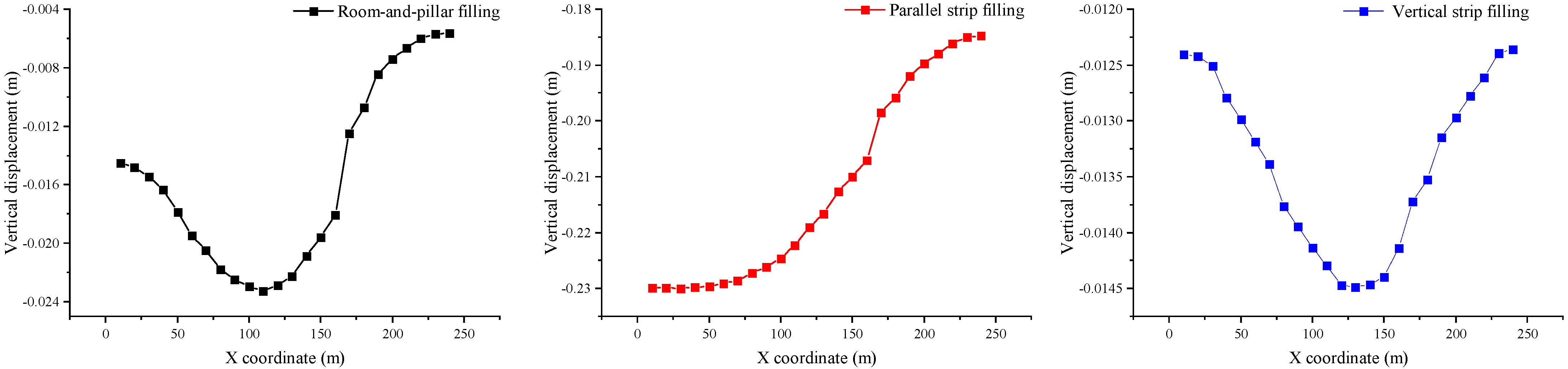
Figure 11.
Horizontal-displacement distribution of measuring line during mining balance.

Figure 12.
Paste-filling-process flow diagram.

Figure 13.
Crushing process of coal-gangue waste in filling mining.
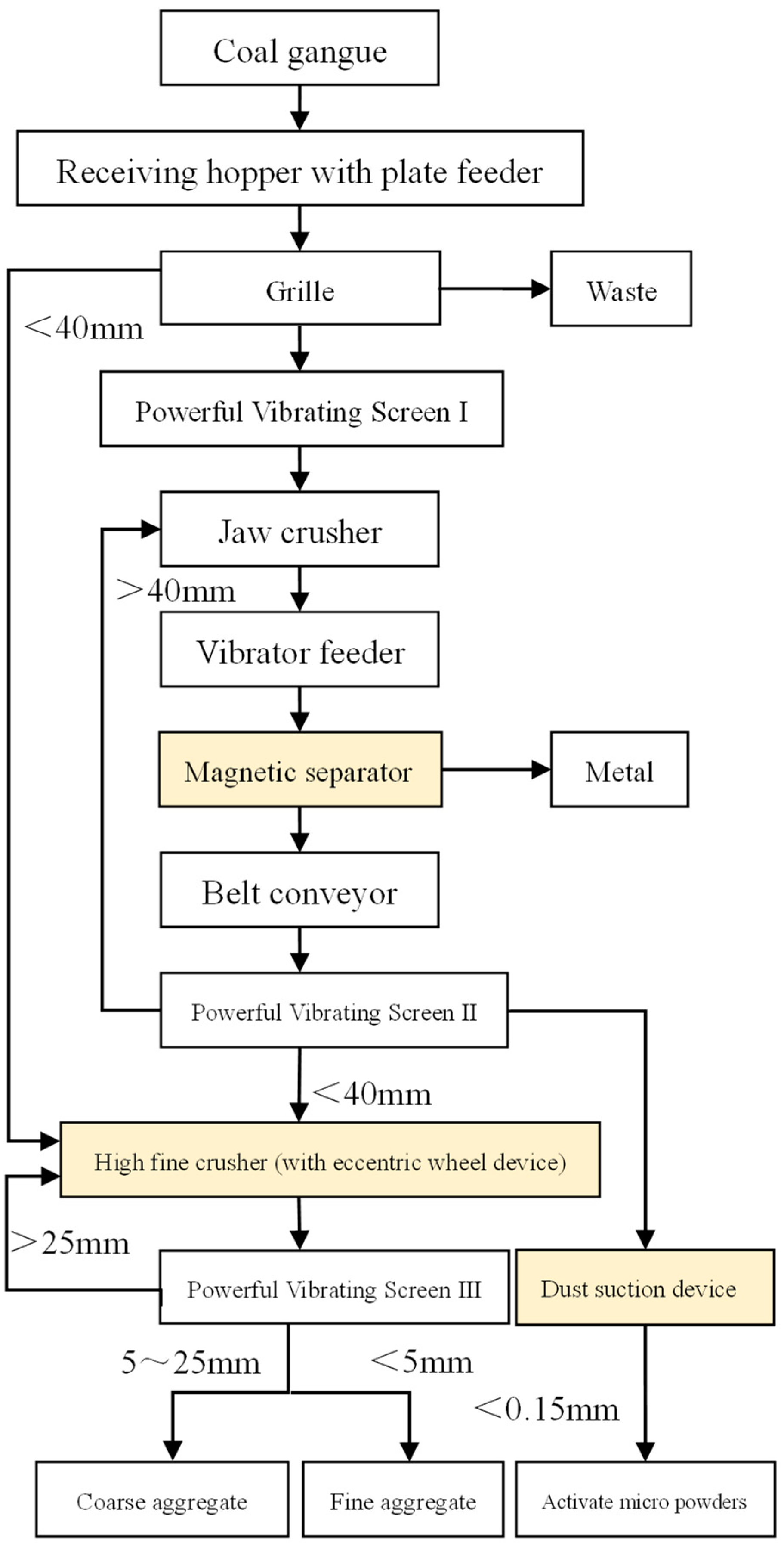
Figure 14.
Preparation process of filling paste.

Figure 15.
Source and control method of paste filling subsidence at different stages.

Figure 16.
Mining-height and equivalent-mining-height fitting curve.


Table 1.
Formation parameters of coal mine.
| ID | Lithology | Thickness /m | Volumetric Force/kN/m3 | Elastic Modulus/GPa | Compressive Strength/MPa | Tensile Strength/MPa | Friction Angle/° | Cohesion /MPa |
|---|---|---|---|---|---|---|---|---|
| 10 | Conglomerate | 44 | 22 | 1.30 | 11.90 | 1.13 | 31 | 1.11 |
| 9 | Sandy mudstone | 12 | 22 | 1.67 | 16.23 | 1.31 | 28 | 1.24 |
| 8 | Medium-grained sandstone | 24 | 24 | 2.83 | 21.23 | 1.90 | 33 | 1.93 |
| 7 | Sandy mudstone | 5 | 20 | 1.67 | 16.23 | 1.33 | 28 | 1.21 |
| 6 | Fine-grained sandstone | 8 | 26 | 3.35 | 28.43 | 2.10 | 33 | 2.14 |
| 5 | Fine-grained sandstone | 9 | 26 | 3.35 | 28.43 | 2.14 | 33 | 2.12 |
| 4 | Sandy mudstone | 5 | 22 | 1.67 | 16.23 | 1.61 | 28 | 1.23 |
| 3 | Sandy mudstone | 9 | 22 | 1.67 | 16.23 | 1.63 | 28 | 1.24 |
| 2 | Coal | 4 | 14 | 1.44 | 10.21 | 1.21 | 30 | 1.02 |
| 1 | Fine-grained sandstone | 14 | 26 | 3.35 | 28.43 | 2.14 | 33 | 2.12 |
Table 2.
Comparison of paste’s pumpability and uniaxial compressive strength.
| Paste Type | Slump/cm | Stratification/cm | Bleeding Rate/% | Fluidity/cm | Compression Strength/MPa | ||||
|---|---|---|---|---|---|---|---|---|---|
| 8 h | 1 d | 3 d | 7 d | 28 d | |||||
| Paste before optimization | 21.3 | 1.6 | 2.7 | 14.2 | 0.14 | 0.33 | 1.31 | 2.59 | 3.23 |
| Paste after optimization | 21.0 | 1.3 | 2.1 | 15.2 | 0.16 | 0.49 | 1.36 | 2.92 | 3.91 |
Disclaimer/Publisher’s Note: The statements, opinions and data contained in all publications are solely those of the individual author(s) and contributor(s) and not of MDPI and/or the editor(s). MDPI and/or the editor(s) disclaim responsibility for any injury to people or property resulting from any ideas, methods, instructions or products referred to in the content. |
© 2024 by the authors. Licensee MDPI, Basel, Switzerland. This article is an open access article distributed under the terms and conditions of the Creative Commons Attribution (CC BY) license (https://creativecommons.org/licenses/by/4.0/).
Share and Cite
MDPI and ACS Style
Zhou, Y.; Wang, C.; Liao, C.; Wang, J.; Zhang, B. Study on the Mining Effect and Optimal Design of Longwall Full Mining with Paste Partial Filling. Minerals 2024, 14, 264. https://doi.org/10.3390/min14030264
AMA Style
Zhou Y, Wang C, Liao C, Wang J, Zhang B. Study on the Mining Effect and Optimal Design of Longwall Full Mining with Paste Partial Filling. Minerals. 2024; 14(3):264. https://doi.org/10.3390/min14030264
Chicago/Turabian StyleZhou, Yongqiang, Changxiang Wang, Changlong Liao, Jianhang Wang, and Baoliang Zhang. 2024. "Study on the Mining Effect and Optimal Design of Longwall Full Mining with Paste Partial Filling" Minerals 14, no. 3: 264. https://doi.org/10.3390/min14030264
Note that from the first issue of 2016, this journal uses article numbers instead of page numbers. See further details here.