

Swelling Stress of Bentonite: Thermodynamics of Interlayer Water in K-Montmorillonite in Consideration of Alteration
1
Graduate School of Environmental, Life, Natural Science and Technology, Okayama University, 3-1-1, Tsushima-naka, Kita-ku, Okayama 700-0082, Japan
2
Institute of Academic and Research, Okayama University, 3-1-1, Tsushima-naka, Kita-ku, Okayama 700-8530, Japan
*
Author to whom correspondence should be addressed.
Minerals 2024, 14(4), 430; https://doi.org/10.3390/min14040430
Submission received: 16 February 2024
/
Revised: 16 April 2024
/
Accepted: 19 April 2024
/
Published: 21 April 2024
(This article belongs to the Special Issue Environmental Mineralogy, 2nd Edition)
Abstract
:The buffer material that makes up the geological disposal system of high-level waste swells by contact with groundwater and seals space with rock mass and fractures in rock mass. The buffer material has a function of mechanical buffer with rock pressure, and swelling stress is important in this case. The alteration of bentonite may occur due to the initial replacement of cations (Na+ ions) in the interlayer with K+ ions upon contact with groundwater, but there are no studies on the swelling stress of K-bentonite. In this study, the author prepared K-montmorillonite samples and obtained thermodynamic data on interlayer water as a function of water content using a relative humidity method. The swelling stress was analyzed based on a thermodynamic model developed in earlier studies and compared with measured data. The activity and the relative partial molar Gibbs free energy of porewater decreased with decreasing water content in the region, below approximately 15%. This behavior significantly differs from that of other ions, such as Na. The swelling stress calculated based on the thermodynamic model and date occurred in the region of high density of 1.9 Mg/m3 with montmorillonite partial density. It was indicated for the first time that K-bentonite scarcely swells under realistic design conditions.
1. Introduction
1.1. Research Background
1.1.1. Overview of Radioactive Waste Disposal
In nuclear power plants, reprocessing plants, fuel fabrication facilities, uranium enrichment facilities, and facilities using radioactive isotopes, various types and forms of radioactive waste are generated due to the operation and maintenance of the facilities, the use of radioactive materials, and the dismantling of the facilities.
In Japan, radioactive waste is classified into two categories: high-level waste, which mainly consists of fission products, and low-level waste. The disposal methods for low-level waste are further classified based on the type of radioactive nuclides, the level of radioactivity, and the place of origin, with the selection of the depth and barriers according to the level of radioactivity. The disposal methods planned include near-surface disposal (trench type) (depth of a few meters), near-surface disposal (concrete pit type) (depth of a few meters to 20 m (less than 50 m)), intermediate depth disposal (deeper than 70 m), and geological disposal (deeper than 300 m). However, among these four disposal methods, the only one currently implemented is the near-surface disposal (concrete pit type) that started in 1992 at the Rokkasho Low-Level Radioactive Waste Disposal Center in Rokkasho-mura, Aomori Prefecture, operated by Japan Nuclear Fuel Limited. Therefore, various research institutions are advancing technical research on each radioactive waste disposal method. Among these disposals, this study focuses on geological disposal.
1.1.2. Geological Disposal System
The safety of the radioactive waste disposal system, with the exception of the near-surface disposal (trench type) that does not involve engineered structures, is ensured by a multiple barrier system that combines engineered barriers as engineering barrier materials and natural barriers consisting of geological media such as soil and rock. In particular, for high-level waste, the radioactive liquid is melted together with glass at high temperatures (1100–1200 °C) in a melter, then flows down into and cools in a canister (a stainless-steel container with a thickness of 5 mm), becoming a vitrified waste. Afterward, it is enclosed in a metal container called an overpack (candidate material: carbon steel, standard thickness: 19 cm) [1], and further, it is surrounded by a buffer material, which is a mixture of bentonite (a natural clay) and silica sand, compressed into shape (standard thickness: 70 cm, dry density: 1.6 Mg/m3, silica sand mixing ratio: 30%) [1]. The exterior is surrounded by rock. The area from the vitrified waste to the buffer material constitutes the engineered barrier, and beyond that lies the natural barrier. These wastes are disposed of deep underground, more than 300 m deep, in excavated tunnels along with the engineered barriers. This disposal method is known as geological disposal.
After the engineered barrier is installed and backfilled, groundwater from the surrounding area infiltrates and slowly permeates and saturates the buffer material. The properties of the buffer material will be discussed later, but upon contact with water, the buffer material swells, filling gaps such as those between it and the rock, and has the properties of self-sealing and stopping the flow of groundwater. That is, it delays the contact of groundwater with the inner overpack for a certain period. By stopping the flow, it also makes the transfer of materials governed by diffusion. After the groundwater meets the overpack, corrosion gradually progresses. The overpack is designed to mechanically protect the vitrified waste from the rock pressure coming from the rock mass for at least 1000 years while also shielding the radiation from the vitrified waste from the surrounding groundwater and preventing radiolysis. Moreover, the corrosion of the metal plays a role in maintaining the redox state in a reduced environment. As corrosion progresses further and the overpack deteriorates and mechanically fails, contact between the vitrified waste and the groundwater begins, leading to the dissolution and leaching of the glass, and the radioactive nuclides trapped within the glass structure are released. Afterward, they diffuse through the surrounding buffer material while being delayed and then move through the rock mass while being further delayed and diluted. Here again, the buffer material serves as a diffusion field and plays a role in delaying the movement of radioactive nuclides. Thus, the buffer material is expected to play an important role in various scenarios.
1.1.3. Functions and Properties of Bentonite
As mentioned in the previous section, the main component of the engineered barrier’s buffer material in geological disposal is a natural clay called bentonite. Besides being used as buffer material, bentonite is also mixed into backfill material for tunnel backfilling, and as backfill material for near-surface disposal (concrete pit type) and intermediate-depth disposal of low-level waste. Moreover, bentonite is a clay that primarily consists of the clay mineral montmorillonite.
The main functions expected of the buffer and backfill materials are to physically and chemically isolate the radioactive waste (vitrified waste) over the long term and to suppress (delay) the release of leaked radioactive nuclides. Bentonite is a high-functional material with various properties. Upon contact with water, it exhibits properties such as water leak blockage capability, self-sealing, mechanical buffering, chemical buffering, and nuclide adsorption/migration delay. Its water leak blockage capability is a property that restricts the movement of water, playing a crucial role in transforming the substance transfer zone into a diffusion zone. Especially, compressed bentonite has an extremely low hydraulic conductivity, about 10−13~10−11 m/s, indicating that, for instance, substance transfer within the buffer material is dominated by diffusion.
Self-sealing is the ability to swell and close gaps, such as those between the installed engineered barrier and the tunnel walls. Mechanical buffering is the ability to control swelling stress by absorbing and draining water. Chemical buffering is the ability to control the pH and chemical composition, such as the water quality of pore water, within a certain range through the dissolution of soluble minerals contained in bentonites, such as calcite (calcium carbonate) and pyrite. Nuclide adsorption/migration delay is the function of delaying the movement of radioactive nuclides leaked (leached) from the vitrified waste by adsorbing them onto bentonite. Montmorillonite, the main component of bentonite, has a cation exchange capacity of about 100 to 110 meq/100 g (equivalent number per 100 g of montmorillonite), which is exceptionally high compared to normal soils, rocks, and minerals [2,3]. This allows for the delayed movement of many radioactive nuclides, especially through the adsorption of cations.
Thus, bentonite exhibits many excellent functions as a buffer material, constituting an engineered barrier. In our laboratory, aiming to construct a model capable of analyzing the swelling stress of bentonite under various conditions, we have focused on the relationship between the main component, montmorillonite, and water (interlayer water) and have been studying a model based on thermodynamic theory and the thermodynamic data of interlayer water (a thermodynamic model) [4]. However, much of this research has been on Na-montmorillonite. On the other hand, after the buffer material is buried along with the waste, it will be infiltrated by groundwater and continue to be in contact with groundwater over the long term. The presence of Ca2+ ions and K+ ions in the groundwater could lead to the transformation (alteration) of the montmorillonite, the main component of bentonite, from Na-montmorillonite to Ca-montmorillonite or K-montmorillonite. Considering that these changes could affect properties such as the swelling capacity of bentonite, it is necessary to take these effects into account in the design of buffer materials. In this study, we focused on K-montmorillonite, for which there is a complete lack of basic data concerning swelling, among these alterations. In particular, we researched the thermodynamic data of interlayer water in K-montmorillonite as basic data for analyzing swelling stress in our thermodynamic model.
1.2. Previous Research
It has already been mentioned that bentonite is a natural clay composed mainly of montmorillonite, a layered clay mineral. For example, KunigelV1 (made by Kunimine Industries, produced in Yamagata Prefecture, Tsukkinuno), which was used as a reference sample in the reference case in the “Second Progress Report” [1] for the geological disposal of high-level waste, contains other minerals such as chalcedony (which has the same chemical formula as quartz), plagioclase, calcite, dolomite, analcite, and pyrite [5]. The crystal structure of montmorillonite has a planar structure (sheet structure), and usually several of these sheets are stacked to form multilayered or aggregates. The space between crystal sheets is called interlayer, and since the entire montmorillonite crystal lattice has a permanent negative charge, cations such as Na+ and Ca2+ ions exist in the interlayer to compensate for these negative charges. This lack of negative charge is also the cause of the high CEC already mentioned. Cations in the interlayer can be easily exchanged with cations outside the interlayer and are therefore also called exchangeable cations. When Na+ ions are mainly present in the interlayer, it is called Na-montmorillonite, and when Ca2+ ions are mainly present, it is called Ca-montmorillonite. Bentonite composed mainly of Na-montmorillonite is called Na-bentonite, and the same is true for Ca. Na-bentonite will be used for buffer and backfill materials.
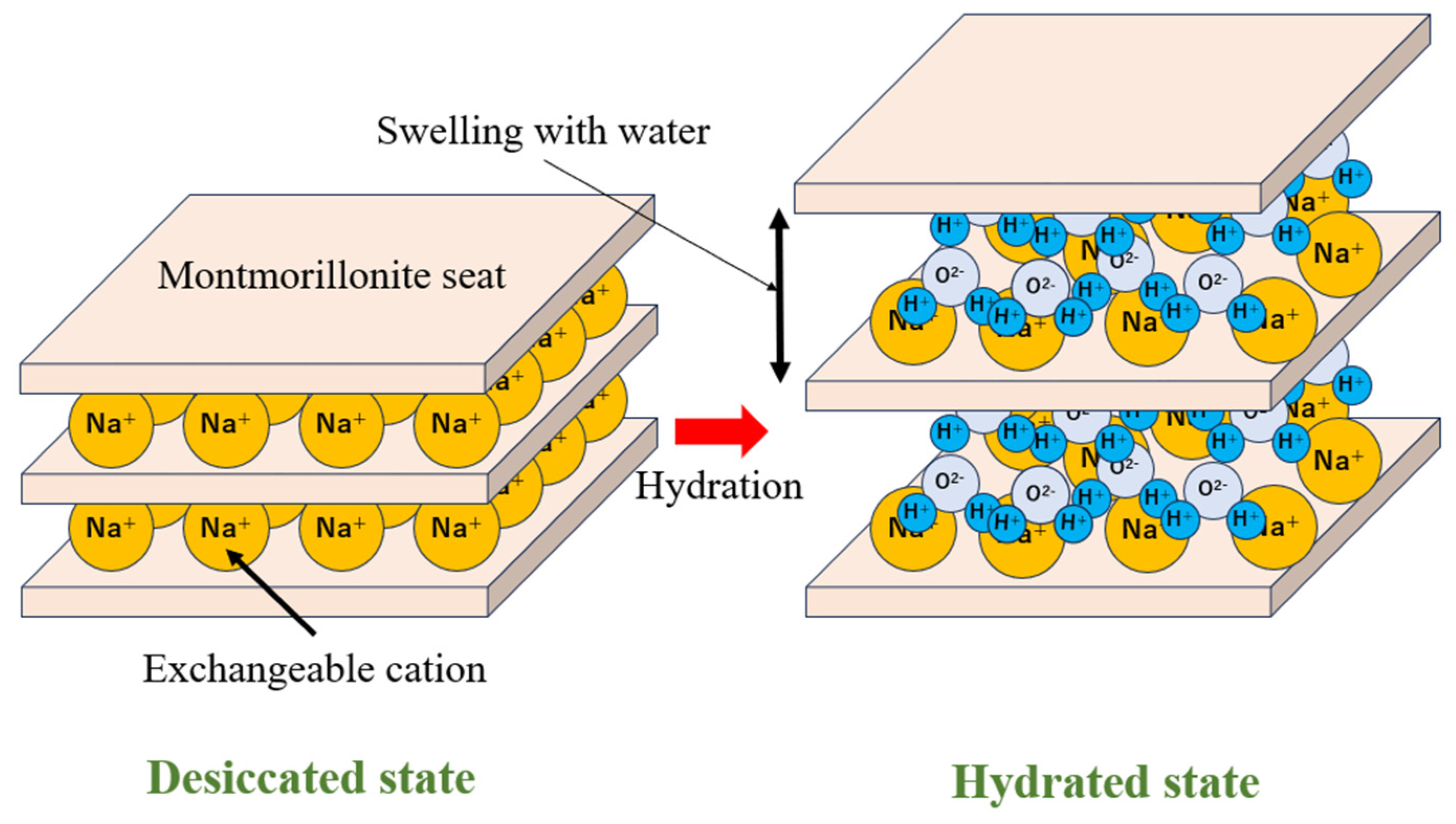
Swelling of bentonite occurs when montmorillonite meets water and water molecules selectively penetrate the interlayer using the hydration and solvation energy of the cations in the interlayer as the driving force, thereby pushing the interlayer apart. Figure 1 illustrates the concept of montmorillonite swelling due to interlayer hydration. According to the principle of swelling, the swelling property depends on the type of cation in the interlayer. When in contact with salty water, such as seawater, Na+ and Cl- ions in the brine also attract water molecules by hydrating them, so that some of the water trying to enter the interlayer is lost to them, thereby reducing the swelling property. When bentonite absorbs water, it swells 5.89~7.48 times its volume in compacted bentonite (KunigelV1) with a dry density of 1.2 Mg/m3 [6]. The ratio of the volume after swelling equilibrium to the original volume is called the volume swelling ratio, which depends on the montmorillonite content, cation species in the interlayer, and water quality. When the volume of bentonite is constrained to prevent swelling, swelling stress (swelling pressure) is generated as a reaction force. The mechanical buffering function is exhibited by self-regulating water absorption and dehydration in response to external pressure.
In previous studies, for example, data on swelling were obtained mainly for Na-bentonite such as KunigelV1, using parameters such as dry density, silica sand mixing ratio, and salt concentration [7], and have been published as the Buffer Material Database [8].
On the other hand, there is no thermodynamic data on the hydration of K-bentonite, which is the subject of this study. However, there are few studies on the interlayer distance and swelling stress of K-bentonite. From these reports, it can be inferred that the swelling power is likely to change in comparison with that of Na-bentonite. The Japan Atomic Energy Agency’s Project for Validating Assessment Methodology in Geological Disposal Systems [9] reported that the swelling power was lower for the K-type than for the Na-type. In addition, a study of the basal spacing (distance between layers and one sheet combined) of K-montmorillonite using an X-ray diffractometer reported that it is mostly 1-water molecular layers, even under 100% humidity conditions. Furthermore, studies by Morodome et al. [10] using X-ray diffraction measurements reported that the basal spacing of K-montmorillonite swelled up to that of the one-layer hydration state, and the two-layer hydration state was not observed. Saito et al. [11] also studied the adsorption and desorption processes of water into the interlayer of homo-ionic montmorillonite using an X-ray diffractometer and reported that K-montmorillonite has only one water molecular layer penetrating into the interlayer.
To summarize the above studies, although it is predicted that the swelling stress of K-montmorillonite is smaller than that of Na-montmorillonite due to its low hydration force and weak swelling property, no specific thermodynamic data on interlayer water are available.
1.3. Purpose of Research
As mentioned above, none of the thermodynamic data for K-montmorillonite interlayer water is available, and the data have not yet been discussed in detail, including the uncertainties and reliability of the data. It is possible that alteration of Na-bentonite used as a buffer material may occur during long-term isolation of high-level waste due to groundwater intrusion, which gradually replaces cations in the interlayer with K+ ions, even if they are initially Na+ ions. In other words, this change in physical properties due to cation exchange may affect the buffer material.
In view of this situation, the objective of this study is to obtain thermodynamic data on K-montmorillonite interlayer water and to analyze the swelling stress using a thermodynamic model, considering the alteration of Na-bentonite.
2. Thermomechanical Analysis of Swelling Stress
2.1. Thermodynamic Model for Swelling Stress at a Constant Temperature
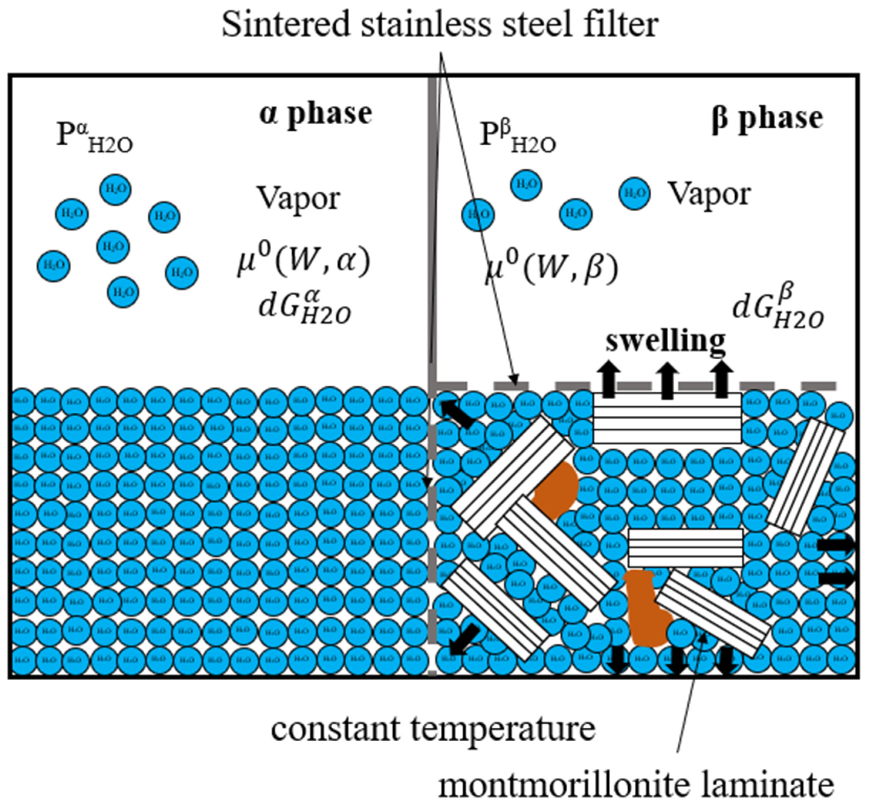
Figure 2 shows the concept of the thermodynamic model when pure water and bentonite are in contact through a sintered stainless-steel filter. Consider a system in which pure water is the α phase and the bentonite phase is the β phase, and the two are in contact only through a sintered stainless-steel filter (which is not deformed). The upper part of the water phase and the upper part of the bentonite phase are completely independent, and the vapor pressures at the top of each reflect the respective water conditions. The upper bentonite phase is also in contact with the upper air phase through a filter, and the bentonite is kept constant in volume. In this case, no volume change occurs in appearance when water is absorbed.
Since the chemical potential of water in both phases is equal when water infiltrates from phase α to phase β and the two phases are in equilibrium, the following relationship is established:
where,
: Chemical potential of waters in the α phase in standard state
: Chemical potential of waters in the β phase in standard state
The following parameter is defined as an indicator of water activity:
where,
: Water activity
P: Vapor pressure of the waters at any temperature
Find the chemical potential of each water in both phases. The free energy of water in the α and β phases when water infiltrates from the α phase to the β phase and the two phases are in equilibrium in the standard state (temperature 25 °C = 298.15 K) can be determined from the following relationship by knowing the vapor pressure at the top of each phase, respectively.
where,
: Relative partial molar Gibbs free energy of water in the α phase
: Relative partial molar Gibbs free energy of water in the β phase
R: gas constant (8.314462618 J/mol/K)
T: absolute temperature (In the standard state, T0 =298.15 K)
: Water vapor pressure of the waters in the α phase at any temperature
: Water vapor pressure of the waters in the β phase at any temperature
Regarding the activity of pure water (free water) in the standard state, the vapor pressure at the same temperature is the saturated vapor pressure of pure water, so the activity of pure water is 1 from Equation (4). In this case, the free energy of water in the α phase is from Equation (2). On the other hand, in the β phase, the free energy of water changes as water infiltrates and does work from the outside. Originally, if there is no filter at the top of the bentonite, the bentonite should swell and increase in volume to do work externally, but in this case, the volume is held constant, which means that pressure (stress) is applied to the filter. This is the swelling stress (or swelling pressure), which acts as swelling energy for the entire β phase. Since both phases are in equilibrium in this state, the chemical potential of water between the two phases is equal, and the following relationship holds.
where,
: Swelling stress at dried condition (0 in a dry state)
: Swelling stress at saturated condition
: Molar volume of water (18.0686 cm3/mol, 25 °C)
From Equation (8), if the swelling stress of bentonite when dry is set to 0 and the volume of water is constant (incompressible fluid), the swelling stress in a pure water system in its standard state can be calculated from the following equation:
where,
: Swelling stress
The correlation between relative humidity and water activity is expressed by the following equation:
where,
RH: Relative humidity
From Equation (10), Equation (4) can be expressed as the correlation between relative humidity and the free energy of the relative partial molar Gibbs as follows:
Furthermore, from Equation (10), by expressing Equation (9) for swelling stress using Equation (11), the correlation between swelling stress and relative humidity can be expressed as follows:
2.2. Analysis Conditions
In the measurement, KunipiaF (Na-montmorillonite, manufactured by KUNIMINE INDUSTRIES, montmorillonite content = 99% or more) was used as the starting material, and the sample was treated by replacing all cations in the montmorillonite interlayer with K+ ions (the experimental procedure is described below). KunipiaF is the bentonite with extremely high montmorillonite content that has been purified with water after crushing the raw bentonite ore to remove most impurities, and therefore, in this study, the montmorillonite content was treated as 100%. In addition, water vapor pressure is conventionally measured by the vapor pressure method [14,15,16], in which water vapor pressure is directly measured, but since the equipment is extremely rigid in this case, this study was conducted using the relative humidity method, a new measurement method based on the correlation between vapor pressure and relative humidity (experimental procedures are described later) [4].
The temperature (room temperature: temperature-controlled room) and the relative humidity were measured for K-montmorillonite using the relative humidity method with water content as a parameter. The thermodynamic data of water activity and relative partial molar Gibbs free energy were determined, and the swelling stress was analyzed based on these data and the thermodynamic model and compared with the existing measured data.
For comparison with the measured data, data obtained for various types of bentonites and bentonite dry density were plotted against montmorillonite partial density, focusing on montmorillonite content in bentonite, and compared. The montmorillonite partial density for any given bentonite can be obtained from the following equation [17]:
where,
: Montmorillonite partial density
: Bentonite dry density
: Average solid density of impurities excepting montmorillonite (=2.7 )
: Solid density of silica sand (=2.7 )
: Silica sand content
: Montmorillonite content in the bentonite
Although Equation (13) is calculated for bentonite dry density, experiments using the relative humidity method were performed with the water content of montmorillonite as a parameter. The conversion from the water content of montmorillonite to the montmorillonite partial density with the pore saturated can be obtained by the following equation [18]:
where,
: Solid density of montmorillonite (=2.7 )
: Water content (%)
: Density of water in standard state (=0.997044 )
In this study, temperature (room temperature) and relative humidity were measured using the relative humidity method; however, temperature differs slightly from the standard state. Therefore, the density of water used in Equation (14) was converted [19] accordingly to match the actual temperature measured. Since the molar volume value used in Equation (12) also changed, the molar volume at each temperature was obtained from the ratio of the density of water to the molar volume.
Thermodynamic data were measured for various water content, but there are no directly comparable K-bentonite data available for comparison with actual measurements. Therefore, comparisons were made against Na-bentonite KunipiaP, KunigelV1, KunipiaF, MX-80, KunipiaF (silica sand mixed system) [8,14,15,16,20] and Ca-KunigelV1 [21].
2.3. Substitutional Synthesis of K-Montmorillonite
In the substitutional synthesis of K-montmorillonite, Kunipia F (made by Kunimine Industries Co., Ltd., Tokyo, Japan). with a montmorillonite content of more than 99%), a Na-bentonite, was used. The substitution process for exchangeable cations in the montmorillonite interlayer was performed according to the procedure of Sato et al. [17]. Figure 3 shows a flowchart of the substitution synthesis of K-montmorillonite. The starting material, Kunipia F, was dried in a thermostatic bath (Yamato Scientific Co., Ltd., Tokyo, Japan) at 105 °C for several days and then weighed at 10.00 g on an electronic balance (AND Co., Ltd., Tokyo, Japan). The weighed bentonite and 400 mL of 1 M aqueous solution of potassium chloride were placed in a triangular flask (500 mL) with a rotor at a liquid volume ratio of 40 mL/g and stirred with a hot stirrer (Nissin Rika Co., Ltd., Tokyo, Japan). A special-grade reagent (purity > 99.5%) manufactured by Hayashi Pure Chemical Industry Ltd. (Shiga, Japan) was used to prepare the aqueous solution of potassium chloride.
The stirred suspension was allowed to stand still for approximately 24 h, after which the bentonite was allowed to soak and solid-liquid separation was performed. When the suspension was allowed to stand, the bentonite was agglomerated and separated into two layers: a solid-phase portion and a liquid-phase portion. This is because when the salt concentration is high, such as in a 1 M aqueous solution of potassium chloride, the bentonite agglomerates and settles at the bottom of the vessel due to the thinning of the electric double layer on the montmorillonite surface, and the effect of the interlayer ions becoming less hydrated (osmotic pressure decreases toward the outer layer). Solid-liquid separation was performed using this effect by discarding the supernatant of the suspension, which was separated into two layers, and then collecting the supernatant near the boundary phase with a pipette. Next, 400 mL of the newly prepared 1 M aqueous solution of potassium chloride was added and allowed to soak for about 24 h, followed by solid-liquid separation using the same procedure. This procedure was repeated three times.
After the third immersion, the supernatant solution was discarded as much as possible, and the suspension was transferred equally to four centrifuge tubes for solid-liquid separation by centrifugation. The final weight balancing was done while pipetting distilled water. The centrifugation time was determined from Stokes’ law by the following equation [22]:
where,
t: Time (min)
: Viscosity of water (, 20 °C)
: Specific gravity of the suspended particle
: Specific gravity of water
D: Diameter of the suspended particle to be collected (cm)
R: Length from the center of the rotor to the sediment surface (cm)
S: Length from the center of the rotor to the suspended solution surface (cm)
N: Revolutions per minute (rpm)
In this study, the specifications of the centrifuge (manufactured by AS ONE Corporation) and centrifuge tube were examined, and t = 7.36 min was obtained for the following conditions: R = 14 cm, S = 5 cm, = 2.7, = 1.0, D = 0.5 mm ( cm), N = 3000 rpm Centrifugation was performed at 3000 rpm for 8 min. The supernatant solution was discarded and washed with 80% ethyl alcohol (using a 99.5% pure reagent from Junsei Chemical Co., Ltd., Tokyo, Japan). This operation was repeated three times.
For the removal method of residual chloride ions (), the suspension after washing was filled into a cellulose dialysis tubing (manufactured by KENIS LIMITED, Osaka, Japan), tied at both ends, and brought into contact with a large volume of distilled water. The pH and electrical conductivity of the distilled water were measured approximately every 24 h using a personal pH/ORP meter (Yokogawa Electric Corporation, Musashino-shi, Japan) and a personal SC meter (Yokogawa Electric Corporation).
To confirm that the Cl− ions had been removed, the distilled water that had been in contact was aliquoted into a test tube while the distilled water was changed every few days, and about several drops of 0.1 M AgNo3 (Hayashi Pure Chemical Industries, Ltd., Shiga, Japan) were added until AgCl was no longer cloudy.
After the AgCl was no longer cloudy, the suspension in the cellulose dialysis tubing was transferred to a container with a flat bottom and dehydrated at room temperature. The sample (plate-like) obtained by natural dehydration was then crushed in a mortar and dried in a constant-temperature chamber at 105 °C. The final weight of K-montmorillonite obtained was 6.13 g, and the recovery was 61.3% (10 g input).
2.4. Vapor Pressure Measurement by Relative Humidity Method
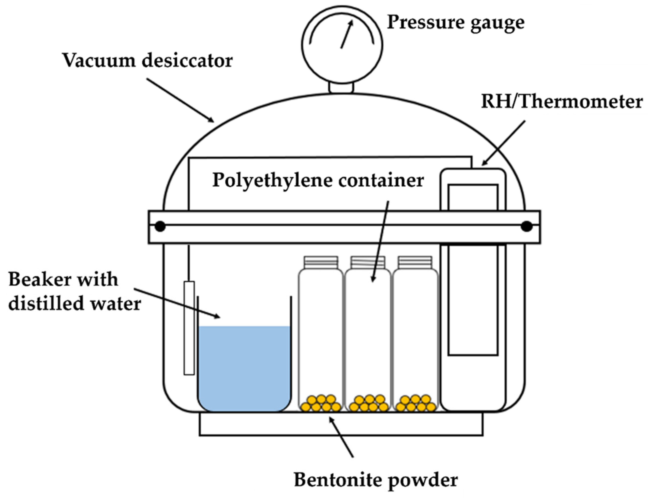
The vapor pressure of K-montmorillonite synthesized by the substitution method (Section 2.3) was measured by the relative humidity (RH) method. Figure 4 shows a conceptual diagram of vapor pressure measurement by the relative humidity (RH) method. 2.00 g of K-montmorillonite powder was dried in a constant temperature chamber at 105 °C, weighed with an electronic balance, and transferred to three polyethylene containers. To initially adsorb water vapor into the sample, a polyethylene container, a beaker containing distilled water, and a relative humidity/thermometer (AND Co., Ltd., Tokyo, Japan) were transferred to a vacuum desiccator (SANPLATEC Co., Ltd., Osaka, Japan), evacuated using a vacuum pump aspirator (Mitsubishi Fuso Truck and Bus Corp., Kawasaki, Japan), and held under 100% relative humidity conditions. The vacuum was maintained at 100% relative humidity. Approximately every 24 h, the water-containing weight was measured, and the sample was allowed to hydrate until there was no change in weight, in other words, until it was saturated. After saturation, the beaker containing distilled water was removed from the vacuum desiccator, vacuumed for a while to lower the water content, sealed in an almost vacuum condition, and after about 24 h, the relative humidity and temperature were measured, the sample was removed, and the water content weight was measured. The sample was then returned to the vacuum desiccator, vacuumed for a while to lower the water content, and the same operation was performed. Thus, the relative humidity and temperature were measured in the vacuum desiccator with the water content as a parameter.
3. Measurement Results and Discussion
3.1. Measurement Results
Figure 5 shows the water absorption curve of K-montmorillonite during the hydration process. The water content of K-montmorillonite reached a plateau state (saturated state) at 24.5–30%. This corresponds to one layer of hydration from the montmorillonite surface (22.4% water content (one layer of hydration) and 44.8% water content (two layers of hydration (two layers of hydration from the montmorillonite surface)), which is also consistent with results from previous studies [9,10,11].
Next, from the temperature and relative humidity measured in the relative humidity method, the water activity and relative partial molar Gibbs free energy in the β phase (bentonite phase) were determined based on Equations (10) and (11) and compared with Kunipia P (Na-montmorillonite) [14,15,16], respectively, as shown in Figure 6 and Figure 7. Both the water activity and relative partial molar Gibbs free energy began to decrease from around 15% water content. This indicates that the water affected by the K-montmorillonite surface is in the region of about one water molecule layer. The relative partial molar Gibbs free energy (dGH2O) at this time was about −1 kJ/mol at a water content ratio of 10%, which was higher than that of Na-montmorillonite. This indicates that the swelling stress of K-montmorillonite is lower than that of Na-montmorillonite.
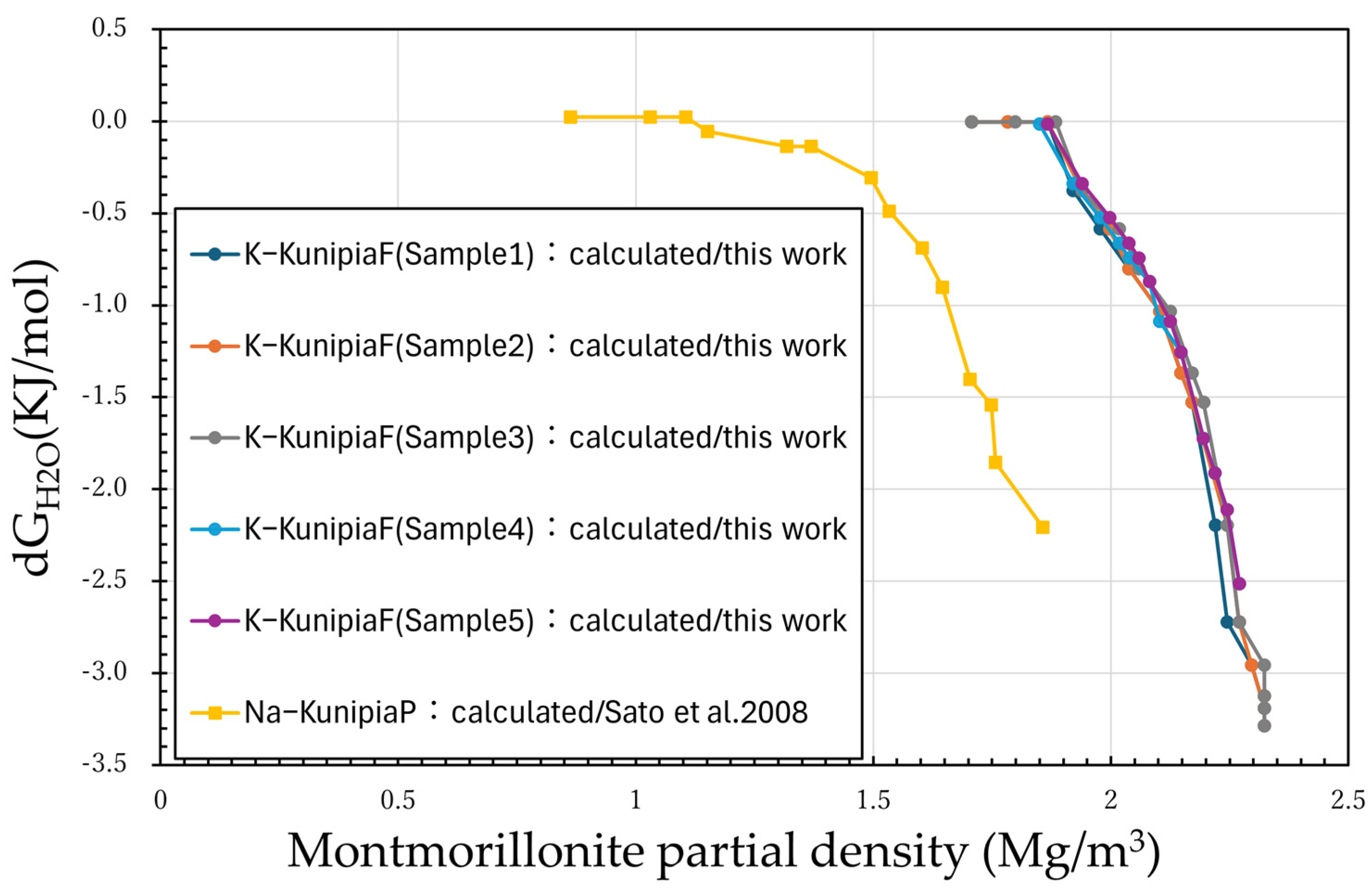
Next, the correlation between montmorillonite partial density and the relative partial molar Gibbs free energy (dGH2O) is shown in Figure 8. K-montmorillonite showed a decrease in the free energy of relative partial molar Gibbs with increasing montmorillonite partial density. It was also higher than that of Na-montmorillonite at the same density. This indicates that the swelling stress is lower than that of Na-montmorillonite.
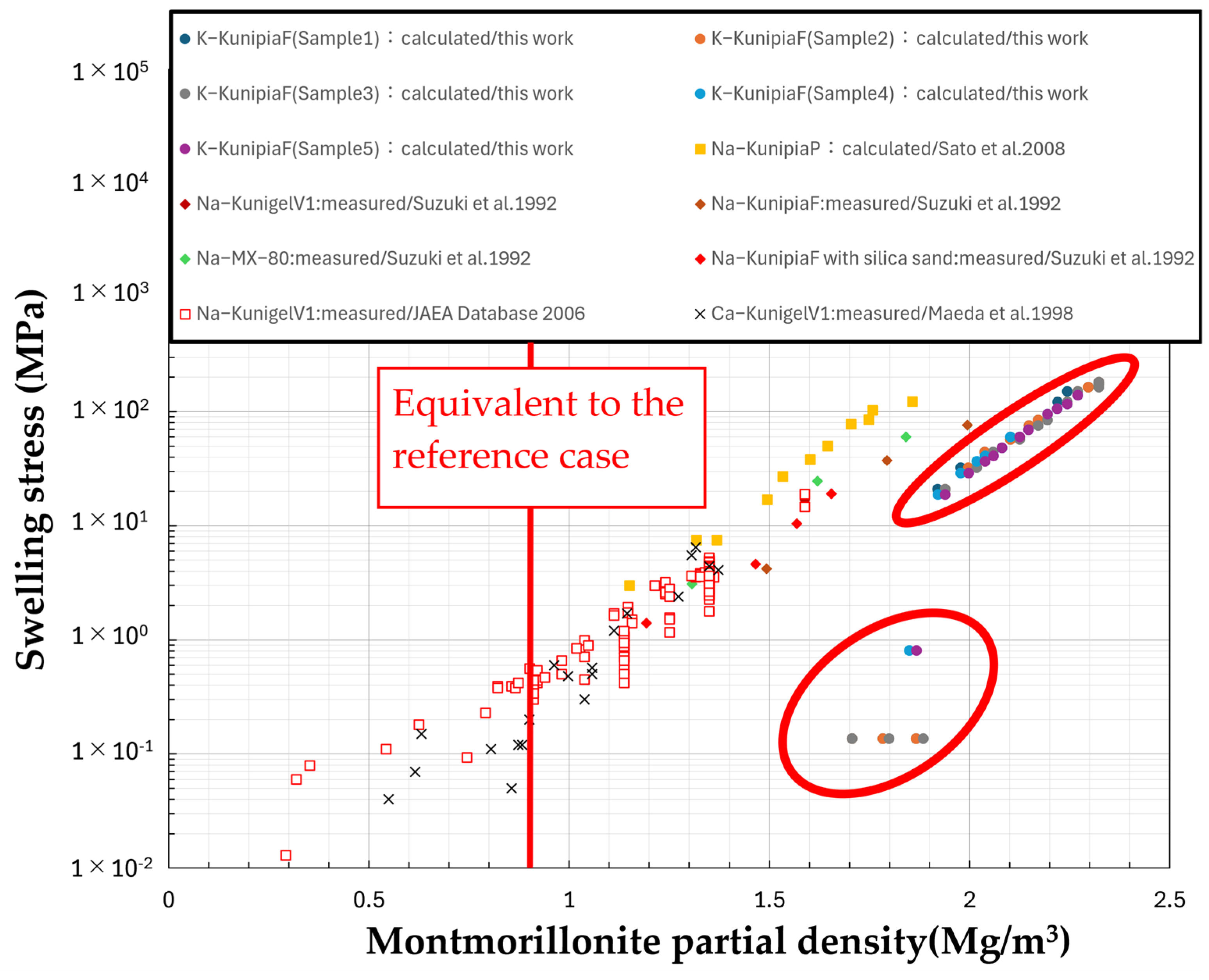
Finally, a comparison of the measured swelling stress against montmorillonite partial density under pure water conditions for various Na-bentonites, silica sand mixtures, and Ca-Kunigel V1 with different montmorillonite contents [8,14,15,16,20,22] and the thermodynamic model analysis results for K-montmorillonite is shown in Figure 9. It was found that K-montmorillonite swells only in the high-density region with a montmorillonite partial density of 1.9 Mg/m3 and barely swells in the density region below 1.8 Mg/m3.
3.2. Discussion
In K-Kunipia F, the activity of pure water and the relative partial molar Gibbs free energy decreased with decreasing water content, indicating that water is bound at or near the montmorillonite surface due to the reduced water content. This is similar to the trend observed for Kunipia P (100% Na-montmorillonite), a Na-bentonite that was compared. However, for Kunipia P, a Na-bentonite, the decrease in activity from around 1 with the reduction in water content is gradual, whereas, for Kunipia F, a K-bentonite (containing more than 99% K-montmorillonite), the decrease in activity was relatively sharp. The trend of the relative partial molar Gibbs free energy of Kunipia F, a K-bentonite, decreasing from around 0 was also similarly rapid. This implies that the degree of water binding on the surface of K-montmorillonite is stronger compared to that of Na-type.
In the correlation between montmorillonite partial density and the relative partial molar Gibbs free energy, for Kunipia P, a Na-bentonite, the relative partial molar Gibbs free energy decreases gradually with the increase in montmorillonite partial density, whereas for Kunipia F, a K-bentonite, it sharply decreases around the region of 1.8 to 1.9 Mg/m3 in montmorillonite partial density. This indicates that, similar to the correlation between the activity of pure water and the relative partial molar Gibbs free energy with water content, the degree of water binding on the surface of K-montmorillonite is stronger compared to that of Na-type.
In the correlation between montmorillonite partial density and swelling stress, Na- and Ca-bentonites exhibit similar levels of swelling stress at low montmorillonite partial densities, whereas K-type shows almost no swelling below a montmorillonite partial density of 1.8 Mg/m3, swelling only in the higher density region at 1.9 Mg/m3. This indicates that K-bentonite hardly swells under normal design conditions. In other words, it suggests that when Na-bentonite, used as a buffer material, undergoes alteration due to the infiltration of groundwater that replaces the interlayer cations with K+ ions, it becomes less prone to swelling.
4. Conclusions
4.1. Summary
In this study, we prepared samples in which all the cations in the interlayers of montmorillonite, the main component of bentonite, were replaced with K+ ions. We obtained thermodynamic data on the interlayer water using the relative humidity method, with the water content as a parameter, and analyzed the swelling stress using a thermodynamic model. Furthermore, we determined the correlation between montmorillonite partial density and swelling stress and compared it with existing actual measurement data.
The correlation between the activity of pure water and the free energy of relative partial molar Gibbs and water content indicates that K-montmorillonite has a stronger degree of water binding on the montmorillonite surface than Na-montmorillonite. The correlation between the montmorillonite partial density and the relative partial molar Gibbs free energy also indicates that the K-montmorillonite has a stronger degree of water binding on the K-montmorillonite surface than the Na-type.
The correlation between the montmorillonite partial density and the swelling stress showed that K-bentonite hardly swells in the low-density region at the montmorillonite partial density compared to interlayer cations such as Na- and Ca-bentonite. This indicates for the first time that K-bentonite is likely to have little swelling under the design conditions of buffer materials in a normal repository. This suggests that Na-bentonite used as a buffer material is less likely to swell when groundwater intrusion causes alteration of the interlayer by the replacement of cations with K+ ions. Since the thermodynamic data obtained are extremely scarce, the reliability of the data is a future issue.
4.2. Future Issues
In this study, thermodynamic data of interlayer water were obtained by the relative humidity method with water content as a parameter, and the swelling stress was analyzed by a thermodynamic model, suggesting that K-montmorillonite is less susceptible to swelling at montmorillonite partial densities in the normal design than interlayer cations of Na- and Ca-montmorillonite. However, the thermodynamic data obtained are scarce, and it is not possible to discuss even the uncertainty and reliability of the data.
We plan to obtain more thermodynamic data to study in detail.
Author Contributions
Conceptualization, H.S.; methodology, H.S.; validation, M.E.; formal analysis, M.E.; investigation, M.E.; resources, H.S.; data curation, M.E.; writing—original draft preparation, M.E.; writing—review and editing, M.E.; visualization, M.E.; supervision, H.S.; project administration, H.S.; funding acquisition, H.S. All authors have read and agreed to the published version of the manuscript.
Funding
This study was conducted by the Grant-in-Aid for Scientific Research of the Japan Society for the Promotion of Science (JSPS) (No. 20K05383).
Data Availability Statement
Dataset available on request from the authors; The raw data supporting the conclusions of this article will be made available by the authors on request.
Conflicts of Interest
The authors declare no conflict of interest.
References
- Japan Nuclear Cycle Development Institute. Technical Reliability on Geological Disposal of HLW in Japan—Second Progress Report on Research and Development for the Geological Disposal of HLW in Japan—General Report, JNC TN1400 99-020. 1999. Available online: https://jopss.jaea.go.jp/pdfdata/JNC-TN1400-99-020.pdf (accessed on 15 February 2024). (In Japanese).
- Sato, H. Function for Controlling Nuclide Migration of Buffer Material in the Geological Disposal for High-Level Radioactive Waste. J. MMIJ 2009, 125, 1–12. Available online: https://www.jstage.jst.go.jp/article/journalofmmij/125/1/125_1_1/_pdf/-char/ja (accessed on 15 February 2024). (In Japanese). [CrossRef]
- Sato, H. Quantification of Exchangeable Cations in Interlayer of Tsukinuno Sodium-Montmorillonite. Mater. Res. Soc. Symp. Proc. 2009, 1193, 529. [Google Scholar] [CrossRef]
- Sato, H. Measurements of Thermodynamic Data of Water in Na-Bentonite in the Pressure Release System and Standard Condition by Relative Humidity Method, Atomic Energy Society of Japan [2022 Fall Meeting], 3C12. 2022. Available online: https://confit.atlas.jp/guide/event-img/aesj2022f/3C12/public/pdf?type=in (accessed on 15 February 2024). (In Japanese).
- Ito, M.; Okamoto, M.; Shibata, M.; Sasaki, Y.; Danbara, T.; Suzuki, K.; Watanabe, T. Mineral Composition of Bentonite, PNC TN8430 93-003; Japan Nuclear Cycle Development Institute (JNC): Ibaraki, Japan, 1993. (In Japanese) [Google Scholar]
- Kikuchi, H.; Tanai, K. Basic Characteristic Test of Buffer/Backfill Material under Horonobe Groundwater Condition (Testing Document), JNC TN8430 2004-005; Japan Nuclear Cycle Development Institute (JNC): Ibaraki, Japan, 2005. (In Japanese) [Google Scholar]
- Suzuki, H.; Fujita, T. Swelling Characteristics of Buffer Material, JNC TN8400 99-038; Japan Nuclear Cycle Development Institute (JNC): Ibaraki, Japan, 1999. (In Japanese) [Google Scholar]
- Japan Atomic Energy Agency (JAEA). Database on Basic Characteristics of Buffer Material. Available online: https://bufferdb.jaea.go.jp/bmdb/ (accessed on 20 January 2023).
- Agency for Natural Resources and Energy, Ministry of Economy, Trade and Industry. The Project for Validating Assessment Methodology in Geological Disposal System. 2013. Available online: https://www.enecho.meti.go.jp/category/electricity_and_gas/nuclear/rw/library/2013/25-7-1.pdf (accessed on 15 February 2024). (In Japanese).
- Morodome, S.; Kawamura, K. In Situ X-ray Diffraction Study of the Swelling of Montmorillonite as Affected by Exchangeable Cations and Temperature. Clays Clay Miner. 2011, 59, 165–175. Available online: https://link.springer.com/article/10.1346/CCMN.2011.0590205 (accessed on 15 February 2024). [CrossRef]
- Saito, Y.; Okawara, M. Study on State of Water in Homo-Ionic Montmorillonite by X-Ray Diffraction and Near-Infrared Spectroscopy. Clay Sci. 2019, 58, 43–59. Available online: https://www.jstage.jst.go.jp/article/jcssjnendokagaku/58/2/58_580203/_pdf/-char/ja (accessed on 15 February 2024). (In Japanese).
- The Japan Society of Mechanical Engineers. 1980 JSME Steam Tables in SI; JSME: Tokyo, Japan, 1981. (In Japanese) [Google Scholar]
- Nihon, K.; Kagaku, B.; Kisohen, K. Edition Handbook of Chemistry, Basic Version, Revised 6th Edition; Maruzen Publishing Co., Ltd.: Tokyo, Japan, 2021. (In Japanese) [Google Scholar]
- Sato, H. A Thermodynamic Approach on Effect of Salinity on Swelling Pressure of Bentonite. In Proceedings of the 4th Japan-Korea Joint Workshop on Radioactive Waste Disposal 2008: Perspective of Science and Engineering, Hakone, Japan, 27–28 May 2008; pp. 1–17. [Google Scholar]
- Sato, H. Thermodynamic Understanding on Swelling Pressure of Bentonite Buffer. In Proceedings of the 15th International Conference on Nuclear Engineering (ICONE15), Nagoya, Japan, 22–26 April 2007. ICONE15-10207; Available online: https://www.jstage.jst.go.jp/article/jsmeicone/2007.15/0/2007.15__ICONE1510_99/_pdf (accessed on 15 February 2024).
- Sato, H. Thermodynamic Model on Swelling of Bentonite Buffer and Backfill Materials. Phys. Chem. Earth 2008, 33, S538–S543. [Google Scholar] [CrossRef]
- Sato, H. Purification of Na-smectite and preparation of oriented samples for diffusion experiments, JAEA-Research 2005-004. 2006. Available online: https://jopss.jaea.go.jp/pdfdata/JAEA-Research-2005-004.pdf (accessed on 15 February 2024). (In Japanese).
- Sato, H. Swelling and Thermodynamic of Buffer Material as the Engineered Barrier in the Geological Disposal. Nucl. Backend Res. 2020, 27, 105–114. Available online: https://nuce.aesj.or.jp/jnuce/vol27/Jnuce-Vol27-2-p105-114.pdf (accessed on 15 February 2024). (In Japanese).
- National Institutes of Natural Sciences, National Astronomical Observatory of Japan. Chronological Scientific Tables, Desktop version; Maruzen Publishing Company Ltd.: Tokyo, Japan, 2012; p. 383. (In Japanese) [Google Scholar]
- Suzuki, H.; Shibata, M.; Yamagata, J.; Hirose, I.; Terakado, K. Characteristic Test of Buffer Material (1), PNC TN8410 92-057. 1992, pp. 1–103. Available online: https://jopss.jaea.go.jp/pdfdata/PNC-TN8410-92-057.pdf (accessed on 15 February 2024). (In Japanese).
- Maeda, M.; Tanai, K.; Ito, M.; Mihara, M.; Tanaka, M. Mechanical properties of the Ca exchanged and Ca bentonite—Swelling pressure, hydraulic conductivity, compressive strength and elastic modulus-, Power Reactor and Nuclear Fuel Development Corporation, PNC TN8410 98-021. 1998, pp. 1–136. Available online: https://jopss.jaea.go.jp/pdfdata/PNC-TN8410-98-021.pdf (accessed on 15 February 2024). (In Japanese).
- Shirozu, H. Clay Mineralogy—The Basis of Clay Science; Asakura Publishing: Tokyo, Japan, 2010. (In Japanese) [Google Scholar]
Figure 1.
Swelling of montmorillonite by hydration of interlayer.

Figure 2.
A conceptual model of the chemical potential balance of water in the equilibrium state between pure water (α phase) and water-saturated bentonite (β phase) through a sintered stainless-steel filter at a constant temperature.
Figure 2.
A conceptual model of the chemical potential balance of water in the equilibrium state between pure water (α phase) and water-saturated bentonite (β phase) through a sintered stainless-steel filter at a constant temperature.

Figure 3.
Preparation procedure of K-montmorillonite.
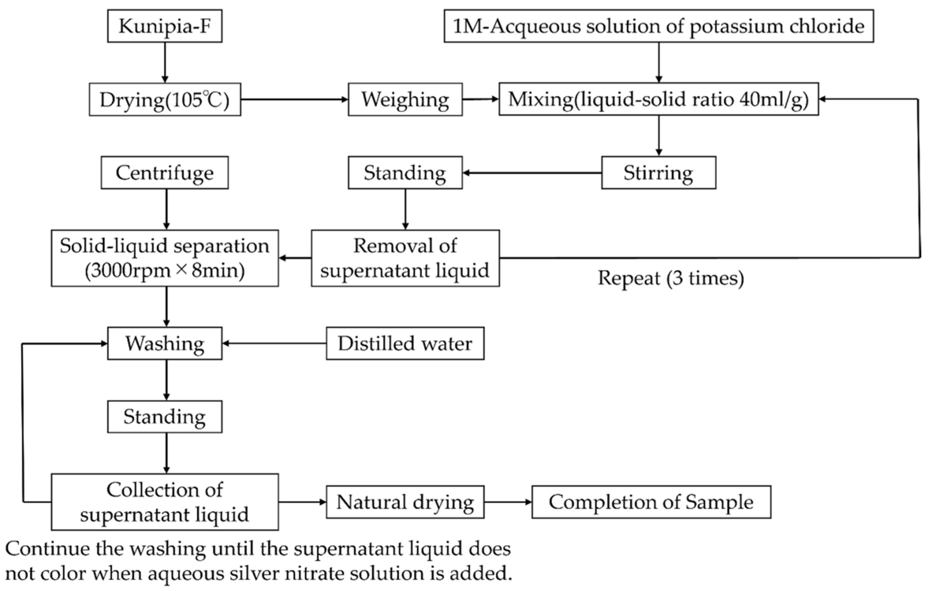
Figure 4.
Vapor pressure measurement by relative humidity method.

Figure 5.
Water absorption curve of K-montmorillonite.
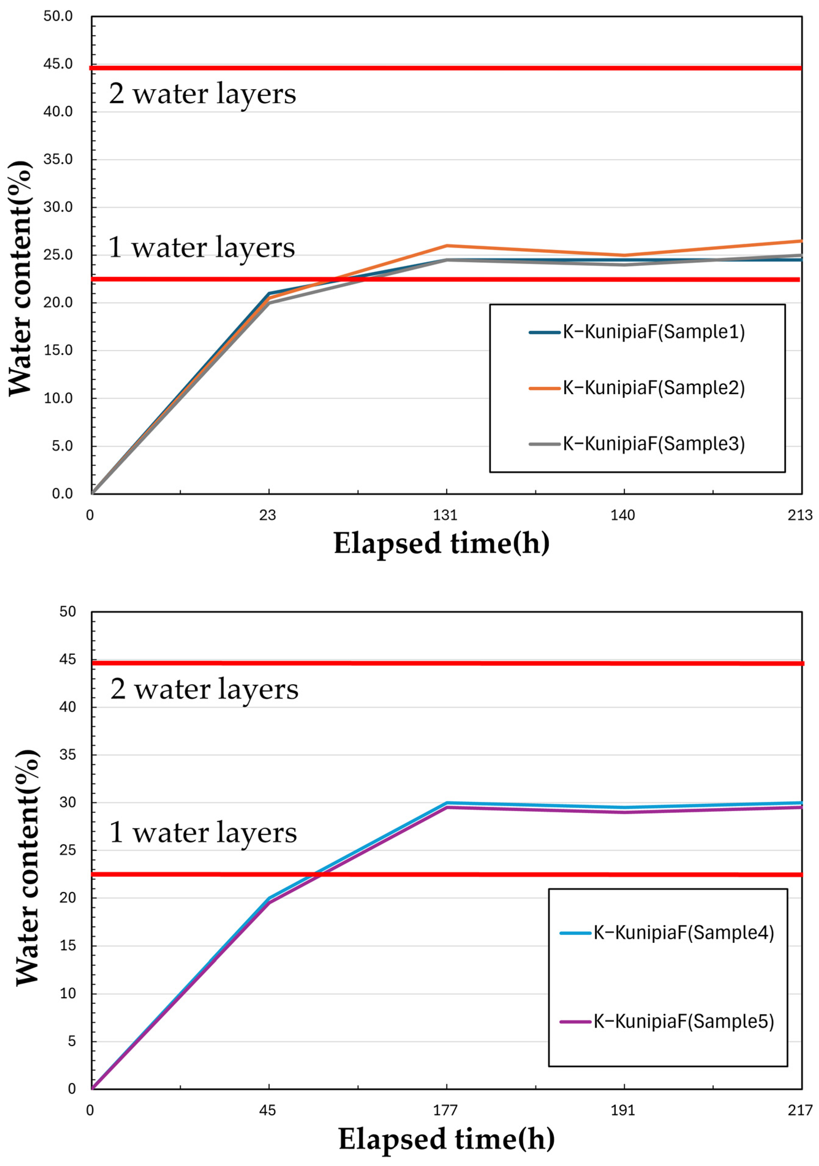
Figure 6.
Correlation between water content and activity of water [16].
Figure 6.
Correlation between water content and activity of water [16].
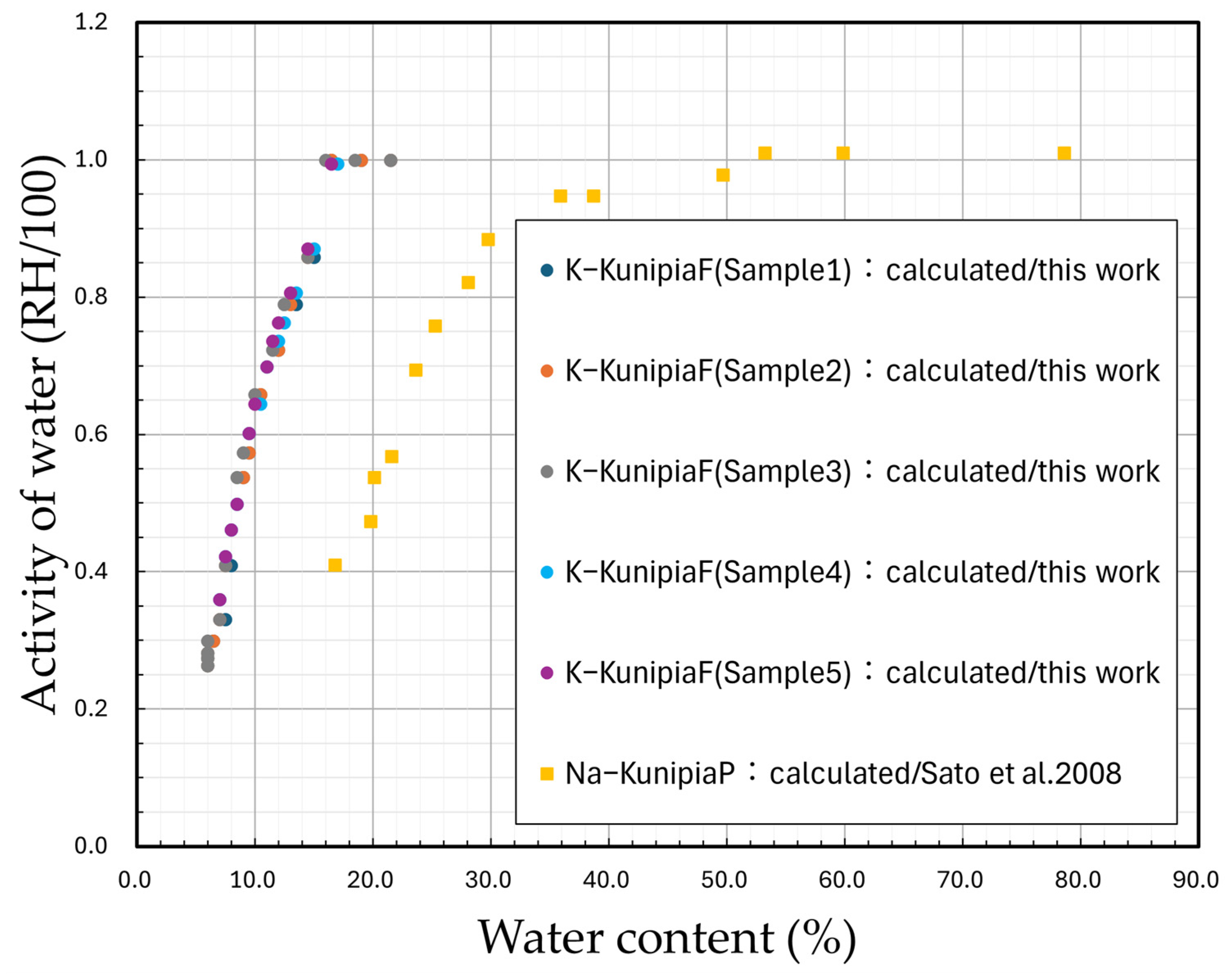
Figure 7.
Correlation between water content and relative partial molar Gibbs free energy [16].
Figure 7.
Correlation between water content and relative partial molar Gibbs free energy [16].

Figure 8.
Correlation between the montmorillonite partial density and relative partial molar Gibbs free energy [16].
Figure 8.
Correlation between the montmorillonite partial density and relative partial molar Gibbs free energy [16].

Disclaimer/Publisher’s Note: The statements, opinions and data contained in all publications are solely those of the individual author(s) and contributor(s) and not of MDPI and/or the editor(s). MDPI and/or the editor(s) disclaim responsibility for any injury to people or property resulting from any ideas, methods, instructions or products referred to in the content. |
© 2024 by the authors. Licensee MDPI, Basel, Switzerland. This article is an open access article distributed under the terms and conditions of the Creative Commons Attribution (CC BY) license (https://creativecommons.org/licenses/by/4.0/).
Share and Cite
MDPI and ACS Style
Endo, M.; Sato, H. Swelling Stress of Bentonite: Thermodynamics of Interlayer Water in K-Montmorillonite in Consideration of Alteration. Minerals 2024, 14, 430. https://doi.org/10.3390/min14040430
AMA Style
Endo M, Sato H. Swelling Stress of Bentonite: Thermodynamics of Interlayer Water in K-Montmorillonite in Consideration of Alteration. Minerals. 2024; 14(4):430. https://doi.org/10.3390/min14040430
Chicago/Turabian StyleEndo, Misato, and Haruo Sato. 2024. "Swelling Stress of Bentonite: Thermodynamics of Interlayer Water in K-Montmorillonite in Consideration of Alteration" Minerals 14, no. 4: 430. https://doi.org/10.3390/min14040430
Note that from the first issue of 2016, this journal uses article numbers instead of page numbers. See further details here.