
Oxide Reduction Treatment with a Thermal Plasma Torch: A Case Study

Département de Génie Chimique et de Génie Biotechnologique, Université de Sherbrooke, Sherbrooke, QC J1K 2R1, Canada
*
Author to whom correspondence should be addressed.
Minerals 2024, 14(5), 443; https://doi.org/10.3390/min14050443
Submission received: 25 March 2024
/
Revised: 20 April 2024
/
Accepted: 22 April 2024
/
Published: 24 April 2024
(This article belongs to the Special Issue Green Mining, Waste Recovery and Efficient Disposal of Metal Mines)
Abstract
:This article presents the findings of a study on oxide reduction utilizing a novel reducing plasma torch, employing greenhouse gases such as CO2 and CH4 as plasma gases. The primary aim of this investigation is to establish the viability of this approach. The innovative plasma torch was employed to reduce various oxides, including aluminum oxide, iron oxide, and titanium oxide, as well as a mixed oxide composition, employing a CO2/CH4 molar ratio of 1:1 within a spouted bed reactor. Following plasma treatment, X-ray diffraction (XRD) analysis was conducted to examine the metallic phases, notably titanium, iron, and aluminum. SEM–EDS observations were carried out to assess microstructural changes and identify elemental compositions pre- and post-plasma treatment. The results demonstrate that within the conical section of the reactor, titanium oxide experiences partial reduction, resulting in limited titanium production, while aluminum oxide and iron oxides (magnetite and hematite) undergo reduction to yield aluminum and iron, respectively. Thermodynamic calculations, performed using Factsage software version 8.3, were utilized to predict stable-phase formations following plasma treatment for each material.
1. Introduction
Metals in nature are generally found in oxidized form, except gold, which is often found in its native metallic form. When referring to ore, it generally means a complex mixture containing various metal oxides, sometimes combined with other components. This chemical diversity makes the process of extracting metals, known as extractive metallurgy, a complex and meticulous undertaking [1]. The main aim of extractive metallurgy is to reduce these metal oxides to recover pure metals. This process generally involves several stages, each designed to separate the metals from the other elements present in the ore and return them to their metallic form. Oxides can be reduced by various means, such as chemical reactions with reducing agents or by heating at high temperatures in a controlled environment [1].
Worldwide crude steel production currently stands at 1500 million tons per year, followed by other base metals and alloys. Most of these metals, including iron, aluminum, silicon, manganese, chromium, nickel, titanium, vanadium, and many others, are extracted from oxidized minerals. This extraction process typically utilizes carbon as a reducing agent, posing challenges in terms of future supply and environmental pollution. For instance, steel production alone contributes to 5% of total CO2 emissions [2].
Thermal plasma represents a versatile decarbonization solution for the large-scale manufacture of various advanced materials required in highly specialized industrial sectors. The growing demand for materials with improved physical and mechanical properties to meet the stringent requirements of cutting-edge industries such as aerospace, chemicals, electronics, semiconductors, transport, and nuclear energy is steadily increasing [3].
Moreover, plasmas are recognized for their superior efficiency compared to conventional heating methods and could eventually supplant them: the torch used in these experiments boasts an efficiency of 75% [4]. In addition, the plasma used in this study offers further advantages by consuming polluting gases such as CO2 and CH4.
Industrial plasmas can operate at pressures ranging from near vacuum to several atmospheres. Several significant industrial applications occur at or near atmospheric pressure, sometimes even in the air. These applications utilize non-equilibrium plasmas (non-LTE) with electron temperatures many orders of magnitude higher than the temperatures of the heavy components of the plasma, as well as thermal plasmas approaching local thermal equilibrium (LTE) [5]. For instance, one study examined the effects of low-temperature, non-equilibrium plasma generated by a dielectric barrier discharge in ambient air at atmospheric pressure on the acid–base, adsorption, and flotation properties of natural iron sulfides such as pyrite and arsenopyrite [6]. In another study, the application of the plasma–chemical ore treatment method using nanosecond pulsed dielectric barrier discharge (DBD) plasma at low temperatures in the air under atmospheric pressure showed promising prospects for selective separation processes of semiconducting ores, particularly sulfides and oxides [7].
When the temperature of a plasma is high enough, a local thermodynamic equilibrium (LTE) is reached. For plasma species in motion, LTE is the thermodynamic state achieved when collisions prevail in regions with modest spatial variations (where the plasma does not absorb its own radiation). High-density arc discharges are the only means of creating the plasmas required for industrial-scale pyrometallurgical processes [8]. These heated plasma arcs are created between a cathode and an anode. There is a wide variety of electrodes, each with its own shape and composition. The most common types of electrodes are rods, buttons, tubes, and rings. Rod and button electrodes are often made from thoriated tungsten (2%–3% ThO2) or graphite. Currently, plasma tools are either transferred arc systems or non-transferred arc devices. The process calls for electricity, which may be provided by the device’s operating current and voltage [9].
There are now two primary areas where thermal plasma technology is being applied: materials processing and waste treatment. Many high-tech companies rely on the large-scale, high-purity manufacturing of novel materials, and thermal plasma synthesis provides a flexible and cost-effective approach for this purpose. High-tech sectors, including aircraft, chemicals, electronics, semiconductors, transportation, and nuclear power, are increasingly aware of the need for materials with enhanced physical and mechanical qualities for demanding applications [10]. Over the past decade, plasma waste treatment has emerged as a crucial technology in the face of growing waste disposal challenges. This method has gained importance, not least due to a growing awareness of the potential for waste recovery and the production of valuable co-products [11]. For example, thermal plasma represents an essential tool in the transformation of waste-derived fuels, providing the optimum conditions for efficient pyrolysis and gasification processes, thus contributing to more sustainable waste management and the production of renewable energy [12]. A recent study brilliantly illustrates the successful integration of hybrid thermal plasma technology with carbon capture, utilization, and storage (CCUS) for sewage sludge treatment. This innovative approach offers the ability to transform sewage sludge into syngas while capturing a proportion of the carbon in solid form and converting CO2 to CO within the syngas [13]. A study has been carried out into the gasification of various organic materials in a steam plasma generated in a special plasma torch equipped with a water-stabilized arc. This unique configuration produces a thermal plasma characterized by very high enthalpy and low mass flow thanks to an arc discharge in direct contact with water [14]. In conjunction with this, a new process has been proposed and investigated using an equilibrium thermochemical modeling study to assess the effectiveness of an innovative technology that merges thermal plasma and thermochemical looping. This innovative approach aims to use hydrogen in the iron reduction process, opening up new prospects for the steel industry [15]. Recently, thermal plasma has gained worldwide popularity for the treatment of complex waste streams due to its many intrinsic advantages. These include the ability to produce hydrogen-enriched synthesis gas (H2) [16].
In comparison to existing DC thermal plasma torches, the newly developed DC torch represents a significant breakthrough in technology. By utilizing molecular gases, it provides both high plasma enthalpy (50 MJ/kg at 7000 K) and high thermal conductivity (≈4 W/m·K at 7000 K) [17]. One disadvantage of using argon as a plasma gas is its low thermal conductivity. This reduces the heat transfer rate to the treated materials. To overcome this, a small percentage of hydrogen or helium is typically added. While this addition improves heat transfer, it also accelerates electrodes’ erosion. During arc burning, hydrocarbons completely dissociate into free carbon and hydrogen. Under appropriate conditions, carbon ions from the gas phase diffuse to the cathode surface, establishing a dynamic equilibrium between carbon sublimation and precipitation [18]. The electrode is preserved and has a longer service life due to the carbon coating. For combustion, this torch utilizes a gas similar to carbon dioxide, which can be obtained in near-pure form from certain chemical firms as waste gas [19].
Potential uses for CO2/CH4 plasma torches are mainly unexplored. However, it is critical to emphasize their prospective capacity to reduce greenhouse gas (GHG) emissions, such as CO2, as well as other harmful gases, such as NOx [20]. Furthermore, these plasma torches might increase the consumption of the most harmful gases found across several industrial sectors. In this study, the CO2/CH4 torch utilized up to 3.6 m3·h−1 of gas, which is much less than gas burners, which may burn over 2000 m3·h−1 of fossil fuels [21]. However, using oxygen-enriched air may significantly decrease consumption by up to 25% [22].
The main purpose of this study is to demonstrate the viability of the concept of reducing oxides using a plasma torch powered by greenhouse gases such as CO2 and CH4. What particularly sets this research apart is its innovative exploration of the use of this type of plasma torch to reduce specific oxides, an approach that has not been attempted yet. Alumina, hematite, magnetite, and titanium oxide are only a few of the oxides that were studied for their reducing potential in this report. Metallic phases have been produced by adopting this approach. The reducing power of the plasma torch was increased, and high temperatures were attained by using a CO2/CH4 molar ratio of 1:1. After plasma treatment, metal phases including titanium, iron, and aluminum were detected using XRD analysis. SEM–EDS observations were performed to analyze the microstructure and identify the elemental composition of materials before and after plasma treatment, proving the technology’s efficacy in the field of material processing.
2. Materials and Methods
2.1. Chemicals
Argon gas (99 wt.% purity) was used to cool down the experiment, while pure CO2 (99 wt.% purity) and CH4 (99 wt.% purity) were used as plasma gases to generate a stable plasma arc. The experiment employed a molar gas ratio CO2/CH4 of 1:1. Each experiment was fed with Al2O3 (98 wt.%), Fe2O3 (98 wt.%), Fe3O4 (98 wt.%), and TiO2 (98 wt.%).
2.2. How a Plasma Torch Works
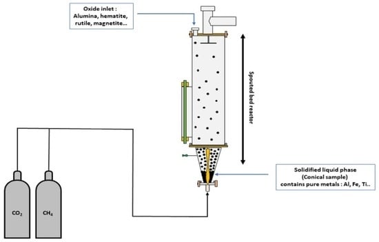
New-generation plasma torches can be easily connected to gas or electricity sources using a specially designed connector plate, reducing the amount of handling required. Within their metal casing, these torches contain three critical components (see Figure 1): a positively charged upstream electrode, a negatively charged downstream electrode, and a plasma gas injection chamber. When two electrodes come into contact, a short circuit is formed. An electric arc forms between the two electrodes when the upstream electrode is pushed back and the current increases. When plasma gas is introduced into the injection chamber, it creates a vortex around the arc [23]. A magnetic field generated by a specific coil causes the arc to rotate. This process helps to slow electrode wear, extending its useful life. When the introduced gas contacts the electric arc, it ionizes and transforms into plasma. Plasma, also known as the fourth state of matter after solids, liquids, and gases, is an ionized, electrically conductive medium. Its energy density is so high that temperatures in the heart of the arc can reach 5000 °C [24]. To protect the torch’s external environment from these extremely high temperatures, a water circulation system cools the metal casing, keeping the torch’s external temperature below 40 °C [25].
2.3. Experimental Procedure
A new direct current (DC) plasma torch (P60 with input power up to 60 kW) working with a gas combination of carbon dioxide (CO2) and hydrocarbon (methane (CH4)) has been employed for oxide reduction processing. Several steps were taken to prepare the equipment for the experiment. First, the torch was connected directly to the conical part of the reactor. Next, the feeding inlet was removed to allow access to the inside of the reactor. The material was dried at 105 °C overnight and then poured into the reactor through a tube to reach the conical section, while a flow of argon was injected to prevent contamination by unwanted particles inside the torch. Experiments were carried out using a feedstock consisting of particles of various sizes, ranging from 50 µm to 100 µm. In a spouting bed reactor, metal oxides such as aluminum oxide, titanium oxide, and iron oxide were reduced. The plasma torch was operated using a CO2/CH4 mixture with a molar ratio of 1:1, and the power applied was 38 kW. At the start of each experiment, a plasma jet was generated at the torch outlet, coming into direct contact with the material to be treated. The temperatures reached were extremely high, ranging from 4000 °C to 5000 °C, melting the material and forming a liquid phase. This liquid phase was then cooled using a flow of argon, giving rise to a molten material known as the "solidified liquid phase", which took on the same shape as the conical part of the reactor. The plasma reactor used for the experiments is shown in Figure 1 (spouted-bed reactor). The CO2/CH4 combination at high temperatures has a complex composition where the presence of CO might arise and decrease oxidation. The molar gas ratio of CO2 to CH4 was adjusted to 1 to produce a low-oxygen atmosphere. A stable plasma jet was achieved by maintaining the current at 252 A, and the voltage was set at 150 V. Although the pressure changed slightly, it remained close to 1 atm. The duration of each experiment was restricted to two minutes because of overheating of the conical part in direct contact with the torch and the emergence of hot spots throughout the trials.
2.4. Characterization Techniques
2.4.1. XRD Analysis
All phases were determined before and after plasma treatment using a Panalytical’s X’Pert Pro MPD diffractometer. CuKα radiation was used to measure angles ranging from 10° to 70° (angle 2θ) at a rate of 1° per minute. The angle may be adjusted as needed. The collected data were submitted to Rietveld analysis using HighScore Plus version 4.9 to determine the proportion of phases present in the samples. High crystallinity was required for accurate analysis. This approach revealed a significant detection limit of 0.2% and good accuracy in measuring phase proportions [26]. In this work, Rietveld analysis was used to associate peaks with crystalline phases detected in XRD diagrams, and simulation settings were changed until the estimated error was less than 2%.
2.4.2. SEM–EDS Analysis
Microstructure observation was performed with a Hitachi S-4700 scanning electron microscope. This scanning electron microscope, which has a cold cathode and a field-effect gun, can produce very sharp images. The advanced technology of the Hitachi S-4700 scanning electron microscope allows for high-resolution pictures to be acquired from a broad range of materials. EDS examined the composition of materials to identify their elemental composition.
2.5. Thermodynamic Study
The plasma treatment of each oxide was analyzed thermodynamically to determine which phases would be produced when metallic oxide was reduced by a thermal plasma torch working with CO2 and CH4. Two systems were examined. The first illustrates the reaction of CO2 and CH4 (molar ratio 1:1) in the plasma torch, which produces additional CO and H2. The second step is to assess the reaction between the oxide being studied and the composition of the gases released by the torch. Table 1 illustrates the composition of the gases that exit the plasma torch. The temperature varied from 500 to 3000 °C, but the pressure remained at 1 atmosphere. All thermodynamic calculations were performed using Factsage 8.3. It relies on minimizing the Gibbs free energy of all thermodynamic processes involving specific chemical species to achieve maximum efficiency (ΔG = ΔH − TΔS). The equilibrium concentrations of a heterogeneous mixture were estimated by minimizing the system’s Gibbs free energy at a given temperature, assuming that the condensed species were mutually insoluble [27]. The thermodynamic approach to the study of chemical reactions enabled us to determine the feasibility of reactions, predict equilibrium compositions, and assess the stability of reaction products [28]. However, this method has limitations, notably its limited applicability to equilibrium conditions and its tendency to simplify reaction mechanisms, as well as the assumption of ideal component behavior and dependence on the availability and quality of experimental data [29].
Three databases, namely FactPS, FToxid, and FSstel, were selected to encompass the solid and gas species produced in the total reaction of the torch gases outlet and oxides (Al2O3, TiO2, Fe2O3, and Fe3O4). All gaseous, liquid, and solid species were carefully chosen for thermodynamic calculations, including all potential solutions. Overall, 167 species and 9 solutions were applied for Al2O3, 168 species and 16 solutions for TiO2, and only 147 species and 11 solutions for Fe2O3 and Fe3O4. The figures below emphasize species with a large mass fraction. Only species with a log (mass fraction) ≥ −11 are included in the figures.
3. Results and Discussion
3.1. Heat Transfer Mode
In a plasma-assisted process, heat transfer from the plasma to the ore can occur in several ways, including conduction, convection, and radiation. The general equations for each type of transfer are shown below:
Conduction: thermal conduction occurs when heat is transferred through a solid medium, such as ore, due to collisions between particles [30]. The heat conduction equation can be represented by Fourier’s law [31]:
where Q is the heat flux (W), k is the thermal conductivity of the material (W/m·K), A is the heat transfer area (m2), and dT/dx is the temperature gradient across the material (K/m).
Convection: thermal convection occurs when heat is transferred between a fluid (in this case, plasma) and a solid surface (the ore) due to the motion of the fluid [32]. The general equation for thermal convection is [32]:
where Q is the heat flux (W), h is the convective heat transfer coefficient (W/m2·k), A is the heat transfer surface (m2), and ΔT is the temperature difference between the plasma and the ore (K).
Radiation: thermal radiation occurs when heat is transferred in the form of electromagnetic radiation between surfaces at different temperatures [33]. The equation for heat transfer by radiation is given by Stefan Boltzmann’s law:
where Q is the heat flux (W), ε is the surface emissivity, σ is the Stefan-Boltzmann constant (5.67 × 10⁻⁸ W/m2·K4), A is the heat transfer area (m2), Tp is the plasma temperature (K), and TO is the ore temperature (K).
These equations describe the main heat transfer mechanisms from plasma to ore in a plasma-assisted process.
3.2. Thermodynamic Study
3.2.1. Aluminum Oxide (Al2O3)
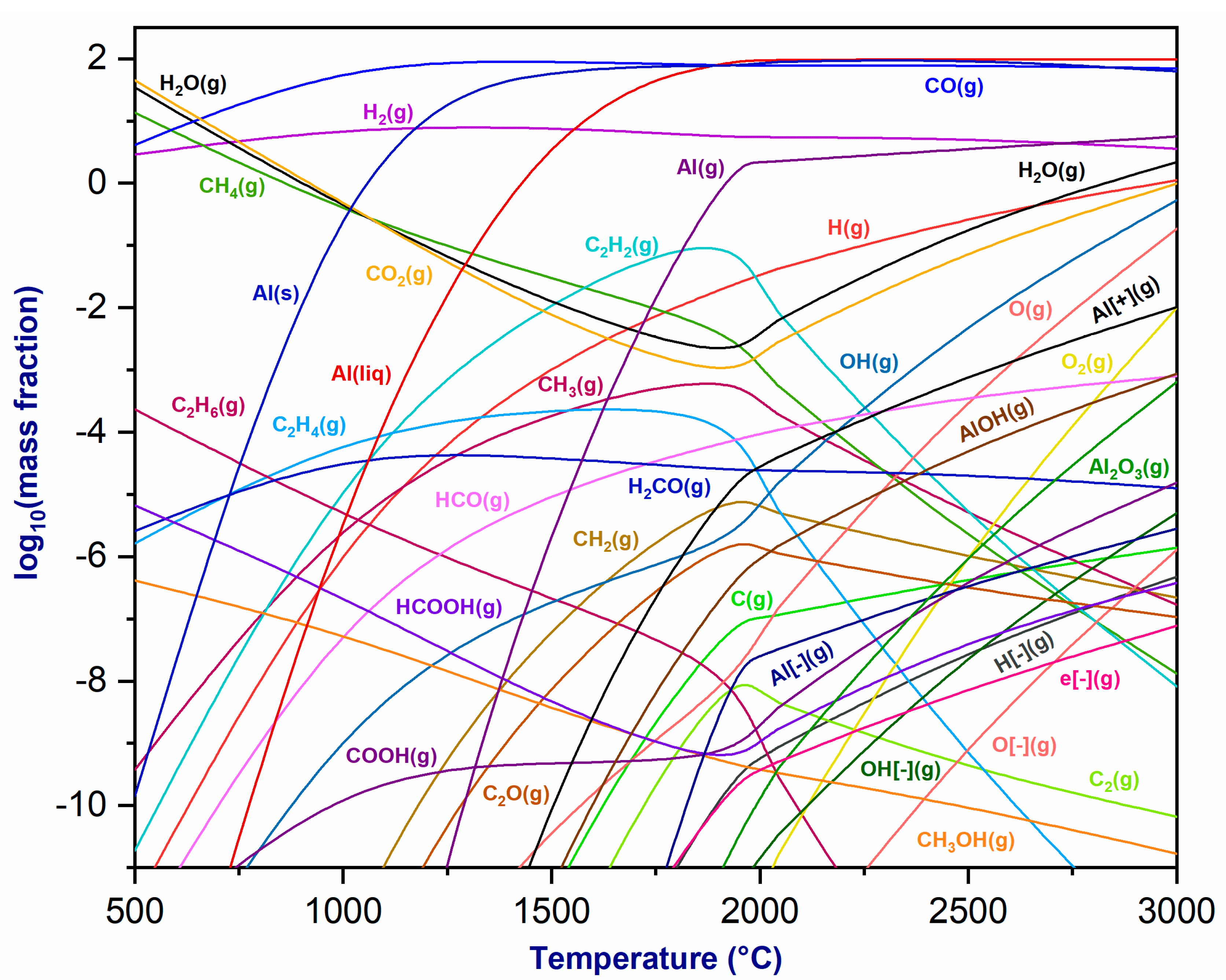
The thermodynamic equilibrium of the plasma formed by the CO2/CH4 gas combination at the torch exit and in the presence of alumina was investigated as a function of temperature. At temperatures over 1000 °C, the CO2/CH4 gas mixture principally produces CO, H2, H2O, C2H2, and O2 in the gas phase. It is important to note, however, that ion formation happens at temperatures higher than 3000 °C due to electron generation [34]. The decomposition of CH4 aims to produce carbon ions (C− and C+). These carbon ions are subsequently attracted and deposited on the negatively charged graphite cathode, completely compensating for the loss of cathode material during the plasma discharge process, hence increasing the cathode’s life [35].
Figure 2 illustrates the thermodynamic equilibrium composition diagrams of the chemical species produced by the plasma mixture and Al2O3 at varying temperatures under atmospheric pressure. As the temperature increases, the equilibrium produces CO(g) and H2(g), whose concentrations remain constant until reaching 3000 °C. CH4(g) degrades, resulting in a lower mass fraction. Simultaneously, the mass fractions of H2O(g) and CO2(g) decrease between 500 and 2000 °C after reaching their maximum. The decomposition of hydrocarbons (CH4) produces C2H2(g), with its mass fraction increasing up to 2000 °C before decreasing. Additionally, the phases Al(s) and Al(liq) form at low temperatures, at approximately 800 °C, with mass fractions rapidly rising until stabilizing around 1500 °C. Similarly, Al(g) and Al2O3(g) are generated at around 1200 °C and 1900 °C, respectively, while aluminum ions such as Al− and Al+ are produced at temperatures exceeding 1500 °C. Finally, the thermodynamic study of the equilibrium in the plasma mixture resulting from the interaction between the gases exiting the torch (H2, CO, CH4, CO2, etc.) and Al2O3 indicates that the CO2/CH4 plasma torch may be used to reduce aluminum oxide and generate metallic aluminum.
3.2.2. Titanium Oxide (TiO2)
Figure 3 depicts the thermodynamic equilibrium of the plasmagenic mixture at the torch exit and TiO2 as the temperature varies under atmospheric pressure. As the temperature increases, various chemical species form. The mass fractions of CO(g) and H2(g) remain constant, while those of CO2(g) and H2O(g) decrease up to 1000 °C, after which they experience a minor rise. The mass fraction of CH4(g) decreases with temperature due to decomposition. At lower temperatures, a Ti2O3(s) phase forms, with its fraction increasing as the temperature rises. Additionally, a TiC(s) phase forms, increasing until it reaches a plateau at 1000 °C and then declining rapidly at 1500 °C. Ti(liq) and Ti(s) are present at low temperatures, with their fractions increasing and stabilizing at 1200 °C. Moreover, TiO2(g), TiO(g), and Ti(g) form above 1000 °C, with their mass fractions increasing with temperature. In summary, the examination of the thermodynamic equilibrium of the plasma mixture and titanium oxide demonstrates the feasibility of reducing TiO2 using a CO2/CH4 plasma torch to produce titanium metal. This investigation also highlights the advantages associated with thermal plasma torches for metallurgical applications [36].
3.2.3. Iron Oxide
- a.
- Magnetite (Fe3O4)
Figure 4 depicts the thermodynamic equilibrium of the plasmageneous mixture at the torch outlet and the magnetite (Fe3O4), highlighting the reaction’s production of CO(g), H2(g), H2O(g), and CO2(g), with fractions that are slightly stable as a function of temperature. The concentration of CH4(g) drops with increasing temperature, while ferrous hydroxide Fe(OH)2(g) emerges first and increases in mass fraction as temperature rises. At around 1300 °C, oxygen O2(g) is created, and its proportion grows as the temperature rises. Fe(s) and Fe(liq) phases are also formed, with constant mass fractions. Above 700 °C, Fe(g) and FeO(g) phases are formed, with fractions increasing with temperature. Fe- and Fe+ ions appear at temperatures over 1500 °C. This demonstrates that magnetite reduction may be achieved by utilizing CO2/CH4 as a plasma gas, resulting in the formation of a highly reactive gas mixture with a carbon deposit. This carbon deposit also reacts with Fe3O4, producing Fe, FeO, and CO(g) [37].
- b.
- Hematite (Fe2O3)
Figure 5 exhibits the thermodynamic equilibrium of the plasmageneous mixture at the torch exit and its interaction with hematite (Fe2O3). This reaction system highlights the production of CO(g), H2(g), H2O(g), and CO2(g) because of the reaction, and these fractions show slight stability variations with temperature. As the temperature rises, the concentration of CH4(g) decreases, while ferrous hydroxide Fe(OH)2(g) improves prominence and experiences an increasing mass fraction. At approximately 1300 °C, oxygen O2(g) is produced, and its percentage grows with increasing temperature. Furthermore, solid and liquid iron phases, i.e., Fe(s) and Fe(liq), are produced with similar mass fractions. Beyond 700 °C, Fe(g) and FeO(g) phases and their fractions increase with temperature. Fe- and Fe+ ions emerge at temperatures over 1500 °C. Consequently, hematite can be reduced using CO2/CH4 as the plasma gas, inducing the formation of a highly reactive gas mixture composed mainly of CO and H2. Fe2O3 reacts with CO to generate Fe3O4, which is then transformed into metallic iron [38].
3.3. XRD Analysis
3.3.1. Aluminum Oxide (Al2O3)
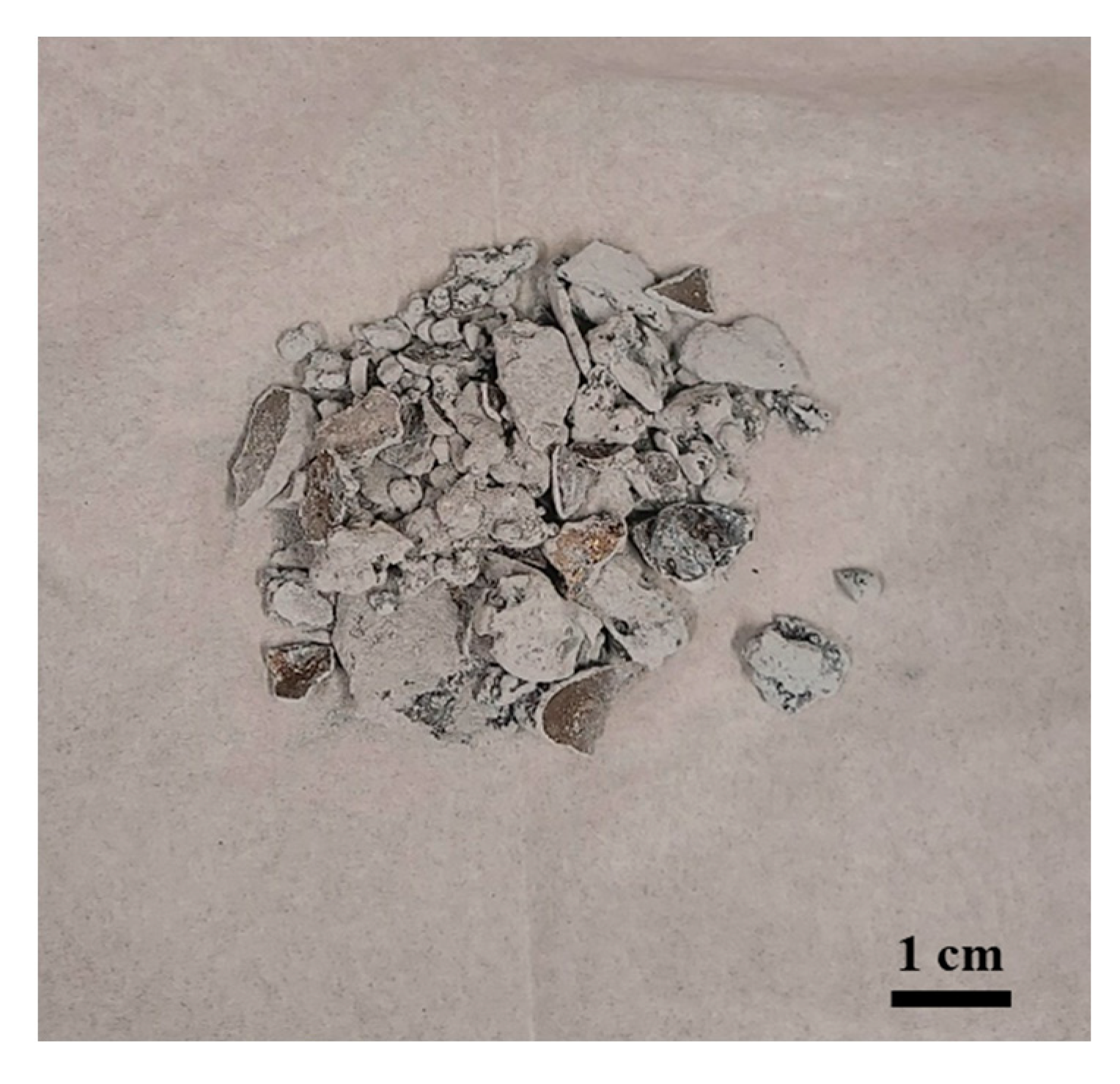
As illustrated in Figure 6, the cone component is a metallic part that includes aluminum metal and aluminum oxide surrounding the cone. For this objective, the XRD analysis was concentrated on this unique area of the set-up because of the high levels of temperatures attained in this zone and the low oxygen concentration that allows the reduction of Al2O3.
Figure 7 shows the XRD diffractograms of aluminum oxide before and after plasma treatment. Initially, the XRD analysis of the raw material displays only alumina peaks. After plasma treatment, the raw material was reduced in the plasma reactor, leaving some alumina peaks. Furthermore, metallic aluminum peaks appear near the alumina peaks, indicating that aluminum was produced at temperatures higher than 2000 °C, mainly in the cone section [39].
As the XRD spectrum demonstrates, the application of the CO2/CH4 plasma torch reduced aluminum oxide Al2O3 to its metallic state (Al metal). After plasma treatment, the material underwent a Rietveld analysis to determine the mass proportion of each phase. The results of the Rietveld analysis of Al2O3 after plasma treatment are shown in Table 2.
3.3.2. Titanium Oxide (TiO2)
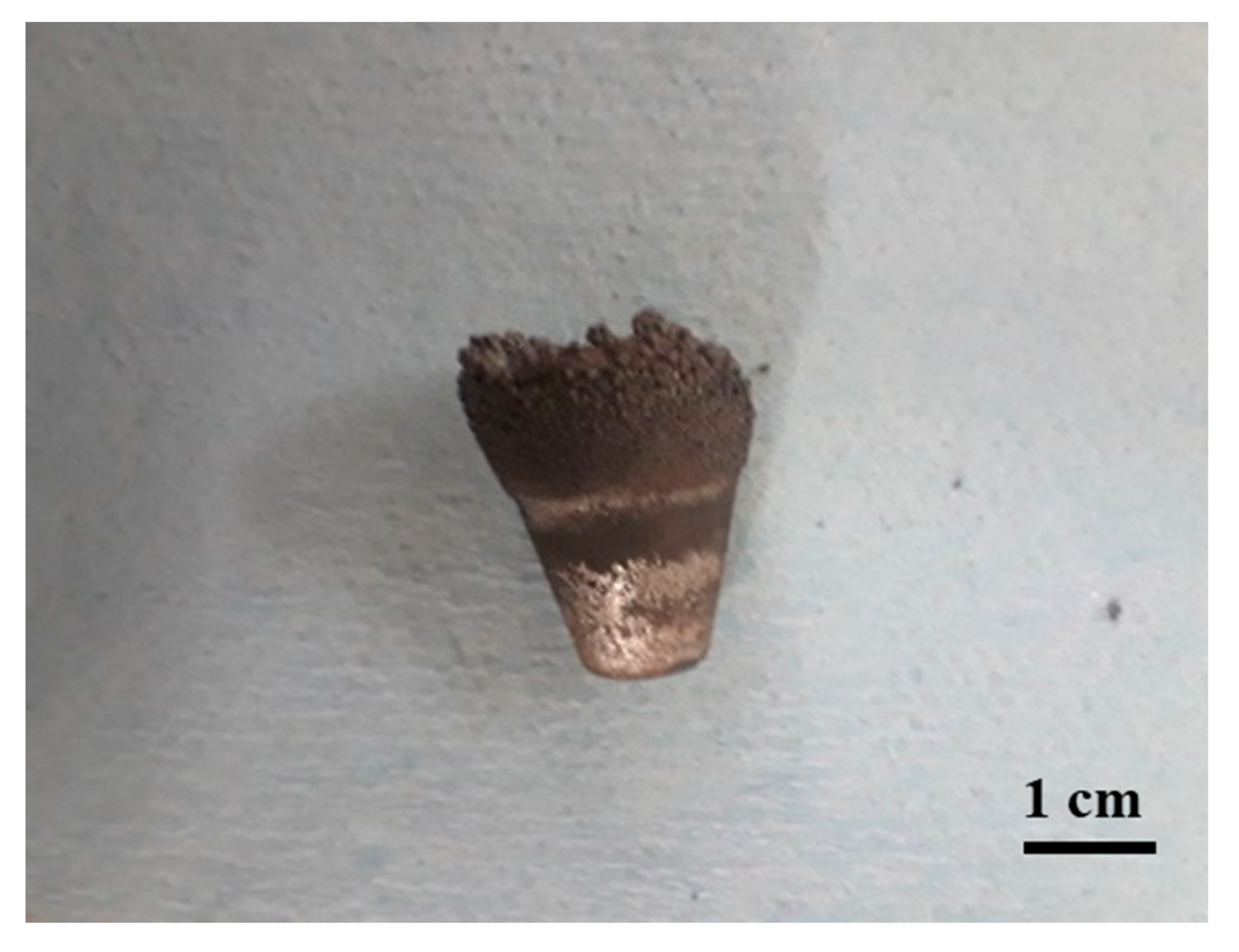
TiO2 is a complicated phase, requiring high temperatures and an oxygen-depleted atmosphere to be converted into titanium metal. The conical part, which is directly exposed to the plasma arc, reaches relatively high temperatures. Figure 8 shows the metallic cone formed because of plasma treatment.
Figure 9 shows an XRD diffractogram of TiO2 before and after plasma treatment. Diffraction peaks at 27°, 36°, and 55° in XRD patterns indicate the existence of TiO2’s rutile phase, as proven by complete agreement with the reference spectrum [40]. However, plasma exposure resulted in the formation of other oxidized forms of rutile, such as Ti3O5 and Ti5O9. This would indicate a partial reduction in TiO2 within the plasma reactor. Particular regions showed a further reduction, resulting in the production of titanium metal, as shown by the presence of matching peaks [41].
Following plasma treatment, several titanium oxide phases emerged, indicating that plasma treatment affected the rutile concentrate. Furthermore, the treated concentrate exhibited lower crystallinity than the original concentrate. A minor quantity of titanium was identified on the XRD spectrum, indicating the importance of the material’s exposure time to plasma treatment. Two minutes is insufficient time to reduce titanium oxide and produce further titanium metal. Table 3 shows the results of the Rietveld analysis, which enabled us to quantify the TiO2 phases after plasma treatment.
3.3.3. Iron Oxide
- a.
- Magnetite (Fe3O4)
Figure 10 depicts the conical section of the reactor after magnetite plasma treatment. It can be observed that the cone’s base is made of a metallic substance from which iron metal may be formed, as well as iron oxide, which covers the whole back of the cone.
Figure 11 exhibits the X-ray diffraction pattern of magnetite, which shows six diffraction peaks corresponding to the (220), (311), (400), (422), (511), and (440) crystal planes of the magnetite phase before plasma treatment [42]. Furthermore, the magnetite’s initial XRD pattern shows a few FeO peaks. After plasma treatment, Fe3O4 was reduced, which produced FeO, hematite, and metallic iron. The phase change is indicated by the presence of prominent FeO peaks in the diffraction pattern. The observed presence of peaks at 45° and 65° indicates the production of metallic iron [43]. A Rietveld analysis was performed to determine the proportion of each phase after plasma treatment. Table 4 depicts the Rietveld analysis of magnetite after plasma treatment.
- b.
- Hematite (Fe2O3)
Iron metal was formed mainly in the conical part of the reactor, where the material was in direct contact with the plasma jet. Figure 12 illustrates the configuration of the material in the cone section of the reactor.
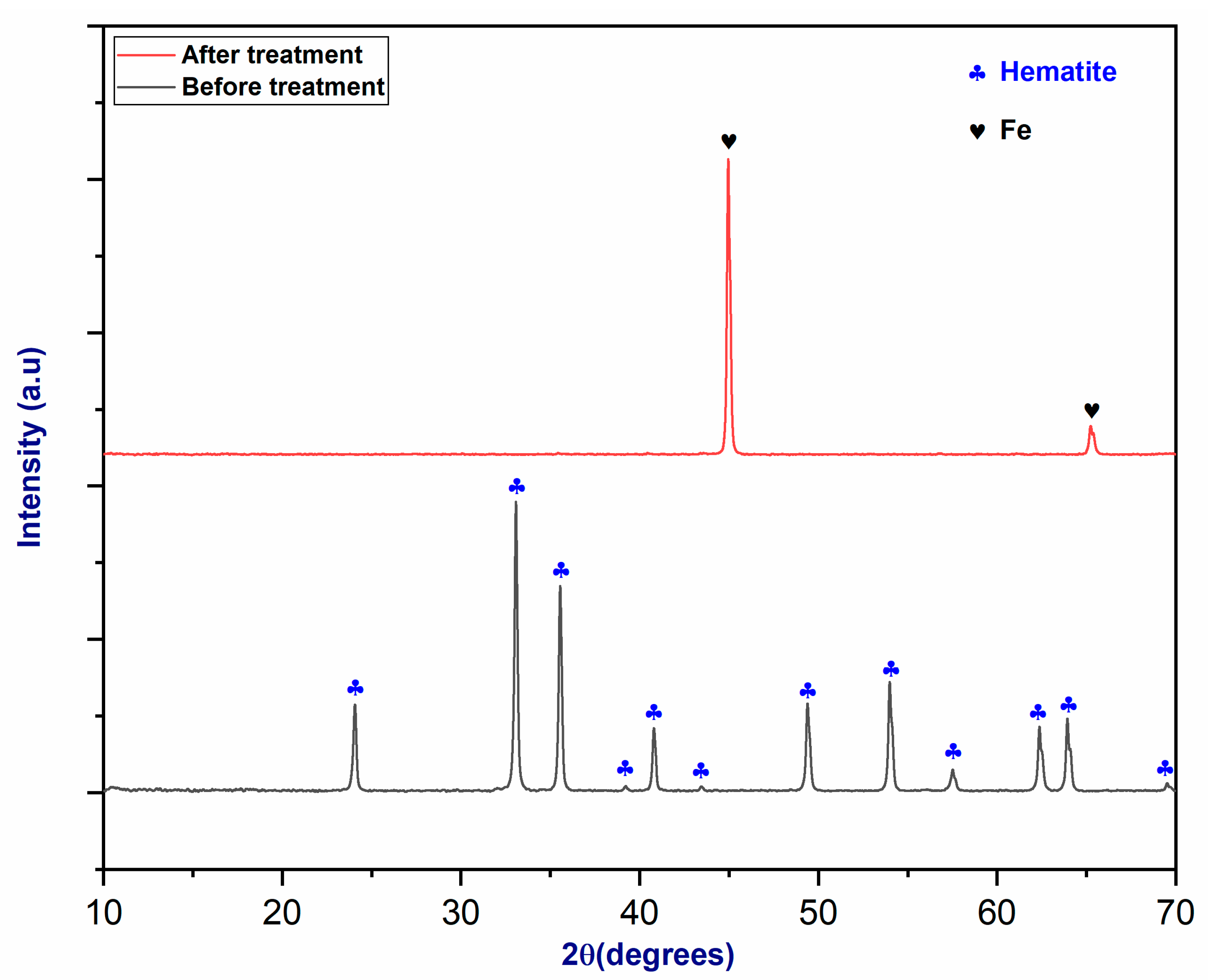
According to the XRD spectrum shown in Figure 13, the peaks associated with the raw material correspond to the hematite structure [44]. Following plasma treatment, hematite was reduced to metallic iron in the conical section of the reactor, where the partial pressure of oxygen was very low and the temperature reached over 3000 °C [45]. As in the previous example with magnetite, the observation of peaks at 45° and 65° indicates the production of metallic iron [46].
3.3.4. Oxide Mixture (Iron Oxide + Titanium Oxide)
Figure 14 depicts the XRD diffractogram of the oxide mixture. During the thermal plasma treatment of a rutile–magnetite combination in a spouted bed reactor, local production of Ti and Fe metals occurred. The solidification of the metal cone led to a noticeable separation of iron and titanium. While the purity of the iron was confirmed, the presence of oxygen and other impurities in the reactor suggests that the reaction was incomplete due to the experiment’s short duration, as indicated by the hot spots generated on the reactor’s conical section. Although pseudobrookite predominates in the oxide mixture, this implies that only a portion of the entire mixture was reduced.
The capability to reduce a combination of oxides remains a significant advantage of the CO2/CH4 plasma torch. The results presented below are preliminary and are still in the development stage. A new reactor design is required to extend exposure duration and achieve higher temperatures within the reactor chamber. A Rietveld analysis was employed to ascertain the proportion of each phase in the oxide mixture following plasma treatment. The findings are detailed in Table 5.
3.4. SEM–EDS Analysis
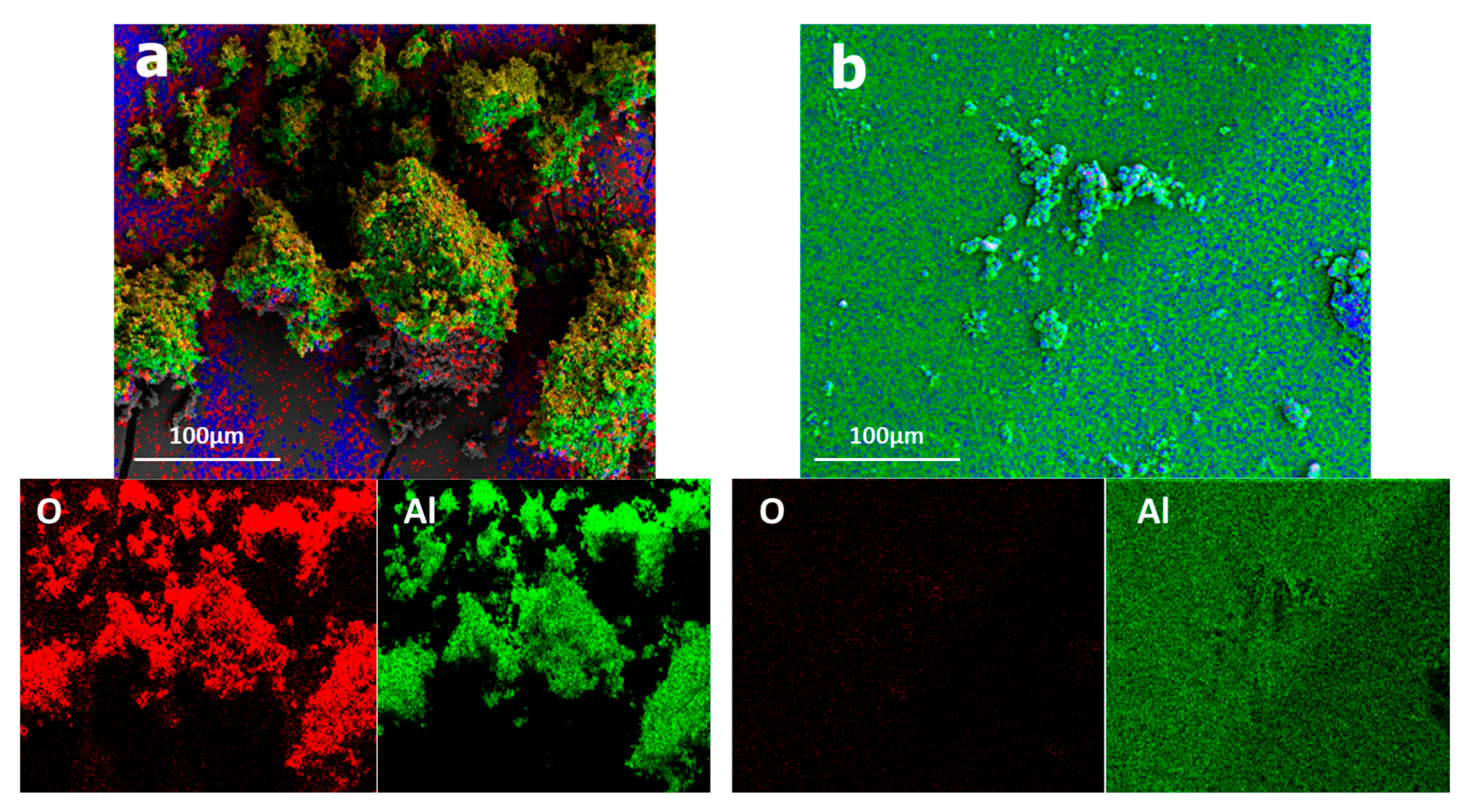
Figure 15 illustrates the elemental distribution of Al2O3 before and after plasma treatment. After plasma treatment, aluminum metal production was seen in the reactor’s conical part, as shown by the XRD analysis. SEM–EDS analysis indicated that the elements present before plasma treatment were aluminum and oxygen, with a high concentration of the latter. However, after plasma treatment, the oxygen content decreased significantly, indicating the existence of a distinct aluminum phase.
Thus, plasma has a promising future as an efficient method for alumina reduction. However, it is critical to emphasize that further research and development efforts are necessary in this sector before this technology can be fully realized [35].
The CO2/CH4 plasma torch was used for reducing titanium oxide into titanium metal, producing relatively little oxygen throughout the treatment process. The total time of the treatment was also significant since the rate of reduction increased while the material remained in contact with the plasma. Treatment duration is thus critical. Figure 16 depicts the elemental composition of titanium oxide before and after plasma treatment.
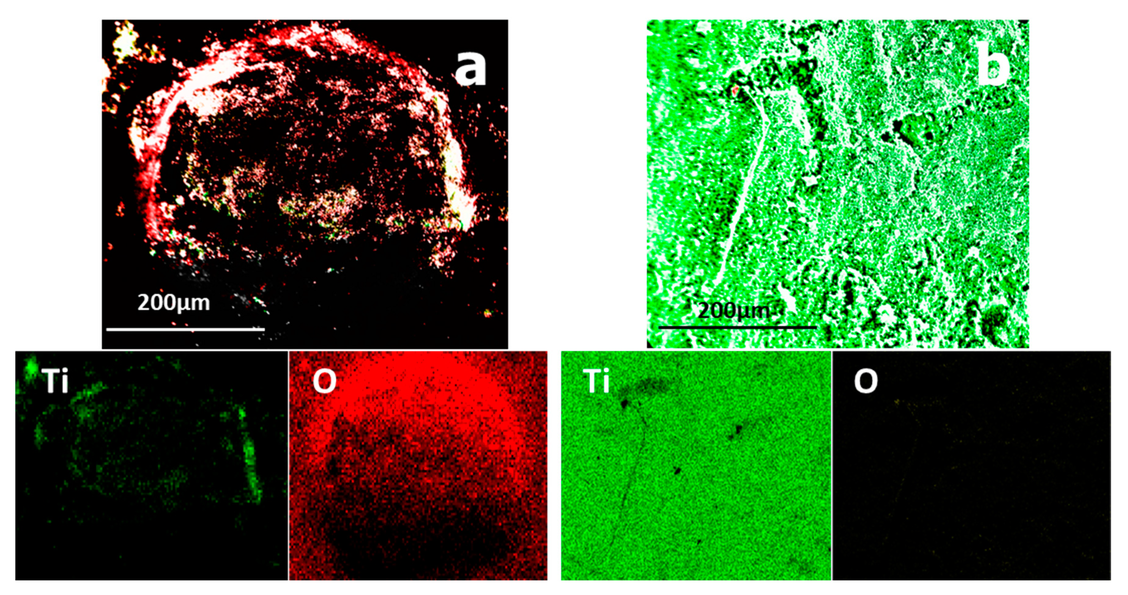
Figure 17 shows the elemental distribution of iron oxide before and after treatment. After plasma treatment, the oxygen concentration was reduced because the cone part might have gotten quite hot and the iron might have melted and separated from the other components. Plasma treatment may easily produce metallic iron as long as the quantity of oxygen in the reactor is kept low.
3.5. Mass Balance
A mass balance serves as a crucial tool for determining and documenting the mass of inputs and outputs within a system, as well as any changes in these masses over time [35]. This concept is grounded in the principle of “conservation of mass”, which states that the total quantity of mass within a closed system remains constant. Maintaining careful attention to mass balance is essential for enhancing output and meeting relevant criteria [47]. Table 6 provides a summary of the preliminary mass balance findings from the research.
4. Conclusions
In various sectors, the quest for tools that combine high efficiency with low cost has become crucial. Plasma technology stands out as one such tool, developed for a multitude of applications, particularly in material processing. This study took an innovative approach, using a new DC plasma torch for reducing oxides such as alumina, iron oxide, and titanium oxide. The fundamental aim of this research is to demonstrate the feasibility of this oxide reduction method using a plasma torch powered by greenhouse gases such as CO2 and CH4. This study stands out for its innovative exploration of the use of this specific type of plasma torch for the reduction of specific oxides, an approach that had never been attempted before. The conical portion of the plasma reactor proved critical in preventing overheating, thus reducing processing time. This innovative approach successfully reduced a wide range of oxides, including alumina, hematite, magnetite, and rutile, and their mixtures. The thermodynamic investigation confirmed the production of many chemical species, indicating that pure metals might be produced utilizing the CO2/CH4 mixture as a plasmagenic gas. XRD and SEM–EDS studies were used to investigate the reduction of alumina, hematite, magnetite, and rutile. The results show that in the reactor’s conical section, titanium oxide is partially reduced, and a small amount of titanium is produced, while aluminum oxide and iron oxide (magnetite and hematite) are reduced to produce aluminum and iron metal, respectively. The significant variation in oxygen levels before and after treatment confirms the XRD studies, achieved by using the plasma torch’s power as a successful tool for oxide reduction. The oxide mixtures also showed encouraging results, allowing the separation of pure metals such as iron and titanium. Regarding plasma composition, a detailed analysis utilizing mass spectrometry and thermodynamic calculations showed that CH4 and CO2 decompose into H2 and CO. This process paves the way for an innovative procedure that promises to significantly reduce the environmental footprint associated with the thermal treatment of oxides. Using these greenhouse gases for reduction avoids generating new emissions, thereby mitigating adverse environmental impacts. Despite these hopeful findings, further research and development in this area are needed before this technology can realize its full potential.
Author Contributions
Conceptualization, M.E.K. and G.S.; formal analysis, M.E.K.; investigation, M.E.K.; methodology, M.E.K.; funding acquisition, G.S.; resources, G.S.; supervision, G.S.; validation, M.E.K.; writing—original draft preparation, M.E.K.; writing—review and editing, M.E.K. and G.S. All authors have read and agreed to the published version of the manuscript.
Funding
The financial support for this research was provided through the NSERC (Natural Sciences and Engineering Research Council of Canada) Discovery Grant (RGPIN-2018-06128) and by the Metchib company based in Quebec, Canada.
Data Availability Statement
Data are contained within the article.
Acknowledgments
We would like to express our gratitude to the Metchib company for its generous support of all kinds.
Conflicts of Interest
The authors declare no conflicts of interest.
References
- Philibert, J.; Vignes, A.; Bréchet, Y.; Combrade, P. Metallurgie, du minerai au materiau. Ann. De Chim.-Sci. Des Mater. 1999, 24, 404. [Google Scholar] [CrossRef]
- Sabat, K.C.; Rajput, P.; Paramguru, R.K.; Bhoi, B.; Mishra, B.K. Reduction of Oxide Minerals by Hydrogen Plasma: An Overview. Plasma Chem. Plasma Process. 2014, 34, 1–23. [Google Scholar] [CrossRef]
- Samal, S. Thermal plasma technology: The prospective future in material processing. J. Clean. Prod. 2017, 142, 3131–3150. [Google Scholar] [CrossRef]
- Dessemond, C.; Soucy, G.; Laroche, N. Reductive thermal plasma conversion of a spodumene concentrate and impact on lithium extraction. Miner. Eng. 2024, 211, 108682. [Google Scholar] [CrossRef]
- Kogelschatz, U. Atmospheric-pressure plasma technology. Plasma Phys. Control. Fusion 2004, 46, B63. [Google Scholar] [CrossRef]
- Chanturia, V.A.; Bunin, I.Z.; Ryazantseva, M.V. The Low-Temperature Plasma Effect of Dielectric Barrier Discharge on Physicochemical and Process Properties of Natural Iron Sulfides. J. Min. Sci. 2023, 59, 621–627. [Google Scholar] [CrossRef]
- Chanturiya, V.A.; Bunin, I.Z. Advances in Pulsed Power Mineral Processing Technologies. Minerals 2022, 12, 1177. [Google Scholar] [CrossRef]
- Samal, S. Thermal Plasma Processing of Ilmenite; Springer: Berlin/Heidelberg, Germany, 2017. [Google Scholar]
- Ojebuobon, F.K.; Martins, G.P. Thermal plasma technology in the extractive metallurgy of titanium, refractory metals: Extractions, processing and applications. The Minerals. Met. Mater. Soc. 1990, 101. [Google Scholar]
- Lanyon, M.R.; Lwin, T.; Merritt, R.R. The dissolution of iron in the hydrochloric acid leach of an ilmenite concentrate. Hydrometallurgy 1999, 51, 299–323. [Google Scholar] [CrossRef]
- Heberlein, J.; Murphy, A.B. Thermal plasma waste treatment. J. Phys. D Appl. Phys. 2008, 41, 053001. [Google Scholar] [CrossRef]
- Sikarwar, V.S.; Mašláni, A.; Hlína, M.; Fathi, J.; Mates, T.; Pohořelý, M.; Meers, E.; Šyc, M.; Jeremiáš, M. Thermal plasma assisted pyrolysis and gasification of RDF by utilizing sequestered CO2 as gasifying agent. J. CO2 Util. 2022, 66, 102275. [Google Scholar] [CrossRef]
- Sikarwar, V.S.; Mašláni, A.; Van Oost, G.; Fathi, J.; Hlína, M.; Mates, T.; Pohořelý, M.; Jeremiáš, M. Integration of thermal plasma with CCUS to valorize sewage sludge. Energy 2024, 288, 129896. [Google Scholar] [CrossRef]
- Hrabovsky, M.; Hlina, M.; Kopecky, V.; Maslani, A.; Zivny, O.; Krenek, P.; Serov, A.; Hurba, O. Steam plasma treatment of organic substances for hydrogen and syngas production. Plasma Chem. Plasma Process. 2017, 37, 739–762. [Google Scholar] [CrossRef]
- Sarafraz, M.M.; Christo, F.C.; Rolfe, B.; Shabani, B.; Tran, N.N.; Fulcheri, L.; Escribà-Gelonch, M.; Hessel, V. Thermal plasma-driven looping for metal scrap processing with hydrogen. Energy Convers. Manag. 2024, 299, 117800. [Google Scholar] [CrossRef]
- Sikarwar, V.S.; Reichert, A.; Pohorely, M.; Meers, E.; Ferreira, N.L.; Jeremias, M. Equilibrium modeling of thermal plasma assisted co-valorization of difficult waste streams for syngas production. Sustain. Energy Fuels 2021, 5, 4650–4660. [Google Scholar] [CrossRef]
- Safa, S.; Soucy, G. Liquid and solution treatment by thermal plasma: A review. Int. J. Environ. Sci. Technol. 2014, 11, 1165–1188. [Google Scholar] [CrossRef]
- Chen, L.; Pershin, L.; Mostaghimi, J. A New Highly Efficient High-Power DC Plasma Torch. IEEE Trans. Plasma Sci. 2008, 36, 1068–1069. [Google Scholar] [CrossRef]
- Mitrasinovic, A.; Pershin, L.; Mostaghimi, J. Electronic Waste Treatment by High Enthalpy Plasma Jet; International Plasma Chemistry Society (IPCS20): Philadelphia, PA, USA, 2013; pp. 1–4. [Google Scholar]
- Safa, S.; Hekmat-Ardakan, A.; Soucy, G. Comparison of CO2and oxygen DC submerged thermal plasmas for decomposition of carboxylic acid in aqueous solution. J. Phys. Conf. Ser. 2014, 550, 012015. [Google Scholar] [CrossRef]
- Verozub, E.Y.; Miringof, N.S.; Zvyagintsev, K.N.; Yur’ev, Y.M.; Shchedrov, S.A.; Volkov, A.V.; Cherepov, P.V.; Mezentsev, E.P.; Simonov, K.V.; Sukhoteplov, V.N.; et al. Performance analysis of gas-burner equipment of rotary kilns for calcining magnesite. Refractories 1975, 16, 355–359. [Google Scholar] [CrossRef]
- Wu, K.-K.; Chang, Y.-C.; Chen, C.-H.; Chen, Y.-D. High-efficiency combustion of natural gas with 21–30% oxygen-enriched air. Fuel 2010, 89, 2455–2462. [Google Scholar] [CrossRef]
- Boulos, M.I.; Fauchais, P.L.; Pfender, E. The plasma state. In Handbook of Thermal Plasmas; Springer: Berlin/Heidelberg, Germany, 2023; pp. 3–55. [Google Scholar]
- Kobayashi, A.; Osaki, K.; Yamabe, C. Treatment of CO2 gas by high-energy type plasma. Vacuum 2002, 65, 475–479. [Google Scholar] [CrossRef]
- Boulos, M.I.; Fauchais, P.; Pfender, E. Thermal Plasmas: Fundamentals and Applications; Springer Science & Business Media: Berlin/Heidelberg, Germany, 2013. [Google Scholar]
- León-Reina, L.; García-Maté, M.; Álvarez-Pinazo, G.; Santacruz, I.; Vallcorba, O.; De la Torre, A.G.; Aranda, M.A.G. Accuracy in Rietveld quantitative phase analysis: A comparative study of strictly monochromatic Mo and Cu radiations. J. Appl. Crystallogr. 2016, 49, 722–735. [Google Scholar] [CrossRef] [PubMed]
- Laflamme, C.B. Synthèse de Poudres Ultrafines de Carbure de Silicium Dans un Réacteur à Plasma à Courant Continu. Ph.D. Thesis, Universite de Sherbrooke, Sherbrooke, QC, Canada, 1991. [Google Scholar]
- Harvey, J.-P.; Lebreux-Desilets, F.; Marchand, J.; Oishi, K.; Bouarab, A.-F.; Robelin, C.; Gheribi, A.E.; Pelton, A.D. On the Application of the FactSage Thermochemical Software and Databases in Materials Science and Pyrometallurgy. Processes 2020, 8, 1156. [Google Scholar] [CrossRef]
- Sang, L.; Lv, X.; Wu, Y. NaNO3-KNO3-KCl/K2CO3 with the elevated working temperature for CSP application: Phase diagram calculation and machine learning. Sol. Energy 2023, 252, 322–329. [Google Scholar] [CrossRef]
- Perry, D.W.G.R.H. Perry’s Chemical Engineers’ Handbook; McGraw-Hill: New York, NY, USA, 1984. [Google Scholar] [CrossRef]
- Bird, R.B. Transport phenomena. Appl. Mech. Rev. 2002, 55, R1–R4. [Google Scholar] [CrossRef]
- Baehr, H.D.; Stephan, K. Heat and Mass Transfer; Springer: Berlin/Heidelberg, Germany, 2006. [Google Scholar]
- Taler, D.; Taler, J. Simplified analysis of radiation heat exchange in boiler superheaters. Heat Transf. Eng. 2009, 30, 661–669. [Google Scholar] [CrossRef]
- Safa, S.; Soucy, G. Decomposition of high molecular weight carboxylic acid in aqueous solution by submerged thermal plasma. Chem. Eng. J. 2014, 244, 178–187. [Google Scholar] [CrossRef]
- El Khalloufi, M.; Soucy, G.; Lapointe, J.; Paquet, M. Reduction of an ilmenite concentrate by using a novel CO2/CH4 thermal plasma torch. Minerals, 2024. [Google Scholar]
- Rao, L.; Rivard, F.; Carabin, P. Thermal plasma torches for metallurgical applications. In 4th International SYMPOSIUM on High-Temperature Metallurgical Processing; John Wiley & Sons, Inc.: Hoboken, NJ, USA, 2013; p. 57. [Google Scholar]
- Zhou, M.; Jiang, T.; Ding, X.; Ma, S.; Wei, G.; Xue, X. Thermodynamic study of direct reduction of high-chromium vanadium–titanium magnetite (HCVTM) based on phase equilibrium calculation model. J. Therm. Anal. Calorim. 2019, 136, 885–892. [Google Scholar] [CrossRef]
- Chen, H.; Zheng, Z.; Chen, Z.; Bi, X.T. Reduction of hematite (Fe2O3) to metallic iron (Fe) by CO in a micro fluidized bed reaction analyzer: A multistep kinetics study. Powder Technol. 2017, 316, 410–420. [Google Scholar] [CrossRef]
- Zhang, M.; Kamavarum, V.; Reddy, R.G. New electrolytes for aluminum production: Ionic liquids. JOM 2003, 55, 54–57. [Google Scholar] [CrossRef]
- Thamaphat, K.; Limsuwan, P.; Ngotawornchai, B. Phase characterization of TiO2 powder by XRD and TEM. Agric. Nat. Resour. 2008, 42, 357–361. [Google Scholar]
- Jiao, S.; Zhu, H. Novel metallurgical process for titanium production. J. Mater. Res. 2006, 21, 2172–2175. [Google Scholar] [CrossRef]
- Ouyang, Z.-W.; Chen, E.-C.; Wu, T.-M. Thermal Stability and Magnetic Properties of Polyvinylidene Fluoride/Magnetite Nanocomposites. Materials 2015, 8, 4553–4564. [Google Scholar] [CrossRef] [PubMed]
- Liu, S.; Wang, L. Controlled Preparation of Different Proportions of Metal Fe-Mn from Waste Mn Ferrite by Molten Salt Electrolysis. Processes 2020, 8, 1647. [Google Scholar] [CrossRef]
- Zainuri, M. Hematite from Natural Iron Stones as Microwave Absorbing Material on X-Band Frequency Ranges. IOP Conf. Ser. Mater. Sci. Eng. 2017, 196, 012008. [Google Scholar] [CrossRef]
- Yu, J.; Han, Y.; Li, Y.; Gao, P.; Li, W. Mechanism and Kinetics of the Reduction of Hematite to Magnetite with CO–CO2 in a Micro-Fluidized Bed. Minerals 2017, 7, 209. [Google Scholar] [CrossRef]
- Gonoring, T.B.; Franco, A.R.; Vieira, E.A.; Nascimento, R.C. Kinetic analysis of the reduction of hematite fines by cold hydrogen plasma. J. Mater. Res. Technol. 2022, 20, 2173–2187. [Google Scholar] [CrossRef]
- Dai, Z.; Bos, J.-A.; Lee, A.; Wells, P. Mass balance and mineralogical analysis of flotation plant survey samples to improve plant metallurgy. Miner. Eng. 2008, 21, 826–831. [Google Scholar] [CrossRef]
Figure 1.
Schematic drawing of the experimental set-up.

Figure 2.
Thermodynamic equilibrium of plasmagenic CO2/CH4 mixture with alumina (Al2O3) at P = 1 atm.
Figure 2.
Thermodynamic equilibrium of plasmagenic CO2/CH4 mixture with alumina (Al2O3) at P = 1 atm.

Figure 3.
Thermodynamic equilibrium of plasmagenic CO2/CH4 mixture with titanium oxide (TiO2) at P = 1 atm.
Figure 3.
Thermodynamic equilibrium of plasmagenic CO2/CH4 mixture with titanium oxide (TiO2) at P = 1 atm.

Figure 4.
Thermodynamic equilibrium of plasmagenic CO2/CH4 mixture with magnetite (Fe3O4) at P = 1 atm.
Figure 4.
Thermodynamic equilibrium of plasmagenic CO2/CH4 mixture with magnetite (Fe3O4) at P = 1 atm.

Figure 5.
Thermodynamic equilibrium of plasmagenic CO2/CH4 mixture with hematite (Fe2O3) at P = 1 atm.
Figure 5.
Thermodynamic equilibrium of plasmagenic CO2/CH4 mixture with hematite (Fe2O3) at P = 1 atm.

Figure 6.
The cone part of alumina after plasma treatment.

Figure 7.
The XRD patterns of alumina (Al2O3) before and after plasma treatment.

Figure 8.
The cone part of rutile (TiO2) after plasma treatment.

Figure 9.
The XRD pattern of rutile (TiO2) before and after plasma treatment.

Figure 10.
The cone part of magnetite after plasma treatment.

Figure 11.
The XRD pattern of magnetite before and after plasma treatment.

Figure 12.
The cone part of hematite after plasma treatment.

Figure 13.
The XRD pattern of hematite before and after plasma treatment.

Figure 14.
The XRD pattern of oxide mixture (TiO2 + Fe3O4) after plasma treatment.

Figure 15.
Elementary repartition of alumina elements (a) before plasma treatment and (b) after plasma treatment.
Figure 15.
Elementary repartition of alumina elements (a) before plasma treatment and (b) after plasma treatment.

Figure 16.
Elementary repartition of TiO2 elements before plasma treatment (a) and after plasma treatment (b).
Figure 16.
Elementary repartition of TiO2 elements before plasma treatment (a) and after plasma treatment (b).

Figure 17.
Elementary repartition of iron oxide elements (a) before plasma treatment and (b) after plasma treatment.
Figure 17.
Elementary repartition of iron oxide elements (a) before plasma treatment and (b) after plasma treatment.


Table 1.
The gas quantity at the outlet of the plasma torch (mass spectrometer analysis).
| H2 | CO | CH4 | CO2 | C2H2 | H2O | O2 | |
|---|---|---|---|---|---|---|---|
| Quantity (mole) | 0.4 | 0.5 | 0.4 | 0.4 | 0.4 | 0.4 | 0.006 |
Table 2.
Rietveld analysis of Al2O3 after plasma treatment.
| Phase | Wt.% (±2) |
|---|---|
| Al2O3 | 45.4 |
| Al | 54.6 |
Table 3.
Rietveld analysis of TiO2 after plasma treatment.
| Phase | Wt.% (±2) |
|---|---|
| TiO2 | 8.4 |
| Ti3O5 | 35.4 |
| Ti5O9 | 54.8 |
| Ti | 1.4 |
Table 4.
Rietveld analysis of Fe3O4 after plasma treatment.
| Phase | Wt.% (±2) |
|---|---|
| FeO | 45.7 |
| Fe | 49.7 |
| Fe2O3 | 4.3 |
| Fe3O4 | 0.3 |
Table 5.
Rietveld analysis of an oxide mixture after plasma treatment.
| Phase | Wt.% (±2) |
|---|---|
| Pseudobrookite (FeTi2O5) | 60.2 |
| Ilmenite (FeTiO3) | 26.0 |
| TiO2 | 1.0 |
| Fe | 5.6 |
| Ti | 7.2 |
Table 6.
Mass balance summary.
| Raw Material | M0 (g) | Reactor + Cone Part | Filter Part | Recovery (%) |
|---|---|---|---|---|
| Al2O3 | 300 | 285 | 6 | 97 |
| TiO2 | 300 | 276 | 2 | 92 |
| Fe2O3 | 300 | 250 | 6 | 85 |
| Fe3O4 | 300 | 253 | 4 | 86 |
| TiO2 + Fe3O4 | 300 | 230 | 8.5 | 80 |
Disclaimer/Publisher’s Note: The statements, opinions and data contained in all publications are solely those of the individual author(s) and contributor(s) and not of MDPI and/or the editor(s). MDPI and/or the editor(s) disclaim responsibility for any injury to people or property resulting from any ideas, methods, instructions or products referred to in the content. |
© 2024 by the authors. Licensee MDPI, Basel, Switzerland. This article is an open access article distributed under the terms and conditions of the Creative Commons Attribution (CC BY) license (https://creativecommons.org/licenses/by/4.0/).
Share and Cite
MDPI and ACS Style
El Khalloufi, M.; Soucy, G. Oxide Reduction Treatment with a Thermal Plasma Torch: A Case Study. Minerals 2024, 14, 443. https://doi.org/10.3390/min14050443
AMA Style
El Khalloufi M, Soucy G. Oxide Reduction Treatment with a Thermal Plasma Torch: A Case Study. Minerals. 2024; 14(5):443. https://doi.org/10.3390/min14050443
Chicago/Turabian StyleEl Khalloufi, Mohammed, and Gervais Soucy. 2024. "Oxide Reduction Treatment with a Thermal Plasma Torch: A Case Study" Minerals 14, no. 5: 443. https://doi.org/10.3390/min14050443
Note that from the first issue of 2016, this journal uses article numbers instead of page numbers. See further details here.