Article

Optimization of Acid Leaching of Rare-Earth Elements from Mongolian Apatite-Based Ore

1
Department of Energy Resources Engineering, Seoul National University, Seoul 08826, Korea
2
Department of Materials and Metallurgical Engineering, South Dakota School of Mines and Technology, Rapid City, SD 57701-3995, USA
*
Author to whom correspondence should be addressed.
Minerals 2016, 6(3), 63; https://doi.org/10.3390/min6030063
Submission received: 31 March 2016 / Revised: 1 June 2016 / Accepted: 24 June 2016 / Published: 30 June 2016

Abstract

:
Optimization of the acid leaching process for Mongolian apatite-based ore containing rare-earth elements (REEs) was studied. The ore contained approximately 10% of REEs as total rare earth oxides, and the major impurities were Ca (33% as CaO) and Fe (23% as Fe2O3). Fe bearing minerals could be removed by passing the sample through a wet high-intensity magnetic separator before leaching. After magnetic separation, basic leaching tests were conducted to investigate the influence of the acid type and concentration, temperature, and the pH on the REE leaching level and kinetics. Hydrochloric acid was found to be the most effective leaching agent, leaching more than 90% of REEs in an hour. However, the concentrations of Ca ions in the leachate were also high, which would complicate recovery of the REEs. Therefore, to reduce the amount of Ca ions in the leachate, a two-stage leaching procedure was attempted. In stage 1, the sample was preleached using 1.0 M hydrochloric acid to dissolve Ca. In stage 2, the solid residue of stage 1 was leached using 2.0 M hydrochloric acid to dissolve REEs. Consequently, this two-stage leaching significantly reduced the Ca concentration in the final leachate without affecting the leaching levels of REEs.

Graphical Abstract

1. Introduction

With increasing demand for rare-earth elements (REEs) and the corresponding recent surge in their prices, many countries have begun to reevaluate old rare-earth mining prospects and explore new ones. According to a 2009 estimate by the U.S. Geological Survey, Mongolia has 31 million tonnes of rare-earth reserves (approximately 17% of the world’s total), exceeded only by China [1]. In light of Chinese restrictions on REE exportation, Mongolia has become a leading contender in the current rush for REE resources [1]. At present, Mongolia plans to increase its transportation infrastructure to ship mineral resources to Russia and the Far East [1]. Therefore, Mongolian resources potentially represent a major supply of REEs for Korea.
The REE ore deposit currently under investigation is located in southern Mongolia and contains over 300,000 t of rare-earth oxides (REOs) as combined REOs according to a recent exploration campaign [2]. The average REO grade in this area is 1.36% but reaches 6.15% in a newly discovered high-grade zone. This deposit consists of sheet-like magnetite–apatite ore bodies [3].
REE ores are usually processed in two steps: physical concentration and leaching. The first step typically includes crushing the ore and physically separating the REOs from the ore. This separation process dramatically increases the percentage of REOs in the working material but is successful only if the REEs are largely concentrated in a single mineral phase such as a form of bastnäsite (REECO3F) or monazite (REEPO4) [4]. Unfortunately, this is not the case for the REE ore under investigation, which contains primarily apatite [Ca10(PO4)6(OH,F,Cl)2] as the major source mineral. REEs in apatite usually occur as ionic substitutions for Ca within the crystal lattice rather than in discrete mineral form [5,6,7]. Intuitively, it is possible to obtain REE concentrates by selective separation of REE-bearing apatite from the ore. Froth flotation is a common process applied to phosphate ores. Consequently, various flotation tests were conducted in an attempt to obtain REE concentrates. However, the results were not satisfactory, yielding either a low recovery and/or little REE enrichment in the concentrates. Other physical concentration methods such as gravity separation and magnetic separation were also found to be ineffective in concentrating REEs, but magnetic separation showed positive effects on impurity removal.
The extraction of REEs from ore usually involves decomposition with acidic or alkaline reagents. In the acid route, acid baking is commonly used for the major REE minerals including monazite, bastnäsite, and xenotime. The treatment involves mixing REE concentrates with sulfuric acid followed by baking at around 200 °C. The resulting cake is leached with water to dissolve REEs. Alkaline digestion is typically used for monazite. The ore is decomposed with NaOH to produce rare earth hydroxides. The resulting products are then leached using hydrochloric acid to dissolve REEs. In addition, direct decomposition by HCl is another common method used for carbonate minerals such as bastnäsite.
Several studies have examined the acid leaching of REE apatite [8,9,10,11,12]. It was reported that apatite leached well in hydrochloric or nitric acid [8,10,11], but it was very difficult to attack with sulfuric acid unless the concentration and/or temperature were very high [8,10,12]. However, owing to the complex metallurgy of REEs, there is no standard process for leaching REE-bearing minerals. The choice of decomposition method depends on the mineralogy of the REE-containing phases as well as other non-REE minerals present in the ore that often affect the effectiveness of the leaching process.
This study investigates the leaching behavior of a Mongolian REE ore in response to various acids. To reduce impurities in the leachate, pre-removal of Fe by magnetic separation and a two-stage leaching process for selective removal of Ca were studied. The specific objectives were to examine the mineralogical characteristics of the sample, determine the effects of the acid type and concentration, temperature, and the pH on the leaching efficiency, and assess the optimum conditions of the leaching process for this apatite-based ore.

2. Materials and Methods

2.1. Mineralogical Characteristics of the Sample

The sample was collected from the southern region of Mongolia. Previous studies reported that the REE deposit consists of apatite ore bodies including apatite, barian celestite, magnetite, hematite, goethite, fluorite, gypsum, phlogopite, carbonate (mostly calcite), pyrite, and monazite-(Ce) [3,13]. The chemical composition of the sample was analyzed by X-ray fluorescence (XRF) and summarized in Table 1. The total level of REOs is approximately 10%. The most abundant REE is Ce, followed by La, Nd, Pr, and Y.
X-ray diffraction (XRD) (D/MAX-2500V/PC, Rigaku, Tokyo, Japan) was used to characterize the mineral phases in the sample. As shown in Figure 1, the main minerals were identified as apatite and silicate minerals. Minor minerals were goethite, hematite, maghemite, quartz, monazite, and so on.
Detailed mineralogical characterization of the ore was conducted by Enkhbayar et al. [14], who found that REEs were mostly associated with fluorapatite and hydroxyapatite. As shown in Figure 2, the apatite grains have hexagonal structures with a layered arrangement of outer crystals grown upon an inner layer of crystals. Electron probe microanalysis revealed that the REE (Ce2O3 + La2O3 + Nd2O3) content increases from the center to the edge of the specimen (9.45 wt % in mh21, 12.51 wt % in mh23, 45.57 wt % in mh24). The Si and Na contents also increased from the center to the edge of the structure. Conversely, the amounts of P and Ca decreased from the center to the edge of the sample. These trends indicate that more REE was substituted for Ca in apatite as the crystals grew. Monazite crystals were also found between the two outer layers. Therefore, it can be expected that the leaching rate would initially be high owing to the presence of a high-grade REE layer in the outer rim of the apatite particles and then decrease because monazite is less reactive than apatite [15].

2.2. Experimental Procedure

Lumps of the ore sample were crushed into smaller pieces with a hammer and were crushed again to −1 mm in stages by a jaw crusher and disk mill. They were then ground to 90% of the passing size of 0.3 mm using a ball mill. Figure 3 shows the cumulative size distribution of the sample.
Because the chemical analysis indicated that the sample contained a large amount of Fe (23% Fe2O3), Fe-bearing minerals were removed from the sample before leaching. A mixture of water and the sample, bearing 10 wt % solid materials, was prepared and fed through a laboratory wet high-intensity magnetic separator (Eriez Series L-4 Model, Eriez, Erie, PA, USA) operating at 0.2 T. The chemical compositions of the resulting magnetic and nonmagnetic streams were analyzed using XRF.
Basic leaching tests were conducted using sulfuric, hydrochloric, and nitric acids at various concentrations in the ranges of 0.1–13.0 M for sulfuric acid and 0.5–2.0 M for hydrochloric and nitric acid. All of the leaching tests were replicated 4–5 times, and average values obtained after removing significant outliers were used for analysis. Ten grams of the sample were added to a beaker containing 90 mL of the acid solution. The slurry was then agitated with an impeller-type stirrer (Daehan Scientific, Wonju, Korea). The slurry samples were collected at regular intervals and the leachate was separated from the solid particles using a filter for lower acid conditions (0.1–2.0 M acids) or a centrifuge for higher acid conditions (5.0–13.0 M acids). The separated leachate was diluted with 1.0 M hydrochloric acid to prevent precipitation of REEs and analyzed using an inductively coupled plasma optical emission spectrometer.
As the leachate contained a considerable amount of Ca, a two-stage leaching method was employed to reduce the amount of Ca in the final leachate. In stage 1, the sample was preleached using 1.0 M hydrochloric acid to dissolve Ca. In stage 2, the leachate of stage 1 was separated from the residue, and only the solid residue was leached using 2.0 M hydrochloric acid to dissolve the REEs.

3. Results and Discussion

3.1. Magnetic Separation

Table 2 presents a chemical analysis of both the feed sample and the magnetic and nonmagnetic streams collected from the magnetic separator. The Fe2O3 content in the nonmagnetic portion decreased significantly from the feed value of 22.9% to 10.6%. In addition, the REE contents increased correspondingly, as REE-containing apatite is nonmagnetic. Some REEs were lost to the magnetic stream, but the recovery of the REEs in the nonmagnetic stream was still greater than 90%. The Fe2O3 content of the magnetic stream was very high, and the Fe grade was compatible with typical iron-ore concentrates. Therefore, magnetic separation before leaching offers a potential opportunity not only to reduce Fe impurities in the leachate but also to generate revenue by selling the Fe-rich byproduct to smelters.

3.2. Effect of Acid Concentration and Type

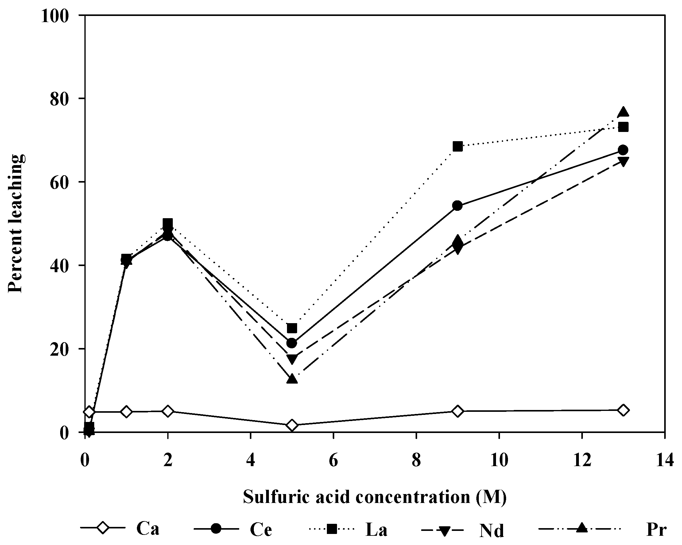
Figure 4 shows the change in the leaching efficiency with the sulfuric acid concentration. The experiments were run for 5 h at 20 °C. At low acid concentrations, the leaching level increased with increasing acid concentration. However, the leaching level decreased at 5.0 M. This may result from reprecipitation of REEs via calcium sulfate formation. It is known that calcium sulfate hydrates (gypsum, hemihydrate, and anhydrite) are readily formed wherever calcium and sulfate are present together in aqueous solutions [16].
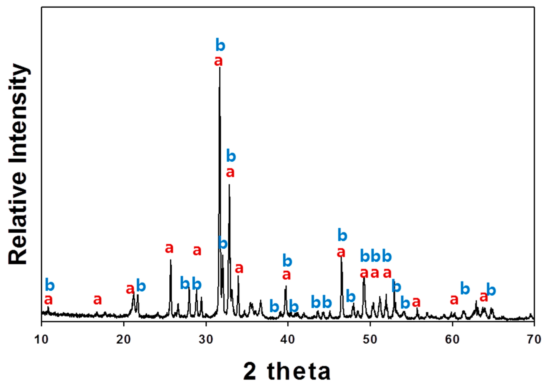
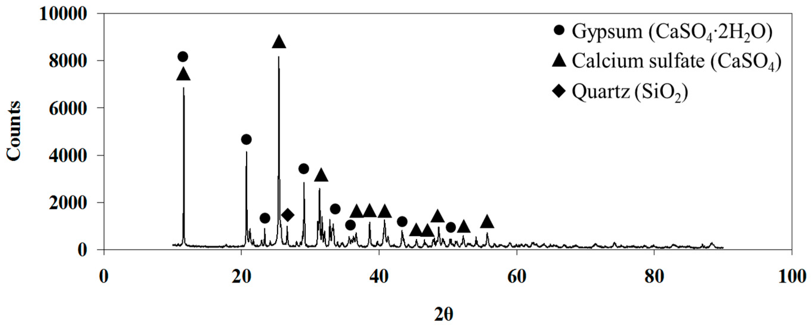
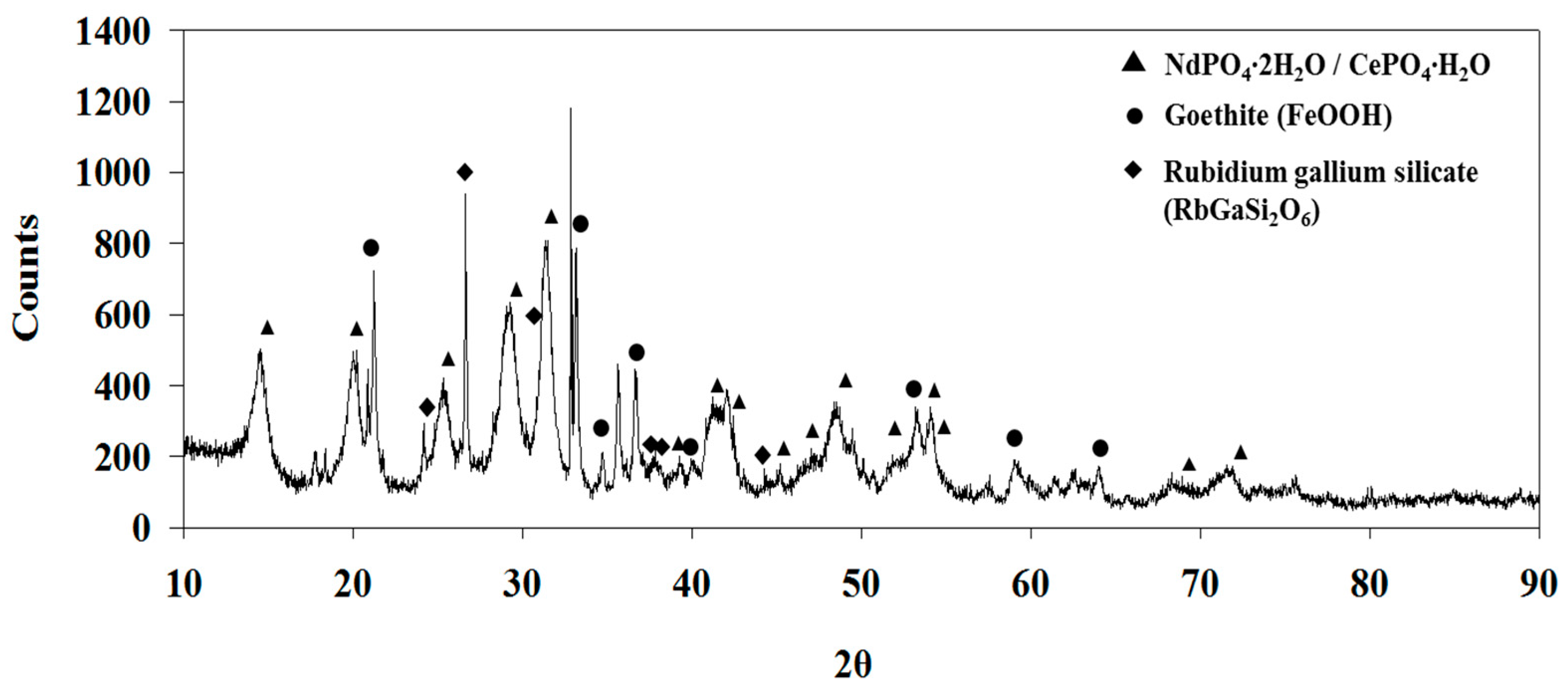
Indeed, the XRD analysis of the residue after leaching shows the presence of gypsum (CaSO4∙2H2O) and anhydrite (CaSO4) (Figure 5). This residue may contain REEs by isomorphous substitutions for Ca2+ [8,12,17,18], because Ca and REEs have similar ionic radii. To confirm the existence of REEs in the precipitated gypsum and CaSO4, the leaching residue was dried in atmosphere and was washed with water. The solution phase from this washing was found to contain a significant amount of Ca and REEs (1.03 g/L Ca, 0.08 g/L Ce, 0.03 g/L La, 0.03 g/L Nd, 0.02 g/L Pr, and 0.009 g/L Y), which indicates that the precipitated calcium sulfate hydrates contain REEs by ion substitution. The Ca concentration seems to be higher than the solubility of gypsum (2.4 g/L), but the solution may contain free calcium ions and associated calcium sulfate neutral species [CaSO4(aq)] dissolved from anhydrite [16,19].
On the other hand, when the concentration of sulfuric acid further increased above 5.0 M, the leaching level increased again. It can be postulated that the increase in the acidity may change the solution chemistry to limit the precipitation of calcium sulfate hydrates. To examine more closely the relationship between the leaching patterns and H2SO4 concentration, the Ca speciation was calculated for the Ca-SO4-H2O system using thermodynamic data available in the literature [20,21,22]:
HSO 4 + H 2 O = H 2 SO 4 + OH       K 1 = [ H 2 SO 4 ] [ OH ] [ HSO 4 ] = 3.002 × 10 26 ,
HSO 4 + OH = SO 4 2 + H 2 O       K 2 = [ SO 4 2 ] [ HSO 4 ] [ OH ] = 1.034 × 10 12 ,
Ca 2 + + OH = Ca ( OH ) +         K 3 = [ Ca ( OH ) + ] [ Ca 2 + ] [ OH ] = 25.119 ,
Ca 2 + + SO 4 2 = CaSO 4   ( aq )         K 4 = [ CaSO 4   ( aq ) ] [ Ca 2 + ] [ SO 4 2 ] = 1.157 × 10 2 ,
Ca 2 + + 2 OH = Ca ( OH ) 2         K s 1 = [ Ca 2 + ] [ OH ] 2 = 3.890 × 10 6 ,
Ca 2 + + SO 4 2 = CaSO 4   ( s )         K s 2 = [ Ca 2 + ] [ SO 4 2 ] = 4.930 × 10 5 ,
Ca 2 + + SO 4 2 + 2 H 2 O = CaSO 4 · 2 H 2 O     K s 3 = [ Ca 2 + ] [ SO 4 2 ] = 3.140 × 10 5 .
There are seven species in the solution: OH, H2SO4, HSO4, SO42−, Ca2+, Ca(OH)+, CaSO4(aq). Therefore, three more equations in addition to Equations (1)–(4) are required to calculate the equilibrium composition. Two additional equations used were mass balance equations for Ca species and sulfate species. One additional equation could be the charge balance equation, but in our calculations, the OH concentrations were assumed to be known and were calculated from the final pH of the solutions in the actual experiment. The total Ca concentration was assumed to be 0.5 M considering the number of moles of Ca in the ore. The equilibrium composition was then calculated under different levels of total sulfate concentrations (1.0, 2.0, 5.0, 9.8, and 13.0 M). If the calculated values were greater than any of the Ksp values [Equations (5)–(7)], the Ca2+ concentration was recalculated using the Equations (5)–(7) and the calculations were repeated until the calculated values satisfied all conditions. The exact solution was obtained by an iterative method using “Solver” function in MS Excel (Microsoft, Redmond, WA, USA).
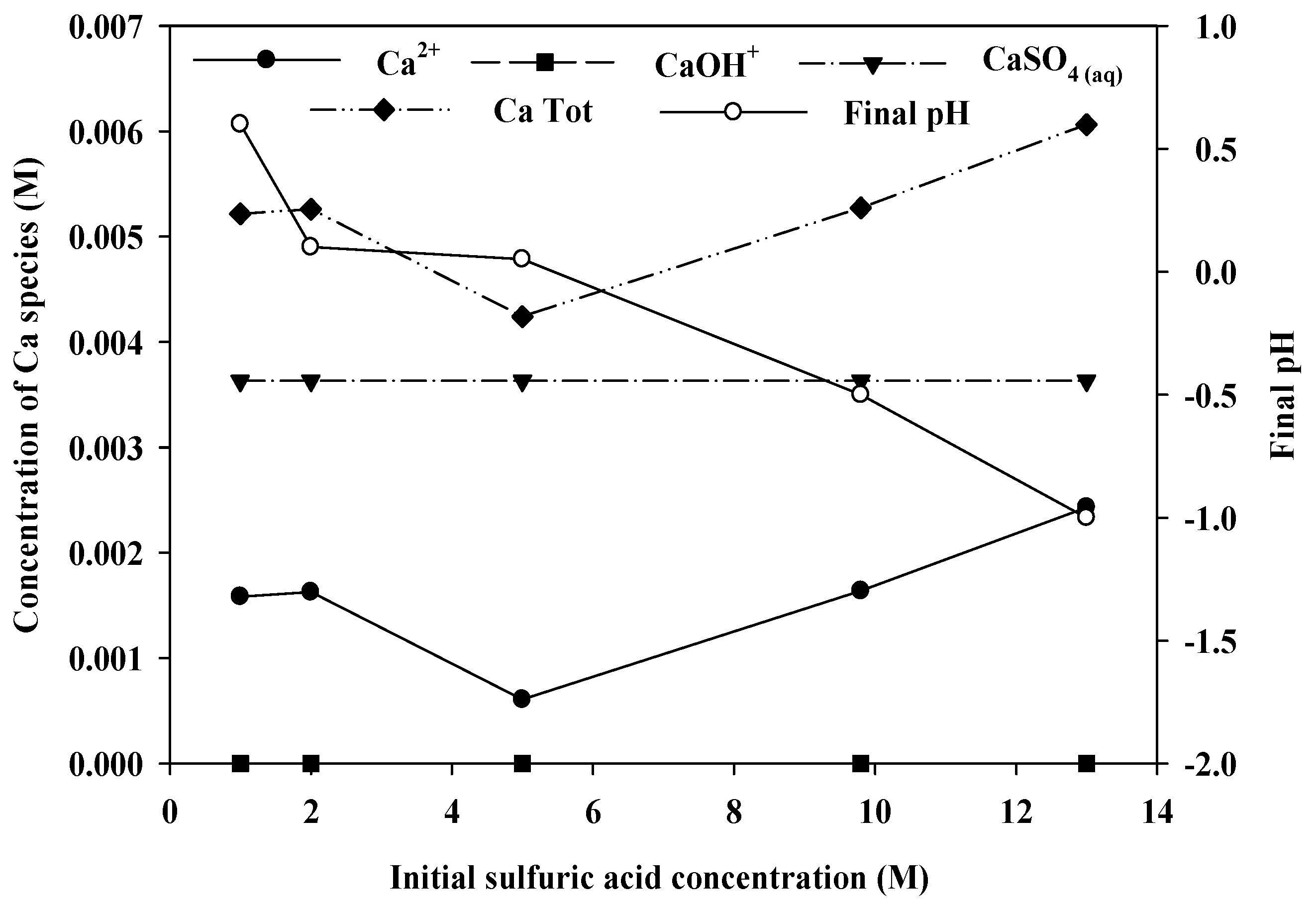
Figure 6 shows the calculation results, showing the distribution of Ca species as a function of the initial sulfuric acid concentration. In this highly acidic condition, Ca was present mainly in the form of Ca2+ and CaSO4(aq). The concentration of CaSO4(aq) does not change with the sulfuric acid concentration, as the solution become saturated owing to the high concentrations of Ca2+ and SO42−. On the other hand, the concentration of Ca2+ changes with the sulfuric acid concentration, showing a minimum at 5.0 M. The final pH of the solution decreased initially with increasing the sulfuric acid concentration, but remained the same from 2.0 to 5.0 M of sulfuric acid. However, with more addition of sulfuric acid, the final pH decreased again, which accompanies the increases in the concentration of Ca2+. It indicates that the concentration of Ca2+ species changed in a complicated manner due to the competing balance between the precipitation and dissolution of Ca, which is affected by H+, SO42 and Ca2+ in the solution. Accordingly, the total soluble Ca species varies with the sulfuric acid concentration in a pattern very similar to the leaching pattern. This result suggests that sulfuric acid may not be a good leaching agent for this ore, as the side reaction, Ca(REE) sulfate precipitation, limits the REE leaching level, which did not exceed 80%, even when a large excess of acid (13.0 M) was used.
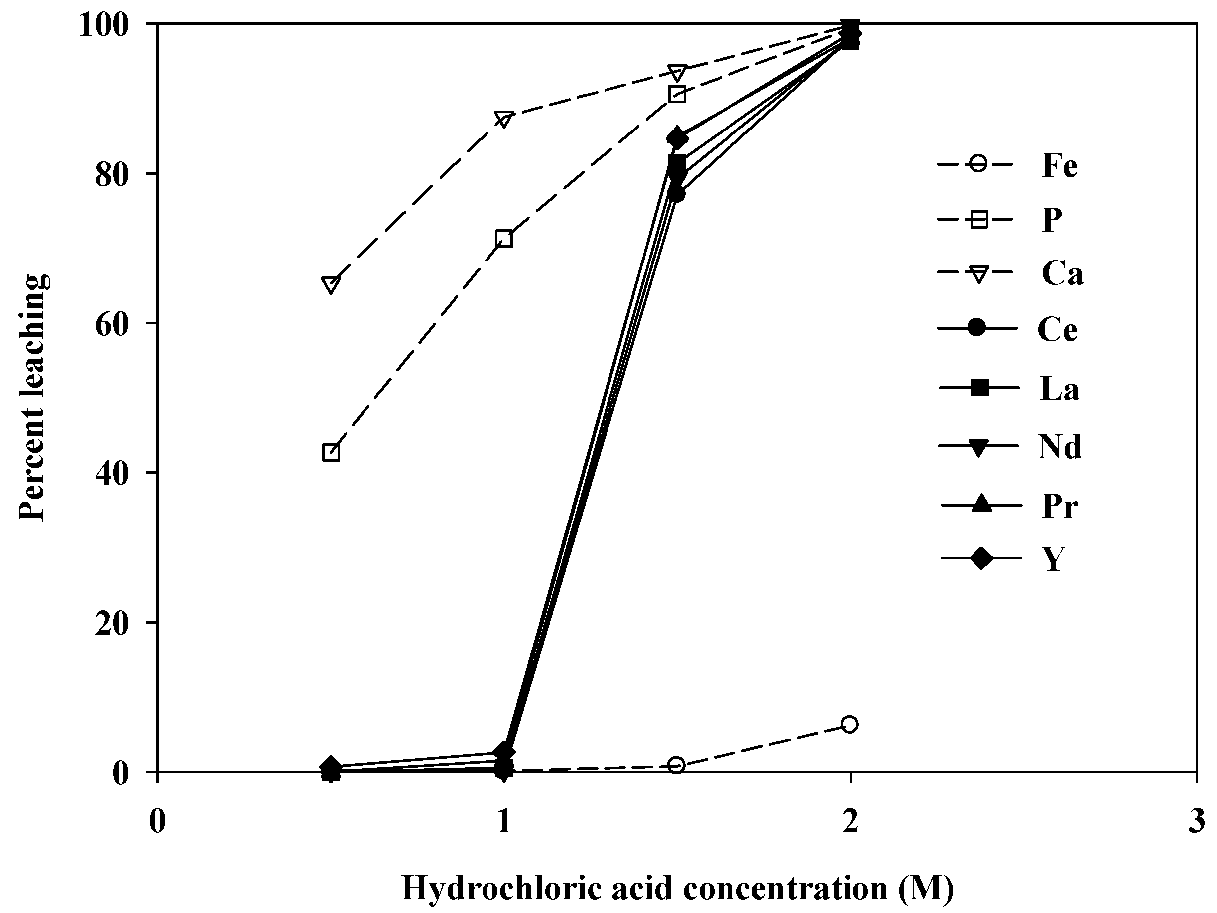
Figure 7 shows the variation in the leaching levels with the initial concentration of hydrochloric acid. Almost no REEs were leached when the concentration was less than 1.0 M. At higher concentrations of hydrochloric acid, the leaching levels increased sharply. At an acid concentration of 2.0 M, nearly 100% of the REEs were leached. However, the amount of Ca in the leachate was also very high (27,480 mg/L), which would undoubtedly cause complications during REE recovery by either precipitation or solvent extraction.
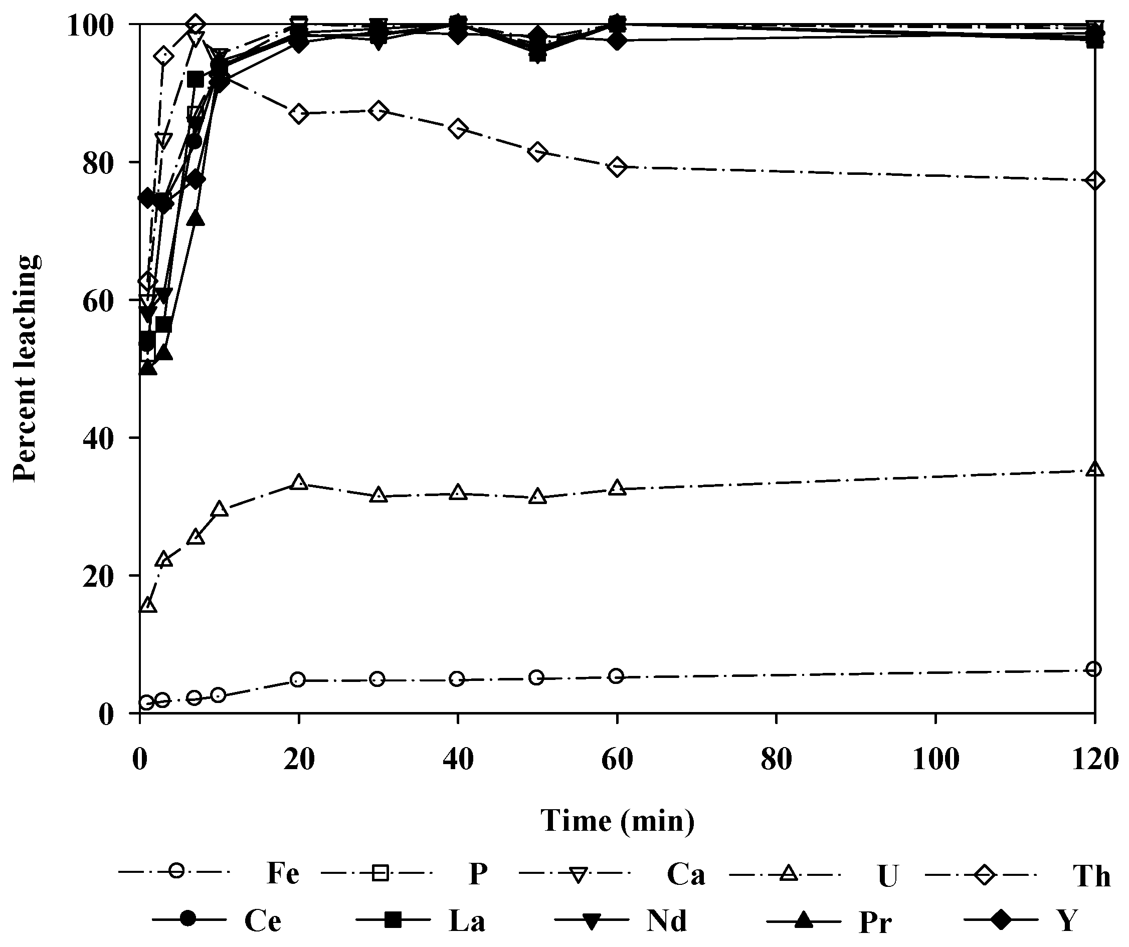
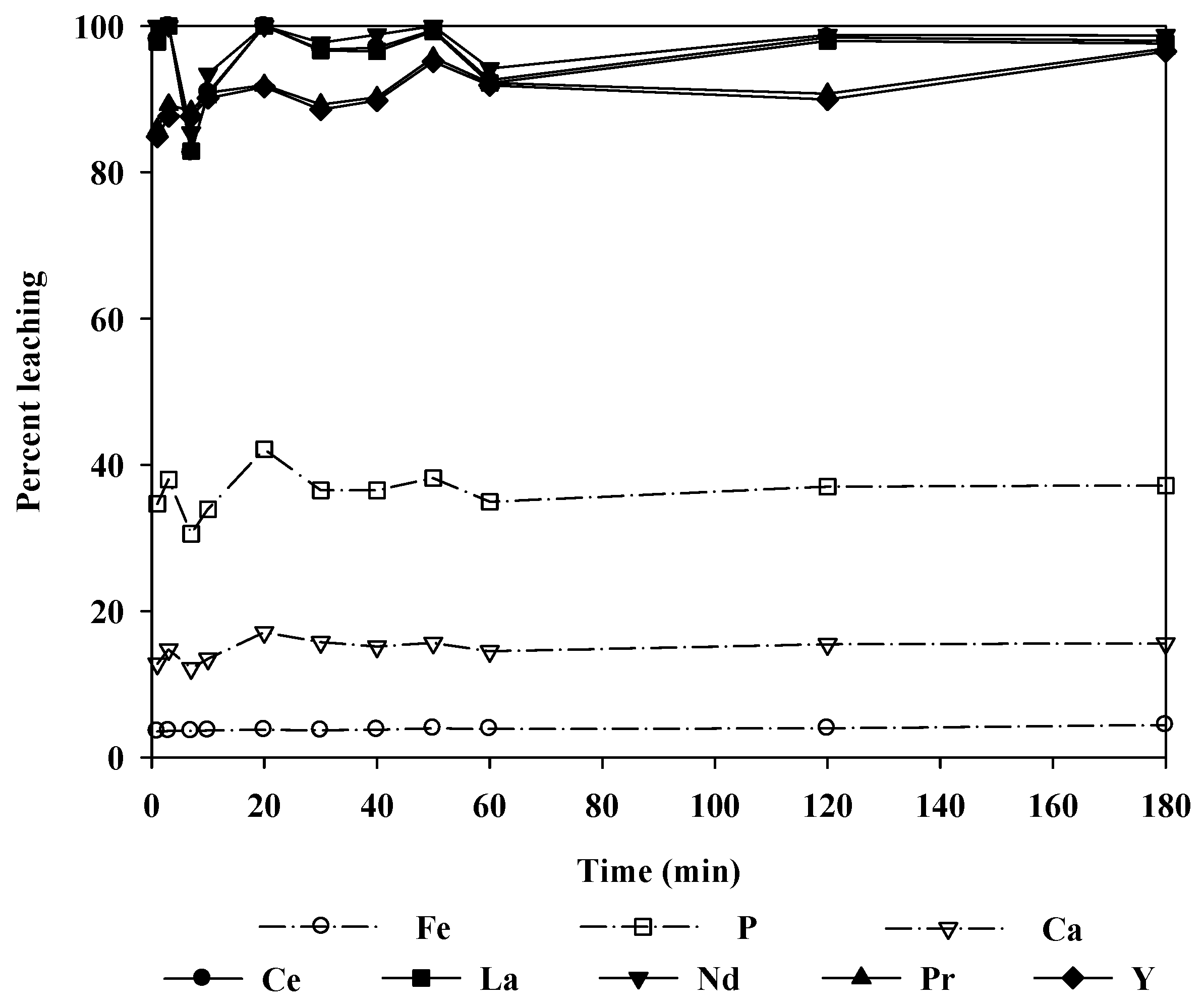
Figure 8 shows the change in the leaching levels with time when 2.0 M hydrochloric acid was used as the leaching agent. More than 90% of the REEs were leached in 10 min. At 1 h, almost 100% of the REEs were leached, and the reaction reached equilibrium in 2 h. It could be noted that the rate of the leaching reaction was quite fast. Thus, it was sufficient to leach the ore at room temperature for a relatively short time.
Unfortunately, the radioactive elements U and Th were also leached with the REEs, although the level of radioactivity was statistically insignificant for the ore treated in this study (U: 45 mg/L, Th: 24 mg/L). Additionally, the Th leaching level decreased with time because Th precipitated as phosphate in the relatively low pH region. Thus, the radioactivity of the leaching solution could be further decreased. Note, however, that if the radioactivity of the ore was significant, the removal of radioactive elements from the leachate would require the use of separation techniques such as selective precipitation or the solvent extraction method.
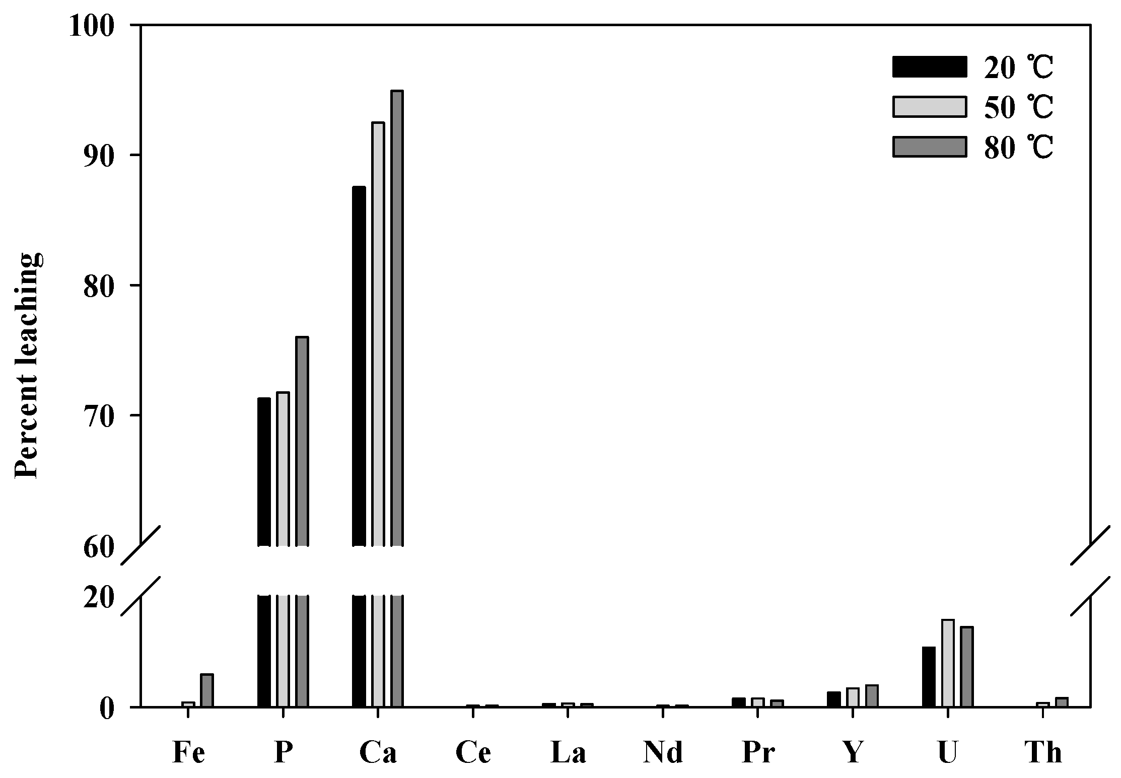
Leaching tests were conducted at elevated temperatures to determine whether the leaching levels and reaction rate could be improved. Because almost 100% of the REEs were leached using 2.0 M hydrochloric acid in an hour, tests of the temperature dependence were conducted using 1.0 M hydrochloric acid at 20, 50, and 80 °C. As shown in 
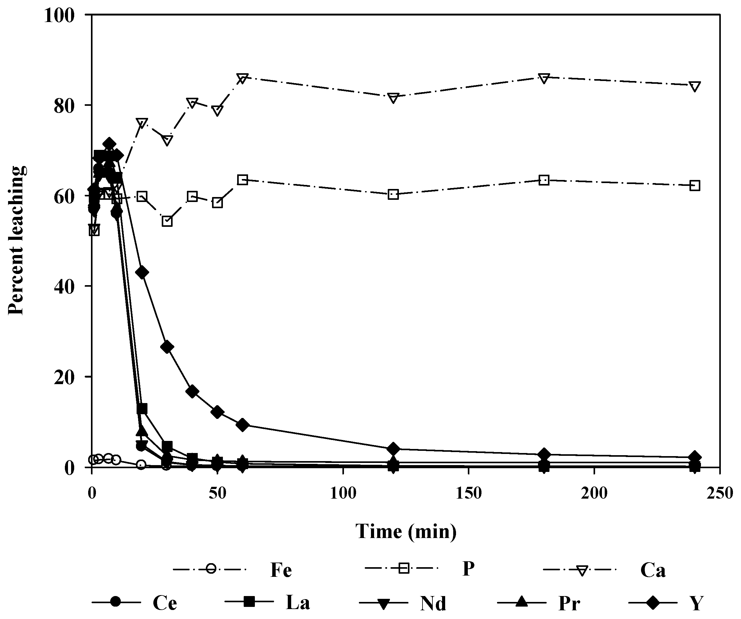
Figure 9, the overall leaching levels for all REEs did not increase significantly; however, other impurity ions (Fe, P, Ca, and U) were leached more as the temperature increased. Therefore, it is preferable to operate with a higher concentration of hydrochloric acid at room temperature than to operate at elevated temperatures.
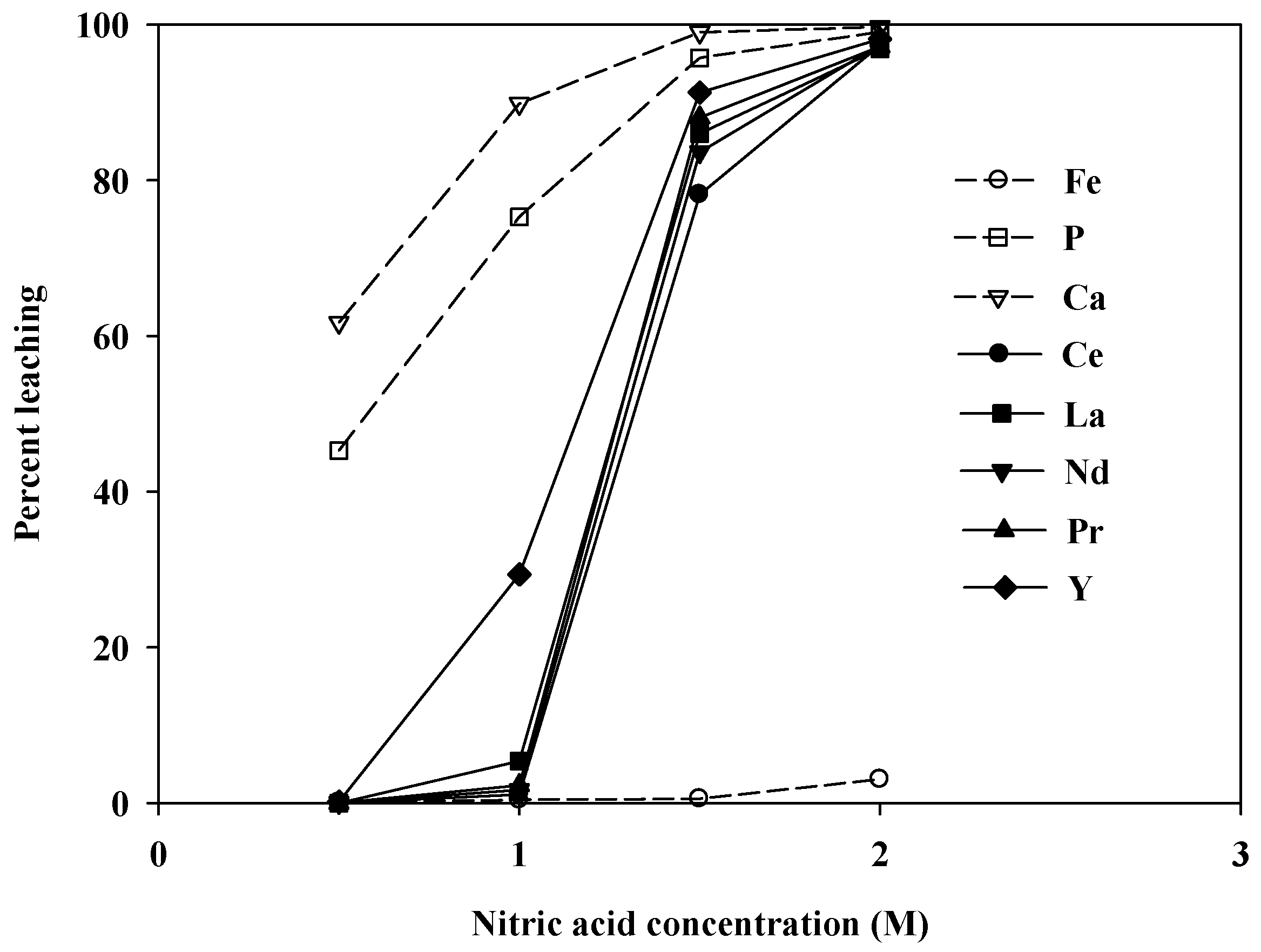
Figure 10 shows the leaching levels at varying concentrations of nitric acid. No REEs, aside from Y, were leached at 1.0 M, whereas impurities such as P and Ca were leached quite well. However, as the acid concentration was increased to 2.0 M, almost 100% of the REEs were leached. These results were similar to the hydrochloric acid case. Because nitric acid is generally more expensive than hydrochloric acid, it was not considered in later sections. Consequently, hydrochloric acid was chosen as the optimum leaching agent for this apatite REE ore, and the effects of other variables on the leaching efficiency were investigated using hydrochloric acid in later experiments.

3.3. Two-Stage Leaching

As mentioned previously, the leachate obtained using 2.0 M hydrochloric acid contained a significant amount of Ca, as the major mineral phase of the sample is apatite. Therefore, a two-stage leaching process was attempted to reduce the amount of Ca in the leachate.

3.3.1. Stage 1 Leaching

In stage 1, 1.0 M hydrochloric acid was used to dissolve the apatite. Figure 11 shows the change in the leaching levels of P and Ca ions together with the REEs over time. Within the first 10 min of leaching, the REE leaching levels were higher than those of P and Ca. This may result from the mineralogical structure of the ore. As mentioned earlier, the REE concentration was higher at the outer edge of the apatite grains than at the center. The monazite grains, which bore a much higher percentage of REEs, were also present at the surface of the apatite. Conversely, the amounts of P and Ca increase gradually from the edge to the center of the apatite grains. Thus, a high initial leaching level of REEs is expected, as the leaching solution reacts first with the outer layer of the solid particles. After 10 min, the REE levels in the leachate decreased. It seemed that this could be attributed to precipitation of REEs as phosphates.
To analyze the leaching behavior more specifically during stage 1, a thermodynamic analysis was performed to calculate the leaching pH values for apatite, REE phosphates, and Ca phosphate using thermodynamic data available in the literature [22,23,24,25,26,27]. It was assumed that the concentration of the substance reaches 1.0 mol/L for apatite and Ca phosphate, and 0.1 mol/L for REE phosphates. The leaching pH values were calculated on the basis of the chemical reactions given in Equations (8)–(10). The results are summarized in Table 3 and Table 4. Fluorapatite, hydroxyapatite, and chlorapatite leach at pH values of 1.0, 3.2, and 2.3, respectively. Therefore, in the early stages of leaching with 1.0 M hydrochloric acid, all three forms of apatite could be leached from the ore because the pH of the acid solution was 0:
Ca 10 ( PO 4 ) 6 X 2 + 20 H + = 10 Ca 2 + + 6 H 3 PO 4 + 2 HX   ( X = F , OH , Cl ) ,
Ca 3 ( PO 4 ) 2 + 6 H + = 3 Ca 2 + + 2 H 3 PO 4 ,
REEPO 4 + 3 H + = REE 3 + + H 3 PO 4 .
During leaching, it was found that the pH increased from 0 to approximately 1.5. In this range, the dissolved REEs and phosphate ions can react to form REE phosphates, as the leaching pH for REE phosphates is less than or around 0 (Table 4). In contrast, Ca does not precipitate because both apatite and Ca phosphate are still leachable in this pH region, as shown in Table 3. Therefore, Ca dissolution continues during this stage, whereas the amount of REEs in the liquid phase decreases as the REE phosphates precipitate.
In Figure 7 and Figure 11, it can be noted that the percentage of dissolved P is always less than that of Ca for 1.0 M hydrochloric acid. This also implies that the dissolved P is consumed as the REE phosphates form. Otherwise, the leaching levels of P, REEs, and Ca would be similar over time. Table 5 presents the hypothetical P leaching levels if no precipitation occurred. In these calculations, it was assumed that the REEs disappeared from the solution according to the reaction REE 3 + + PO 4 3 = REEPO 4 ; i.e., moles of phosphate ions and REEs were removed from the solution in a 1:1 ratio as precipitation progressed. When the number of moles of phosphate ions consumed by the precipitation reaction is calculated and added to the experimentally measured phosphate level, the calculated leaching levels of P are very close to those of Ca throughout the process. This confirms that the REE phosphates precipitate out of the solution during this stage.
Indeed, some REE phosphates were identified by XRD analysis of the residue from stage 1, as shown in Figure 12. This indicated that it would be possible to dissolve Ca and P selectively from the ore while keeping the REEs in the solid residue by using 1.0 M hydrochloric acid for a reasonable leaching time, approximately 3–4 h.

3.3.2. Stage 2 Leaching

The solid residue from stage 1 was subjected to stage 2 leaching using 2.0 M hydrochloric acid as a leaching agent. Figure 13 shows that the leaching of REEs reaches nearly 100% in a short time. Table 6 compares the leaching levels of REEs, calculated as the ratio of the amount of REEs in the leachate after 120 min of leaching to that in the raw sample, with those obtained by one-stage leaching under the same conditions. The amounts of the major impurities (Ca, P, and Fe) in the final leachate are also shown. The leaching levels of the REEs were not affected by the use of two-stage leaching, indicating that only the impurities were selectively leached during the first stage of leaching. As a consequence, the amounts of Ca and P in the final leachate were considerably reduced from 27,480 and 11,260 mg/L to 5030 and 4400 mg/L, respectively.

3.4. Optimal Processing Route

On the basis of the experimental results of this study, we propose a route for optimal processing and leaching of REEs from this ore, as shown in Figure 14. In this process, the ore is crushed and ground to 90% passing 0.3 mm. Then, magnetic separation is applied to separate Fe bearing minerals, which results in 60% removal of Fe with a 5%–6% loss of REEs. The Fe grade of the magnetic product is very high (over 70%), so it can be sold to the steel-making industry. The nonmagnetic stream is then subject to a two-stage leaching process. In stage 1, the ore is leached with 1.0 M HCl, where approximately 90% of the Ca is removed with no loss of REEs. The residue from stage 1 leaching is then subject to stage 2 leaching with 2.0 M HCl, where most of the REEs are leached out in an hour. The final recovery of REEs after leaching is around 92%–94% for each REE—a considerably higher amount than that yield by other current processing practices. Table 7 summarizes the metallurgical balance of the proposed processing flow.

4. Conclusions

The REE ore deposit currently under investigation can become a new major source of REEs judging from its magnitude and grade. Furthermore, test results show that this ore can be processed by a rather simple route with a recovery of all REEs of over 90% REEs. It seems that physical separation of REE-containing minerals may not be easy. However, removal of Fe-bearing minerals before leaching is possible using magnetic separation with minimal loss of REEs. This would reduce the operation cost of the leaching process because much of the acid could be consumed by Fe minerals in the ore. At the same time, additional profit can be realized by the sale of Fe concentrate as the magnetic product has a smelter grade.
Leaching tests reveal that REEs can be effectively extracted using HCl at ambient temperature and pressure. The U and Th content of the leachate was not at a significant level that demands additional treatment. However, the Ca level was very high when direct leaching with HCl was performed. Consequently, a two-stage leaching process was developed. In stage 1, leaching is conducted under a mild condition (1.0 M HCl) to elute Ca from the ore. In stage 2 leaching, 90%–100% of the REEs were recovered using 2.0 M HCl. The final recovery of REEs after leaching is very high around 92%–94% for each REE—a considerably higher amount than that yield by other current processing practices.

Acknowledgments

This work was supported by a grant from the Korea Institute of Energy Technology Evaluation and Planning (KETEP) funded by the Ministry of Trade, Industry, and Energy (MOTIE) of the Korean government (No. 20122010300041).

Author Contributions

Rina Kim performed the experiments, and analyzed and interpreted the data. Heechan Cho was the Principal Investigator of this work and edited the paper. Kenneth N. Han contributed to interpretation of the data. Kihong Kim and Myoungwook Mun performed magnetic separation tests and helped to analyze the data.

Conflicts of Interest

The authors declare no conflict of interest.

References

  1. Daly, J.C.K. Mongolia’s rare earth reserves draw foreign investor interest. Centr. Asia-Caucasus Anal. 2011, 13, 6–8. [Google Scholar]
  2. Altangerel, T. Rare Earth Deposits in Mongolia. Available online: http://criticalmetalsmeeting.com/download/CM-2013_Finalized_program.pdf (accessed on 30 June 2016).
  3. Sanematsu, K.; Kon, Y.; Hirando, H.; Watanabe, Y. Mineralogy and Geochemistry of the Mushgai Kudag REE Deposit, Mongolia. In Geological Society of America Abstracts with Programs; The Geological Society of America: Denver, CO, USA, 2010; Volume 42, p. 335. [Google Scholar]
  4. Chi, R.; Tian, J.; Zhu, G.; Wu, Y.; Li, S.; Wang, C.; Zhou, Z.A. Kinetics of rare earth leaching from a mangnese-removed weathered rare-earth mud in hydrochloric acid solutions. Separ. Sci. Technol. 2006, 41, 1099–1113. [Google Scholar] [CrossRef]
  5. Zielinski, S.; Szczepanik, A.; Buca, M. Recovery of lanthanides from Kola Apatite in phosphoric acid manufacture. J. Chem. Technol. Biotechnol. 1993, 56, 355–360. [Google Scholar] [CrossRef]
  6. Jones, A.P.; Wall, F.; Williams, C.T. Rare Earth Minerals—Chemistry, Origin and Ore Deposits; Chapman & Hall: London, UK, 1996. [Google Scholar]
  7. Martin, P.; Carlot, G.; Chevarier, A.; Den-Auwer, C.; Panczer, G. Mechanisms involved in thermal diffusion of rare earth elements in apatite. J. Nucl. Mater. 1999, 275, 268–276. [Google Scholar] [CrossRef]
  8. Jorjani, E.; Bagherieh, A.H.; Chelgani, S.C. Rare earth elements leaching from Chadormalu apatite concentrate: Laboratory studies and regression predictions. Korean J. Chem. Eng. 2011, 28, 557–562. [Google Scholar] [CrossRef]
  9. Aly, M.M.; Mohammed, N.A. Recovery of lanthanides from Abu Tartur Phosphate Rock, Egypt. Hydrometallurgy 1999, 52, 199–206. [Google Scholar] [CrossRef]
  10. Sandström, Å.; Fredriksson, A. Apatite for extraction—Leaching of Kiirunavaara Apatite for simultaneous production of fertilizers and REE. In Proceedings of the 26th International Mineral Processing Congress, IMPC 2012: Innovative Processing for Sustainable Growth, New Delhi, India, 24–28 September 2012; pp. 4707–4714.
  11. Pereira, F.; Bilal, E. Phosphoric acid extraction and rare earth recovery from apatites of the Brazilian Phosphatic Ores. Romanian J. Mineral. Depos. 2012, 85, 49–52. [Google Scholar]
  12. Habashi, F. The recovery of the lanthanides from Phosphate Rock. J. Chem. Technol. Biotechnol. Chem. Technol. 1985, 35, 5–14. [Google Scholar] [CrossRef]
  13. Garamjav, D.; Jargalan, S. Introduction to REE metallogeny of the Mongolia. Mong. Geosci. 2009, 35, 73–76. [Google Scholar]
  14. Enkhbayar, D.; Seo, J.; Choi, S.; Lee, Y.; Batmunkh, E. Mineral chemistry of REE-rich apatite and sulfur-rich monazite from the Mushgai Khudag, Alkaline Volcanic-Plutonic Complex, South Mongolia. Int. J. Geosci. 2016, 7, 20–31. [Google Scholar] [CrossRef]
  15. Peelman, S.; Sun, Z.H.I.; Sietsma, J.; Yang, Y. Hydrometallurgical extraction of rare earth elements from low grade mine tailings. In Rare Metal Technology 2016; Alan, S., Kim, H., Neelameggham, N.R., Ouchi, T., Oosterhof, H., Eds.; John Wiley & Sons, Inc.: Hoboken, NJ, USA, 2016. [Google Scholar]
  16. Azimi, G.; Papangelakis, V.G. The Solubility of gypsum and anhydrite in simulated laterite pressure acid leach solutions up to 250 °C. Hydrometallurgy 2010, 102, 1–13. [Google Scholar] [CrossRef]
  17. Todorovsky, D.S.; Milanova, M.M.; Minkova, N.L.; Balarev, C. Solubility of some lanthanide sulfate in polycomponent systems containing H2SO4. Monatsh. Chem. 1993, 124, 673–679. [Google Scholar] [CrossRef]
  18. Wang, L.; Long, Z.; Huang, X.; Yu, Y.; Cui, D.; Zhang, G. Recovery of rare earths from wet-process phosphoric acid. Hydrometallurgy 2010, 101, 41–47. [Google Scholar] [CrossRef]
  19. Gangolli, S. The Dictionary of Substances and Their Effects: C; Royal Society of Chemistry: London, UK, 1999. [Google Scholar]
  20. Martell, E.A.; Smith, R.M. Critical Stability Constants Volume 4; Plenum Press: New York, NY, USA, 1982. [Google Scholar]
  21. Lide, D.R. CRC Handbook of Chemistry and Physics, 83rd ed.; CRC Press: Cleveland, OH, USA, 2002. [Google Scholar]
  22. Kim, E.; Osseo-Asare, K. Aqueous stability of Thorium and rare earth metals in monazite hydrometallurgy: Eh-pH diagrams for the systems Th-, Ce-, La-, Nd- (PO4)-(SO4)-H2O at 25 °C. Hydrometallurgy 2012, 113–114, 67–78. [Google Scholar] [CrossRef]
  23. Firsching, F.H.; Brune, S.N. Solubility products of the trivalent rare-earth phosphates. J. Chem. Eng. Data 1991, 36, 93–95. [Google Scholar] [CrossRef]
  24. Oxtoby, D.W.; Gillis, H.P.; Nachtrieb, N.H. Principles of Modern Chemistry, 5th ed.; Thomson: Pacific Grove, CA, USA, 2002. [Google Scholar]
  25. La Iglesia, A. Estimating the thermodynamic properties of phosphate minerals at high and low temperature from the sum of constituent units. Estud. Geol. 2009, 65, 109–119. [Google Scholar] [CrossRef]
  26. Han, K.N.; Kellar, J.J.; Cross, W.M.; Safarzadeh, S. Opportunities and challenges for treating rare-earth elements. Geosyst. Eng. 2014, 17, 178–194. [Google Scholar] [CrossRef]
  27. Kim, R.; Cho, H.C.; Han, K.N. Behavior of anions in association with metal ions under hydrometallurgical environments Part I—OH effect on various cations. Miner. Metall. Proc. 2014, 31, 40–47. [Google Scholar]
Figure 1. X-ray diffraction (XRD) analysis of the sample. (a) (Ce, La, Nd) hydroxyapatite, fluorapatite, chlorapatite; (b) Nd, Mn silicates.
Minerals 06 00063 g001
Figure 2. The layered structure of apatite in the sample [14].
Minerals 06 00063 g002
Figure 3. Cumulative size distribution of the sample after crushing and milling.
Minerals 06 00063 g003
Figure 4. Leaching levels at various initial sulfuric acid concentrations at 20 °C.
Minerals 06 00063 g004
Figure 5. XRD analysis of residue from leaching with 13.0 M sulfuric acid.
Minerals 06 00063 g005
Figure 6. Ca speciation under different initial sulfuric acid concentrations at 25 °C, 1 atm. Equilibrium composition calculated by solving Equations (1)–(7).
Minerals 06 00063 g006
Figure 7. Leaching levels at various initial hydrochloric acid concentrations at 20 °C. Leaching time: 2 h; solid/liquid (S/L) ratio (w/v): 1:9.
Minerals 06 00063 g007
Figure 8. Change in leaching levels with time using hydrochloric acid at 20 °C. Initial acid concentration: 2.0 M; leaching time: 2 h; S/L ratio: 1:9.
Minerals 06 00063 g008
Figure 9. Comparison of final leaching levels using hydrochloric acid at 20, 50 and 80 °C. Initial acid concentration: 1.0 M; leaching time: 3 h; S/L ratio: 1:9.
Minerals 06 00063 g009
Figure 10. Leaching levels at various initial nitric acid concentrations at 20 °C. Leaching time: 2 h; S/L ratio: 1:9.
Minerals 06 00063 g010
Figure 11. Change in leaching levels over the course of stage 1 using hydrochloric acid at 20 °C. Initial acid concentration: 1.0 M; leaching time: 4 h; S/L ratio: 1:9.
Minerals 06 00063 g011
Figure 12. XRD analysis of the residue from stage 1, showing the presence of REE phosphates.
Minerals 06 00063 g012
Figure 13. Leaching levels for various elements over the course of stage 2 using hydrochloric acid. Initial acid concentration: 2.0 M; leaching time: 3 h; S/L ratio: 1:9.
Minerals 06 00063 g013
Figure 14. Optimal processing of the ore.
Minerals 06 00063 g014
Table 1. X-ray fluorescence (XRF) analysis of the sample.
FormulaConcentration (%)FormulaConcentration (%)
CaO32.75MgO0.53
Fe2O322.91SrO0.47
P2O518.30Na2O0.45
SiO29.65Pr6O110.42
CeO25.80MnO0.29
La2O33.01Y2O30.28
SO31.80K2O0.25
Nd2O31.48ThO20.06
Al2O30.87ZnO0.05
TiO20.62CuO0.04
Table 2. Result of XRF analysis of raw sample and magnetically separated samples.
Magnetic IntensitySampleYield (%)Content (wt %)
Fe2O3CeO2La2O3Nd2O3Pr6O11Y2O3
-Raw10022.95.83.01.50.40.3
0.2 TMagnetic19.572.51.50.90.40.10.1
Nonmagnetic80.510.66.83.61.60.50.3
Recovery to Nonmagnetic (%)37.695.094.594.996.796.1
Table 3. Thermodynamic data and leaching pH of apatite and calcium phosphate according to Equations (8) and (9), respectively (ΔG°f of H+: 0 kJ/mol; Ca2+: −553.58 kJ/mol; H3PO4: −1142.54 kJ/mol).
ApatiteΔG°f(kJ/mol)Leaching pH
ApatiteHX1ΔG°rxn
Ca10(PO4)6F2 Fluorapatite–12,885.9–296.82–98.761.00
Ca10(PO4)6(OH)2 Hydroxyapatite–12,503.5–237.18–361.933.24
Ca10(PO4)6Cl2 Chlorapatite–12,403.0–131.23–250.502.33
Ca3(PO4)2–3884.82-–61.001.84
1 X = F, OH, Cl for fluor, hydroxy and chlorapatite, respectively.
Table 4. Thermodynamic data and leaching pH of REE phosphates according to Equation (10) (ΔG°f of H+: 0 kJ/mol; H3PO4: −1142.54 kJ/mol).
REE PhosphateΔGf° (kJ/mol)Leaching pH
REEPO4REE3+ΔG°rxn
YPO4–1846.96−686.9217.50–0.36
LaPO4–1898.43–730.4625.43–0.82
CePO4–1827.32–677.337.450.23
PrPO4–1880.33–712.8824.92–0.79
NdPO4–1870.92–704.0924.29–0.75
Table 5. Comparison of P and Ca leaching level during stage 1 leaching.
Leach Time (min)P Leaching LevelCa Leaching Level
ActualRe-Calculated
152.2552.2652.93
360.2660.2860.86
760.2960.3161.01
1059.2960.2362.07
2059.8374.5376.31
3054.3369.3072.41
4059.8376.8780.74
5058.4475.2079.01
6063.5081.8386.16
12060.2477.7081.80
18063.4281.8386.16
24062.2180.2584.37
Table 6. Comparison of REE leaching levels in the leachate after 120 min and the amount of some impurities in the final leachate between one and two-stage processes.
Type of LeachingREE Leach Level (%)Amount of Impurity (mg/L)
CeLaNdPrYCaPFe
One-stage98.197.798.098.098.727,48011,260190
Two-stage98.497.998.890.790.050304400147
Table 7. Metallurgical balance of the optimal process.
ProcessSample Yield (Wt %)Elements (%)Distribution (%)
CaFeCeLaNdPrYCaFeCeLaNdPrY
Magnetic separationMagnetic19.518.0872.521.480.870.360.070.055.0462.375.045.495.093.303.89
Nonmagnetic80.4936.9310.616.763.641.650.530.3294.9637.6394.9694.5194.9196.7096.11
1st stage leachingLeachate46.0654.440.020.010.010.000.010.0180.120.050.060.160.061.002.11
Residue34.4213.5024.7815.808.513.851.220.7314.8437.5994.9094.3594.8595.7094.00
2nd stage leachingLeachate17.1427.012.2031.1116.707.642.401.4514.791.6693.0592.2493.7093.7192.76
Residue17.280.0947.180.620.380.090.050.020.0535.921.852.101.151.991.24
Calculated feed100.031.3022.695.733.101.400.440.27100.00100.00100.00100.00100.00100.00100.00
Measured feed100.032.7522.915.803.011.480.420.28-------

