Carbothermic Reduction of Ore-Coal Composite Pellets in a Tall Pellets Bed

School of Metallurgy, Northeastern University, Shenyang 110819, China
*
Authors to whom correspondence should be addressed.
Minerals 2018, 8(12), 550; https://doi.org/10.3390/min8120550
Submission received: 19 October 2018
/
Revised: 14 November 2018
/
Accepted: 21 November 2018
/
Published: 27 November 2018
(This article belongs to the Special Issue Towards Sustainability in Extractive Metallurgy)
Abstract
:Recently, increasing attention has been paid to alternative ironmaking processes due to the desire for sustainable development. Aiming to develop a new direct reduction technology, the paired straight hearth (PSH) furnace process, the carbothermic reduction of ore-coal composite pellets in a tall pellets bed was investigated at the lab-scale in the present work. The experimental results show that, under the present experimental conditions, when the height of the pellets bed is 80 mm (16–18 mm each layer, and 5 layers), the optimal amount of carbon to add is C/O = 0.95. Addition of either more or less carbon does not benefit the production of high quality direct reduced iron (DRI). The longer reduction time (60 min) may result in more molten slag in the top layer of DRI, which does not benefit the actual operation. At 50 min, the metallization degree could be up to 85.24%. When the experiment was performed using 5 layers of pellets (about 80 mm in height) and at 50 min duration, the productivity of metallic iron could reach 55.41 kg-MFe/m2·h (or 75.26 kg-DRI/m2·h). Therefore, compared with a traditional shallow bed (one or two layers), the metallization degree and productivity of DRI can be effectively increased in a tall pellets bed. It should be pointed out that the pellets bed and the temperature should be increased simultaneously. The present investigation may give some guidance for the commercial development of the PSH process in the future.
1. Introduction
In the coming decades, the blast furnace (BF) will be the dominant ironmaking reactor in the world. However, there have been continuing efforts all over the world to search for alternative ironmaking processes because of high capital investment, coke requirements, and environmental concerns associated with the preparatory steps of the raw materials for the BF, e.g., coke making and sintering. Many alternative ironmaking processes have been developed over the past decades. Chemically self-reducing green balls (ore-coal composite pellets) contain carbonaceous reductant, and only heat is needed to convert green balls to direct reduced iron (DRI). A hearth-type furnace is the proper choice for these ore-coal composite pellets to commercially produce DRI.
There are some studies regarding the reduction of ore-coal composite pellets [1,2,3,4,5,6,7,8,9,10,11,12,13,14,15]. Kasai et al. carried out some reduction experiments in a combustion bed packed with the composite pellets. They found that re-oxidation could be significantly suppressed by admixing CaO-bearing material or coating it around the composites [1]. Murakami et al. evaluated the effect of pressure on the gasification and reduction of the composites, and found that the gasification temperature decreased and the weight loss fraction at the target temperature increased with an increase in pressure [2,3,4]. Yunus et al. investigated the reduction of low grade iron ore deposits mixed with oil palm empty fruit bunch (EFB) as a substitution for coke. Then, they found that EFB char appeared to be a promising energy source for decreasing coal consumption in ironmaking, and reducing CO2 emissions [5]. Takyu et al. have fundamentally examined the reduction by volatile matter in a coal-hematite ore composite. They found that the reduction degree of hematite ore initially increased with increasing content of volatile matter in coal, and that control of the heating rate is a possible way to promote reduction at a low temperature [6].
Based on the above literatures, previous studies have mainly focused on reduction parameters for ore-coal composite pellets, including flux (CaO-bearing material), pressure, additive fuel (EFB), volatile matter, and others. These studies have obtained much valuable and meaningful information on the carbothermic reduction of ore-coal composites. However, the height of the pellets bed was seldom considered, because they were focused on the characteristics and fundamental mechanism of the reaction between the ore and reductant. Therefore, in previous studies, usually a shallow pellets bed (1–2 layers, 20–25 mm) and lower temperatures (1000–1300 °C) were used to reduce ore-coal composite pellets. However, the lower metallization degree and lower productivity are inevitable disadvantages due to the contradictory requirements of fuel in the oxidation compartment and the reduction compartment (Figure 1). In order to increase the energy efficiency of fuel, the ratio of CO/CO2 should be lower, but it is easy to re-oxidize the newly formed DRI, which results in a lower metallization degree. On the other hand, in order to avoid DRI from re-oxidation, a high ratio of CO/CO2 is necessary, but the energy efficiency of fuel and the flame temperature are lower. As a consequence, the radiation heat transfer, which is proportional to T4 of the heat source, will be lower and result in a lower metallization degree too. Therefore, a lower metallization degree and lower productivity are inevitable for a shallow bed [16].
Based on the reduction of ore-coal composite pellets in a furnace hearth, and aiming to solve the problem of the contradictory requirements of fuel in the oxidation compartment and the reduction compartment, Wei-Kao Lu of McMaster University in Canada proposed a new direct reduction process, which is named the paired straight hearth (PSH) furnace process [17]. Similar to shallow pellets beds, the PSH process may also be divided into an oxidation compartment and a reduction compartment (Figure 2). The PSH process has two operational characteristics: (1) a tall pellets bed (5–7 layers, 80–120 mm) in the reduction compartment; and (2) a high temperature (1500–1550 °C) in the oxidation compartment, which is caused by the full combustion of CO to CO2.
There are two key points in the development of the PSH process: (1) In the tall pellets bed, the newly formed DRI at the top of the bed can be protected from re-oxidation by the upward gas flow (which is CO rich) generated during the reduction in the tall pellets bed, and enhanced by the high volatile coal in the green ball over a longer period of the reduction time; (2) Efficient heat transfer from the “oxidation compartment” (where heat is generated) to the “reduction compartment” (where heat is consumed by the endothermic reaction and sensible heat of substances). Therefore, the PSH was considered as a possible process to produce DRI with a high quality, low carbon rate, and consequentially low CO2 emissions.
However, since the PSH process was proposed by Lu, the reaction characteristics of the carbothermic reduction of ore-coal composite pellets in tall pellets beds have not been better understood. Therefore, the present work was done. The aims of this study are as follows: (1) common raw materials were used to better understand the common reaction characteristics of the carbothermic reduction of ore-coal composite pellets in tall pellets beds, which have not been found in the literature so far; (2) the effects of some basic operation parameters on the carbothermic reduction were experimentally investigated, including the amount of carbon addition (denoted as C/O) and the reduction time; (3) comparison on the productivity of metallic iron among different pellets layers (different height in pellets bed); and (4) give some suggestions for choosing reasonable operation parameters in future commercial development of the PSH process.
2. Experimental
2.1. Raw Materials
The chemical composition of the iron ore concentrate used in this work is shown in Table 1. It should be noted that the moisture is 7.22% in the original concentrate. The chemical analysis was carried out under dry conditions (7.22% of H2O was dried), including TFe (Total Fe), FeO, SiO2, CaO, MgO, Al2O3, and LOI (Loss of Ignition). In the dried concentrate, a slight increase in LOI (−1.45) is caused by the oxidation of magnetite. In order to better understand the minerals in the iron ore, X-ray diffraction (XRD, X’ Pert Pro; PANalyical, Almelo, The Netherlands) analysis was conducted, and the pattern is shown in Figure 3. Based on the chemical analysis and X-ray diffract, the iron ore was found to be primarily magnetite, and the main gangue is SiO2. The iron ore concentrate was ground by shatter-box, and 100% ore passed −0.074 mm for pelletizing.
The proximate analysis and ash analysis of the pulverized coal is shown in Table 2. The volatile matter (VM) in the coal is about 26%. For the preparation of ore-coal composite pellets, coal is also ground, and 100% passed −0.221 mm for pelletizing.
2.2. Experimental Set-Up
In the present work, the carbothermic reduction experiments of ore-coal composite pellets in tall pellets beds were carried out in an electric muffle furnace. The experimental procedure consisted of the following steps, and the temperature profile of the furnace is shown in Figure 4.
- Mixing of raw materials. Effective mixing of ore and coal is an essential step to ensure proper homogeneous reaction throughout the pellets. Therefore, first the ore and coal were mixed in an intensive mixer to ensure the uniform mixing of ore and coal, and a homogeneous reaction in the ore-coal composite pellets.
- Pelletizing. The diameter of the ore-coal composite pellet is about 16–18 mm. The total H2O content in the wet green ball is about 8.5–9.0%. In order to avoid the crack of pellets in the high temperature furnace due to evaporation, the wet green balls should be dried before charging into the furnace.
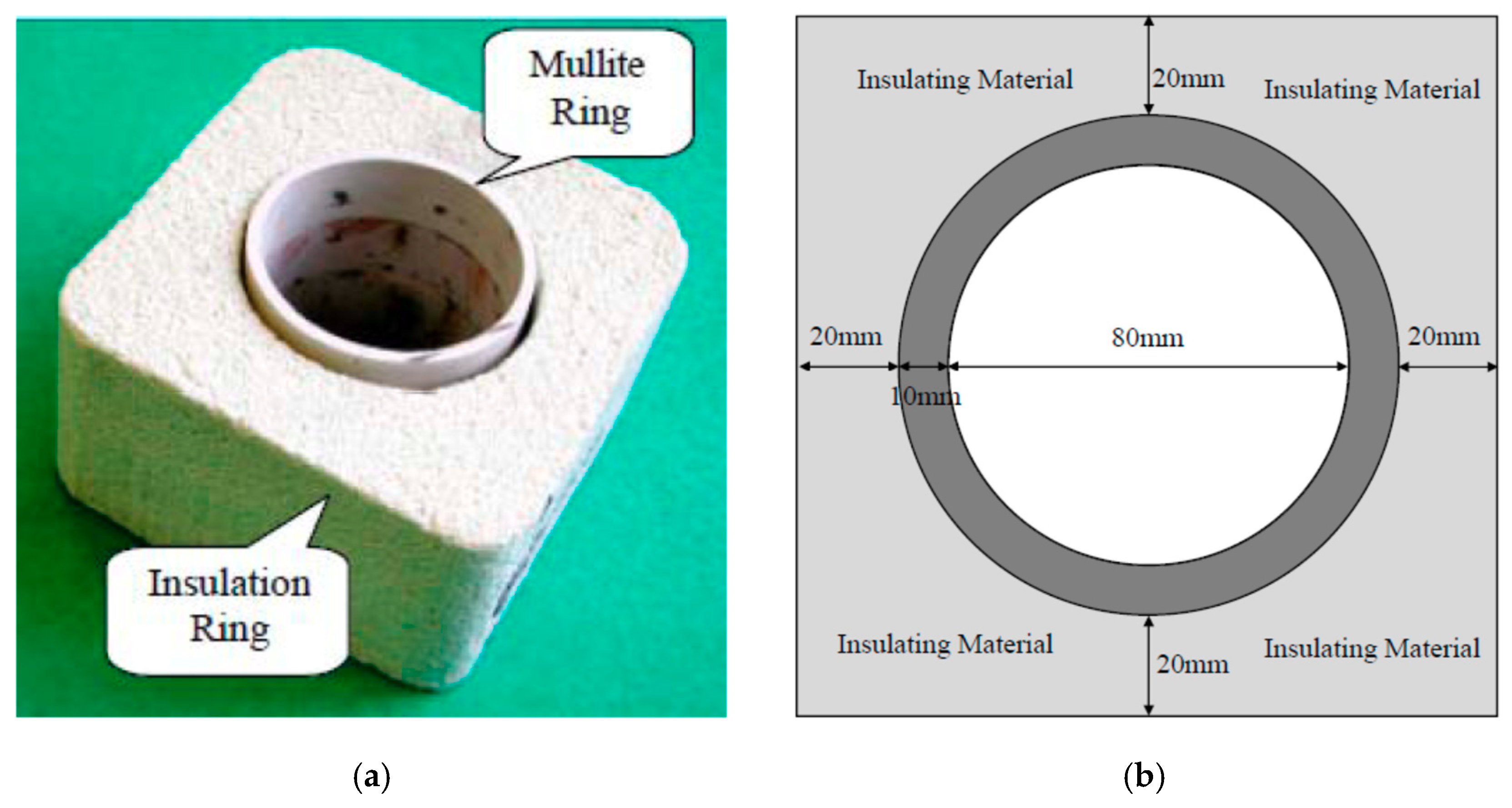
- A special crucible was made for holding composite pellets in muffle furnace (Figure 5). The crucible consists of two parts: (a) the mullite ring (the inner diameter is 80 mm) to retain the upward gas in a vertical direction in the pellets bed; and (b) the insulating materials surrounding the mullite ring to obstruct the heat transfer from the horizontal direction of the pellets bed.
- The special crucible was put into the furnace. Then, the temperature of the furnace was heated to 1200 °C in air atmosphere, and the crucible was pre-heated to 1200 °C in the furnace.
- The furnace door was opened, and 500 g of the dried composite pellets was charged into the crucible. The height of pellets bed is about 80 mm (5 layers, and 12–13 pellets each layer), and the void ratio of packing bed is about 14–18%.
- The furnace temperature was kept at 1200 °C for 5 min. Then, it was heated to 1500 °C in about 20 min (15 °C/min), and kept at 1500 °C until the target time.
- When the target reduction time was reached, the entire crucible was taken out of the furnace, and the surrounding insulating materials were immediately taken away from the crucible to stop the reduction reaction. Then, the hot DRI bed is quenched in liquid N2 to prevent the DRI from re-oxidation.
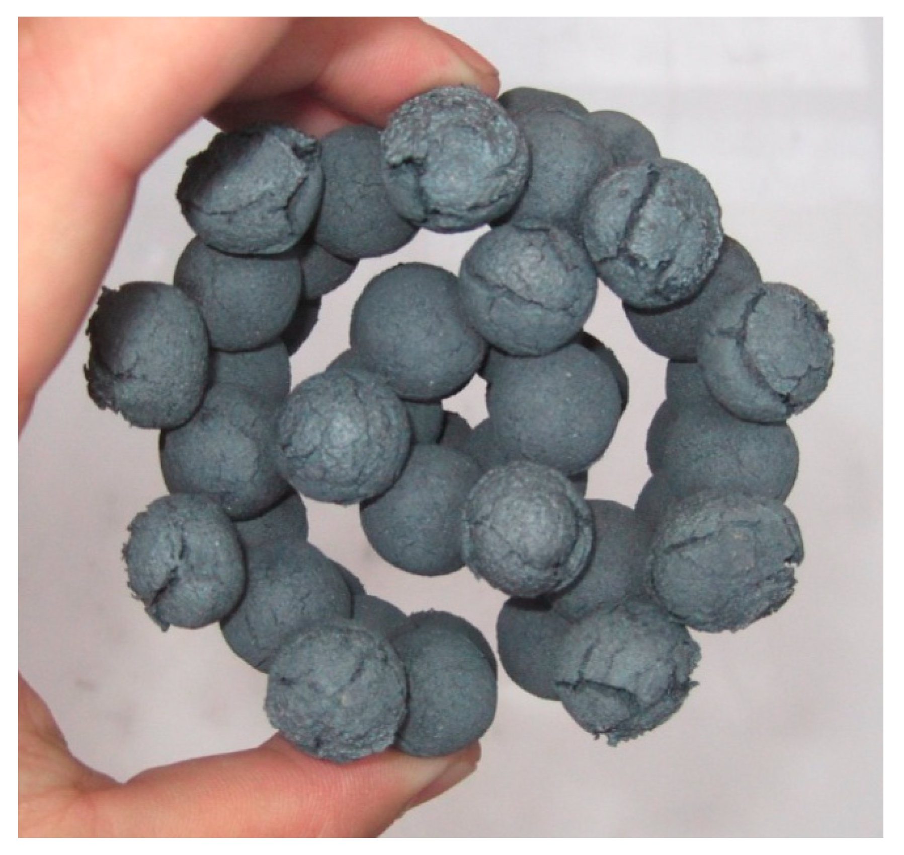
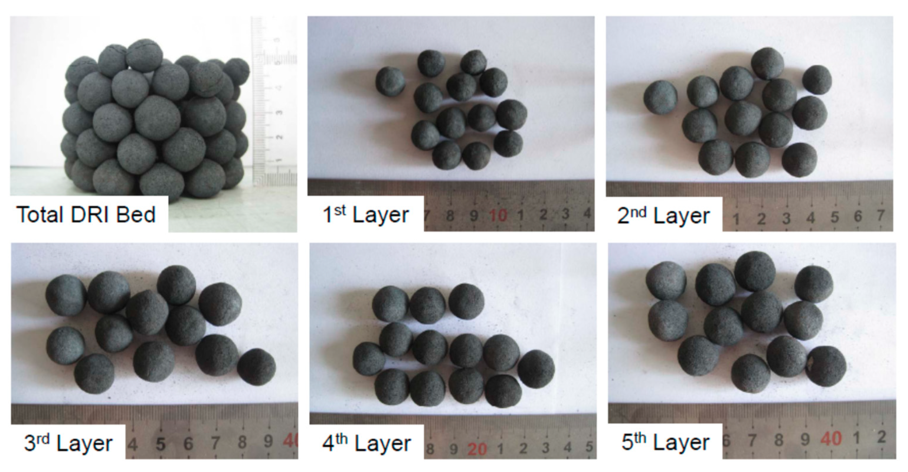
- Divide the DRI bed. The cooled DRI bed is shown in Figure 6. From top to bottom, the first 12–13 pellets are defined as the 1st layer, then the second 12–13 pellets are defined as the 2nd layer, then the 3rd layer, 4th layer, and 12–13 pellets on the bottom are defined as the 5th layer. Finally, the total DRI bed is divided into 5 layers from top to bottom.
- Eight pellets in each layer were randomly selected for chemical analysis. Total Fe (TFe) and Metallic Fe (MFe) were obtained. Then, for each layer, the ratio of metallic Fe to total Fe was defined as metallization degree (MD = MFe/TFe), which was an actual value (not average value). The metallization degrees (MD) of the total DRI bed, which is an actual value too, can be calculated by the following equation:MD (total bed) = [MFe (1st layer) × Weight (1st layer) + MFe (2nd layer) × Weight (2nd layer) + … + MFe (5th layer) × Weight (5th layer)]/[TFe (1st layer) × Weight (1st layer) + TFe (2nd layer) × Weight (2nd layer) + … + TFe (5th layer) × Weight (5th layer)]
3. Experimental Results and Analysis
3.1. Effects of Amount of Carbon Addition (C/O)
3.1.1. Metallization Degree
The definition of the amount of carbon addition is the gram-atomic ratio of the fixed carbon in coal to the combined oxygen in iron oxides, denoted as C/O (molar ratio). In this work, C/O = 0.80, 0.95 and 1.10. The reduction time is 50min in this section.
The metallization degrees (MD) of DRI specimens with different C/O are shown in Figure 7. It can be seen: (1) where C/O = 0.80, the MD is relatively low (about 78% for the total 5 layers of DRI) because the reductant is not sufficient; (2) where C/O = 0.95 and C/O = 1.10, the MD is obviously increased to about 85% and 86%, which indicates that the reductant in these pellets is sufficient; (3) it is inevitable that part of the DRI is re-oxidized in the top layer, so the MD first increases from the 1st layer to the 3rd layer. Then the MD decreases from the 3rd layer to the 4th layer, because radiative heat transfer is difficult in a higher pellets bed; (4) the MD of the DRI in the 5th layer (bottom layer) is higher than the 4th layer. The reason for this is that the pellets in the 5th layer can be heated from the hot bottom of the crucible by the heat pre-stored in the refractory.
3.1.2. Metallographic Analysis
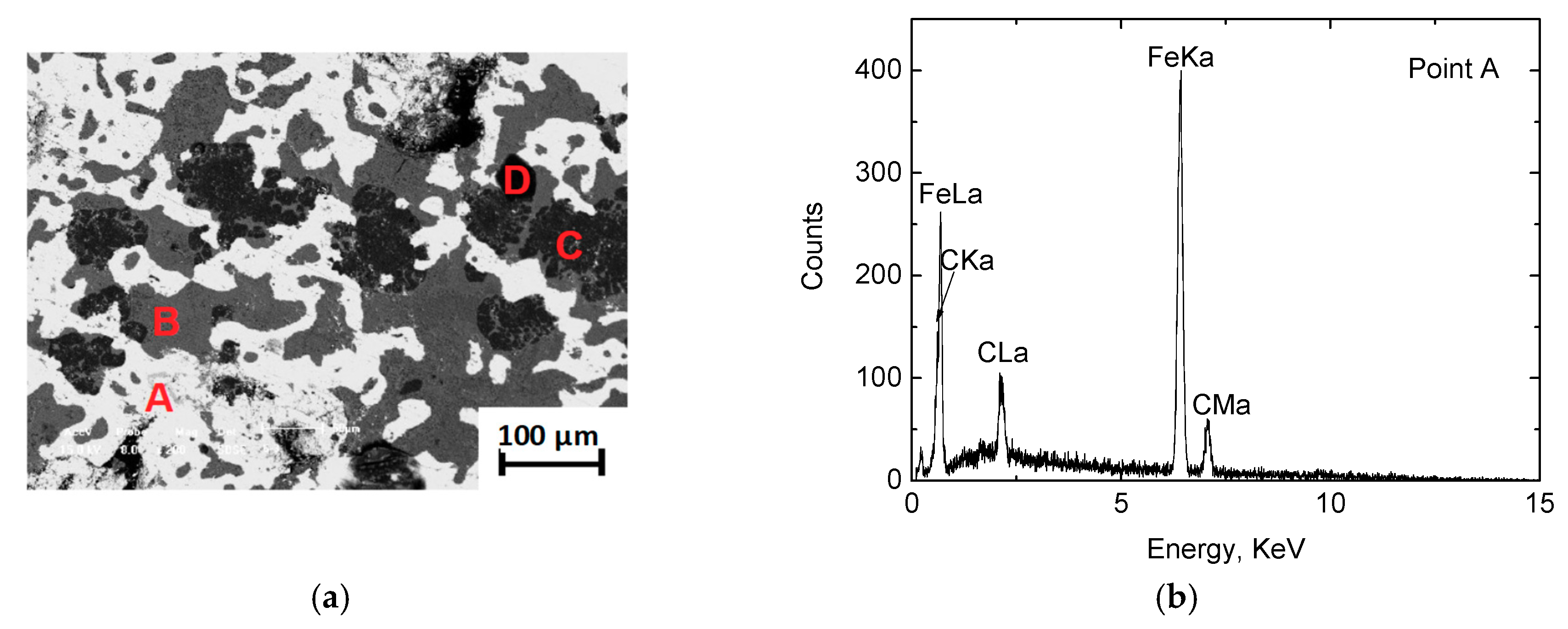
A typical metallographic picture and energy disperse spectroscopy (SEM-EDS, Ultra Plus; Carl Zeiss GmbH, Jena, Germany) of the DRI specimen is shown in Figure 8. It can be concluded that there are mainly three phases: (1) the white zone, as presented by point A, is the metallic iron phase; (2) the light grey zone, as presented by point B, consists mainly of fayalite (2FeO·SiO2) and the slag phase of silicon oxide, iron oxide, and aluminum oxide, with the former being crystallized from molten slag on cooling. It should be noted that the DRI in the 2nd layer is better protected from re-oxidation than the 1st layer, which results in less liquid slag and fayalite. Therefore, the slag phase is homogeneous; (3) the deep grey zone, as presented by point C, is quartz. In addition, the black zone, as presented by point D, is the area of pores inside the pellets. Both in the metallic phase and the slag phase, there is the element carbon, because carburization is inevitable in ore-coal composite pellets.
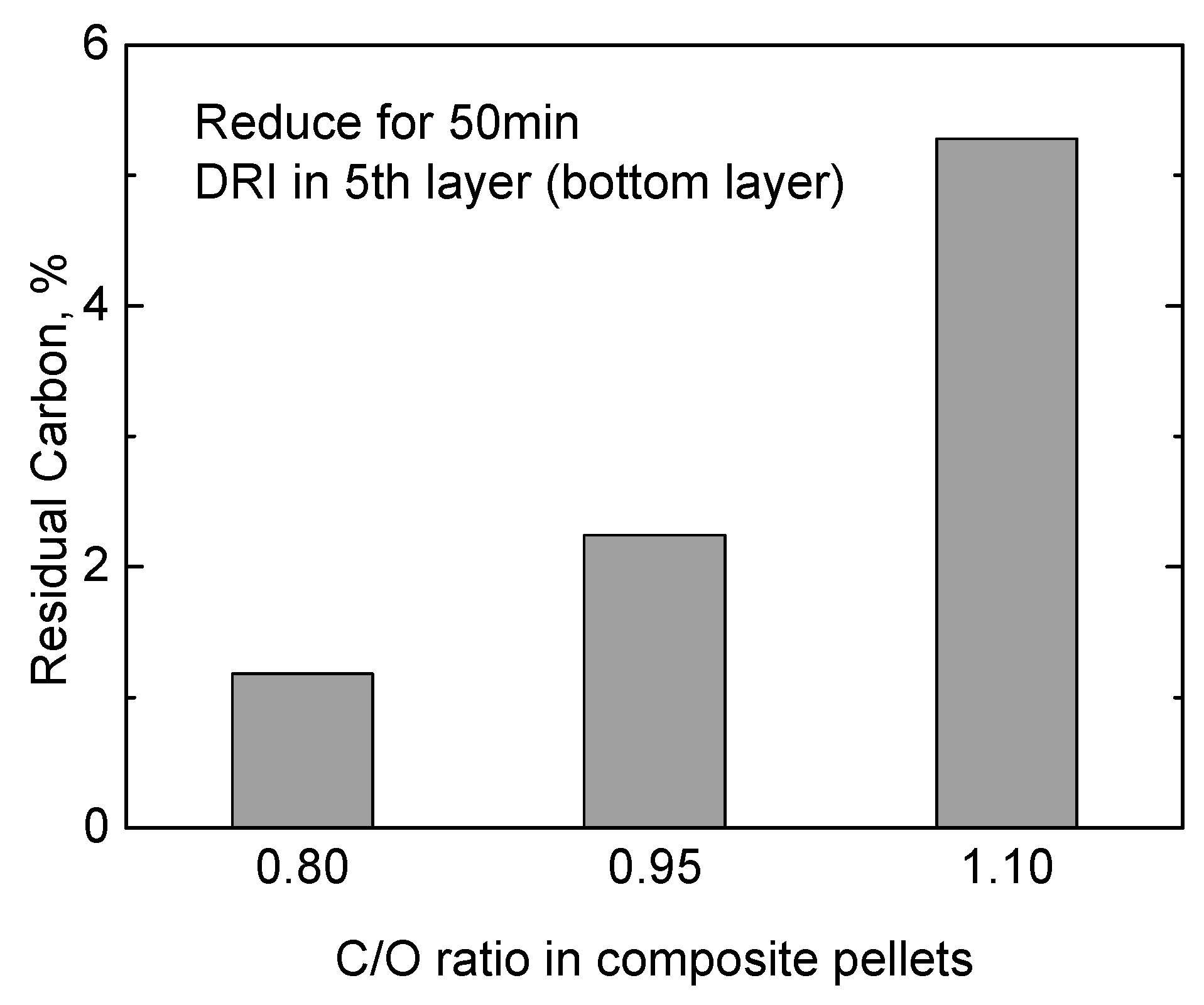
Other than the typical metallographic picture shown in Figure 8, in the metallographic picture of the 5th layer DRI of C/O = 1.1 (Figure 9), there is some black and loose powder. SEM-EDS is used to analyze the element in this powder area. Based on Figure 9, it can be seen that there is some carbon (solid C in coal) and silica (ash in coal). This proves that the coal addition (C/O) is excessive, and some residual carbon remains in the DRI, which does not benefit the actual DRI production. Therefore, in order to better understand the exact carbon content in DRI, a quantitative chemical analysis was used for the residual carbon in the 5th layer (bottom layer) DRI with different C/O, and the result is shown in Figure 10.
As shown in Figure 7, the metallization degrees of the total DRI bed are similar in cases of C/O = 0.95 and C/O = 1.10 (the difference may be within error). But the residual carbon of C/O = 1.10 is much more than C/O = 0.95 in Figure 10. Therefore, C/O = 0.95 is considered to be the optimal amount of carbon addition in the next stage of experiments.
3.2. Carbothermic Reduction for 50 min and 60 min
Based on the preliminary experiments, for 5 layers of pellets, the reduction time should be 50 min at least. So in this section, the reduction time of 50 min and 60 min were investigated, and experimental results are shown in Figure 11. From the figure, it can be seen that: (1) with a reduction time of 60 min, the MD in the 4th and 5th layers is higher than for 50min, but the MD in the 1st layer is lower than for 50 min; (2) the MD of the total DRI bed for 50 min and 60 min are 85.24% and 86.03%, respectively.
The metallographic picture and energy spectrum of the 1st layer DRI specimen for 60 min is shown in Figure 12. The white zone is metallic iron. The deep grey phase (presented by point A) is quartz, which is still a zone of un-melting solid grains due to its high melting point. The light grey phase (presented by point B) and the middle grey phase (presented by point C) are molten slag (mainly fayalite, 2FeO·SiO2). It can be interpreted that in the later stage of reduction, the up-ward protective gas evolved less and less, so a little bit of newly formed metallic iron was re-oxidized to FeO. Then, the oxides of silicon, aluminum and some iron formed molten slag. On cooling, fayalite crystallized from the molten slag and distributed in the final amorphous slag phase after solidification. The banding structure then formed. The formation of more molten slag does not benefit the actual operation. Therefore, 50 min is considered to be the optimal reduction time for an 80 mm bed (5 layers) in the present work, because the MD had no real change at all between 50 min and 60 min.
3.3. Productivity of the Tall Pellets Bed
In traditional work, kg-DRI/m2·h is used to evaluate the productivity of DRI. But this unit ignores the quality of DRI (metallization degree). In the present work, kg-MFe/m2·h is used as the unit to evaluate the productivity of metallic iron. For this unit, both the quality of DRI (metallization degree) and quantity of DRI (productivity) are considered simultaneously. The productivity presented by kg-MFe/m2·h, which is an actual value (not average value), may be calculated by the following equation:
Productivity = [MFe (1st layer) × Weight (1st layer) + MFe (2nd layer) × Weight (2nd layer) + … + MFe (5th layer) × Weight (5th layer)]/[Acreage (m2) × Time (h)]
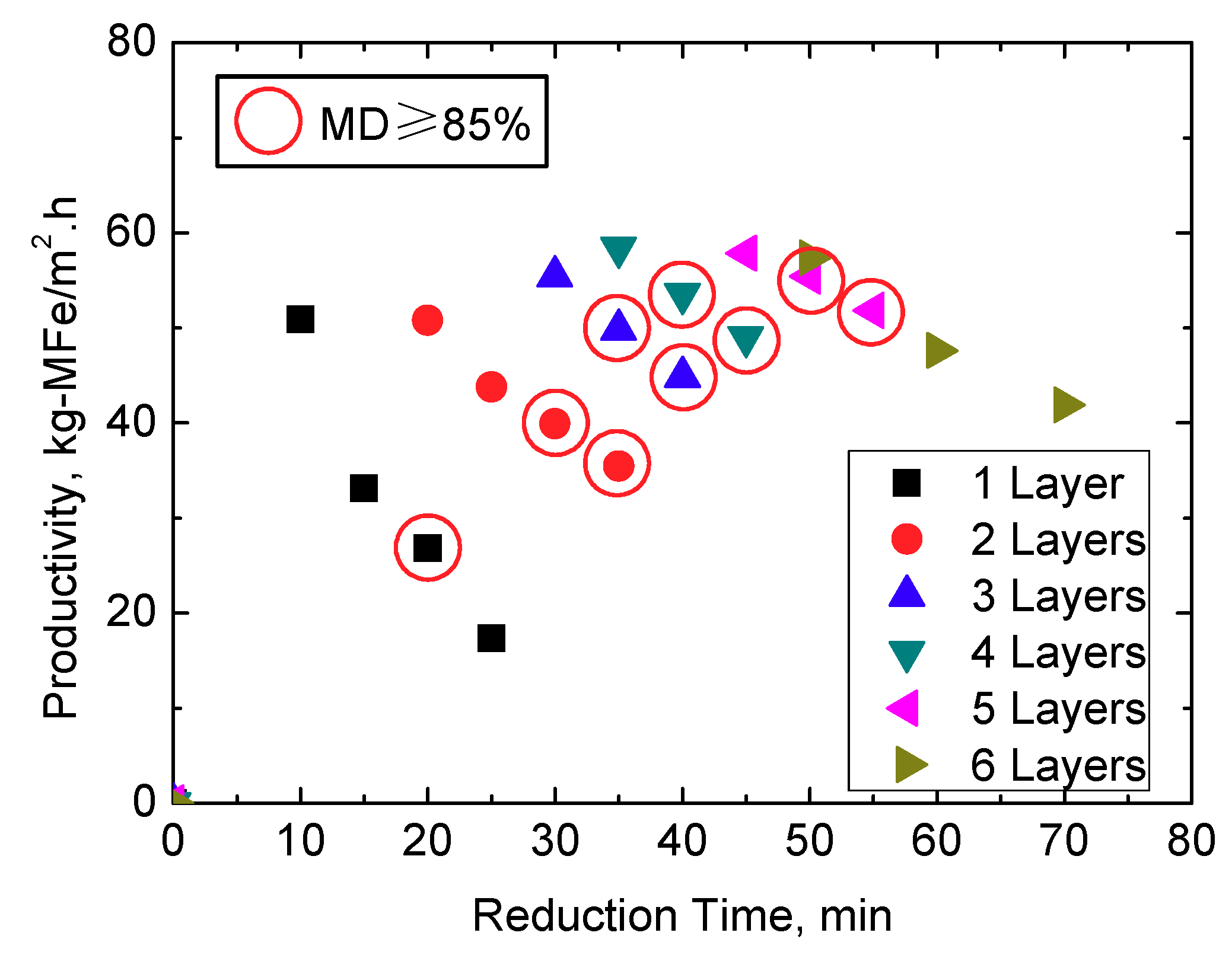
In this series of experiments, a 5 min variant is adopted. The effects of pellets layers and reduction time on the productivity of metallic iron are shown in Figure 13. It is worthy to note that a shorter reduction time does not necessarily generate higher productivity, because it may result in an MD that is too low to satisfy the requirement of ironmaking production. Therefore, a productivity with MD ≥ 85% is selected and circled by a ring in this figure. It can be seen, for certain layers, there are one or two points which can meet an MD ≥ 85%. For example, in the case of the four-layers pellets bed, the MD of DRI reduced for 40 min and 45 min are about 87% and 89%, respectively. Both of them can meet with an MD ≥ 85%. Between them, the productivity of 40 min is higher than 45 min. So, the productivity of 40 min (the maximum productivity for the four-layers bed) is selected in Figure 14.
Similar, the maximum productivities for other different layers beds are selected in Figure 14 too. It should be noted that the minimum requirement of 85% of MD is not reached by extending the reduction time to 70 min in the case of 6 layers. So, in Figure 14, there is no data on 6 layers. From the figure, one can conclude that the productivity denoted by kg-MFe/m2 (with different layers and different reduction times) increases with the increase of the height of the pellets bed. In lab-scale experiments, under the condition of 5 layers (about 80 mm) and 50 min, the productivity of metallic iron can reach 55.41 kg-MFe/m2·h (or 75.26 kg-DRI/m2·h). Therefore, tall pellets beds (and simultaneously high temperatures) can increase the productivity of DRI. The reason for this is that more layers of pellets are simultaneously heated, and the reduction reaction occurs in different layers at the same time. So the productivity of DRI can be significantly increased in the PSH process (tall pellets bed) compared with the traditional shallow bed (one or two layers).
4. Discussion
4.1. Optimal Parameters
4.1.1. Carbon Addition
Generally, C/O should be adjusted to meet the minimum requirement of the reduction of ore-coal composite pellets. Addition of either more or less carbon does not benefit the production of high quality DRI, including a high metallization degree, high density and strength etc., and these are the reaction characteristics of carbothermic reduction in a tall pellets bed. If more excessive residual carbon remains in the DRI, there are the following disadvantages: (1) grade of total iron decreases; (2) ash content increases with increasing coal addition, which weakens the density and strength of the DRI, which in turn is not good for storage and long-distance transportation; (3) a carbonaceous resource is wasted. Therefore, C/O = 0.95 is considered as the optimal amount of carbon addition in the present work.
4.1.2. Reduction Time
The longer reduction time (60 min in Section 3.2) may result in the following three problems: (1) more melting and corrosive slag formed; (2) it does not benefit the effective utilization of thermal energy, because the MD of the DRI does not obviously increase; (3) one of the characteristics of the PSH process is high productivity. A longer reduction time does not increase productivity. There are two reasons why 40, 30, and other shorter times cannot be optimal: lower metallization degree and lower productivity. (1) In Figure 13, where there are 5 layers (pink points), the MD is less than 85% when the reduction time is 45min. If the reduction time is shorter than 45min, the MD will be lower. (2) A lower MD means less metallic iron is produced, and this results in lower productivity of metallic iron. Therefore, 50 min is considered to be the optimal reduction time for an 80 mm bed (5 layers) in the present work.
4.2. Heat Transfer
As mentioned above, there are two key points for the carbothermic reduction in a tall pellets bed: (1) prevention for newly formed DRI from re-oxidation; and (2) efficient heat transfer from top to bottom in the pellets bed. Based on above experiments, the newly formed DRI can be protected from re-oxidation by the upward CO-rich gas flow generated during the reduction in the tall pellets bed, and the total MD of the DRI bed can be up to 85%. So, the effective protection from re-oxidation is the basis for the high temperature and high heat transfer, because the radiation heat transfer is proportional to T4 of the heat source. From the viewpoint of the process control, the radiation heat transfer from heating source to the bottom of the bed is the critical step of the process. In the above experiments, the newly formed DRI in the top layer will shrink under the high temperature (1500 °C), and the pellets shrinkage may result in a large space for the passage of radiative heat flux. Following this, the 2nd layer of DRI shrinks and generates the larger passage, and then the 3rd layer …… (Figure 15). Therefore, a high temperature can promote the shrinkage of the DRI, and it benefits the radiative heat transfer. Under the present experimental conditions, according to the MD shown in Figure 7 and Figure 11, the heat transfer up to the 3rd layer is more effective. On the other hand, DRI in the 4th layer and the 5th layer are less heated due to the shielding of the radiation by the upper layer pellets. Therefore, in the PSH process, the heat transfer is by different mechanisms, mainly radiation and conduction in the solid phase.
4.3. Simultaneous Tall Pellets Bed and High Temperature
A very important phenomenon under the present experimental conditions is that the pellets bed and the temperature should be increased simultaneously, because (1) for the case of a tall pellets bed only, without high temperature, the DRI of the top layer cannot effectively shrink at a lower temperature. If the space created by the pellets shrinkage in the pellets bed is small, the radiation heat transfer through the bed will be limited, then the pellets in the bottom layer cannot be effectively reduced; (2) for the case of a high temperature only, without a tall pellets bed, the newly formed DRI will be re-oxidized due to the lack of the protection by the upward CO-rich gas. The likely consequence is to obtain DRI with a lower metallization degree or melting and corrosive slag. Therefore, it is the basis that the tall pellets bed and a high temperature should be adopted simultaneously. For the reduction of ore-coal composite pellets, in the traditional operation, the height of the pellets bed is only 1–2 layers of pellets (20–30 mm in height), and the reduction temperature is 1200–1300 °C. In the present experiments, 5 layers of pellets were used (about 80 mm), and the reduction temperature was 1500 °C. Therefore, compared with the traditional operation parameters, the temperature and the pellets bed are simultaneously increased by experiments. A more efficient process and a drastic improvement in productivity and DRI quality (metallization degree and density) are the results of a tall pellets bed and high temperature.
4.4. Economics and Challenges
The PSH process also has some economic advantages compared with shallow bed processes, because (1) the metallization degree is higher, and the price of DRI is higher too; (2) the productivity of metallic iron is higher, so the cost per unit should be lower; and (3) the building cost of the straight furnace is lower. However, as with any new process, there are also some challenges with the development of the PSH system. For example, the proper refractory materials are necessary due to the high temperature in the oxidation compartment. Therefore, there is a lot of work to do for researchers in the ironmaking field before the actual commercial application of the PSH system.
5. Conclusions
In the present work, the reaction characteristics of the carbothermic reduction in a tall pellets bed are investigated. The main findings can be summarized as follows:
- (1)
- When the height of the pellets bed is 80 mm (16–18 mm each layer, and 5 layers), C/O = 0.80 may result in a lower metallization degree due to an insufficient reductant, and C/O = 1.10 may result in more residual carbon in the DRI of the bottom layer. Therefore, under the present experimental conditions, the optimal amount of carbon to add is C/O = 0.95. Addition of either more or less carbon does not benefit the production of high quality DRI.
- (2)
- The longer reduction time (60 min) may result in more melting and corrosive slag in the top layer of DRI, which does not benefit the actual operation of the PSH process. With a reduction time of 50 min, the metallization degree may be up to 85.24%. Therefore, 50min is considered to be the optimal reduction time for an 80 mm bed (5 layers).
- (3)
- In the present work, kg-MFe/m2·h is used as the unit to evaluate the productivity of metallic iron. In lab-scale experiments, under the condition of 5 layers of pellets (about 80 mm in height) and 50 min, the productivity of metallic iron can reach 55.41 kg-MFe/m2·h (or 75.26 kg-DRI/m2·h). Therefore, compared with the traditional shallow bed (one or two layers), the productivity of the DRI can be effectively increased in a tall pellets bed.
Author Contributions
X.J., G.D. and H.G. contributed to the materials preparation, performed the experiments, data analysis and wrote the paper; Q.G. revised the paper and refined the language; F.S. contributed to the design of the experiments.
Funding
This research was funded by National Science Foundation of China, grant number 51874080 and 51604069, and the Fundamental Research Funds for the Central Universities of China, grant number N162504004.
Acknowledgments
The authors wish to acknowledge the contributions of research fellows in China Steel Corporation of Taiwan and Tangshan OTSK Science and Technology Co., Ltd.
Conflicts of Interest
The authors declare no conflicts of interest.
References
- Kasai, E.; Kitajima, T.; Kawaguchi, T. Carbothermic reduction in the combustion bed packed with composite pellets of iron oxide and coal. ISIJ Int. 2000, 40, 842–849. [Google Scholar] [CrossRef]
- Qi, Z.; Murakami, T.; Kasai, E. Gasification and reduction behavior of iron ore-carbon composite under high pressure. ISIJ Int. 2012, 52, 1778–1784. [Google Scholar] [CrossRef]
- Murakami, T.; Kasai, E. Utilization of ores with high combined water content for ore-carbon composite and iron coke. ISIJ Int. 2011, 51, 1220–1226. [Google Scholar] [CrossRef]
- Murakami, T.; Kasai, E. Reduction mechanism of iron oxide–carbon composite with polyethylene at lower temperature. ISIJ Int. 2011, 51, 9–13. [Google Scholar] [CrossRef]
- Yunus, N.A.; Ani, M.H.; Salleh, H.M.; Aborashid, R.Z.; Akiyama, T.; Purwanto, H. Reduction of iron ore/empty fruit bunch char briquette composite. ISIJ Int. 2013, 53, 1749–1755. [Google Scholar] [CrossRef]
- Takyu, Y.; Murakami, S.H.; Son, S.H.; Kasai, E. Reduction mechanism of composite consisted of coal and hematite ore by volatile matter at 700–1100 K. ISIJ Int. 2015, 55, 1188–1196. [Google Scholar] [CrossRef]
- Yi, L.Y.; Huang, Z.C.; Jiang, T.; Zhao, P.; Zhong, R.H.; Liang, Z.K. Carbothermic reduction of ferruginous manganese ore for Mn/Fe beneficiation: Morphology evolution and separation characteristic. Minerals 2017, 7, 167. [Google Scholar] [CrossRef]
- Yu, D.W.; Paktunc, D. Calcium chloride-assisted segregation reduction of chromite: Influence of reductant type and the mechanism. Minerals 2018, 8, 45. [Google Scholar] [CrossRef]
- Suzuki, H.; Mizoguchi, H.; Hayashi, S. Influence of ore reducibility on reaction behavior of ore bed mixed with coal composite iron ore hot briquettes. ISIJ Int. 2011, 51, 1255–1261. [Google Scholar] [CrossRef]
- Tanaka, Y.; Ueno, T.; Okumura, K.; Hayashi, S. Reaction behavior of coal rich composite iron ore hot briquettes under load at high temperatures until 1400 °C. ISIJ Int. 2011, 51, 1240–1246. [Google Scholar] [CrossRef]
- Jiang, X.; Wang, L.; Shen, F.M.; Lu, W.K. Adiabatic carbon rate of alternative ironmaking processes to produce hot metal. Steel Res. Int. 2014, 85, 35–43. [Google Scholar] [CrossRef]
- Yu, W.; Sun, T.C.; Cui, Q.; Xu, Y.; Kou, J. Effect of coal type on the reduction and magnetic separation of a high-phosphorus oolitic hematite ore. ISIJ Int. 2015, 55, 536–543. [Google Scholar] [CrossRef]
- Xu, C.B.; Cang, D.Q. A brief overview of low CO2 emission technologies for iron and steel making. J. Iron Steel Res. Int. 2010, 17, 1–7. [Google Scholar] [CrossRef]
- Iguchi, Y.; Yokomoto, S. Kinetics of the reactions in carbon composite iron ore pellets under various pressures from vacuum to 0.1 MPa. ISIJ Int. 2004, 44, 2008–2017. [Google Scholar] [CrossRef]
- Yu, W.; Wen, X.J.; Chen, J.G.; Huang, W.Q.; Qiu, T.S. Preparation of direct reduced iron and titanium nitride from Panzhihua titanomagnetite concentrate through carbothermic reduction-magnetic separation. Minerals 2017, 7, 220. [Google Scholar] [CrossRef]
- Jiang, X.; Liu, S.H.; Huang, T.Y.; Shen, F.M. Effects of reducing time on metallization degree of carbothermic reduction of tall pellets bed. ISIJ Int. 2016, 56, 88–93. [Google Scholar] [CrossRef]
- Sun, S.; Lu, W.K. A theoretical investigation of kinetics and mechanisms of iron ore reduction in an ore/coal composite. ISIJ Int. 1999, 39, 123–129. [Google Scholar] [CrossRef]
Figure 1.
Schematic diagram of the carbothermic reduction in a shallow pellets bed.

Figure 2.
Schematic diagram of the carbothermic reduction in the tall pellets bed.

Figure 3.
X-ray diffraction pattern of iron ore concentrate.
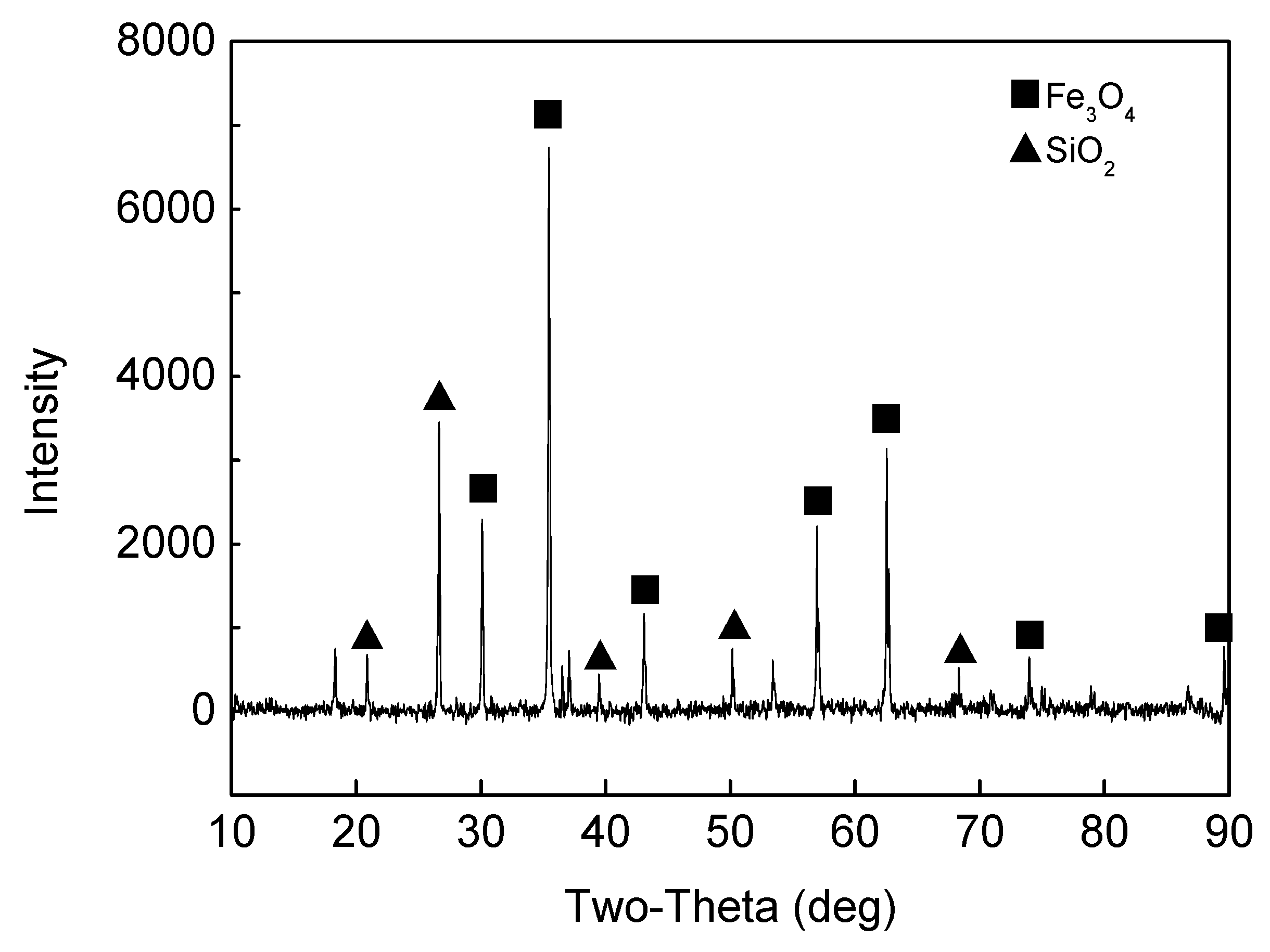
Figure 4.
Schematic diagram of the temperature profile control of the electric muffle furnace.

Figure 5.
Special crucible for the carbothermic reduction experiments in the tall pellets bed in the muffle furnace: (a) appearance of insulation crucible; (b) top view and size dimension of crucible.
Figure 5.
Special crucible for the carbothermic reduction experiments in the tall pellets bed in the muffle furnace: (a) appearance of insulation crucible; (b) top view and size dimension of crucible.

Figure 6.
Appearances of the total direct reduced iron (DRI) bed and each layer.

Figure 7.
Effect of C/O on metallization degree of direct reduced iron (DRI).
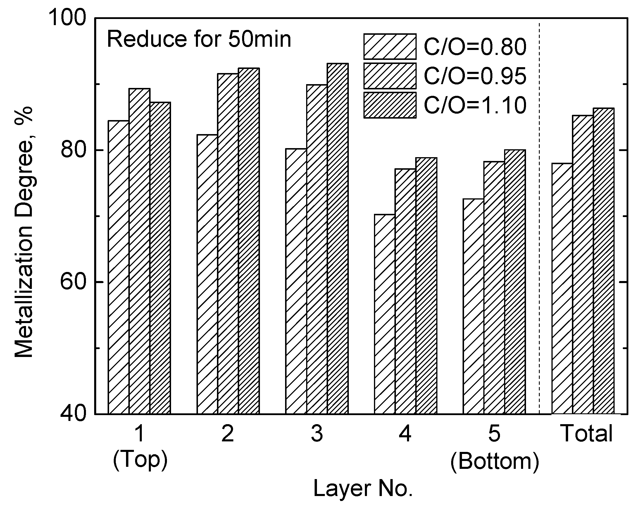
Figure 8.
Typical metallographic picture and energy disperse spectroscopy of direct reduced iron (DRI) (C/O = 0.95, 50 min, 2nd layer): (a) metallographic picture; (b) point A; (c) point B; (d) point C.
Figure 8.
Typical metallographic picture and energy disperse spectroscopy of direct reduced iron (DRI) (C/O = 0.95, 50 min, 2nd layer): (a) metallographic picture; (b) point A; (c) point B; (d) point C.


Figure 9.
Metallographic and element analysis of the direct reduced iron (DRI) in the 5th layer (C/O = 1.1): (a) metallographic picture; (b) element analysis.
Figure 9.
Metallographic and element analysis of the direct reduced iron (DRI) in the 5th layer (C/O = 1.1): (a) metallographic picture; (b) element analysis.
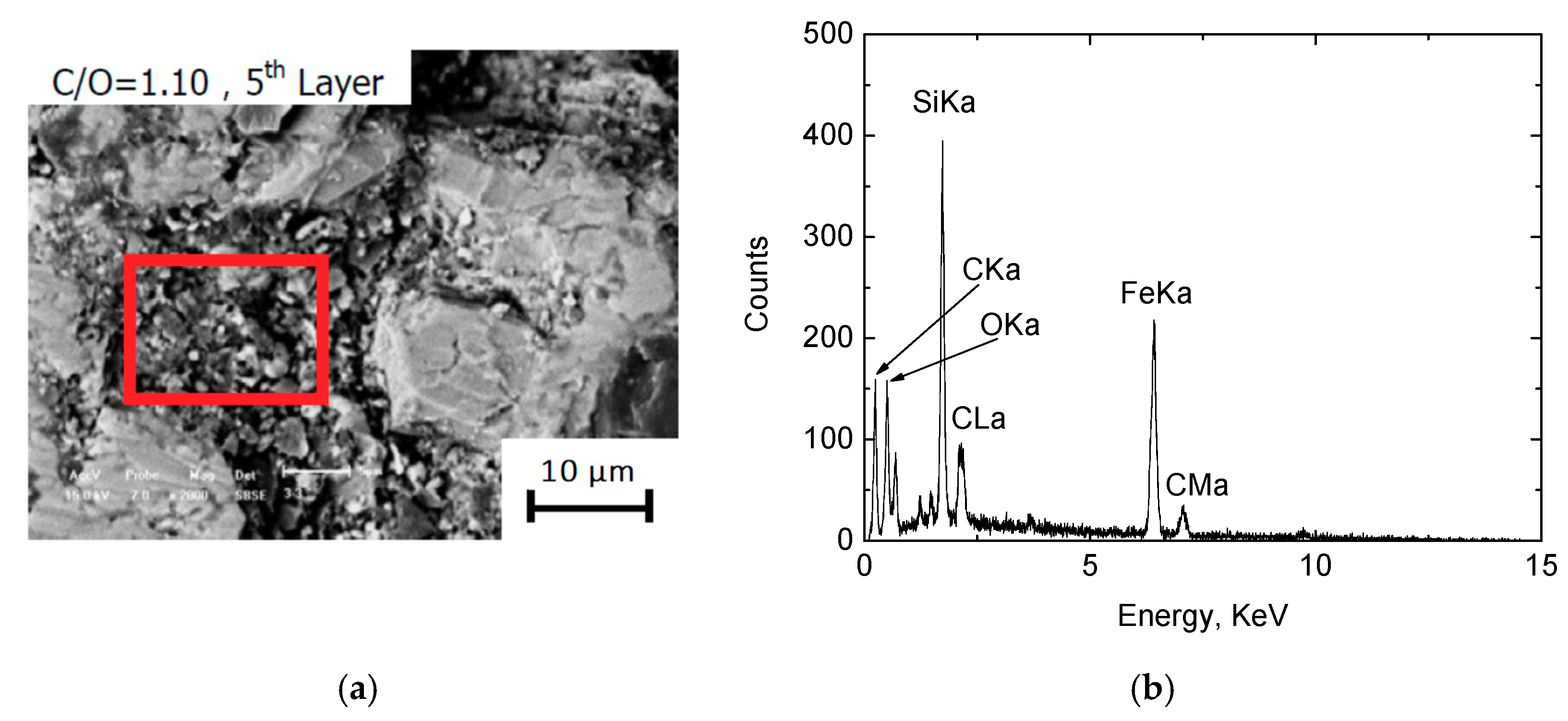
Figure 10.
Residual carbon of the direct reduced iron (DRI) in the 5th layer (bottom layer).

Figure 11.
Effect of reduction time (50 min and 60 min) on the metallization degree of direct reduced iron (DRI).
Figure 11.
Effect of reduction time (50 min and 60 min) on the metallization degree of direct reduced iron (DRI).
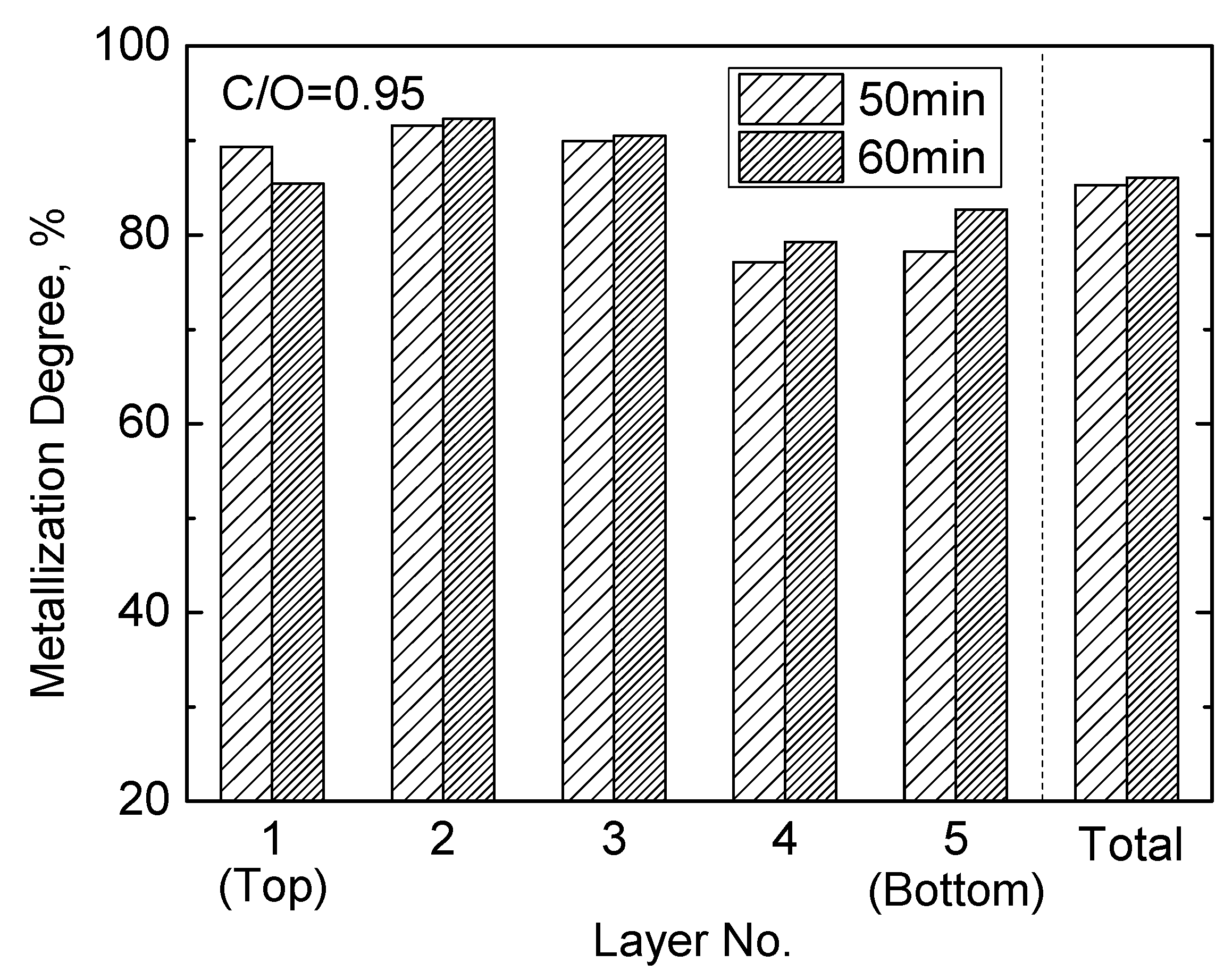
Figure 12.
Metallographic picture and energy spectrum of the 1st layer direct reduced iron (DRI) reduced for 60 min: (a) metallographic picture; (b) point A; (c) point B; (d) point C.
Figure 12.
Metallographic picture and energy spectrum of the 1st layer direct reduced iron (DRI) reduced for 60 min: (a) metallographic picture; (b) point A; (c) point B; (d) point C.
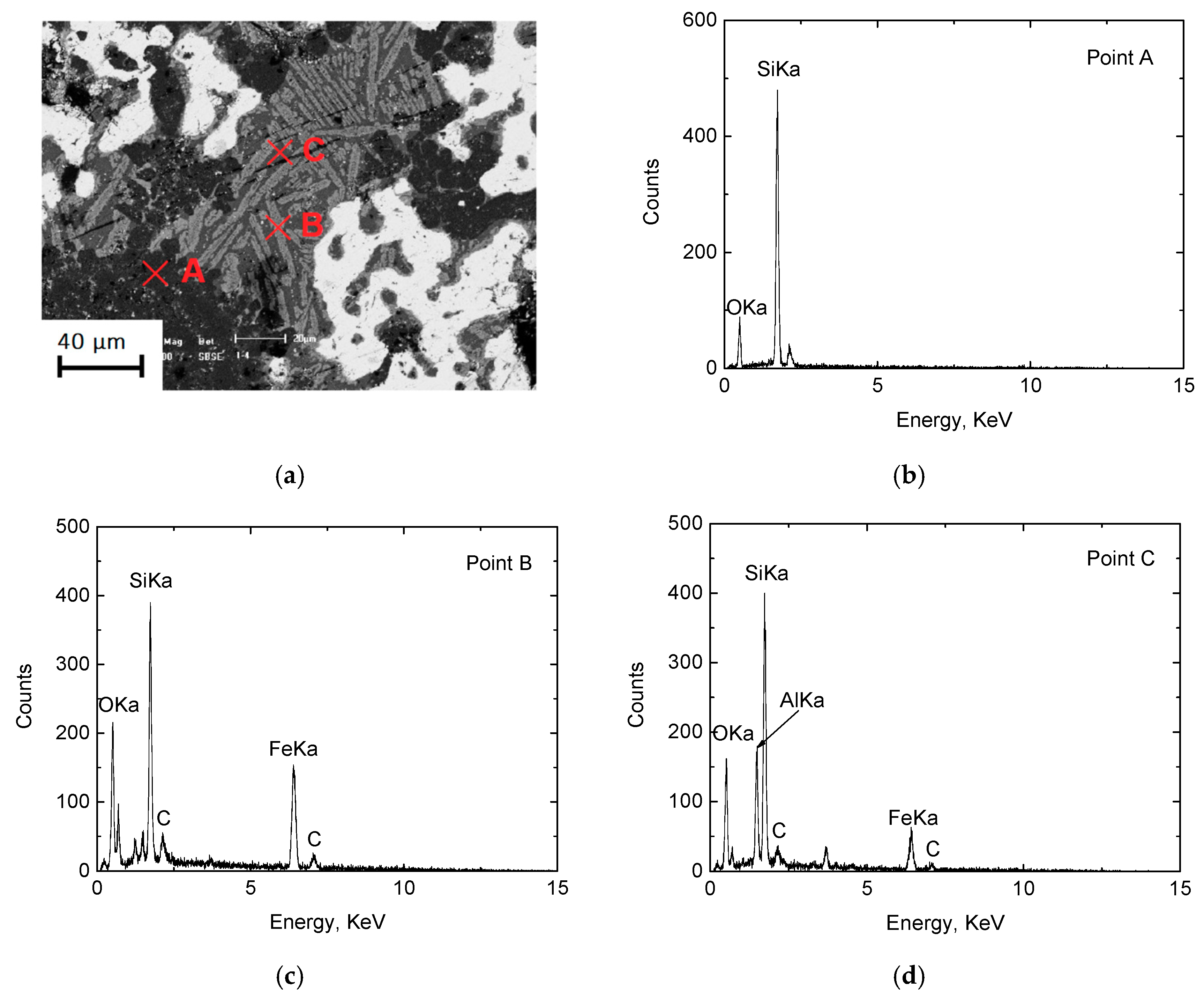
Figure 13.
Effects of pellets layers and reduction time on the productivity of metallic iron.

Figure 14.
Maximum productivity of metallic iron and corresponding reduction time for certain pellets layers.
Figure 14.
Maximum productivity of metallic iron and corresponding reduction time for certain pellets layers.
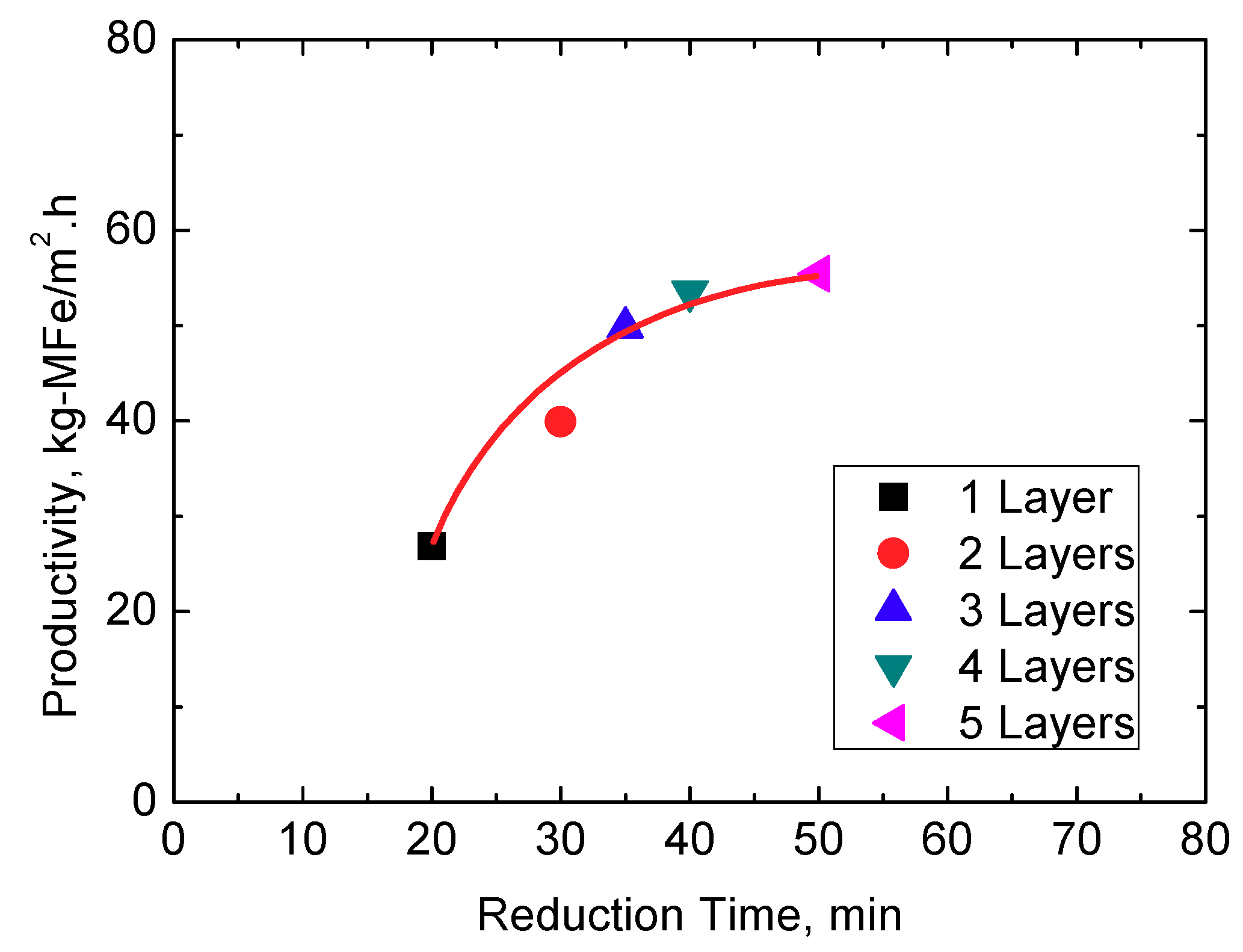
Figure 15.
Large space created in the pellets bed due to the shrinkage of DRI.

Table 1.
Chemical composition of iron ore concentrate (mass%).
| TFe | FeO | SiO2 | CaO | MgO | Al2O3 | LOI |
|---|---|---|---|---|---|---|
| 63.26 | 26.99 | 6.68 | 0.15 | 0.12 | 0.20 | −1.45 |
Table 2.
Proximate analysis and ash analysis of pulverized coal (mass%).
| Proximate Analysis | Ash Analysis | |||||||
|---|---|---|---|---|---|---|---|---|
| Fixed C | Total C | Ash | VM | SiO2 | Al2O3 | Fe2O3 | MgO | CaO |
| 61.31 | 77.5 | 9.38 | 26.00 | 49.14 | 29.98 | 10.22 | 0.70 | 5.37 |
© 2018 by the authors. Licensee MDPI, Basel, Switzerland. This article is an open access article distributed under the terms and conditions of the Creative Commons Attribution (CC BY) license (http://creativecommons.org/licenses/by/4.0/).
Share and Cite
MDPI and ACS Style
Jiang, X.; Ding, G.; Guo, H.; Gao, Q.; Shen, F. Carbothermic Reduction of Ore-Coal Composite Pellets in a Tall Pellets Bed. Minerals 2018, 8, 550. https://doi.org/10.3390/min8120550
AMA Style
Jiang X, Ding G, Guo H, Gao Q, Shen F. Carbothermic Reduction of Ore-Coal Composite Pellets in a Tall Pellets Bed. Minerals. 2018; 8(12):550. https://doi.org/10.3390/min8120550
Chicago/Turabian StyleJiang, Xin, Guangen Ding, He Guo, Qiangjian Gao, and Fengman Shen. 2018. "Carbothermic Reduction of Ore-Coal Composite Pellets in a Tall Pellets Bed" Minerals 8, no. 12: 550. https://doi.org/10.3390/min8120550
Note that from the first issue of 2016, this journal uses article numbers instead of page numbers. See further details here.