An Upper Bound Energy Formulation of Free-Chip Machining with Flat Chips and an Alternative Method of Determination of Cutting Forces without Using the Merchant’s Circle Diagram


 , and
, and 
Abstract
1. Introduction
2. The Generalized Upper Bound Technique
3. Upper Bound Analysis of Orthogonal Machining
4. Results and Discussion
5. Conclusions
Author Contributions
Funding
Data Availability Statement
Conflicts of Interest
Nomenclature
| b = width of the work piece |
| J* = total energy dissipation rate |
| k = yield stress in shear of the work material |
| to = uncut chip thickness |
| tchip = chip thickness |
| m = friction factor for the shear friction condition |
| u* = prescribed velocity on the surface Su |
| vc = cutting velocity |
| Vchip = chip velocity |
| vi = velocity in the direction of the specified traction Ti on the surface ST |
| vR = velocity in the direction of the resultant tool force R |
| |Δv| = velocity jump across a surface of velocity discontinuity |
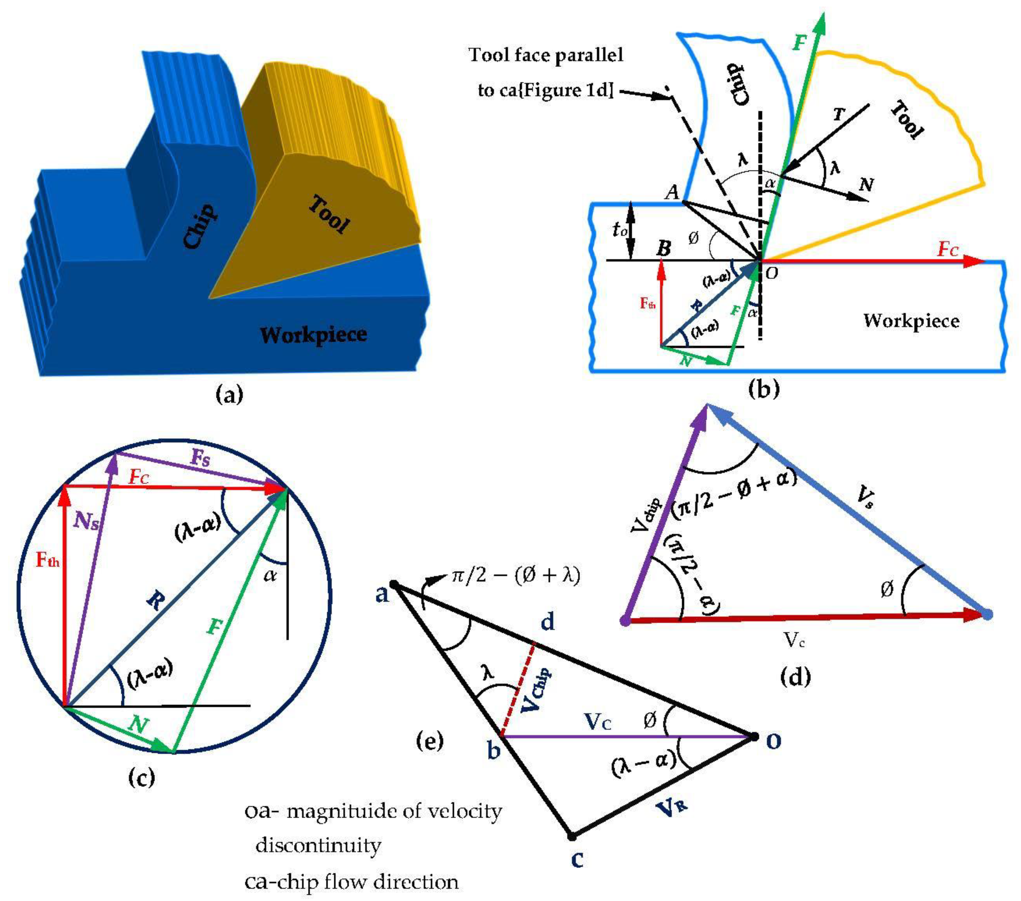
| F, N = friction force and normal force on the tool face (Figure 1a,b) |
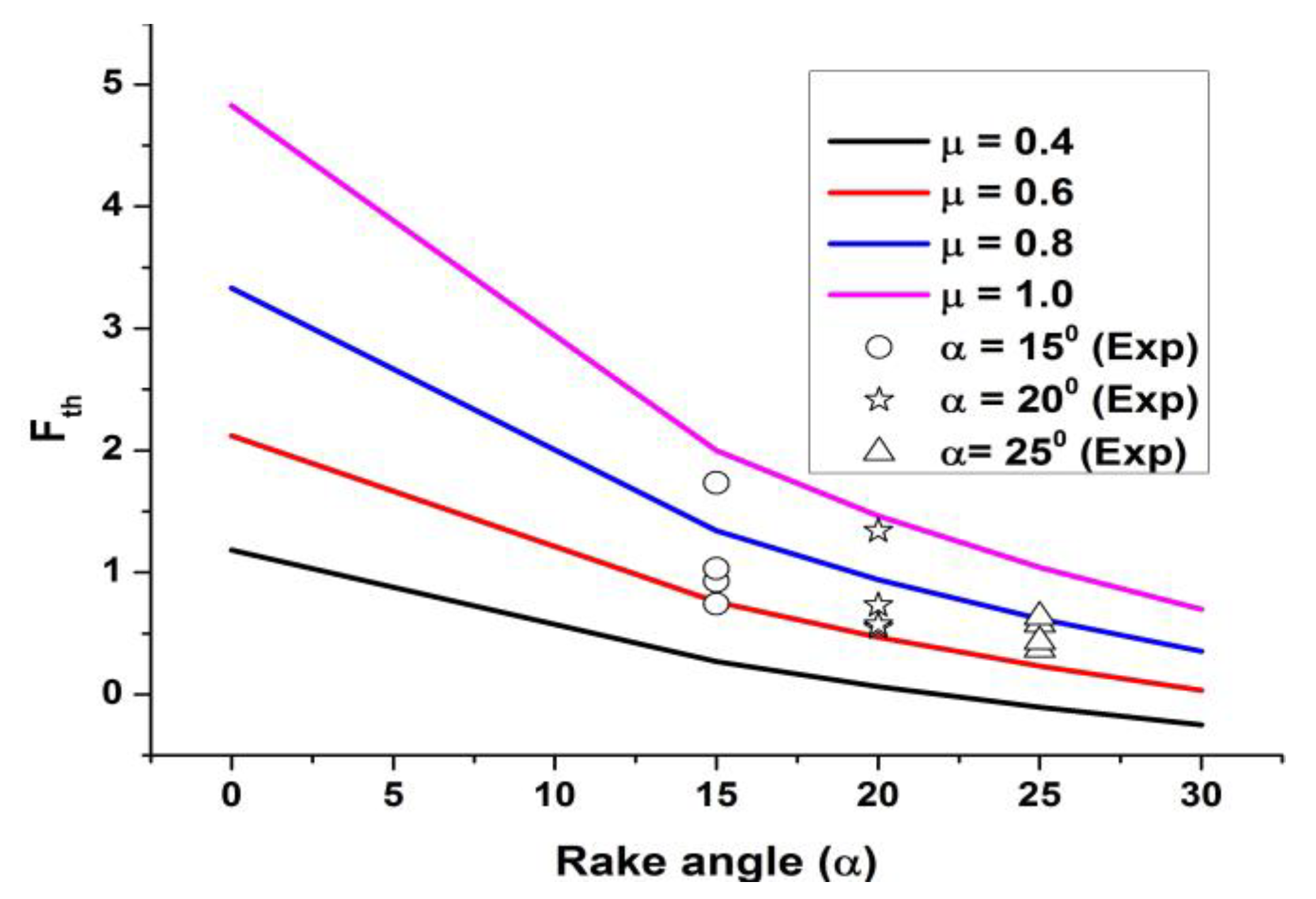
| Fc, Fth = tool cutting force and the thrust force (Figure 1a,b) |
| Fs, Ns = shear force and normal force on the shear plane (Figure 1a,b) |
| Ls = length of the shear plane |
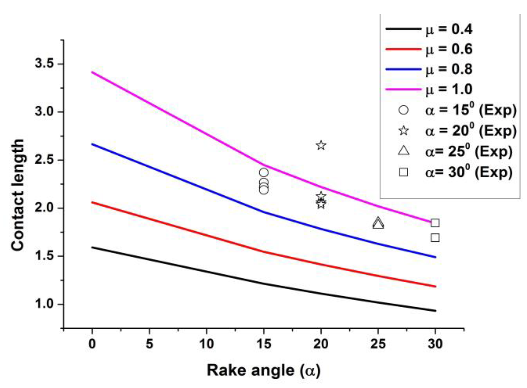
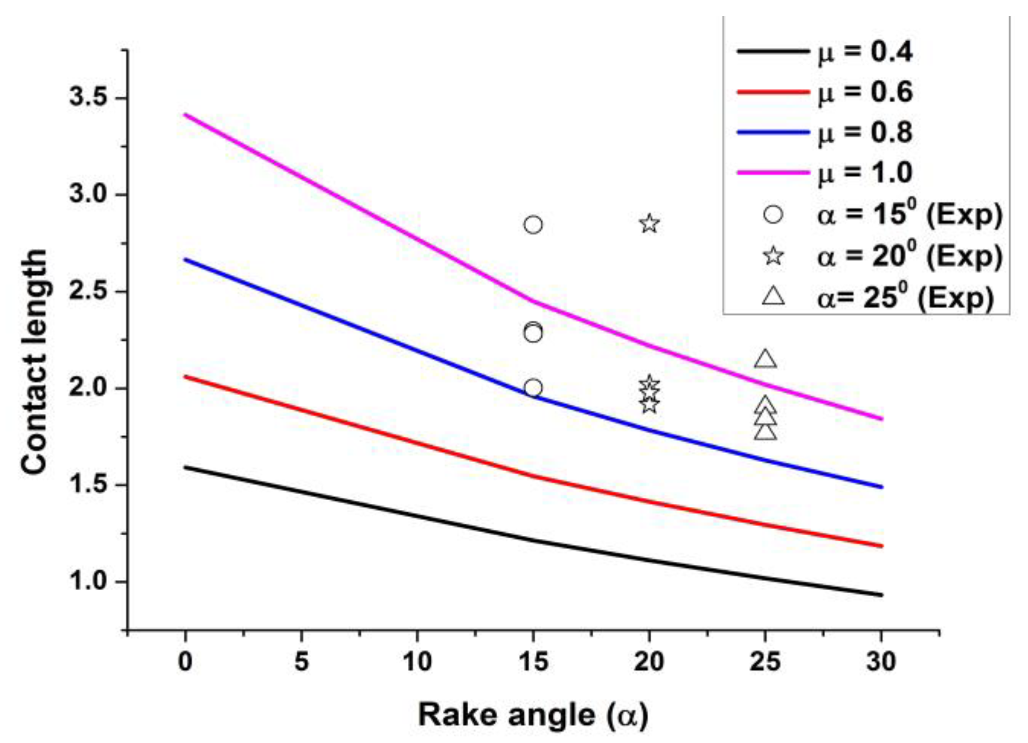
| Lc = tool/chip contact length |
| R = resultant of the above three pairs of forces (Figure 1a,b) |
| SF = surface across which there is a discontinuity in velocity (Equation (1)) |
| ST = surface where traction Ti is specified (Equation (1)) |
| Su = surface with specified velocity u* (Equation (1)) |
| Ti = surface traction on the surface ST (Equation (1)) |
| Tu = traction on surface Su (to be calculated) (Equation (1)) |
| α = tool rake angle |
| εij = strain rate |
| λ = angle of friction (tanλ = µ) |
| µ = coefficient of friction at chip-tool interface |
| ϕ = angle made by the shear plane with the direction of the tool travel |
| σo = yield stress in compression of the work material |
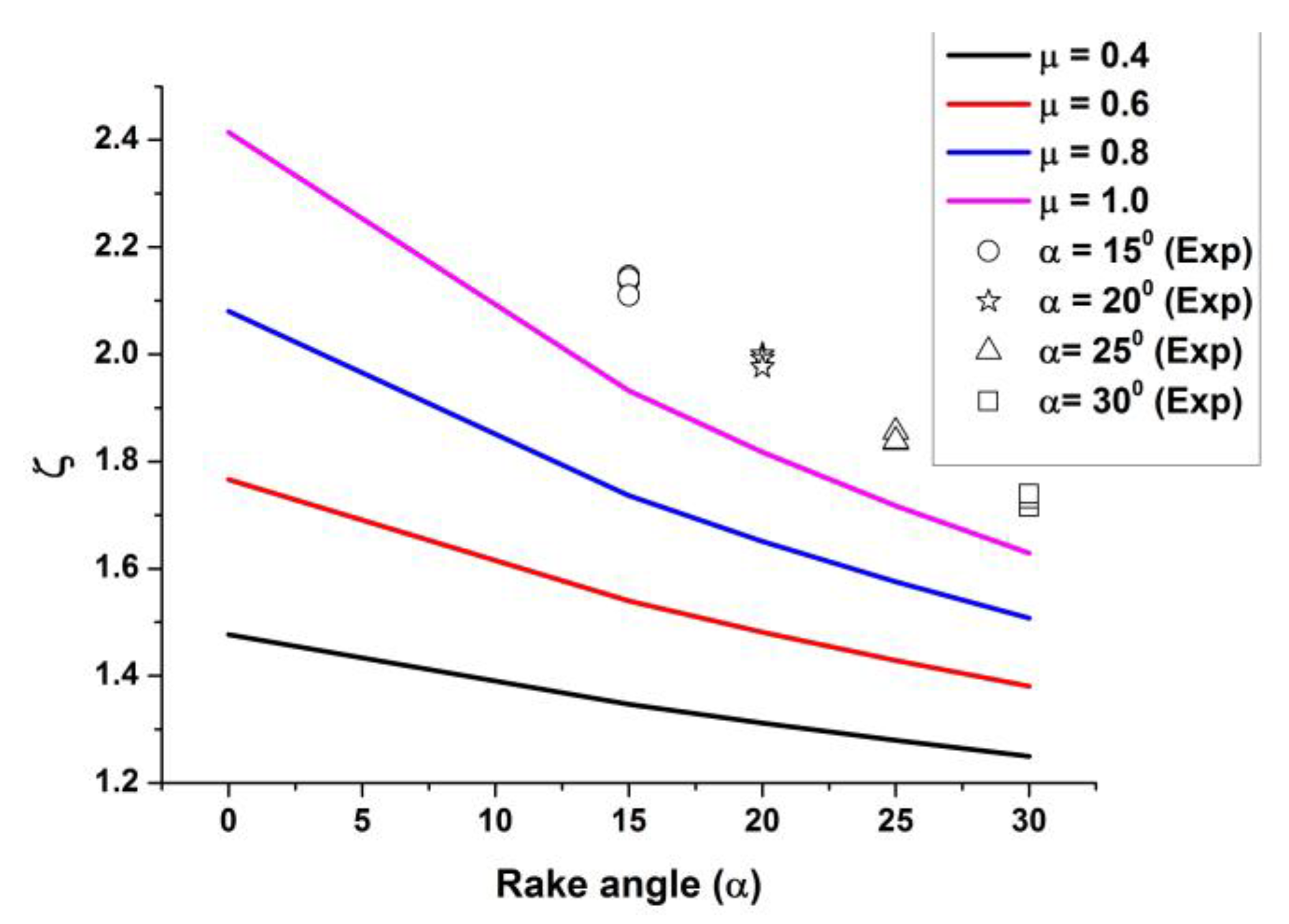
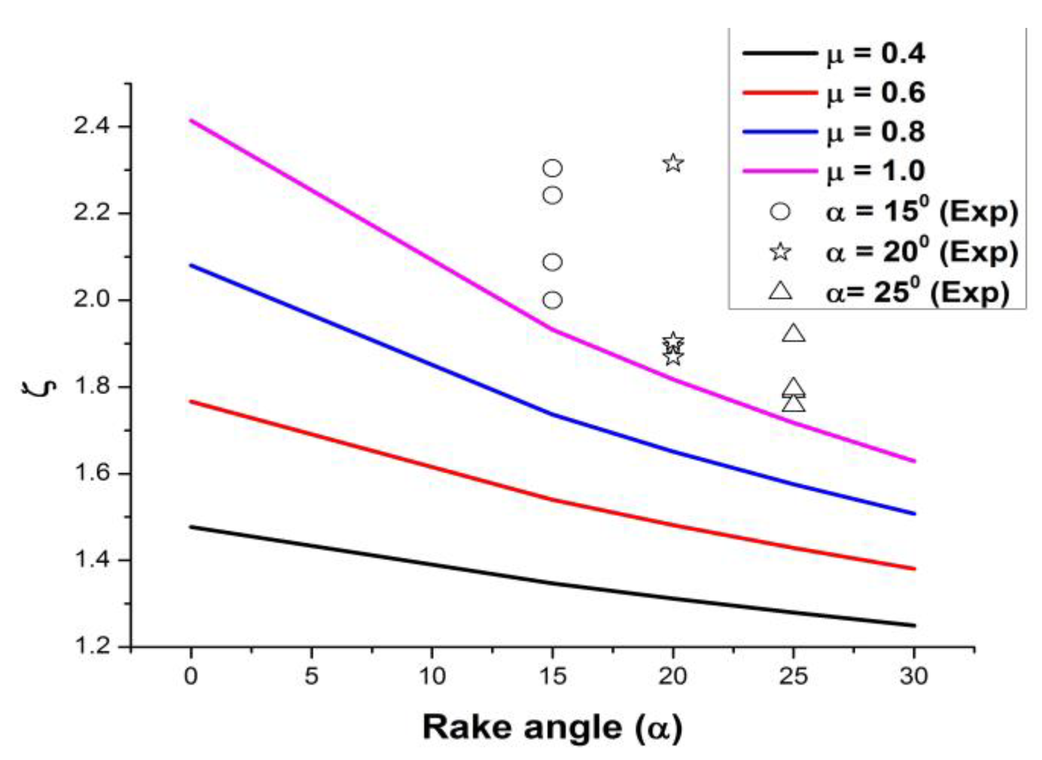
| ξ = chip thickness ratio |
| τ = frictional traction |
References
- Shaw, M.C. Metal Cutting Principles; Oxford University Press: Oxford, UK, 2006. [Google Scholar]
- Lee, E.H.; Shaffer, B.W. The theory of plasticity applied to a problem of machining. Trans ASME 1951, 73, 405–413. [Google Scholar] [CrossRef] [Scilit]
- Kudo, H. Some new ship line solution for two dimensional steady state machining. Int. J. Mech. Sci. 1965, 7, 43–55. [Google Scholar] [CrossRef] [Scilit]
- Dewhurst, P. On the Non-Uniqueness of the Machining Process. Proc. R. Soc. Lond. Ser. A 1978, 360, 587–610. [Google Scholar]
- Maity, K.P.; Das, N.S. A class of slipline field solutions for metal machining with slipping and sticking contact at the chip-tool interface. Int. J. Mech. Sci. 2001, 43, 3435–3452. [Google Scholar] [CrossRef] [Scilit]
- Das, N.S.; Dundur, S.T. A Slipline Field Analysis of Free-Chip Orthogonal Machining With Adhesion Friction at Rake Face. J. Mach. Sci. Technol. 2006, 10, 371–378. [Google Scholar] [CrossRef] [Scilit]
- Fang, N.; Jawahir, I.S.; Oxloy, P.L.B. A universal slip line model with curled chip formation and a restricted contact tool. Int. J. Mech. Sci. 2001, 43, 557–580. [Google Scholar] [CrossRef] [Scilit]
- Fang, N. Machining with tool–chip contact on the tool secondary rake face—Part I: A new slip-line model. Int. J. Mech. Sci. 2002, 44, 2337–2354. [Google Scholar] [CrossRef] [Scilit]
- Fang, N. Slip line modeling of machining with a rounded edge tool part I: New model and theory. J. Mech. Phys. Solids 2003, 51, 715–742. [Google Scholar] [CrossRef] [Scilit]
- Yu, L.; Yong, H. Combined effect of flank and crater wear on cutting force modeling in orthogonal machining—Part I:Model development. Mach. Sci. Technol. 2010, 14, 1–23. [Google Scholar]
- Fang, N.; Jawahir, I.S. A new methodology for determining the stress state of the plastic region in machining with restricted contact tool. Int. J. Mech. Sci. 2001, 43, 1747–1770. [Google Scholar] [CrossRef] [Scilit]
- Fang, N.; Jawahir, I.S. An analytical predictive model and experimental validation for machining with grooved tools incorporating the effect of strains, strain rates and temperatures. Ann. CIRP 2002, 51, 83–86. [Google Scholar] [CrossRef] [Scilit]
- Wang, H.; To, S.; Chan, C.Y.; Cheung, C.F.; Lee, W.B. A study of regularly spaced shear bands and morphology of serrated chip formation in microcutting process. J. Scr. Mater. 2010, 63, 227–230. [Google Scholar] [CrossRef] [Scilit]
- Jing, C.; Wang, J.; Zhang, C.; Sun, Y.; Shi, Z. Influence of size effect on the dynamic mechanical properties of OFHC copper at micro/meso scales. Int. J. Adv. Manuf. Technol. 2022, 120, 4775–4789. [Google Scholar] [CrossRef] [Scilit]
- Zhang, J.; Lee, J.Y.; Wang, H. Microstructure evaluation of shear bands of microcutting chips in AA6061 alloy under the mechanochemical effect. J. Mater. Sci. Technol. 2021, 91, 178–186. [Google Scholar] [CrossRef] [Scilit]
- Chodor, J.; Zurawski, L. Investigations on the chip shape and its upsetting and coverage ratios in partial symmetric face milling process of aluminium alloyAW-7075 and the simulation of the process with the use of FEM. Adv. Mech. Theor. Comput. Interdiscip. 2016, 121–124. [Google Scholar] [CrossRef] [Scilit]
- Komanduri, R.; Brown, R.H. On the mechanics of chip segmentation in machining. Trans ASME J Engg. Ind. 1981, 103, 33–337. [Google Scholar] [CrossRef] [Scilit]
- Das, N.S.; Dundur, S.T. Slipline field solutions for metal machining with adhesion friction and elastic effects at the chip-tool contact region. Proc. Inst. Mech. Eng. Part B J. Eng. Manuf. 2005, 219, 57–62. [Google Scholar] [CrossRef] [Scilit]
- Das, N.S.; Dundur, S.T. Slipline field analysis of free-chip machining with a tool with flank wear. Int. J. Manuf. Sci. Technol. 2006, 8, 60–68. [Google Scholar]
- Zou, G.P.; Seethaler, R.I. The extension of a simple predictive model for orthogonal cutting to include flow below the cutting edge. Proc. Inst. Mech. Eng. Part B J. Eng. Manuf. 2011, 225, 1568–1578. [Google Scholar] [CrossRef] [Scilit]
- Waldorf, D.J.; Devor, R.E.; Kapoor, S.G. A slip line field for ploughing during orthogonal cutting. Transaction of ASME. Journal of manufacturing science and engineering. ASME 1998, 120, 693–699. [Google Scholar]
- Iwata, K.; Osakada, K.; Terasaka, Y. Process Modeling of Orthogonal Cutting by the Rigid-Plastic Finite Element Method. J. Eng. Mater. Technol. 1984, 6, 132–138. [Google Scholar] [CrossRef] [Scilit]
- Kim, K.W.; Lee, W.Y.; Sih, H. A finite element analysis for machining with the tool edge considered. J. Mater. Process Tech. 1997, 86, 45–55. [Google Scholar]
- Strenkowski, J.S.; Athavale, S.M. A Partially Constrained Eulerian Orthogonal Cutting Model for Chip Control Tools. J. Manuf. Sci. Eng. 1997, 119, 681–688. [Google Scholar] [CrossRef] [Scilit]
- Strenkowski, J.S.; Carroll, J.T. A Finite Element Model of Orthogonal Metal Cutting. J. Eng. Ind. 1985, 107, 349–354. [Google Scholar] [CrossRef] [Scilit]
- Shinozuku, J.S.; Obikawa, T.; Shirakashi, T. Chip breaking analysis from the view point of the optimum cutting tool geometry design. J. Mater. Process. Technol. 1996, 62, 345–351. [Google Scholar] [CrossRef] [Scilit]
- Childs, T.; Maekawa, K.; Obikawa, T.; Yamane, Y. Metal Machining: Theory and Applications; Arnold: London, UK, 2000. [Google Scholar]
- Iqbal, S.A.; Nartivenga, P.T.; Sheikh, M.A. An investigative study of the inter face heat transfer coefficient for finite element modelling of high speed machining. Proc. Inst. Mech. Eng. Part B J. Eng. Manuf. 2008, 222, 1405–1413. [Google Scholar] [CrossRef] [Scilit]
- Afsharhanaec, A.; Rebaioli, L.; Parenti, P.; Annoni, M. Finite Element Modelling of micro-orthogonal cutting process with dead metal cap. Proc. Inst. Mech. Eng. Part B J. Eng. Manuf. 2018, 323, 351. [Google Scholar]
- Li, X.; Kopalinsky, E.M.; Oxley, P.L.B. A numerical method for determining temperature distributions in machining with coolant Part 1: Modelling the process. Proceding Inst. Mech. Eng. 1995, 205, 33–41. [Google Scholar] [CrossRef] [Scilit]
- Merchant, M.E. Basic mechanics of metal cutting process. J Appl. Mech. 1944, 15, 168–175. [Google Scholar] [CrossRef] [Scilit]
- Atkins, A.G. Modelling metal cutting using modern ductile fracture mechanics, quantitative explanation for some long standing problems. Int. J. Mech. Sci. 2003, 45, 373–396. [Google Scholar] [CrossRef] [Scilit]
- Prager, W.; Hodge, P.C. Theory of Perfectly Plastic Solids; Chapman and Hall Ltd.: London, UK, 1951. [Google Scholar]
- Drucker, D.C.; Prager, W.; Greemberg, H.J. Extended limit design theorems for continuous media. J. Appl. Math. 1952, 9, 381–386. [Google Scholar] [CrossRef] [Scilit]
- Collins, I.F. The upper bound theorem for rigid plastic, solids generalized to include coulomb friction. J. Mech. Phys. Solids 1969, 17, 323. [Google Scholar] [CrossRef] [Scilit]
- Eggleston, D.M.; Herzog, R.; Thomsen, E.G. Observations on the angle relationships in metal cutting. J. Eng. Ind. 1959, 81, 263–279. [Google Scholar] [CrossRef] [Scilit]
- Kudo, H. Some analytical and experimental studies of axi-symmetric cold forging and extrusion Part-I. Int. J. Mech. Sci. 1960, 2, 102. [Google Scholar] [CrossRef] [Scilit]
- Solhjoo, S. A note on barrel compression test computer. Mater. Sci. 2010, 49, 435. [Google Scholar]
- Westwood, D.; Wallance, J.F. Upper bound values for the loads on a rigid plastic body in plane strain. Int. J. Mech. Sci. 1960, 2, 179. [Google Scholar] [CrossRef] [Scilit]
- Green, J.W.; Wallance, J.F. Estimation of load and torque in the hot rolling process. Int. J. Mech. Sci. 1962, 4, 136. [Google Scholar] [CrossRef] [Scilit]
- Green, J.W.; Sparling, L.G.M.; Wallance, J.F. Shear plane theories of hot and cold rolling. Int. J. Mech. Sci. 1964, 6, 219. [Google Scholar] [CrossRef] [Scilit]
- Das, N.S.; Joardar, H.; Behera, M.R.B.C.; Maity, K.P. Generalised upper bound method and its application to some plane strain compression and extrusion problems. Adv. Technol. Mater. 2021, 46, 7–18. [Google Scholar]
- Hill, R. The mechanics of machining: A new approach. J. Mech. Phys. Solids 1954, 47, 47–53. [Google Scholar] [CrossRef] [Scilit]
- Childs, T.H.C.; Mahadi, M.I. On the stress distribution between the chip and tool during metal turning. Ann. CIRP 1989, 38, 55–58. [Google Scholar] [CrossRef] [Scilit]


Disclaimer/Publisher’s Note: The statements, opinions and data contained in all publications are solely those of the individual author(s) and contributor(s) and not of MDPI and/or the editor(s). MDPI and/or the editor(s) disclaim responsibility for any injury to people or property resulting from any ideas, methods, instructions or products referred to in the content. |
© 2023 by the authors. Licensee MDPI, Basel, Switzerland. This article is an open access article distributed under the terms and conditions of the Creative Commons Attribution (CC BY) license (https://creativecommons.org/licenses/by/4.0/).
Share and Cite
Joardar, H.; Das, N.S.; Haldar, B.; Maity, K.; Abdulrahman Alsaleh, N.; Ataya, S. An Upper Bound Energy Formulation of Free-Chip Machining with Flat Chips and an Alternative Method of Determination of Cutting Forces without Using the Merchant’s Circle Diagram. Machines 2023, 11, 853. https://doi.org/10.3390/machines11090853
Joardar H, Das NS, Haldar B, Maity K, Abdulrahman Alsaleh N, Ataya S. An Upper Bound Energy Formulation of Free-Chip Machining with Flat Chips and an Alternative Method of Determination of Cutting Forces without Using the Merchant’s Circle Diagram. Machines. 2023; 11(9):853. https://doi.org/10.3390/machines11090853
Chicago/Turabian StyleJoardar, Hillol, Nitai Sundar Das, Barun Haldar, Kalipada Maity, Naser Abdulrahman Alsaleh, and Sabbah Ataya. 2023. "An Upper Bound Energy Formulation of Free-Chip Machining with Flat Chips and an Alternative Method of Determination of Cutting Forces without Using the Merchant’s Circle Diagram" Machines 11, no. 9: 853. https://doi.org/10.3390/machines11090853
APA StyleJoardar, H., Das, N. S., Haldar, B., Maity, K., Abdulrahman Alsaleh, N., & Ataya, S. (2023). An Upper Bound Energy Formulation of Free-Chip Machining with Flat Chips and an Alternative Method of Determination of Cutting Forces without Using the Merchant’s Circle Diagram. Machines, 11(9), 853. https://doi.org/10.3390/machines11090853