Jarosite and Alunite in Ancient Terrestrial Sedimentary Rocks: Reinterpreting Martian Depositional and Diagenetic Environmental Conditions

Abstract
:1. Introduction and Background
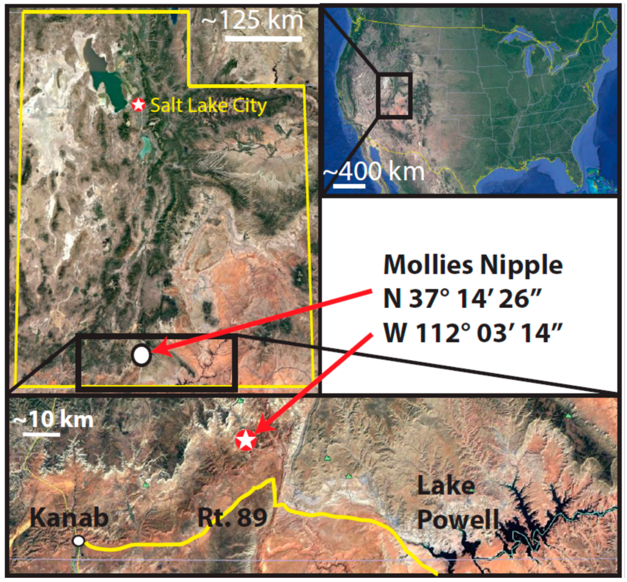
2. Geologic Setting
3. Purpose of Study
4. Methods
5. Results
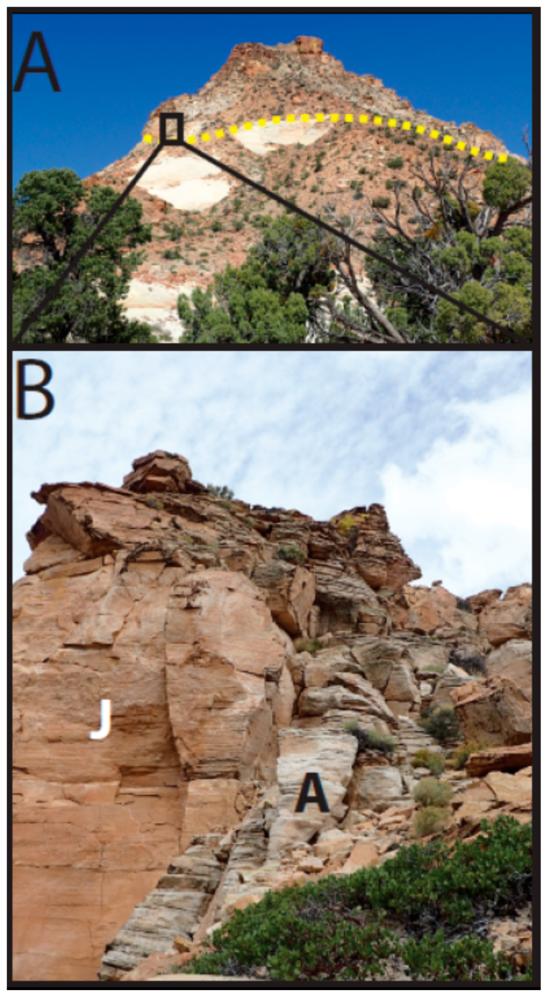
5.1. Field Study
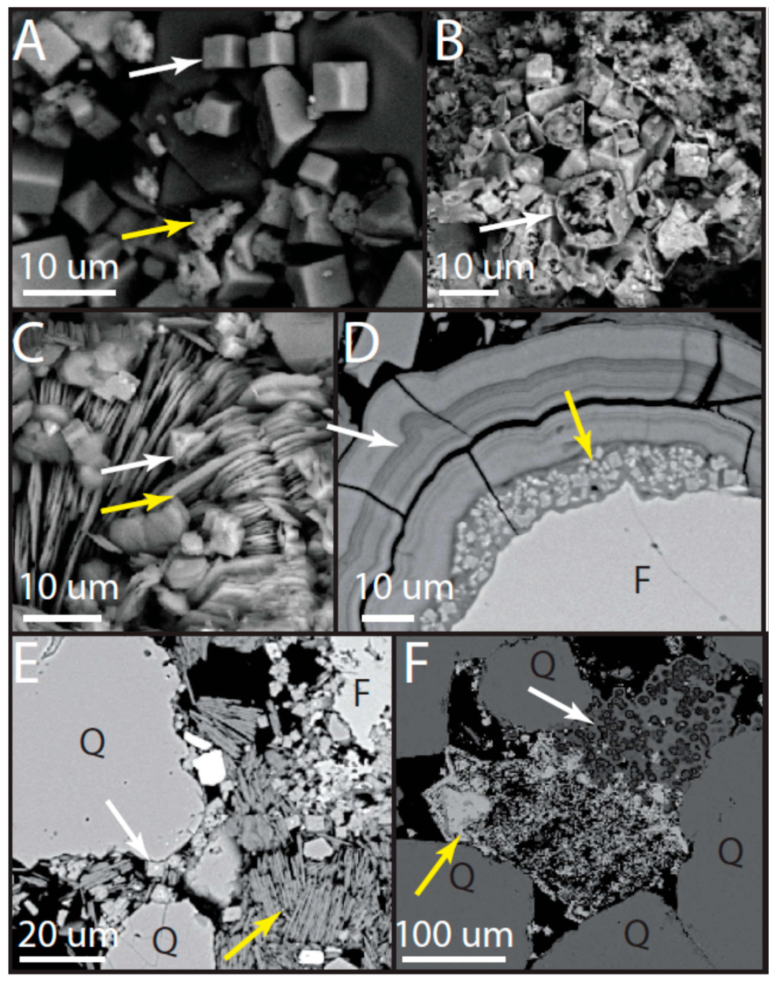
5.2. Mineralogy and Petrography
5.2.1. Navajo Sandstone
5.2.2. Lower Subunit of Caprock
5.2.3. Upper Subunit of Caprock
6. Interpretation
6.1. Stratigraphy
6.2. Paragenesis
6.2.1. Lower Subunit of Caprock
- Precompaction early precipitation of pyrite or siderite. This precompaction likely occurred based on large euhedral crystals that do not exhibit signs of displacive growth (Figure 9).
- Precipitation of illite, alunite, woodhouseite, and kaolinite.
- Rising pH (driven, in part, by dissolution of orthoclase, but also the evolution of the fluid discussed below) caused a second phase of precipitation of laminated, second-generation zeolitic mineral.
- Late-stage infilling of retained porosity by a third-generation event that precipitated illite.
6.2.2. Upper Subunit of Caprock
- Jarosite and alunite + kaolinite precipitation throughout the unit. This is interpreted because of precompaction features such as “floating” grains in cement and the preferential preservation of jarosite and alunite that occurs in the wind ripple laminae. Additionally, the presence of cores of jarosite within alunite and vice versa show multistage precipitation events.
- Preferential removal of jarosite cement within grain flow laminae and further degradation of jarosite during burial diagenesis.
- Late-stage diagenesis to weathering results in hematite precipitation in spots within the jarosite diagenetic facies.
7. Discussion
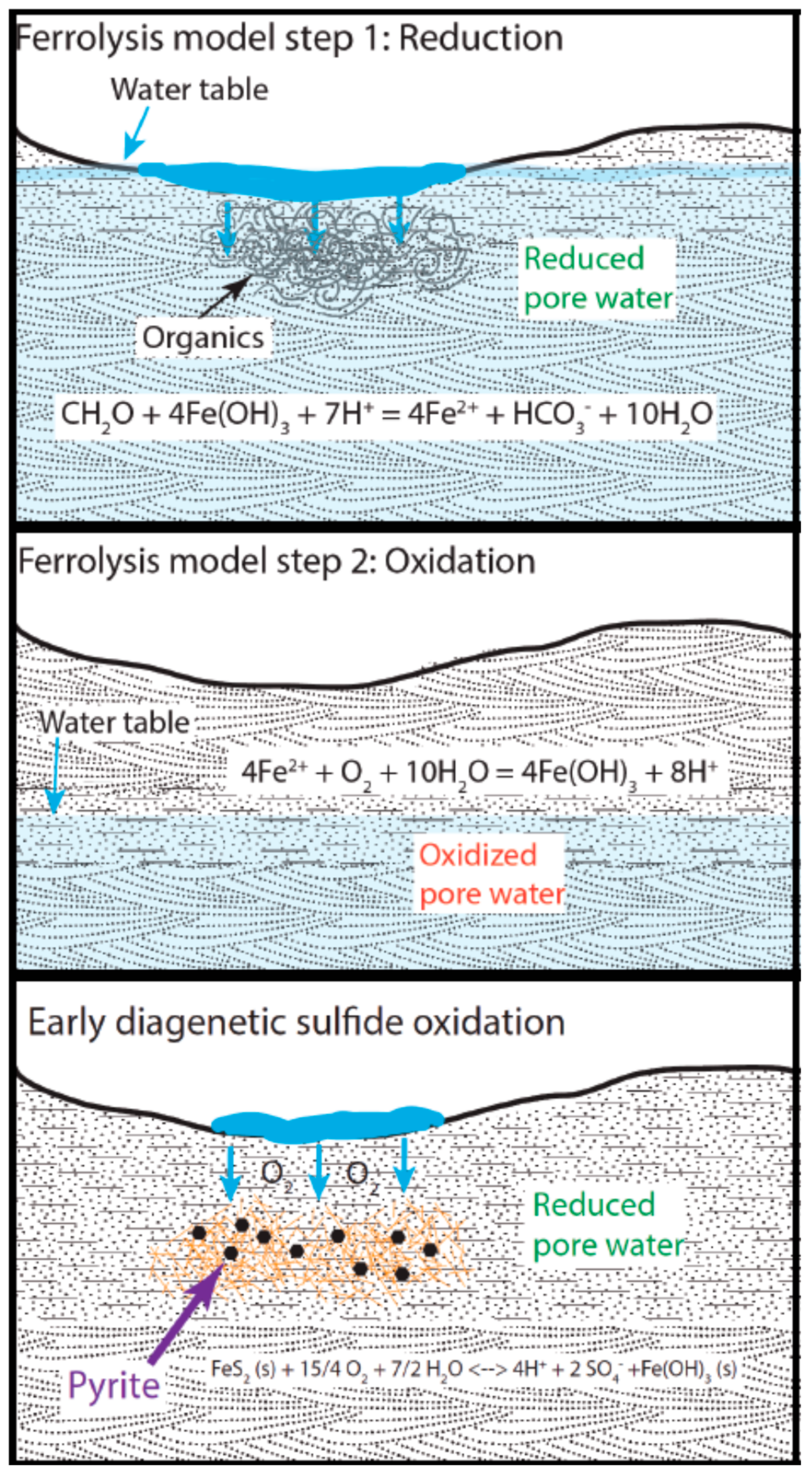
7.1. Evolved Groundwater by the Ferrolysis Model
7.2. Jarosite and Alunite Stabilization
Supplementary Materials
Author Contributions
Funding
Acknowledgments
Conflicts of Interest
References
- Ehlmann, B.L.; Edwards, C.S. Mineralogy of the Martian surface. Annu. Rev. Earth Planet. Sci. 2014, 42, 291–315. [Google Scholar] [CrossRef]
- Nachon, M.; Clegg, S.; Mangold, N.; Schröder, S.; Kah, L.; Dromart, G.; Ollila, A.; Johnson, J.; Oehler, D.; Bridges, J. Calcium sulfate veins characterized by ChemCam/Curiosity at Gale crater, Mars. J. Geophys. Res. Planets 2014, 119, 1991–2016. [Google Scholar] [CrossRef] [Green Version]
- Arvidson, R.E.; Bell, J.F.; Catalano, J.G.; Clark, B.C.; Fox, V.K.; Gellert, R.; Grotzinger, J.P.; Guinness, E.A.; Herkenhoff, K.E.; Knoll, A.H.; et al. Mars Reconnaissance Orbiter and Opportunity observations of the Burns formation: Crater hopping at Meridiani Planum. J. Geophys. Res. Planets 2015, 120, 429–451. [Google Scholar] [CrossRef] [Green Version]
- Dill, H.G. The geology of aluminum phosphates and sulphates of the alunite supergroup: A review. Earth Sci. Rev. 2001, 53, 25–93. [Google Scholar] [CrossRef]
- Klingelhöfer, G.; Morris, R.V.; Bernhardt, B.; Schröder, C.; Rodionov, D.S.; De Souza, P.; Yen, A.; Gellert, R.; Evlanov, E.; Zubkov, B. Jarosite and hematite at Meridiani Planum from Opportunity’s Mössbauer spectrometer. Science 2004, 306, 1740–1745. [Google Scholar] [CrossRef] [PubMed]
- McLennan, S.M.; Bell, J.; Calvin, W.; Christensen, P.; Clark, B.D.; De Souza, P.; Farmer, J.; Farrand, W.; Fike, D.; Gellert, R. Provenance and diagenesis of the evaporite-bearing Burns formation, Meridiani Planum, Mars. Earth Planet. Sci. Lett. 2005, 240, 95–121. [Google Scholar] [CrossRef]
- Morris, R.V.; Klingelhoefer, G.; Schröder, C.; Rodionov, D.S.; Yen, A.; Ming, D.W.; De Souza, P.; Wdowiak, T.; Fleischer, I.; Gellert, R. Mössbauer mineralogy of rock, soil, and dust at Meridiani Planum, Mars: Opportunity’s journey across sulfate-rich outcrop, basaltic sand and dust, and hematite lag deposits. J. Geophys. Res. Planets 2006, 111. [Google Scholar] [CrossRef]
- Milliken, R.E.; Swayze, G.A.; Arvidson, R.E.; Bishop, J.L.; Clark, R.N.; Ehlmann, B.L.; Green, R.O.; Grotzinger, J.P.; Morris, R.; Murchie, S.L. Opaline silica in young deposits on Mars. Geology 2008, 36, 847–850. [Google Scholar] [CrossRef]
- Farrand, W.H.; Glotch, T.D.; Rice, J.W., Jr.; Hurowitz, J.A.; Swayze, G.A. Discovery of jarosite within the Mawrth Vallis region of Mars: Implications for the geologic history of the region. Icarus 2009, 204, 478–488. [Google Scholar] [CrossRef]
- Wray, J.; Milliken, R.; Dundas, C.; Swayze, G.; Andrews-Hanna, J.; Baldridge, A.; Chojnacki, M.; Bishop, J.; Ehlmann, B.; Murchie, S.L. Columbus crater and other possible groundwater-fed paleolakes of Terra Sirenum, Mars. J. Geophys. Res. Planets 2011, 116. [Google Scholar] [CrossRef]
- Ehlmann, B.L.; Mustard, J.F. An in-situ record of major environmental transitions on early Mars at Northeast Syrtis Major. Geophys. Res. Lett. 2012, 39. [Google Scholar] [CrossRef]
- Thollot, P.; Mangold, N.; Ansan, V.; Le Mouelic, S.; Milliken, R.E.; Bishop, J.L.; Weitz, C.M.; Roach, L.H.; Mustard, J.F.; Murchie, S.L. Most Mars minerals in a nutshell: Various alteration phases formed in a single environment in Noctis Labyrinthus. J. Geophys. Res. Planets 2012, 117. [Google Scholar] [CrossRef] [Green Version]
- Cull, S.; Cravotta, C.A., III; Klinges, J.G.; Weeks, C. Spectral masking of goethite in abandoned mine drainage systems: Implications for Mars. Earth Planet. Sci. Lett. 2014, 403, 217–224. [Google Scholar] [CrossRef]
- Ehlmann, B.; Anderson, F.; Andrews-Hanna, J.; Catling, D.; Christensen, P.; Cohen, B.; Dressing, C.; Edwards, C.; Elkins-Tanton, L.; Farley, K. The sustainability of habitability on terrestrial planets: Insights, questions, and needed measurements from Mars for understanding the evolution of Earth-like worlds. J. Geophys. Res. Planets 2016, 121, 1927–1961. [Google Scholar] [CrossRef] [Green Version]
- Madden, M.E.; Bodnar, R.J.; Rimstidt, J.D. Jarosite as an indicator of water-limited chemical weathering on Mars. Nature 2004, 431, 821. [Google Scholar] [CrossRef] [PubMed]
- Elwood Madden, M.E.; Madden, A.S.; Rimstidt, J.D. How long was Meridiani Planum wet? Applying a jarosite stopwatch to determine the duration of aqueous diagenesis. Geology 2009, 37, 635–638. [Google Scholar] [CrossRef]
- Elwood Madden, M.; Madden, A.; Rimstidt, J.; Zahrai, S.; Kendall, M.; Miller, M. Jarosite dissolution rates and nanoscale mineralogy. Geochim. Cosmochim. Acta 2012, 91, 306–321. [Google Scholar] [CrossRef]
- Pritchett, B.; Madden, M.E.; Madden, A. Jarosite dissolution rates and maximum lifetimes in high salinity brines: Implications for Earth and Mars. Earth Planet. Sci. Lett. 2012, 357, 327–336. [Google Scholar] [CrossRef]
- Miller, J.; Madden, A.E.; Phillips-Lander, C.; Pritchett, B.; Madden, M.E. Alunite dissolution rates: Dissolution mechanisms and implications for Mars. Geochim. Cosmochim. Acta 2016, 172, 93–106. [Google Scholar] [CrossRef]
- Fernández-Remolar, D.C.; Morris, R.V.; Gruener, J.E.; Amils, R.; Knoll, A.H. The Rio Tinto Basin, Spain: Mineralogy, sedimentary geobiology, and implications for interpretation of outcrop rocks at Meridiani Planum, Mars. Earth Planet. Sci. Lett. 2005, 240, 149–167. [Google Scholar] [CrossRef]
- Schiffman, P.; Zierenberg, R.; Marks, N.; Bishop, J.L.; Dyar, M.D. Acid-fog deposition at Kilauea volcano: A possible mechanism for the formation of siliceous-sulfate rock coatings on Mars. Geology 2006, 34, 921–924. [Google Scholar] [CrossRef]
- Bowen, B.B.; Benison, K.C. Geochemical characteristics of naturally acid and alkaline saline lakes in southern Western Australia. Appl. Geochem. 2009, 24, 268–284. [Google Scholar] [CrossRef] [Green Version]
- Norlund, K.L.; Baron, C.; Warren, L.A. Jarosite formation by an AMD sulphide-oxidizing environmental enrichment: Implications for biomarkers on Mars. Chem. Geol. 2010, 275, 235–242. [Google Scholar] [CrossRef]
- McHenry, L.J.; Chevrier, V.; Schröder, C. Jarosite in a Pleistocene East African saline-alkaline paleolacustrine deposit: Implications for Mars aqueous geochemistry. J. Geophys. Res. Planets 2011, 116. [Google Scholar] [CrossRef]
- Battler, M.M.; Osinski, G.R.; Lim, D.S.; Davila, A.F.; Michel, F.A.; Craig, M.A.; Izawa, M.R.; Leoni, L.; Slater, G.F.; Fairen, A.G. Characterization of the acidic cold seep emplaced jarositic Golden Deposit, NWT, Canada, as an analogue for jarosite deposition on Mars. Icarus 2013, 224, 382–398. [Google Scholar] [CrossRef] [Green Version]
- McCollom, T.M.; Hynek, B.M.; Rogers, K.; Moskowitz, B.; Berquó, T.S. Chemical and mineralogical trends during acid-sulfate alteration of pyroclastic basalt at Cerro Negro volcano and implications for early Mars. J. Geophys. Res. Planets 2013, 118, 1719–1751. [Google Scholar] [CrossRef] [Green Version]
- McCollom, T.M.; Ehlmann, B.L.; Wang, A.; Hynek, B.M.; Moskowitz, B.; Berquó, T.S. Detection of iron substitution in natroalunite-natrojarosite solid solutions and potential implications for Mars. Am. Mineral. 2014, 99, 948–964. [Google Scholar] [CrossRef]
- Bell, J.; Bowen, B. Fracture-focused fluid flow in an acid and redox-influenced system: Diagenetic controls on cement mineralogy and geomorphology in the Navajo Sandstone. Geofluids 2014, 14, 251–265. [Google Scholar] [CrossRef]
- Singh, M.; Rajesh, V.; Sajinkumar, K.; Sajeev, K.; Kumar, S. Spectral and chemical characterization of jarosite in a palaeolacustrine depositional environment in Warkalli Formation in Kerala, South India and its implications. Spectrochim. Acta Part A Mol. Biomol. Spectrosc. 2016, 168, 86–97. [Google Scholar] [CrossRef] [PubMed]
- Akai, J.; Kawamoto, K.; Akai, A.; Nakano, S. Biogenic contribution to the formation of iron ore in Gumma Iron Mine, central Japan. Proc. 30th Intl. Geol. Congr. 1997, 9, 199–208. [Google Scholar]
- Lueth, V.W.; Rye, R.O.; Peters, L. “Sour gas” hydrothermal jarosite: Ancient to modern acid-sulfate mineralization in the southern Rio Grande rift. Chem. Geol. 2005, 215, 339–360. [Google Scholar] [CrossRef]
- Hudson-Edwards, K.A.; Schell, C.; Macklin, M.G. Mineralogy and geochemistry of alluvium contaminated by metal mining in the Rio Tinto area, southwest Spain. Appl. Geochem. 1999, 14, 1015–1030. [Google Scholar] [CrossRef]
- Zimbelman, D.; Rye, R.O.; Breit, G. Origin of secondary sulfate minerals on active andesitic stratovolcanoes. Chem. Geol. 2005, 215, 37–60. [Google Scholar] [CrossRef] [Green Version]
- Papike, J.; Karner, J.; Shearer, C. Comparative planetary mineralogy: Implications of martian and terrestrial jarosite. A crystal chemical perspective. Geochim. Cosmochim. Acta 2006, 70, 1309–1321. [Google Scholar] [CrossRef]
- Doner, H.E.; Lynn, W.C. Carbonate, halide, sulfate, and sulfide minerals. In Minerals in Soil Environments; Soil Science Society of America: Madison, WI, USA, 1989; pp. 279–330. [Google Scholar]
- Tuttle, M.L.; Breit, G.N. Weathering of the New Albany Shale, Kentucky, USA: I. Weathering zones defined by mineralogy and major-element composition. Appl. Geochem. 2009, 24, 1549–1564. [Google Scholar] [CrossRef]
- Bell, J.H.; Bowen, B.B.; Martini, B.A. Imaging spectroscopy of jarosite cement in the Jurassic Navajo Sandstone. Remote Sens. Environ. 2010, 114, 2259–2270. [Google Scholar] [CrossRef]
- Beitler, B.; Chan, M.A.; Parry, W.T. Bleaching of Jurassic Navajo sandstone on Colorado Plateau Laramide highs: Evidence of exhumed hydrocarbon supergiants? Geology 2003, 31, 1041–1044. [Google Scholar] [CrossRef]
- Beitler, B.; Parry, W.; Chan, M.A. Fingerprints of fluid flow: Chemical diagenetic history of the Jurassic Navajo Sandstone, southern Utah, USA. J. Sediment. Res. 2005, 75, 547–561. [Google Scholar] [CrossRef]
- Chan, M.; Ormö, J.; Park, A.; Stich, M.; Souza-Egipsy, V.; Komatsu, G. Models of iron oxide concretion formation: Field, numerical, and laboratory comparisons. Geofluids 2007, 7, 356–368. [Google Scholar] [CrossRef]
- Potter, S.; Chan, M. Joint controlled fluid flow patterns and iron mass transfer in Jurassic Navajo Sandstone, Southern Utah, USA. Geofluids 2011, 11, 184–198. [Google Scholar] [CrossRef]
- Pomeroy, J.S. Photogeologic Map of the Rainbow Point SE Quadrangle, Kane County, Utah; US Geological Survey: Reston, VA, USA, 1957.
- Rupke, A.L.; Boden, T. Gypsum resources of the San Rafael Swell. In The San Rafael Swell and Henry Mountains Basin: Geologic Centerpiece of Utah; Utah Geological Association Publication: Salt Lake City, UT, USA, 2013. [Google Scholar]
- Peterson, F.; Pipiringos, G.N. Stratigraphic Relations of the Navajo Sandstone to Middle Jurassic Formations, Southern Utah and Northern Arizona; US Govt. Print. Off.: Washington, DC, USA, 1979; pp. 2330–7102.
- Blakey, R.C.; Peterson, F.; Caputo, M.V.; Geesaman, R.C.; Voorhees, B.J. Paleogeography of Middle Jurassic Continental, Shoreline, and Shallow Marine Sedimentation, Southern Utah; Rocky Mountain Section (SEPM): Denver, CO, USA, 1983. [Google Scholar]
- Dickinson, W.R.; Gehrels, G.E. Insights into North American paleogeography and paleotectonics from U–Pb ages of detrital zircons in Mesozoic strata of the Colorado Plateau, USA. Int. J. Earth Sci. 2010, 99, 1247–1265. [Google Scholar] [CrossRef]
- Doelling, H.H.; Sprinkel, D.A.; Kowallis, B.J.; Kuehne, P.A. Temple Cap and Carmel Formations in the Henry Mountains Basin, Wayne and Garfield Counties, Utah. In The San Rafael Swell and Henry Mountains Basin-Geologic Centerpiece of Utah; Morris, T.H., Ressetar, R., Eds.; Utah Geological Association: Salt Lake City, UT, USA, 2013; pp. 279–318. [Google Scholar]
- Peterson, F. Sand Dunes, Sabkhas, Streams, and Shallow Seas: Jurassic Paleogeography in the Southern Part of the Western Interior Basin; Rocky Mountain Section (SEPM): Denver, CO, USA, 1994. [Google Scholar]
- Blakey, R.C.; Havholm, K.G.; Jones, L.S. Stratigraphic analysis of eolian interactions with marine and fluvial deposits, Middle Jurassic Page Sandstone and Carmel Formation, Colorado Plateau, USA. J. Sediment. Res. 1996, 66, 324–342. [Google Scholar]
- Potter, S.L.; Chan, M.A.; Petersen, E.U.; Dyar, M.D.; Sklute, E. Characterization of Navajo Sandstone concretions; Mars comparison and criteria for distinguishing diagenetic origins. Earth Planet. Sci. Lett. 2011, 301, 444–456. [Google Scholar] [CrossRef]
- Macintyre, I.G. Submarine Cements—The Peloidal Question; Special Issue 26; The Society of Economic Paleontologists and Mineralogists (SEPM): Tulsa, OK, USA, 1985. [Google Scholar]
- Lawton, T.F. Tectonic Setting of Mesozoic Sedimentary Basins, Rocky Mountain Region, United States; Rocky Mountain Section (SEPM): Denver, CO, USA, 1994. [Google Scholar]
- Turner, C.E.; Fishman, N.S. Jurassic Lake T’oo’dichi’: A large alkaline, saline lake, Morrison Formation, eastern Colorado Plateau. Geol. Soc. Am. Bull. 1991, 103, 538–558. [Google Scholar] [CrossRef]
- Potter-McIntyre, S.L.; Chan, M.A.; McPherson, B.J. Concretion Formation in Volcaniclastic Host Rocks: Evaluating the Role of Organics, Mineralogy, and Geochemistry on Early Diagenesis. J. Sediment. Res. 2014, 84, 875–892. [Google Scholar] [CrossRef]
- Benison, K.C.; Bowen, B.B.; Oboh-Ikuenobe, F.E.; Jagniecki, E.A.; LaClair, D.A.; Story, S.L.; Mormile, M.R.; Hong, B.Y. Sedimentology of acid saline lakes in southern Western Australia: Newly described processes and products of an extreme environment. J. Sediment. Res. 2007, 77, 366–388. [Google Scholar] [CrossRef]
- Mann, A.W. Hydrogeochemistry and weathering on the Yilgarn Block, Western Australia—Ferrolysis and heavy metals in continental brines. Geochim. Cosmochim. Acta 1983, 47, 181–190. [Google Scholar] [CrossRef]
- McArthur, J.M.; Turner, J.V.; Lyons, W.B.; Osborn, A.O.; Thirlwall, M.F. Hydrochemistry on the Yilgarn Block, Western Australia: Ferrolysis and mineralization in acidic brines. Geochim. Cosmochim. Acta 1991, 55, 1273–1288. [Google Scholar] [CrossRef]
- Benison, K.C.; Bowen, B.B. The evolution of end-member continental waters: The origin of acidity in southern Western Australia. GSA Today 2015, 25, 4–10. [Google Scholar] [CrossRef]
- Benison, K.C.; Bowen, B.B. Extreme sulfur-cycling in acid brine lake environments of Western Australia. Chem. Geol. 2013, 351, 154–167. [Google Scholar] [CrossRef]
- Ward, C. (Ed.) Encyclopedia of Soil Science; Springer Science & Business Media: Berlin/Heidelberg, Germany, 2007. [Google Scholar]
- Evangelou, V.P.; Zhang, Y.L. A review: Pyrite oxidation mechanisms and acid mine drainage prevention. Crit. Rev. Environ. Sci. Technol. 1995, 25, 141–199. [Google Scholar] [CrossRef]
- Voordouw, G.; Armstrong, S.M.; Reimer, M.F.; Fouts, B.; Telang, A.J.; Shen, Y.; Gevertz, D. Characterization of 16S rRNA genes from oil field microbial communities indicates the presence of a variety of sulfate-reducing, fermentative, and sulfide-oxidizing bacteria. Appl. Environ. Microbiol. 1996, 62, 1623–1629. [Google Scholar] [PubMed]
- Karlstrom, K.; Coblentz, D.; Dueker, K.; Ouimet, W.; Kirby, E.; Van Wijk, J.; Schmandt, B.; Kelley, S.; Lazear, G.; Crossey, L. Mantle-driven dynamic uplift of the Rocky Mountains and Colorado Plateau and its surface response: Toward a unified hypothesis. Lithosphere 2012, 4, 3–22. [Google Scholar] [CrossRef]
- Stoffregen, R.E. Stability relations of jarosite and natrojarosite at 150–250 °C. Geochim. Cosmochim. Acta 1993, 57, 2417–2429. [Google Scholar] [CrossRef]
- Dutrizac, J.E.; Jambor, J.L. Jarosites and their application in hydrometallurgy. Rev. Mineral. Geochem. 2000, 40, 405–452. [Google Scholar] [CrossRef]
- Manceau, A. The mechanism of anion adsorption on iron oxides: Evidence for the bonding of arsenate tetrahedra on free Fe(O, OH)6 edges. Geochim. Cosmochim. Acta 1995, 59, 3647–3653. [Google Scholar] [CrossRef]
- Mayer, T.D.; Jarrell, W.M. Assessing colloidal forms of phosphorus and iron in the Tualatin River Basin. J. Environ. Qual. 1995, 24, 1117–1124. [Google Scholar] [CrossRef]
- Majzlan, J.; Navrotsky, A.; Schwertmann, U. Thermodynamics of iron oxides: Part III. Enthalpies of formation and stability of ferrihydrite (~Fe(OH)3), schwertmannite (~FeO(OH)3/4 (SO4)1/8), and ε-Fe2O3. Geochim. Cosmochim. Acta 2004, 68, 1049–1059. [Google Scholar] [CrossRef]
- Chan, C.S.; Fakra, S.C.; Edwards, D.C.; Emerson, D.; Banfield, J.F. Iron oxyhydroxide mineralization on microbial extracellular polysaccharides. Geochim. Cosmochim. Acta 2009, 73, 3807–3818. [Google Scholar] [CrossRef] [Green Version]
- Dehouck, E.; McLennan, S.M.; Sklute, E.C.; Dyar, M.D. Stability and fate of ferrihydrite during episodes of water/rock interactions on early Mars: An experimental approach. J. Geophys. Res. Planets 2017, 122, 358–382. [Google Scholar] [CrossRef]
- Wang, Z.; Xiao, D.; Bush, R.T.; Liu, J. Coprecipitated arsenate inhibits thermal transformation of 2-line ferrihydrite: Implications for long-term stability of ferrihydrite. Chemosphere 2015, 122, 88–93. [Google Scholar] [CrossRef] [PubMed]


© 2018 by the authors. Licensee MDPI, Basel, Switzerland. This article is an open access article distributed under the terms and conditions of the Creative Commons Attribution (CC BY) license (http://creativecommons.org/licenses/by/4.0/).
Share and Cite
Potter-McIntyre, S.L.; McCollom, T.M. Jarosite and Alunite in Ancient Terrestrial Sedimentary Rocks: Reinterpreting Martian Depositional and Diagenetic Environmental Conditions. Life 2018, 8, 32. https://doi.org/10.3390/life8030032
Potter-McIntyre SL, McCollom TM. Jarosite and Alunite in Ancient Terrestrial Sedimentary Rocks: Reinterpreting Martian Depositional and Diagenetic Environmental Conditions. Life. 2018; 8(3):32. https://doi.org/10.3390/life8030032
Chicago/Turabian StylePotter-McIntyre, Sally L., and Thomas M. McCollom. 2018. "Jarosite and Alunite in Ancient Terrestrial Sedimentary Rocks: Reinterpreting Martian Depositional and Diagenetic Environmental Conditions" Life 8, no. 3: 32. https://doi.org/10.3390/life8030032