A Study on Bearing Dynamic Features under the Condition of Multiball–Cage Collision


Key Laboratory of Education Ministry for Modern Design and Rotor-Bearing System, Xi’an Jiaotong Univercity, Xi’an 710049, China
*
Author to whom correspondence should be addressed.
Lubricants 2022, 10(1), 9; https://doi.org/10.3390/lubricants10010009
Submission received: 23 November 2021
/
Revised: 9 December 2021
/
Accepted: 23 December 2021
/
Published: 11 January 2022
(This article belongs to the Special Issue Advances in Bearing Lubrication and Thermal Sciences)
Abstract
:Cage stability directly affects the dynamic performance of rolling bearing, which, in turn, affects the operating state of rotating equipment. The random collision between the rolling elements and the cage pocket is the main reason for cage instability. In this paper, from the perspective of the relative sliding velocity between the rolling elements and the bearing raceway, the interactions of the rolling elements and the cage pockets were analyzed, and the four zones with different collision features were defined. On this basis, and on the basis of the bearing dynamics model, the interaction of two adjacent rolling elements and the cage pockets in the a’–b’ area is discussed, and the peak impact force of the adjacent two balls and the cage pockets was investigated in terms of the rotation speed, radial load, acceleration/deceleration, and materials. When the ball runs close to the loaded zone, the probability of multiball random collision increases, which leads to an increase in the cage instability. At the entrance of the loaded zone, the peak impact force has the greatest impact on the cage stability during the acceleration process. Compared to the radial load applied to the bearing, the peak impact force is more sensitive to the bearing speed changes. The multiball collision analysis method provides a new idea for the research of cage stability.
1. Introduction
Rolling bearing has been widely applied to high-speed rotating systems, such as aeroengines, high-speed precision spindles, etc. The main reasons for bearing failure are cage instability and the frictional heating induced by the sliding between the rolling elements and the raceway [1]. The cage instability may cause large fluctuations in the bearing torque and can increase the impact force between the cage pocket and the rolling elements, which finally results in excessive wear, and even in the direct breakage of the cage and the bearings [2,3].
According to relevant statistics, up to 25% of the bearing failures of aeroengines are caused by sliding and cage instability [4]. At present, more in-depth research is being conducted on sliding, while there are few investigations on the dynamic performance of the cage in terms of the intermittent collision between the rolling elements and the cage pocket. In the early stages, because of a lack of pertinent theories and immature simulation technology, cage stability was mainly studied through experiments. First, Kingsbury [5,6] found that there is a relationship between the cage motion and torque fluctuation in the instrument bearing, and that cage whirling is mainly caused by the friction between the balls and the cage. Stevens [7] experimentally analyzed the effects of different lubricants and cage structural parameters on the cage stability, and found that the cage instability mainly presented as a radial high-frequency vibration. On the basis of previous experiments, Genfle [8] found that there are many factors affecting the bearing cage stability, such as the viscous resistance of the lubricants, the amounts of the lubricants, the cage geometric size, and the bearing operating temperature. In the above experimental investigations, it was observed that some of the structure parameters and operating conditions have a certain relationship with the bearing cage stability, but the rules of the influence of these factors on the stability need to be studied further.
With the development of quasidynamics and the dynamics analysis of rolling bearing, the analytical model has been constantly improved, which provides the possibility for an analysis of the bearing cage stability. Walters [9] first established the bearing dynamic model and obtained cage instantaneous speed. Although there was no profound study on the motion of the cage, the research provided a basis for the development of bearing dynamics analysis. On the basis of this, many scholars have been studying the factors that affect cage stability, from different viewpoints. Kannel [10] established a dynamic model with a low-DOF cage by refining the contact model between the ball and the cage pocket, and qualitatively analyzed the influence of the cage–land clearance, the ball–cage pocket clearance, and the lubricant viscosity on the cage stability. Gupta [11,12,13,14] established a 6-DOF complete dynamic model, and the influence of the cage–land clearance, the ball–cage pocket clearance, and the lubricating oil parameters on the cage stability were systematically studied. By simplifying the dynamic model, Meeks et al. [15,16] improved the model solving speed. On the basis of the peak impact between the rolling element and the cage pocket, the structural parameters of the cage were optimized. On the basis of a numerical simulation model of bearing, the contact state and the deformation between the rolling element and the cage is discussed in-depth by Houpert [17,18,19,20]. In order to analyze the instability of the cage, Rivera [21] established a simplified mechanical model and compared the influencing factors on the cage stability, including the sliding velocity between the rolling elements and the cage, and the sliding velocity between the guide ring and the cage. In addition, on the basis of a simplified lubricant drug model, Boesiger et al. [22] established a dynamic model with 2-DOF cage, and a new integral algorithm was employed to solve it. Through the combination of simulation and experimental analyses, it was found that the cage instability was highly sensitive to the friction between the rolling element and the cage pocket. By setting up a simple cage instability model, based on the previous work, Takashi Nogi et al. [23] further found that the increase in the cage friction coefficient may cause unstable motion. In addition to the purely rigid bearing dynamic model, a few scholars have used the commercial dynamic software, ADAMS, to carry out cage dynamic analysis, and some establish dynamics to analyze the stability of the cage by making the cage flexible. Sakaguchi et al. [24,25] analyzed the force between the cage pocket and the rolling elements by using the commercial software, ADAMS, and found that the interaction force has a large influence on the trajectory of the cage in the export of the loaded zone. Weinzapfel [26] and Ashtekar [27] established a dynamic model of ball bearing with a flexible cage by dispersing the cage into a flexible body composed of finite elements, which showed that the flexible cage significantly reduced the ball–cage pocket force and the time needed for the bearing to reach a steady state of operation.
From the perspective of experiments and theory, the abovementioned scholars have carried out relevant investigations into the cage instability under different structural parameters and operating conditions, and the rules of the influence of some of the parameters on the instability were obtained, which is of significance to understanding the cage instability. However, the current work mainly analyzed the impact factors on the cage stability, while a further discussion on the cage instability mechanism is lacking. The reason for this is that the turbulent collision between the rolling elements and the cage pocket presents a certain degree of complexity and randomness, due to the change in the relative velocity between the rolling elements and the raceway. To this end, from the perspective of the relative sliding velocity between the rolling elements and the raceway, the mechanism of the collision between the rolling elements and the cage pocket was analyzed. Taking the deep-groove ball bearing as the research object, a dynamic model with a low-DOF bearing was established. For the collision of the two rolling elements, the cage rotation was divided into four stages, in which the peak impact force has an important influence on the cage stability when the ball enters the loaded zone. Taking the peak impact force near the entrance of the loaded zone as the object, the influence of the operating parameters on the cage instability, such as the rotational speed, radial load, acceleration and deceleration, and the material of the rolling elements, were all analyzed.
2. Bearing Dynamic Model
In order to establish the cage dynamics model for multiball collision simulation, this paper simplifies the complex contact and motion relationship of the deep-groove ball bearing during actual operation, and some assumptions are made, as follows:
- The motions of the rolling elements, cage, and inner ring are limited to the radial plane of the bearing, without considering the axial movement;
- The contact between the rolling elements and the other parts satisfies the Hertz contact theory without considering plastic deformation;
- All parts are treated as rigid bodies, and the center of mass coincides with the centroid during service;
- The center of the outer ring coincides with the bearing center, which is the coordinate origin;
- A spring model is set between the rolling element and the cage pocket [19], and the inner ring rotational acceleration is always constant (100 rad/s2);
- Only one rotational degree of freedom of the cage is considered. The contact force between the ball and the pocket is considered, and the friction is ignored;
- The gap between the ball and the pocket is ignored, and the contact deformation coefficient between them is treated as a constant value.
2.1. Interaction Force between Bearing Components
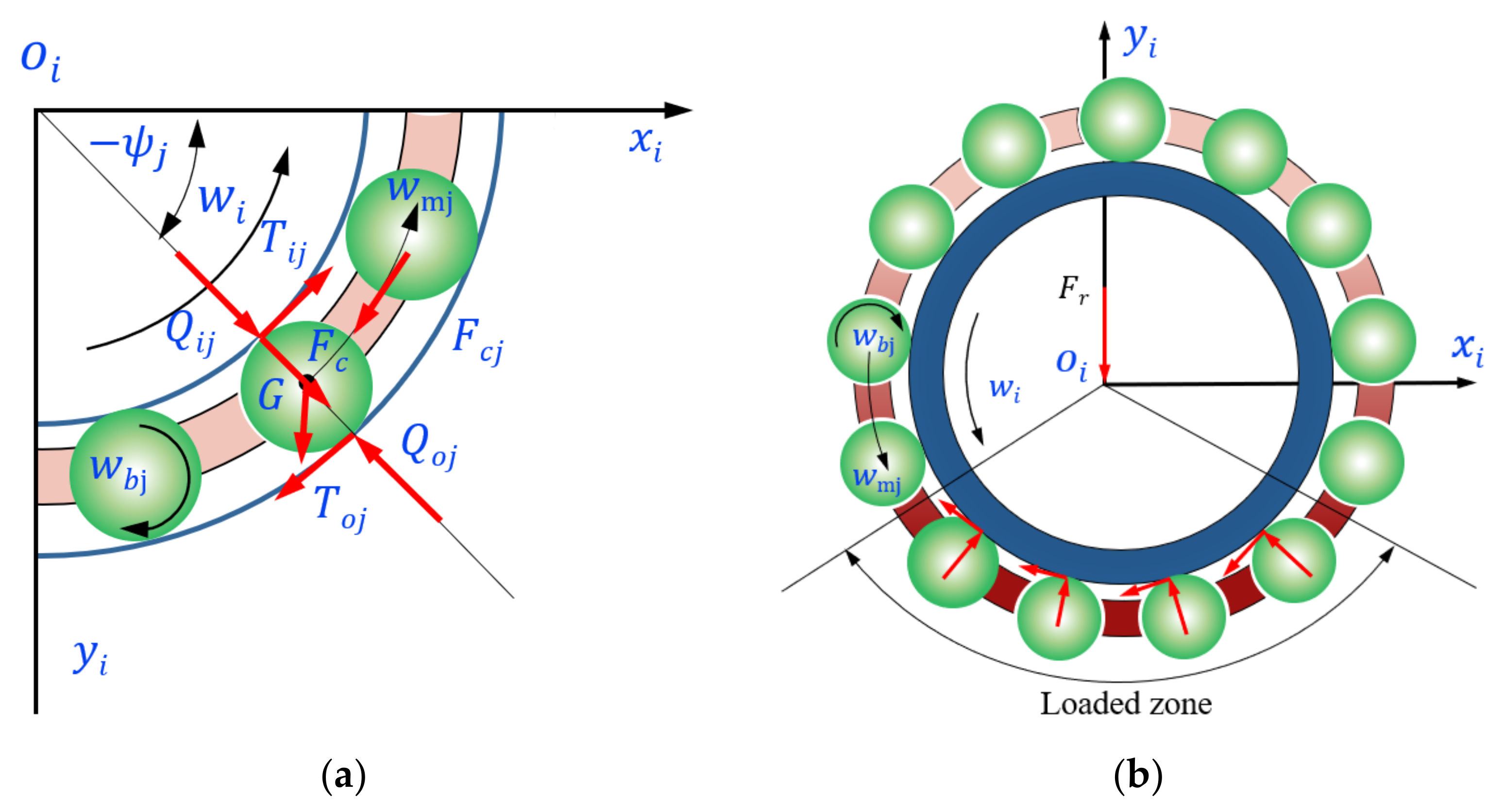
The relationship among the bearing’s internal components is described by Figure 1. The outer ring is fixed, the inner ring rotates at a constant speed, wi, and wc denotes the angle velocity of the cage. The revolution and rotational speed of the jth rolling element are wmj and wbj. Moreover, di is the diameter of the inner groove bottom, while the diameter of the outer groove bottom is do. The pitch diameter of the bearing is dm, which is the mean of di and do. Dw represents the diameter of the ball. ψj is the orbital angle of the jth rolling element, and ψcj is the orbital angle of the cage pocket corresponding to the jth rolling element.
2.1.1. The Force between the Rolling Elements and the Rings
Because of the radial load at operation, the rolling element deforms, which can be determined by the transient coordinates of the inner ring and the rolling element. Under the assumption, the mass center, Obj, of the jth rolling elements is (xbj, ybj) at a certain moment, while the mass center, Oi, of the inner ring is (xi, yi), relative to the bearing center, O.
As shown in Figure 1, the contact deformations between the rolling element and the inner or outer rings can be expressed as Equation (1) or Equation (2), respectively.
where the subscript, ‘+’, indicates that, when the value in the bracket is greater than 0, deformation occurs because of the contact, and when it is less than or equal to 0, it means that no contact or collision occurs, and the deformation is set to 0.
According to the assumption, the contact between the rolling element and the rings can be treated by the Hertz contact theory; therefore, the contact force between the jth rolling element and the inner or outer rings are computed as Equation (3) or Equation (4), respectively:
where represents the deformation coefficient between the rolling element and the inner ring, while represents the coefficient between the rolling element and the outer ring [28].
At this time, the oil film traction force between the rolling element and the inner or outer rings are calculated by the following equations:
where the coefficient of the oil film traction can be calculated as follows:
2.1.2. The Force between the Rolling Elements and the Cage
During bearings operation, the revolution speed of the rolling element in the nonloaded zone is slower than in the loaded zone because of the lack of an inner ring traction force to maintain the speed. Therefore, the rolling elements need to be driven by the cage; thus, the impact force between the rolling element and the cage pocket is negative. Since the inner ring can provide sufficient traction in the loaded zone, the revolution speed of the rolling element increases. At this time, the cage is driven by the rolling element, so the impact force is positive, as shown in Figure 3.
In this paper, the spring model is used to simulate the impact force between the rolling element and the cage pocket [19]. The impact force between the jth rolling element and the corresponding pocket can be written as Equation (10):
where Kc is the deformation coefficient between the rolling element and the cage pocket, which can be obtained according to [30,31].
2.2. Mechanical Equilibrium Equations
As is shown in Figure 4, the inner ring mainly suffers the contact force and traction force of the rolling elements, while the cage is mainly subjected to the impact force of the rolling elements; thus, the quasistatic model of the bearing can be initially established.
The nonlinear equilibrium equations of the force on the rolling element can be written as:
where Fcj is the centrifugal force on the rolling element from [28], and G names the gravity of the rolling element.
The nonlinear equilibrium equations of the inner ring are as follows:
where Fr is the radial load acting on the bearing, and Z is the number of balls.
On the basis of quasistatic model, the dynamic model of the bearing is established considering the bearing dynamic information of each component.
The differential equations of the jth rolling element are given as:
where mb is the mass of the rolling element; rj represents the vector from the center of the bearing to the jth rolling element; and .
The differential equation of the cage is as follow:
where mc is the mass of the cage, and wc represents the rotational speed of the cage.
The differential equations of the inner ring can be written as follows:
where mi is the mass of the inner ring, and xi and yi represent the displacements of the inner ring in the xi direction and the yi direction, respectively.
2.3. Model Solution and Verification
Since the above bearing dynamic model is composed of nonlinear differential equations with strong nonlinearity, with consideration to the convergence and computational efficiencies, the fourth-order Runge–Kutta method was employed to solve the equations. In order to ensure the accuracy of the solution, the Newton–Raphson iteration method was used to solve the quasistatics model first, the results of which were input as the initial values of the differential equations. The specific solution process is shown in Figure 5.
From Figure 5, the bearing structural parameters and the working condition that needed to be solved were input first. Then, the Newton–Raphson iteration method was used to solve the quasistatic equations of the bearing, namely, Equations (11)–(14). If the error is greater than the set target value, the initial value is modified so that the equation can continue to be solved. The result of the solution is taken as the initial value of the dynamics equations, as long as the error is small enough. The fourth-order Runge–Kutta method was used to solve Equations (15)–(20), and the motion state of the bearing of each component at this moment can be obtained. Each calculated time is used to determine whether the prescribed time was reached. If it was not reached, the solution state of each part at this moment is taken as the initial value of the next moment. If it was reached, the simulation analysis results are output.
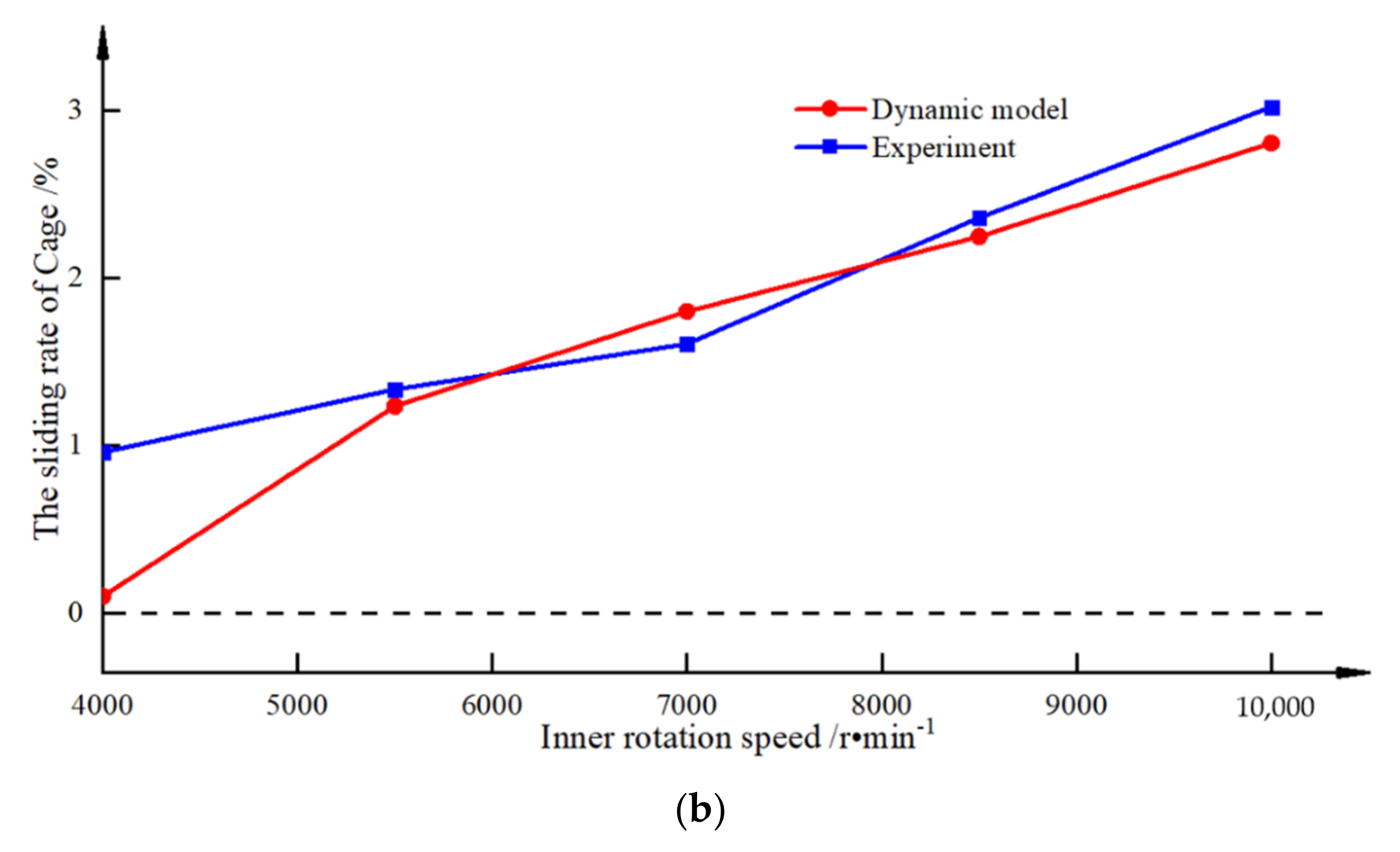
In order to verify the accuracy, the mathematical results of this model were compared with the experimental data [32]. According to the experiment conditions [32], the radial forces were 1500 N and 2100 N, respectively, while the rotational speed of the inner ring was gradually increased, from 4000 r/min to 10,000 r/min. Then, the correctness of the model was verified by the sliding rate of the cage, which can be expressed as:
where wlc represents the theoretical cage speed, wlc = ni·(1 − Dw/dm)/2, and wc is the actual cage speed.
As shown in Figure 6, the sliding rate of the cage increases with the increase in the bearing rotational speed: the greater the radial force, the smaller the sliding rate. The mathematical and the experimental results are basically the same, which proves the correctness of the dynamic model proposed in this paper.
3. Collision Characteristics between the Ball and the Cage
In order to analyze the collision characteristics between the rolling element and the cage pocket, the deep-groove ball bearing was taken as the research object, of which the structural parameters are shown in Table 1. The change process of the impact force between the cage pocket and the rolling element was analyzed, and the influence of the impact force of the adjacent two rolling elements on the cage stability was further discussed.
3.1. Interaction of a Single Ball and the Cage Pocket
In order to analyze the interaction between the balls and the bearing cage, the bearing radial load was set as 1500 N, the inner ring initial speed was 3000 r/min, and the angular acceleration was 100 rad/s2. By solving the dynamics model in the above Section 2, the contact forces between the ball and the inner/outer rings, and the impact force between the ball and the cage pocket can be obtained, respectively.
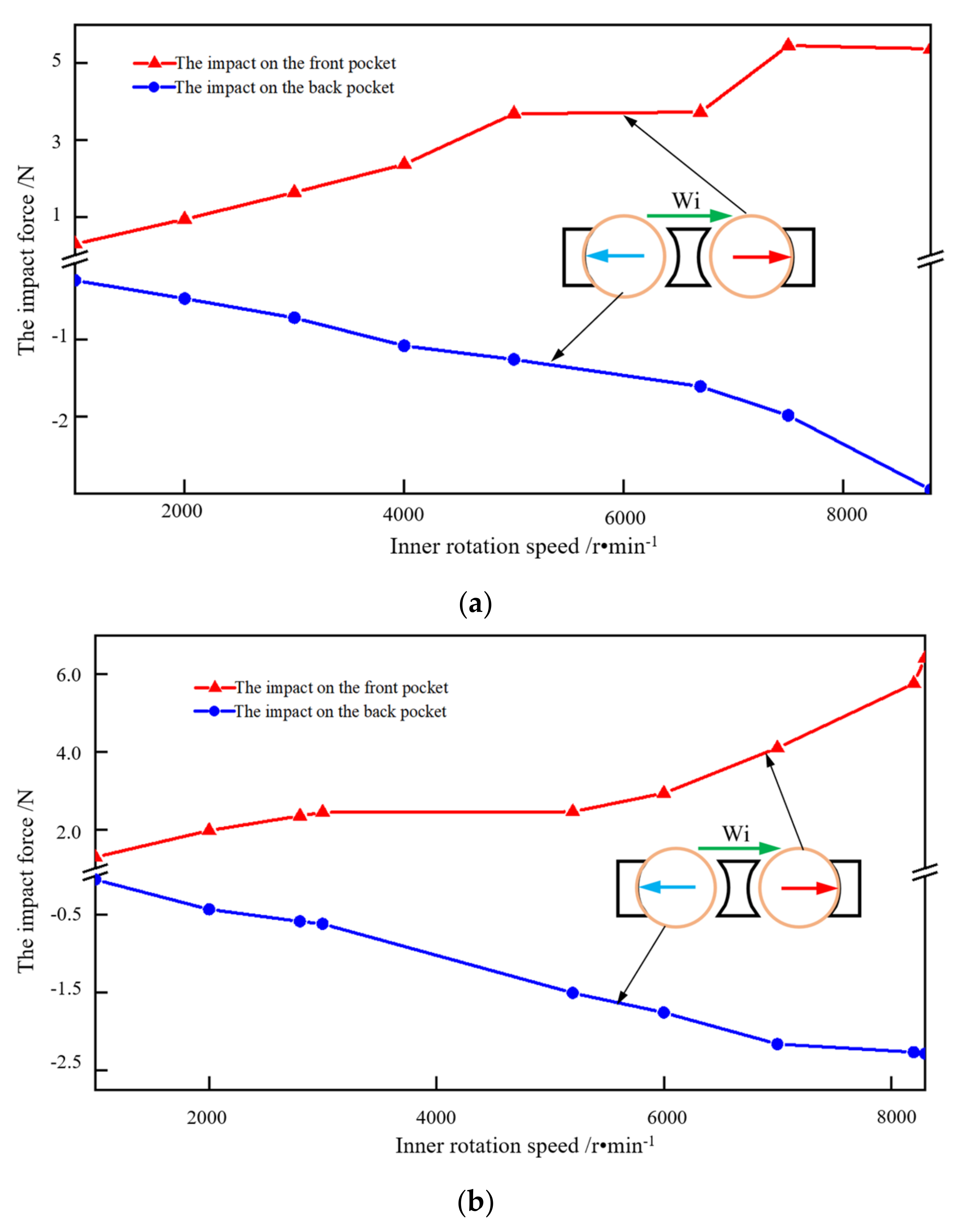
Figure 7 shows the changes in the contact forces of the rolling elements. The blue curve represents the contact force between the ball and the outer ring, the green curve represents the contact force between the ball and the inner ring, and the red curve represents the impact force between the ball and the cage pocket. There are some key points on the collision between the ball and the cage pocket, as seen in Figure 7. The a point is the stable starting point of the collision between the ball and the rear side of the cage pocket; the b point is located at the starting point of the loaded zone; the c point is the ending point of the collision between the ball and the front side of the cage pocket; and the d point is the starting point of the collision between the ball and the front side of the cage pocket. When the ball is rotating in the a–b region, the impact force between the ball and the rear side of the pocket is stable. When the ball is running in the b–c region, the impact force between the ball and the rear side of the pocket is gradually reduced, and is eventually converted from the rear to the front. When the ball is located in the c–d region, the impact force between the ball and the front side of the pocket initially increases, and then decreases. When the ball is in the d–a region, the magnitude of the impact force between the ball and the rear side of the pocket changes significantly.
The above phenomenon is mainly caused by the time-varying relative sliding velocity between the ball and the raceway, as is shown in Figure 8. The impact force between the ball and the rear side of the cage pocket is relatively stable when the ball runs in the a–b zone. This is because, in the nonloaded zone, the contact force between the ball and the inner raceway is slight. In addition, the interaction of the ball and the outer raceway is enhanced because of the centrifugal force. The static outer raceway has a braking effect on the motion of the ball, resulting in an increase in the sliding velocity between the ball and the raceway. At this stage, the orbital speed of the ball is mainly maintained by the cage, which leads to a stable impact force between the rear side of the pocket and the ball. When the ball is situated in the b–c zone, the contact position of the ball and the cage is gradually transferred from the rear side of the pocket to the front, and the impact force decreases as well. This is because the contact force between the ball and the inner ring recovers and gradually increases, which inhibits the sliding between the ball and the raceway to a certain extent, resulting in the increase in the ball orbital speed. Eventually, the impact force between the ball and the rear side of the pocket gradually decreases. When the ball is in the c–d zone, the impact force between the ball and the front of the pocket initially increases, and then decreases. This is because the ball–raceway traction force produced by the contact behavior between the ball and the inner ring inhibits the ball from sliding into the loaded zone, but the traction force is too small to stop the sliding completely. With the increase in the contact force, the ball–raceway traction force increases gradually on the left side of the loaded zone, and the ball orbital speed greatly increases. On the right side of the loaded zone, the orbital speed of the ball increases slightly because the ball–raceway traction force decreases gradually as the contact force decreases, which leads to the change in the impact force between the ball and the front side of the pocket in the loaded zone. When the ball is located in the d–a zone, the impact force between the ball and the rear side of the cage pocket changes greatly. This is because the ball–raceway traction force produced by the contact behavior decreases gradually. Meanwhile, the ball orbital speed has been increasing in the load region, resulting in the increased magnitude of the ball centrifugal force, which further aggravates the sliding of the ball. Finally, the above reasons lead to the collision with the rear side of the pocket, and the magnitude of the impact force is large.
3.2. Impact Force between Two Balls and the Cage
The impact force between two balls and the cage pockets is discussed in this section. As is shown in Figure 9, the a’ point occurs where the collision between the front ball and the cage pocket is converted from the front side to the rear, and the b’ point denotes that the collision between the back ball and the cage pocket has been converted from the front side to the rear. The c’ point appears where the collision between the front ball and the cage pocket is converted from the front side to the rear, and the d’ point means that the interaction has been converted from the front side to the rear. When both of the two balls are running in the a’–b’ zone, the impact force between the front ball and the pocket changes from the rear side to the front, while the back ball maintains the contact with the rear side. The cage will suffer an impact load because of the opposite collision directions. When the two balls are located in the b’–c’ zone, the impact force between the back ball and the pocket changes from the rear side to the front, while the front ball maintains the contact with the front of the pocket. Meanwhile, the impact direction of the two balls is the same, and they push the cage forward together. When the two balls are in the c’–d’ zone, the impact force between the front ball and the pocket changes from the front side to the rear, while the back ball maintains the contact with the rear side of the pocket. Although the impact direction is opposite, the impact force of the two balls acts on the same beam of the pocket, reducing the cage impact load. When the two balls are situated in the d’–a’ section, the impact force between the back ball and the pocket changes from the front side to the rear, while the front ball maintains the contact with the rear side of the pocket. At this time, the direction of the two forces is the same, which is opposite to the cage speed. In summary, when the two balls are located in the a’–b’ zone, a relatively larger collision occurs on the cage because of the opposite impact force acting on the different beams, which may have a significant influence on the cage stability. When the two balls are in the b’–c’ zone, the cage is pushed by the two balls, which can help to maintain the cage stability. When the two balls are running in the c’–d’ zone, the impact force decreases, and the stability of the cage is improved. When the two balls are situated in the d’–a’ zone, the cage is braked by the two balls because of the opposite impact direction. On the basis of the above analysis, this paper focuses on the impact force when the two balls are located in the a’–b’ zone.
4. Influencing Factors Analysis
In order to further investigate the influence of the different factors on the cage stability, on the basis of the analysis in Section 3.2, the deep-groove ball bearing, 6016, in Section 3, was taken as the research object. The peak impact force of the rolling elements in the a’–b’ stage was employed as the evaluation index to evaluate the cage stability. After consulting the relevant design data of this bearing, it was discovered that the basic dynamic capacity of a rolling element–raceway contact is 47.5 kN. The amounts of 5% and 25% of the bearing’s basic dynamic capacity were taken as the light-load and heavy-load operating conditions, respectively, and 1000 r/min, 5000 r/min, and 8000 r/min were taken as the low-speed, medium-speed, and high-speed, respectively. Factors including the rotational speed and radial load, the acceleration and deceleration of the inner ring, and the materials of the rolling element were all analyzed.
4.1. Radial Load and Rotational Speed
In order to analyze the influence of the rotational speed applied to the inner ring and radial load on the impact force between the ball and the cage pocket in the a’–b’ zone, a dynamic simulation of the rolling bearing under different speeds and loads was carried out. Moreover, the change in the peak impact force under the same rotational speed and different radial loads (or under different speeds and the same radial load) was studied while the inner ring rotational acceleration was constant (100 rad/s2).
The change in the peak impact force under the same radial load and different rotating speeds is shown in Figure 10.
Under the same radial load, with the increase in the rotating speed, the peak impact force (the impact forces between the balls and the front side of the pocket, and that of the rear) gradually increases. This is because, with the gradual increase in the rotating speed, the centrifugal force on the ball gradually increases, and the difference in the contact force between the inner ring and the outer ring increases during the ball running in the a’–b’ zone, which results in the increase in the ball sliding. The fluctuation in the ball orbital speed will finally cause the impact force between the ball and the front side of the pocket to increase. At the same time, the contact force between the ball and the outer ring in the unloaded zone increases gradually and is converted into the traction force. Thus, the orbital speed of the ball decreases in the unloaded zone, resulting in the increase in the impact force between the ball and the rear side of the pocket.
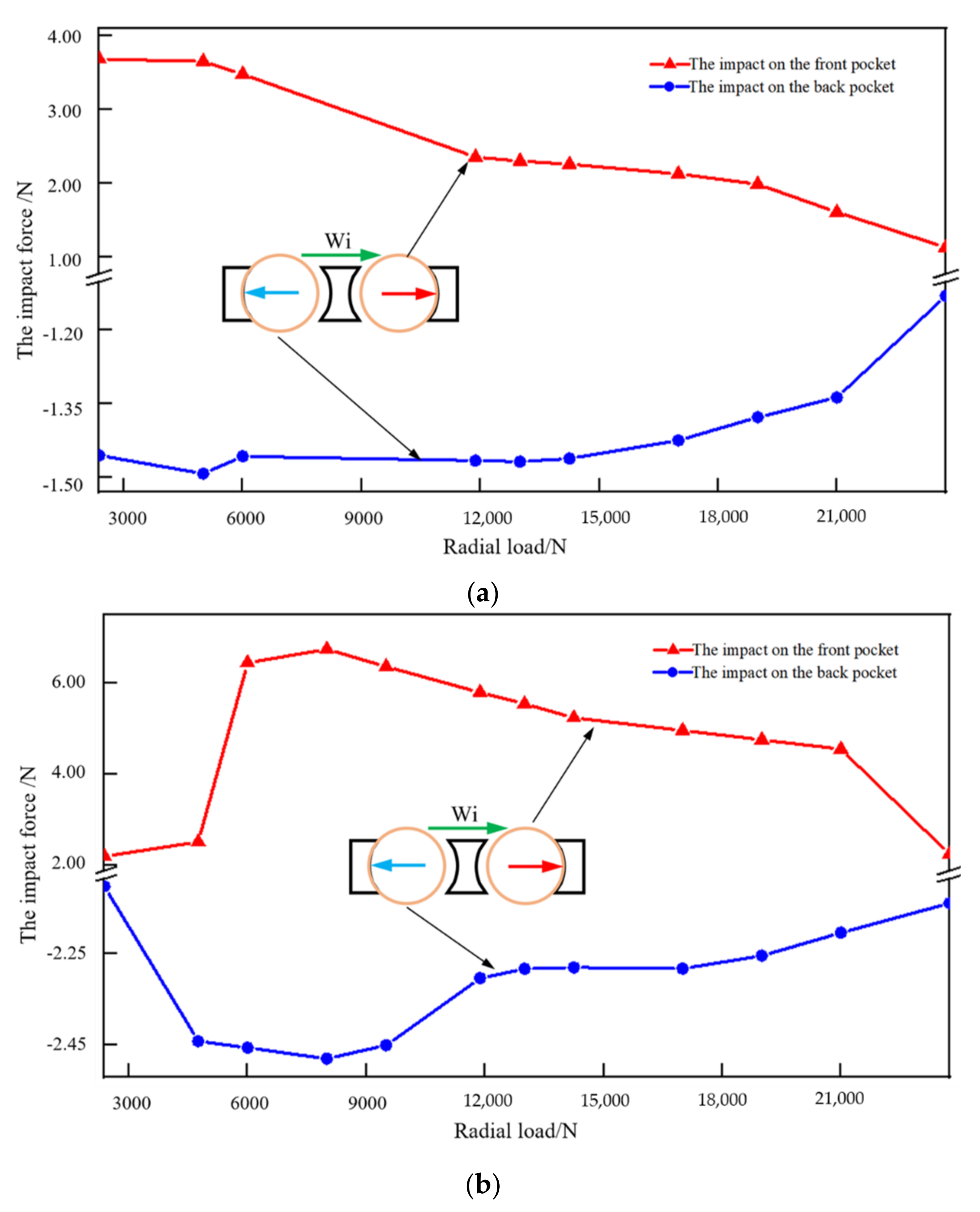
The rule of the peak impact force under the same rotating speed and different radial loads is shown in Figure 11.
Under the condition of the same rotating speed, with the increase in the radial load applied to the inner ring, the impact force increases gradually in the early stage, and then decreases. This is because, when the load increases in the early stage, it is not enough to overcome the sliding of the ball in the loaded zone. As the radial load increases, the traction force increases. Meanwhile, the increase in the radial load means an increase in the loaded zone, and, finally, an increase in the range of the traction force, which leads to the increase in the fluctuations of the ball orbital speed and the increase in the impact force. When the radial load increases to a certain extent, it is enough to overcome the ball sliding. At this time, with the gradual increase in the radial load, the fluctuation of the ball orbital speed decreases, resulting in the decrease in the impact force.
4.2. Inner Ring Speed Acceleration
In order to analyze the influence of the inner ring acceleration on the peak impact force between the ball and the pocket, a dynamic simulation of the rolling bearing under the different acceleration conditions was carried out. Moreover, the influence of the different accelerations on the impact force under a light load, heavy load, and a low rotational speed (1000 r/min) were analyzed. When the rotational speeds of the inner ring and the radial load are constant, the speed acceleration applied to the inner ring gradually increases from 50 rad/s2 to 150 rad/s2. The variation curve of the impact force is shown in Figure 12.
When the rotational speed of the bearing is 1000 r/min, the peak impact force between the ball and the pocket increases with the increase in the inner speed acceleration, regardless of the light load applied to the inner ring or the heavy load. This is because the increases in the inner ring acceleration of the inner ring increases while the contact force between the ball and the inner ring remains unchanged, which aggravates the sliding between the ball and the raceway. In addition, the coefficient of the traction eventually increases, and it increases the fluctuation range of the ball orbital speed, resulting in an increase in the peak impact force. Under a low-speed condition, the peak impact force under the heavy-load condition is larger than under the light-load condition. This is because, with a heavy radial load, the contact force between the ball and the raceway in the loaded zone is enough to overcome the sliding of the ball, while it is not with a light radial load. Moreover, with the inner speed acceleration increasing, the traction force between the ball and the raceway in the heavy-load condition increases more than in the light-load condition, which causes a larger fluctuation range of the ball orbital speed with heavy-load bearing. Therefore, the peak impact force between the ball and the pocket under the heavy load is greater.
4.3. Inner Ring Speed Deceleration
The influence of the inner ring deceleration on the peak impact force under different load and inner ring speed (8000 r/min) was studied. The speed deceleration applied to the inner ring increased gradually from −150 rad/s2 to −50 rad/s2, while the rotational speed and the radial load was constant. The variational curve of the peak impact force is shown in Figure 13.
Contrary to the acceleration state, in the process of inner ring deceleration, the greatest influence on the cage instability appears at the exit of the loaded zone. Because of the effect of deceleration, the impact force between the ball and the rear side of the cage pocket mainly occurs in the loaded zone, while the impact force with the front side of the pocket mainly occurs in the unloaded zone. Therefore, the peak impact force of the adjacent balls on the cage pocket is just opposite, at the loaded zone exit, which may reduce the stability of the cage. The peak impact force gradually decreases with the increase in the deceleration. This is because the deceleration gradually increases, and its value gradually decreases. The reason for the change is the same as that for the speed acceleration change in Section 4.2.
4.4. The Different Ball Material
In order to analyze the influence of the ball material on the peak impact force between the ball and the pocket, a dynamic simulation of the rolling bearing with different roller materials was carried out. Ceramic material and bearing steel were the focuses of the investigation, which are widely used in bearings. The ceramic density was about 3.2 g·cm−3, while the density of the bearing steel was 7.8 g·cm−3.
The effects of different roller materials on the peak impact force were studied under the condition of the same radial load and different rotational speeds (or the same rotational speed and different radial loads). The variation curves of the peak impact forces of the bearings with different ball materials is shown in Figure 14, with the changes in the rotation speeds and radial loads.
It can be seen that the peak impact force of the ceramic ball bearings is smaller than that of the steel ball. This is because the density of ceramic is lower than that of bearing steel. At the same rotational speed, the centrifugal force of the ceramic ball is smaller than that of the steel balls. On the basis of the above analysis, small centrifugal force leads to less contact force between the balls and the bearing raceway, resulting in a lighter sliding of the ceramic ball. Furthermore, the smaller the fluctuations in the ball’s orbital speed, the smaller the peak impact force. Under the condition of the same rotational speed and different loads, the peak impact force of the ceramic ball bearing is almost unchanged. This is because the load has little effect on the peak impact force at the same rotational speed, while the ceramic has little effect on the peak impact force because of its low density.
5. Conclusions
This work established a dynamic model of deep-groove ball bearing, and the factors affecting the cage stability were analyzed from the perspective of the collision between the balls and the pockets. The phenomenon of multiball collision tends to occur when balls near the loaded zone, which may increase the cage instability. Moreover, taking the peak impact force near the loaded zone as the evaluation index, the influences of the radial load, rotational speed, acceleration, deceleration, and material were investigated. The main conclusions are presented as follows:
- From the perspective of the relative sliding velocity between the ball and the raceway, the operation of the ball is divided into four zones. When the balls run in the a’–b’ zone and the c’–d’ zone, the multiball collision effect is obvious. The multiball collision can easily increase the stage instability because of the opposite impact directions of the adjacent two balls when the balls are in the a’–b’ zone;
- Compared to the radial force, the peak impact force is more sensitive to the rotational speed. With the increase in the rotational speed, the sliding between the balls and the raceway becomes more serious, resulting in an increase in the peak impact force;
- The influence of bearing inner ring acceleration and deceleration on the cage instability is the opposite. The peak impact force on the a’–b’ zone can easily cause the cage instability under acceleration, while the deceleration is in the c’–d’ zone because of the direction of the relative sliding velocity.
Author Contributions
Conceptualization, S.M., K.Y. and J.H.; Data curation, S.M. and J.H.; Formal analysis, S.M. and Y.Z.; Funding acquisition, J.H.; Investigation, S.M., X.Z. and K.Y.; Methodology, S.M. and Y.Z.; Project administration, K.Y. and J.H.; Resources, J.H.; Software, S.M.; Supervision, X.Z. and K.Y.; Validation, X.Z. and Y.Z.; Visualization, Y.Z., Y.Z. and J.H.; Writing—original draft, S.M. and K.Y.; Writing—review & editing, K.Y., Y.Z. and J.H. All authors have read and agreed to the published version of the manuscript.
Funding
This research received was founded by the National Outstanding Youth Science Fund Project of the National Science Foundation of China (52022077).
Acknowledgments
The authors would like to thank the National Outstanding Youth Science Fund Project of the National Science Foundation of China (52022077) for the financial support.
Conflicts of Interest
The authors declare no conflict of interest.
References
- Zhang, T.; Chen, X.; Gu, J.; Li, Q. Progress of research on cage stability of high-speed angular contact ball bearings, Hangkong Xuebao/Acta Aeronaut. Astronaut. Sin. 2018, 39, 22026. [Google Scholar] [CrossRef]
- Sathyan, K.; Gopinath, K.; Lee, S.-H.; Hsu, H.-Y. Bearing Retainer Designs and Retainer Instability Failures in Spacecraft Moving Mechanical Systems. Tribol. Trans. 2012, 55, 503–511. [Google Scholar] [CrossRef]
- Liu, D.L.; Jiang, T.; He, Y.H. Discussion on failure problems of aero-bearing. J. Fail. Anal. Prev. 2015, 10, 324–330. [Google Scholar]
- Liu, X.H. Dynamics Analysis Model of High-Speed Rolling Bearings and Dynamic Performance of Cages. Ph.D. Thesis, Dalian University Technology, Dalian, China, 2011. [Google Scholar]
- Kingsbury, E.P. Torque variations in instrument ball bearings. ASLE Trans. 1965, 8, 435–441. [Google Scholar] [CrossRef]
- Kingsbury, E.; Walker, R. Motions of an Unstable Retainer in an Instrument Ball Bearing. J. Tribol. 1994, 116, 202–208. [Google Scholar] [CrossRef]
- Stevens, K.T. Experimental observations on torque variation caused by ball bearing cage instabilities (spin tests). In Proceedings of the Second Space Tribology Workshop, Risley, UK, 15–17 October 1980; Volume 21, pp. 101–111. [Google Scholar]
- Gentle, C.R.; Pasdari, M. Measurement of Cage and Pocket Friction in a Ball Bearing for Use in a Simulation Program. ASLE Trans. 1985, 28, 536–541. [Google Scholar] [CrossRef]
- Walters, C.T. Dynamics of ball bearings. J. Lubr. Technol. 1971, 93, 1–10. [Google Scholar] [CrossRef]
- Kannel, J.W.; Bupara, S.S. A Simplified Model of Cage Motion in Angular Contact Bearings Operating in the EHD Lubrication Regime. J. Lubr. Technol. 1978, 100, 395–403. [Google Scholar] [CrossRef]
- Gupta, P.K. Vibration Lubrication Technology of ball bearings. J. Lubr. Technol. Trans. ASME 1977, 99, 284–289. [Google Scholar] [CrossRef]
- Gupta, P.K. Frictional Instabilities in Ball Bearings. Tribol. Trans. 1988, 31, 258–268. [Google Scholar] [CrossRef]
- Gupta, P.K. On the Frictional Instabilities in a Cylindrical Roller Bearing. Tribol. Trans. 1990, 33, 395–401. [Google Scholar] [CrossRef]
- Gupta, P.K. Modeling of Instabilities Induced by Cage Clearances in Ball Bearings. Tribol. Trans. 1991, 34, 93–99. [Google Scholar] [CrossRef]
- Meeks, C.R.; Ng, K.O. The Dynamics of Ball Separators in Ball-Bearings I: Analysis. ASLE Trans. 1985, 28, 277–287. [Google Scholar] [CrossRef]
- Meeks, C.R. The Dynamics of Ball Separators in Ball Bearings—Part II: Results of Optimization Study. ASLE Trans. 1985, 28, 288–295. [Google Scholar] [CrossRef]
- Houpert, L. Piezoviscous-Rigid Rolling and Sliding Traction Forces, Application: The Rolling Element–Cage Pocket Contact. J. Tribol. 1987, 109, 363–370. [Google Scholar] [CrossRef]
- Houpert, L. CAGEDYN: A Contribution to Roller Bearing Dynamic Calculations Part I: Basic Tribology Concepts. Tribol. Trans. 2009, 53, 1–9. [Google Scholar] [CrossRef]
- Houpert, L. CAGEDYN: A Contribution to Roller Bearing Dynamic Calculations Part II: Description of the Numerical Tool and Its Outputs. Tribol. Trans. 2009, 53, 10–21. [Google Scholar] [CrossRef]
- Houpert, L. CAGEDYN: A Contribution to Roller Bearing Dynamic Calculations. Part III: Experimental Validation. Tribol. Trans. 2010, 53, 848–859. [Google Scholar] [CrossRef]
- Rivera, M.P. Bearing-Cage Frictional Instability—A Mechanical Model. Tribol. Trans. 1991, 34, 117–121. [Google Scholar] [CrossRef]
- Boesiger, E.A.; Donley, A.D.; Loewenthal, S. An Analytical and Experimental Investigation of Ball Bearing Retainer Instabilities. J. Tribol. 1992, 114, 530–538. [Google Scholar] [CrossRef]
- Nogi, T.; Maniwa, K.; Matsuoka, N. A Dynamic Analysis of Cage Instability in Ball Bearings. J. Tribol. 2018, 140, 011101. [Google Scholar] [CrossRef]
- Sakaguchi, T.; Kaoru, U. Dynamic Analysis of Cage Behavior in a Cylindrical Roller Bearing. Spec. Suppl. Ind. Mach. 2004, 71, 8–17. [Google Scholar]
- Sakaguchi, T.; Harada, K. Dynamic Analysis of Cage Behavior in a Tapered Roller Bearing. In Proceedings of the World Tribology Congress III, Washington, DC, USA, 12–16 September 2005; pp. 165–166. [Google Scholar] [CrossRef]
- Weinzapfel, N.; Sadeghi, F. A Discrete Element Approach for Modeling Cage Flexibility in Ball Bearing Dynamics Simulations. J. Tribol. 2009, 131, 021102. [Google Scholar] [CrossRef]
- Ashtekar, A.; Sadeghi, F. A New Approach for Including Cage Flexibility in Dynamic Bearing Models by Using Combined Explicit Finite and Discrete Element Methods. J. Tribol. 2012, 134, 041502. [Google Scholar] [CrossRef]
- Harris, T.A. Rolling Bearing Analysis, 5th ed.; John Wiley and Sons, Inc.: New York, NY, USA, 2006. [Google Scholar]
- Wang, Y.S. Study of Rheological Behavior of Aviation Lubricating Oil and Its Effect on Lubrication Performance. Ph.D. Thesis, Harbin Institute of Technology, Harbin, China, 2006. [Google Scholar]
- Tu, W.; Shao, Y.; Mechefske, C.K. An analytical model to investigate skidding in rolling element bearings during acceleration. J. Mech. Sci. Technol. 2012, 26, 2451–2458. [Google Scholar] [CrossRef]
- Wang, Y. Dynamic Analysis of Angular Contact Ball Bearing-Rotor System during Start up and Shut down. Jixie Gongcheng Xuebao/Chin. J. Mech. Eng. 2018, 54, 9–16. [Google Scholar] [CrossRef]
- Zhang, W.H. Study on the Dynamics Simulation and Semi-Physical Experiment of Cylindrical Roller Bearing. Ph.D. Thesis, Northwestern Polytechnical University, Xi’an, China, 2006. [Google Scholar]
Figure 1.
The mutual positions between the rolling element and the rings: (a) no loading; (b) loading.
Figure 1.
The mutual positions between the rolling element and the rings: (a) no loading; (b) loading.
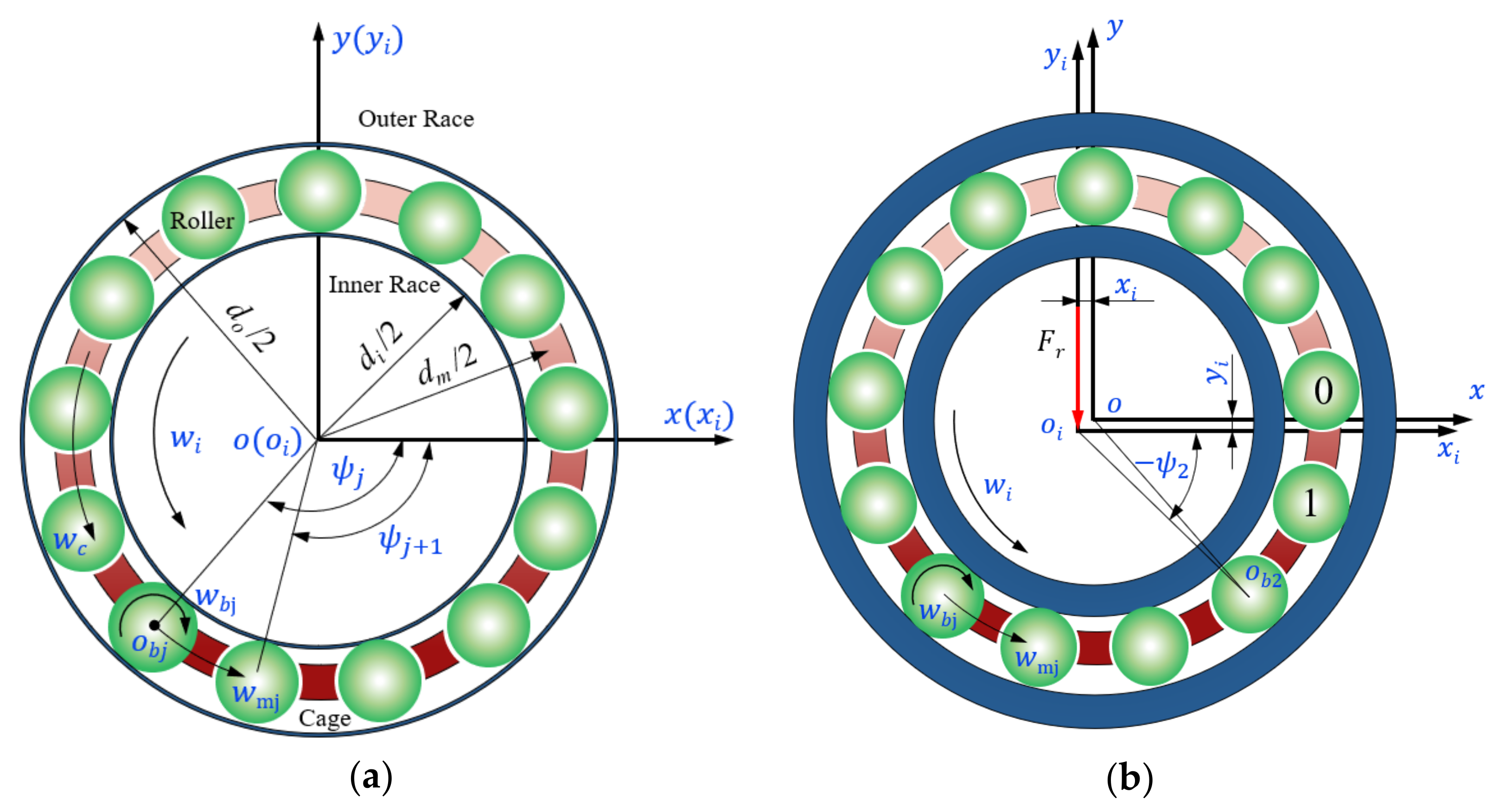
Figure 2.
Velocity analysis between the rolling element and the raceway.
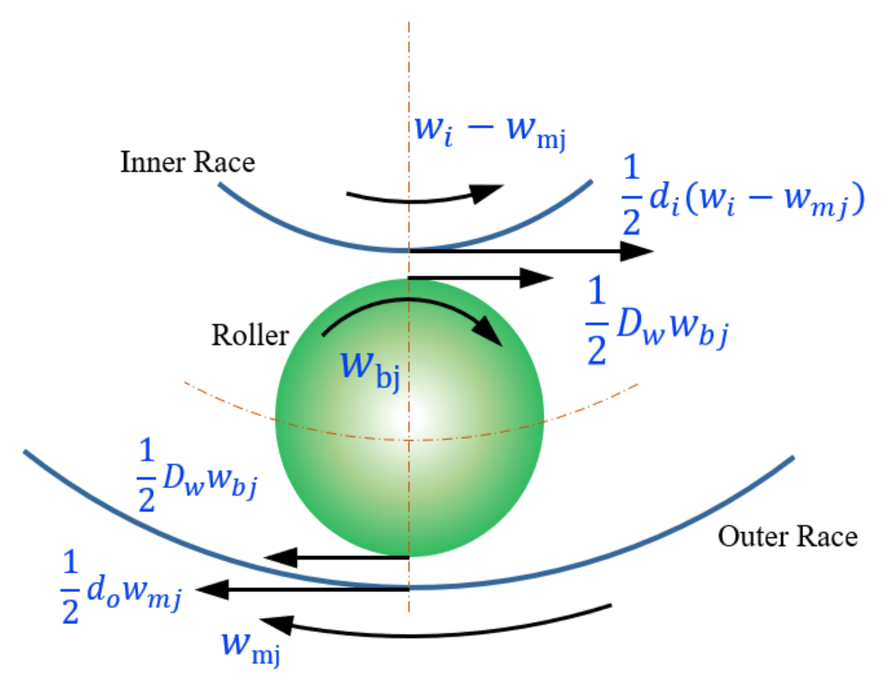
Figure 3.
Interaction between the rolling element and the cage pocket.
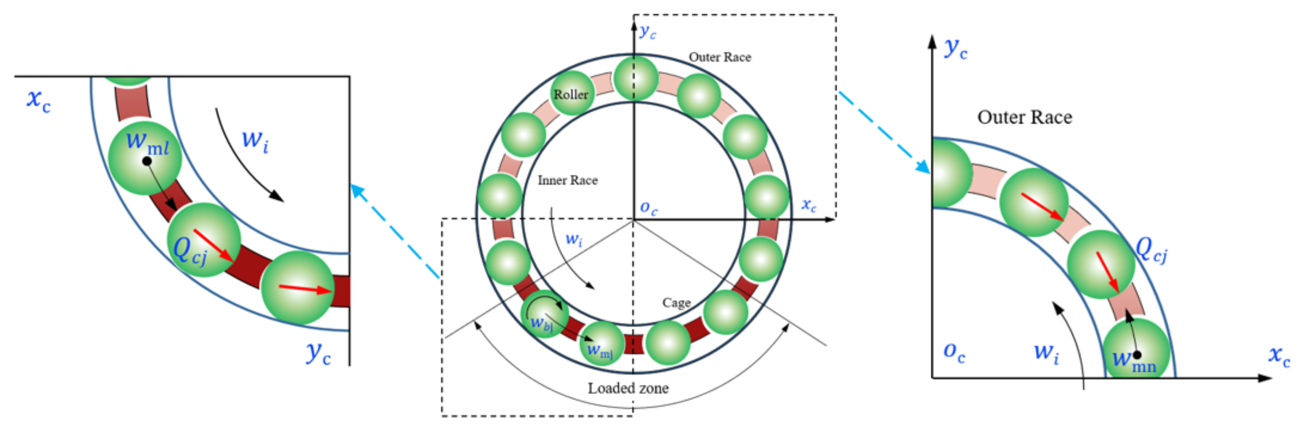
Figure 4.
Force diagram acting on the bearing element and the inner ring: (a) the jth rolling element; (b) the inner ring.
Figure 4.
Force diagram acting on the bearing element and the inner ring: (a) the jth rolling element; (b) the inner ring.

Figure 5.
Flow chart for the solving process.

Figure 6.
Comparison of the mathematical and experimental results: (a) Fr = 1500 N; (b) Fr = 2100 N.
Figure 6.
Comparison of the mathematical and experimental results: (a) Fr = 1500 N; (b) Fr = 2100 N.
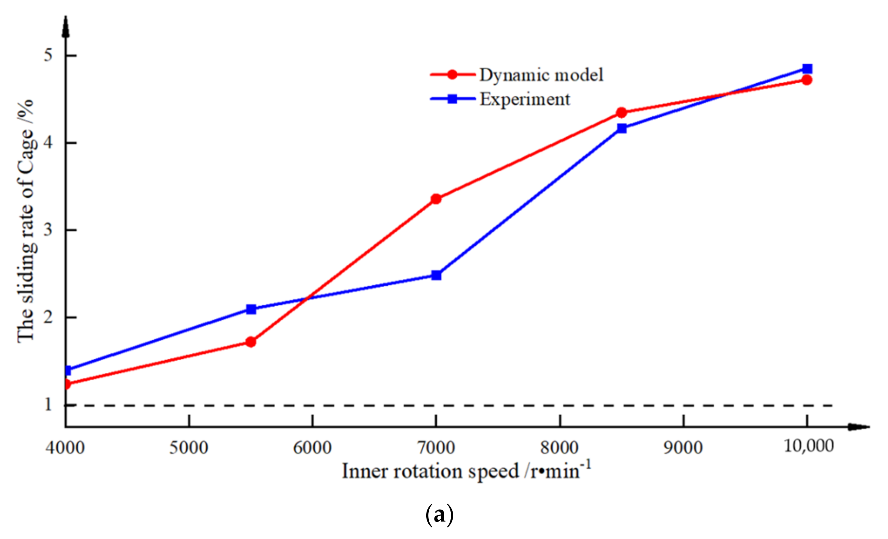

Figure 7.
The trend diagram of the contact force and impact.

Figure 8.
The changes in the ball–raceway contact force and ball sliding.

Figure 9.
An analysis of the impact between the two balls and the cage.

Figure 10.
The effect of the rotational speeds on the impact force: (a) Fr = 2375 N; (b) Fr = 11,875 N.
Figure 10.
The effect of the rotational speeds on the impact force: (a) Fr = 2375 N; (b) Fr = 11,875 N.

Figure 11.
The effect of the radial force on the impact force: (a) n = 5000 r/min; (b) n = 8000 r/min.
Figure 11.
The effect of the radial force on the impact force: (a) n = 5000 r/min; (b) n = 8000 r/min.

Figure 12.
The effect of the speed acceleration on the impact force.

Figure 13.
The effects of the speed deceleration on the impact force.
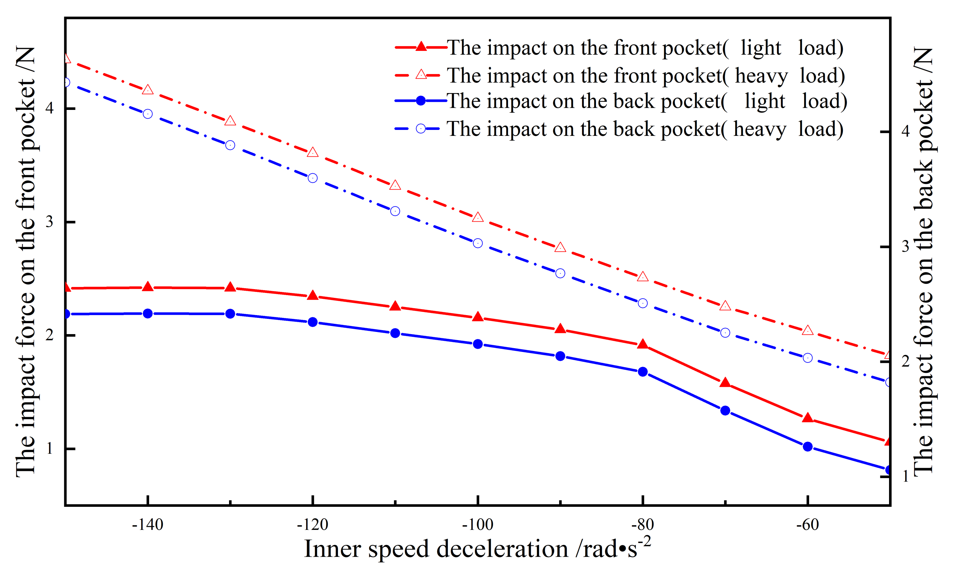
Figure 14.
The effect of the material on the impact force: (a) Fr = 2375 N; (b) n = 5000 N.


Table 1.
Structural parameters of the 6016.
| Name | Value |
|---|---|
| Inner diameter/mm | 80 |
| Outer diameter/mm | 125 |
| Bearing width/mm | 22 |
| Pitch diameter/mm | 102.198 |
| Cage outer diameter/mm | 108.3 |
| Cage inner diameter/mm | 102.448 |
| Cage width/mm | 18.3 |
| Number of balls | 14 |
| Ball diameter/mm | 13.474 |
Publisher’s Note: MDPI stays neutral with regard to jurisdictional claims in published maps and institutional affiliations. |
© 2022 by the authors. Licensee MDPI, Basel, Switzerland. This article is an open access article distributed under the terms and conditions of the Creative Commons Attribution (CC BY) license (https://creativecommons.org/licenses/by/4.0/).
Share and Cite
MDPI and ACS Style
Ma, S.; Zhang, X.; Yan, K.; Zhu, Y.; Hong, J. A Study on Bearing Dynamic Features under the Condition of Multiball–Cage Collision. Lubricants 2022, 10, 9. https://doi.org/10.3390/lubricants10010009
AMA Style
Ma S, Zhang X, Yan K, Zhu Y, Hong J. A Study on Bearing Dynamic Features under the Condition of Multiball–Cage Collision. Lubricants. 2022; 10(1):9. https://doi.org/10.3390/lubricants10010009
Chicago/Turabian StyleMa, Shuaijun, Xiaohong Zhang, Ke Yan, Yongsheng Zhu, and Jun Hong. 2022. "A Study on Bearing Dynamic Features under the Condition of Multiball–Cage Collision" Lubricants 10, no. 1: 9. https://doi.org/10.3390/lubricants10010009
Note that from the first issue of 2016, this journal uses article numbers instead of page numbers. See further details here.