Investigations on the Frictional Hysteresis Effect of Multi-Leaf Journal Foil Bearing: Modeling, Predictions and Validations

1
School of Mechanical Engineering and Automation, Harbin Institute of Technology, Shenzhen 518055, China
2
Shenzhen Key Laboratory of Flexible Printed Electronics Technology, Shenzhen 518055, China
*
Author to whom correspondence should be addressed.
Lubricants 2022, 10(10), 261; https://doi.org/10.3390/lubricants10100261
Submission received: 15 September 2022
/
Revised: 10 October 2022
/
Accepted: 11 October 2022
/
Published: 14 October 2022
(This article belongs to the Special Issue State-of-the-Art of Tribology in China)
Abstract
:Multi-leaf journal foil bearing (MLJFB) is well known for its applications in the air cycle machines (ACMs) of airplanes. However, its frictional energy dissipation mechanism of overlapped foils has not been theoretically studied and is still not clear to researchers. This paper models the frictional sliding/sticking behaviors between adjacent foil leaves based on the tangent gap, applying the penalty method of contact mechanics. Large foil deformations are calculated to simulate the processes of foil assembly and rotor insertion using nonlinear curve beam elements. Predictions of the frictional hysteresis characteristics of MLJFB are obtained, influenced by foil boundary conditions, leaf number, bearing radial clearance and other foil structural parameters, which correlate well with the test results. This study lays solid theoretical foundations for the static and dynamic research of MLJFB.
1. Introduction
Gas foil bearing is the aerodynamic bearing characterized by elastic supports, which possesses superior advantages in the applications of medium- and small-sized high-speed turbomachinery [1]. It has one smooth or multiple top foils to generate lubrication gas film and usually has corresponding underlying foil structures to provide additional stiffness and damping [2].
Multi-leaf journal foil bearing (MLJFB), which is also known as the “leaf-type bearing”, has a number of curve foil leaves with one end installed to the bearing sleeve and the other end overlapped on the next foil leaf, as shown in Figure 1. This type of foil bearing is characterized by the foil structural preload effect and the natural converged gas film clearances. Although MLJFB is famous for applications in the air cycle machines (ACMs) of air planes due to its superior adaption of inertia forces in different directions [1], its static and dynamic performance—especially the Coulomb friction effect—is still not very clear to researchers. Further applications of MLJFB are thus hindered to some extent in other high-speed turbomachinery such as air compressors in blowers and hydrogen fuel cells.
Early researchers have completed valuable work towards the MLJFB, whose potential was first proved in the tests of small gas turbine engines [3,4,5,6]. Analytical models were developed to calculate the foil deformation, and the aeroelastic results demonstrated the inconstant contact states between bearing components. Arakere and Nelson [7] avoided the penetrations between foils and added the constraint of bearing sleeves in their model. Du and Zhu studied the load capacity of MLJFB by including the area contact effect between foil leaves [8]. Li and Du further applied contact mechanics to introduce the inside comprehensive and complex contact constraints [9]. The foil boundary conditions are not the same in the above studies, in which [3,4,5,6,7] deem the fully hinged boundary of the foil end and [8,9] deem the fixed boundaries. Iordanoff et al. [10] developed a model of MLJFB in which the unilateral pivot link of the foil leaf was presented. The authors studied foil contact conditions through the gaps between bearing components. In the above studies, simulations of assembling foil leaves were conducted only under pure geometrical constraints and neglected the effects of foil deformations. Meanwhile, the nonlinear effect of large foil deformation is not considered in the simulation process of rotor insertion. Most of all, the effect of Coulomb friction is not included.
Oh and Rohde [11] applied the tangent friction force to foil elemental nodes of MLJFB and obtained a larger bearing load capacity affected by frictions. However, the bearing sleeve constraint and the hysteresis effect of loading–unloading simulations, as well as the stick/slide contact behaviors, are not included. In addition, bearing load capacities and stiffness coefficients were calculated only at smaller rotor eccentricities, thus not presenting the nonlinear foil structural characteristics.
The MLJFB with back springs was also studied by researchers through theoretical modeling and experiments. Heshmat studied the effects of a step-like back spring on the load capacity and stiffness coefficients of an eight-pad MLJFB [12]. Arakere concluded that the appropriate design of the back spring can increase the bearing load capacity [13]. Geng et al. [14] simulated the assembly process of MLJFB using the bump structure as a back spring. Duan et al. [15] further concluded that the MLJFB with a bump-type back spring exhibits twice the load capacity and stiffness of the bump foil bearing. Du and Zhu et al. conducted comprehensive parametric studies towards the MLJFB with a bump-type back spring [16]. However, the effects of friction and large foil deformation were also not included in these studies [12,13,14,15,16]. Xu et al. studied the influence of friction on the nonlinear foil structural stiffness of a multi-leaf bump foil bearing [17], but the detailed foil structural model and the frictional hysteresis effect were not included.
The dynamic studies of MLJFB are not sufficient compared with the static characteristics. Reddy et al. [18] first studied the dynamic characteristics of MLJFB using the perturbation method. However, the Coulomb damping was not considered. Guo et al. conducted static loading–unloading tests and measurements of rotor dynamic responses towards MLJFB [19]. Obvious hysteresis curves under different foil leaf thicknesses were obtained, and the results indicate a larger enclosed area with a thinner foil leaf. A thicker foil leaf leads to larger rotor displacement under the same static load. However, the influence of rotor–foil frictional contact is not excluded in this study, leading to an evidently larger hysteresis loop area. Schmiedeke et al. conducted experiments of dynamic excitation on the multi-leaf foil bearing with a back spring [20]. Dynamic hysteresis loops were obtained under different frequencies and amplitudes of dynamic loads, which especially show a strong dependence on the load frequency. This indicates the difference in foil structural Coulomb damping between quasi-static and transient results. In addition, the results obtain a four-times-larger foil structural loss factor before rotor liftoff than that at the rotor speed of 60,000 r/min, indicating that the frictions between the rotor and foil leaves under preload conditions have large effects.
Until now, there has been no theoretical study on the frictional hysteresis effect of MLJFB, and most of the studies are conducted towards the bump type foil bearing. Heshmat first simulated the static loading–unloading process through establishing a mechanical model of a bump foil strip based on the beam theory and considering the stick-slide effects under friction [21]. The following studies developed frictional contact models and the corresponding Newton–Raphson iteration algorithms of bump foil bearing to calculate the frictional hysteresis loops under quasi-static conditions [22,23,24,25,26]. The frictional hysteresis loops under dynamic excitations were simulated based on self-developed foil structural models in the studies [27,28] and on Abaqus CAE software in [29]. The dynamic damping of the bump foil structure is calculated, which shows large dependences on excitation frequency, load amplitude and radial clearance.
The frictional hysteresis effect is essential not only in the load carrying performance but also in the vibration and stability analyses of rotor-MLJFB systems. The theoretical research blank of this effect in MLJFB hinders the calculations and predictions of dynamic rotor responses supported by MLJFBs, bearing dynamic coefficients and the foil structural loss factor. In addition, the foil deformation is actually large enough compared with the foil leaf dimensions during the processes of foil assembly and rotor insertion. It is necessary to consider the problem of geometrical nonlinearity during large foil deformations, which is always neglected by previous studies.
In order to handle these problems, this paper established a frictional contact model of a rotor-MLJFB system based on numerical contact mechanics and the nonlinear finite element method in Section 2 [30,31,32]. The behaviors of the tangent stick/slide and normal contact/separation between adjacent foil leaves are modeled, applying the penalty approach and the Lagrange multiplier method, respectively. The nonlinear large deformations of foil leaves are calculated by considering the nonlinear geometrical strains. Thus, the complete analytical model of MLJFB is developed, which includes the calculation algorithms of foil leaves assembly, rotor insertion and the static rotor loading–unloading process. In Section 3, the frictional hysteresis effect influenced by the foil boundary condition, foil leaf number, radial clearance and foil structural parameters is predicted and analyzed. Finally, in Section 4, this effect is experimentally obtained to validate the reasonability of the present model.
The novelty of this study is that the problem of the frictional hysteresis effect in MLJFB is solved for the first time from theoretical perspectives, including calculations of accurate nonlinear large foil deformations. The simulation program is developed without using commercial software due to the fact that the present contact model will be integrated into aero-elastic and rotor dynamic calculations in the future. This study will lay a solid foundation for the dynamic analyses of rotor-MLJFB systems with and without back springs, which can be realized by changing the present quasi-static model to the transient one with foil and rotor masses.
2. Modeling of MLJFB with Coulomb Frictions
The MLJFB is mainly composed of a number of foil leaves and a sleeve that is used to contain and install the foil leaves, as shown in Figure 1. The foil leaf is assembled as one overlapped on another in turn along the circumferential direction, and the foil leaf number is not fixed and is usually 5, 8, 12, etc. The overlapping between foil leaves not only produces elasticity but also leads to the converged gas film clearances. The arrangement of this chapter is: Section 2.1 derives the nonlinear stiffness matrices of the curve beam element, which is applied to model the curve foil leaf. Section 2.2 models the complex contact constraints inside MLJFB. Section 2.3 presents the boundary conditions of foil leaves. Section 2.4 presents the calculation algorithms.
2.1. Nonlinear Curve Beam Element of the Foil Leaf
The finite element method is applied to calculate foil deformations. In the previous study [9], the linear curve beam element is adopted to model the curve foil leaf under fixed boundary conditions. In this paper, hinged boundaries of foil leaves are considered, resulting in large foil deformations compared with the foil leaf dimensions. The nonlinear curve beam model is developed in this study, aiming at handling the problem of geometrical nonlinear large deformations [33,34].
The initial position or configuration of each foil leaf is not fixed. The foil leaf may be tangent with a bearing sleeve inner surface or possess a certain angle θi, as shown in Figure 2a. The radius of the foil leaf is usually larger than that of the rotor in order to obtain the preload effect, and the centers of each foil leaf will locate on the same circle. Each foil leaf is discretized into a number of nonlinear curve beam elements. The arc length of the curve beam element is 0.5 mm in this paper in order to guarantee the calculating accuracy. The cylindrical coordinate and nodal displacements of one nonlinear curve beam element are shown in Figure 2b.
Based on the above definitions, the axial strain Ea in the curve beam element consisting of bending and stretching strains and the geometrical nonlinear strain is formulated as:
where Et is the stretching strain; Eb is the bending strain; En is the geometrical nonlinear strain; v and w denote the tangent and radial displacements, respectively; s denotes the circular coordinate; Rf denotes the radius of each foil leaf.
The vi, wi, Eti and θyi (i = 1, 2) of two elemental nodes are selected as the nodal displacements, and the eight coefficients (A1 ~A4, B1 ~ B4) in Equation (3) can be calculated. Therefore, the shape functions Nv and Nw of v and w can be obtained with these coefficients: v = Nv·ue, w = Nw·ue, where ue is the displacement vector of the curve beam element. The axial strain in Equation (1) can be formulated in the matrix form as:
where Ba is the total strain matrix; and are the linear and nonlinear strain matrices:
where and . The derivations of the nonlinear stiffness matrices of the curve beam elements and are presented in Equations (A1) and (A2) in the Appendix A.
2.2. Contact Constraints Inside MLJFB including Frictions
There are various types of contact constraints inside the MLJFB, such as the frictional area contact between adjacent foil leaves, the contact between the foil sleeve and rigid bearing sleeve and the rotor–foil contact during the processes of rotor insertion and static loading–unloading.
2.2.1. Frictional Foil–Foil Contact
Contact constraints between adjacent foil leaves are described by node–element contact nodes pairs such as A − BC, which is shown in Figure 3. Point A is the slave node of the beam element on the present foil leaf, and BC is a master curve element on the next foil. Point F is the interpolating node on element BC. Because of the possibility of point A sliding on BC, the position of F is not constant and is represented by “s”, which is also a variable besides the nodal displacements.
The normal gap of the contact pair A − BC is formulated as:
where is the gap vector; , F and A are the new positions after foil deformation; is the foil thickness; is the unit normal vector at node F on the deformed surface of BC and is calculated as:
where is the unit normal vector at node B0 before foil deformation; indicates the position of interpolating point F on curve beam element BC; is the angular displacement of node F.
In the previous study [9], the friction effect between overlapped foil layers was not considered, only presenting the normal contact gap and deeming that the present foil leaf slides freely on the next foil leaf without friction. In this study, the friction effect is considered through formulating the tangent gap of the contact nodes pair B − CD as:
where Fref denotes the reference contact node F in this loading step and has the same interpolating coordinate “s” with last loading step, s = s1; is the unit tangent vector at node F and is obtained through rotating by 90 degrees counterclockwise.
In Equations (1) and (2), is calculated based on the initial positions of F0 and A0 and the corresponding displacements:
where wA and vA are the radial and tangential displacements of point A; , , and are the unit normal vectors in the corresponding directions; and are the interpolating functions at position “s” on the curve element BC; is the displacement vector of element BC with a size of 8 × 1.
Based on the normal and tangent contact gaps, the contact energies of a certain contact nodes pair can be derived for the sticking and sliding states. Herein, the Lagrange multiplier and penalty factor are applied to form the contact energies in the normal and tangent directions, respectively, and they have a physical meaning of contact force and tangent contact stiffness [35].
- (1)
- Contact energy formulations for sticking contact nodes pair
The sticking or sliding state of the contact nodes pair A − BC in this loading step is determined based on the last loading step. For instance, if the interpolating position of point F on element BC is “s1” in the last loading step, as shown in Figure 4, the tangent gap in this loading step is calculated based on the reference value “s1” to determine the sticking or sliding state of this contact nodes pair in each iteration.
If the contact nodes pair is in a sticking state, the corresponding formulation of the contact energy is given as:
where and denote the normal and tangent gaps, respectively, which are calculated based on the interpolating point F with position “s1” in this loading step; denotes the Lagrange multiplier, indicating the contact force; denotes the penalty factor, indicating the tangent contact stiffness, and is set as 107 in this study. In order to derive the Newton–Raphson iteration formula for the nonlinear deformation problem, the variation form of is derived as:
where is the general displacement vector of this contact nodes pair, including the nodal displacements of nodes A, B, C and ; is the general contact force vector in the sticking state.
Considering the unchanged position of F or “s1” in the sticking state, the and in Equation (11) are derived as:
where is the displacement vector of the contact nodes pair without . The further differential calculation of is:
where is the tangent matrix of the foil–foil frictional contact nodes pair in the sticking state.
- (2)
- Contact energy formulations for the sliding contact nodes pair
When the contact nodes pair A − BC is the sliding state in this loading step, the contact energy is formulated as:
where denotes the friction coefficient; denotes the sliding direction, which has a value of 1 or −1; is the tangent gap in this loading step considering the position change of the interpolating point F from s1 to s2.
The variation form of the contact energy is derived as:
where is the variation form of , indicating the variation in the sliding distance; is the general contact force vector in the sliding state.
When node A slides on curve beam element BC, the position of interpolating node F satisfies the following equation due to the facts that the normal gap is minimum and the gap vector is perpendicular with the unit tangent vector :
After the differential calculation of Equation (17), the relationship between and can be obtained:
where is the calculated matrix relating with ds; the “s” is calculated with s2, which denotes the position of F in this loading step. Therefore, the in Equation (16) is obtained.
The variation of the normal gap under the sliding state has different formulations from those under the stick state because the position of F or “s” is also a variable in this condition. It is worth noting that the “s” is calculated with s2 for the sliding condition.
The further differential calculation of is derived as:
where is the tangent matrix of the frictional contact nodes pair in the sliding state.
2.2.2. Foil-Bearing Sleeve Contact
The contact between the foil leaf and bearing sleeve is studied through a random nodal D on the foil, as shown in Figure 3a. Assuming D1 is the point on the inner surface of the bearing sleeve that is to come into contact with D, which is the position of D0 after foil deformation, the gap of the foil-bearing sleeve contact pair is formulated as:
where is the radius of the bearing sleeve inner surface; wD and vD are the radial and tangential displacements of node D; and are the unit normal radial and tangential vectors on node D0.
2.2.3. Rotor–Foil Contact
When studying the contact type between the rigid rotor and each foil leaf in Figure 3a, E is a random nodal point on the foil, and E1 is the point on the rotor surface that will contact with E. The gap of the rotor–foil contact pair is:
where and are radial and tangential displacements of node E; and are the unit normal radial and tangential vectors; Rr is the radius of the rotor surface.
The derivations of contact energies, as well as the contact force vectors and tangent matrices of the foil–sleeve and rotor–foil contact constraints, can be found in the previous study [9].
2.3. Boundary Conditions of the Elastic Foil Leaves
The boundary conditions of each foil leaf have always been ignored by researchers when investigating the MLJFB. Figure 5 describes three different types of boundary conditions that can cover almost all the application circumstances.
The first is the fixed boundary condition under which the translational and rotational displacements of each foil end are all constrained. The second is the hinged-fixed boundary condition. The foil leaf can freely rotate within a certain range, which is described as stage one. If the foil leaf is rotating away from the bearing sleeve, there exists a threshold when two corner nodes of the foil end come into contact with the bearing sleeve, and the boundary conditions will transfer from the hinged boundary to the fixed boundary. The threshold of the rotating angle θrb can be calculated by solving the following equations:
where ws is the groove width on the bearing sleeve; lf1 and wf2 are the length and width of the bending corner. If the threshold is reached, the constraint of rotating away from the bearing sleeve is activated by adding the rotation contact energy:
The third is the totally hinged boundary. Each foil leaf can rotate freely in both directions during the processes of foil assembly and rotor insertion.
2.4. Iteration Formula and Calculation Algorithms
2.4.1. Iteration Formula
Through the modeling processes, it is shown that the deformation of the overlapped foil leaves of the MLJFB is significantly nonlinear, not only due to the geometrical nonlinear deformation but also because of the nonlinear contact constraints including the frictions. Therefore, the Newton–Raphson iteration method is applied to solve this nonlinear deformation problem. The variation form of the total potential energy can be formulated as:
in which is the strain energy of the ith curve beam element and is the total number of curve beam elements; , and are the frictional contact energy between adjacent foil leaves, the contact energy between the foil leaves and bearing sleeve and the contact energy between the rotor and foil leaves of the ith contact nodes pairs, respectively; , and are the total contact pair numbers of the corresponding contact types; is the contact energy that is active when the foil leaf has a relatively large rotation away from the bearing sleeve; Q, GU and KU are the general displacement vector, contact force vector and tangent matrix, respectively, which can be obtained by assembling the corresponding vectors and matrices of each contact nodes pair.
2.4.2. Calculation Algorithms
The schematics of foil leaf assembly, rotor insertion and static rotor loading–unloading are shown in Figure 6, and the corresponding calculation algorithms are given in Figure 7a,b, respectively. During the foil assembly simulation, the rotor–foil contact constraint is not activated. Based on the initial positions of the foil leaves, an overlapped new configuration is obtained after the foil assembly process. Due to the obviously smaller inscribed circle diameter of the foil structures compared with the rotor, the rotor insertion simulation is conducted by gradually increasing the rotor diameter. The static rotor loading–unloading process is conducted after rotor insertion by increasing or decreasing the rotor eccentricities ey in the y direction. The bearing reaction force Fy in the y direction is calculated based on Equation (28).
where is the contact force of the ith contact node; Ncr is the number of contact nodes; is the position vector of the contact node on a certain foil leaf.
3. Results and Discussions
This section presents the calculation results and detailed discussions based on the model developed in Section 2. Section 3.1 studies the influences of the nonlinearity of large foil deformations. Section 3.2 includes the frictions and studies the hysteresis characteristics of overlapped foil structures. The calculation parameters applied in this chapter are given in Table 1, in which the values in bold are selected as the baseline parameters.
3.1. Influences of Nonlinear Large Foil Deformation in MLJFB
In Section 2.1, the nonlinear geometrical strain is included in Equation (1) to solve the problem of large foil deformations. Figure 8a,b show the assembly results of the overlapped foil leaves modeled by linear and nonlinear curve beam elements, respectively. Each subfigure also presents the results under different installation angles θi of each foil leaf, which are defined in Figure 2a. In this section, the parameters of the studied MLJFB are selected as the bold values in Table 1, except the foil leaf radius Rf equals 1.5 × Rr and μ is 0.
When the linear element is applied, it first shows that the configurations of overlapped foil leaves after foil assembly are obviously different under different values of θi (different initial configurations of foil leaves). When θi is 0°, the inscribed circle radius Rfa is 16.2 mm, which is much larger than the result when θi is 15°. The results of the foil arc length L1 after foil assembly also exhibit a difference; they are both larger than the initial foil length of 23.4 mm before foil assembly. Secondly, the contact forces between adjacent foil leaves are also not consistent under different θi, values, showing the larger force value when θi is 0°.
In comparison, when the effect of nonlinear large foil deformation is considered, the configurations of overlapped foil leaves, the foil length and the contact force between the foil leaves all show great consistency after foil assembly.
Figure 8c,d show that the gap distributions between the rotor and foil leaf as well as the static loading curves are very close under different values of θi with nonlinear curve beam elements, but the results exhibit obvious difference when calculated with linear elements.
The results in this section indicate that the linear curve beam element can lead to prediction errors of MLJFB, and the consideration of the geometrical nonlinearity of large foil deformation is very necessary.
3.2. Frictional Hysteresis Characteristics of MLJFB
This section investigates the frictional hysteresis characteristics of MLJFB, influenced by the friction coefficient, foil boundary condition, leaf number, bearing radial clearance and foil structural parameters through static loading–unloading simulations. This hysteresis effect results from the frictions between adjacent foil leaves, which is very important, as it influences both the bearing stiffness and Coulomb damping. The baseline bearing parameters are selected as the bold values in Table 1.
3.2.1. Influence of the Friction Coefficient
Firstly, in order to obtain a better understanding of the analysis in the following sections, Figure 9a illustrates the numbering of foil leaves (eight-leaf bearing as an example) and elemental nodes. Figure 9b shows the contact states of the sliding directions between adjacent foil leaves: “sliding apart” and “sliding close”.
Figure 10a presents the results of static loading–unloading curves under different friction coefficients μ between adjacent foil leaves. For different cases, the static load is imposed and increased gradually until the same value of 45 N is reached, and then the unloading process starts. It shows that the larger μ leads to the larger loop area enclosed by the loading–unloading curve, indicating a better Coulomb damping performance, and the foil structural stiffness, i.e., the slope of the loading curve, is also higher.
Figure 10b–d show the contact states between foil leaves during loading and unloading processes. The nodes on the foil leaves 3, 4, 5 and 6 tend to possess the contact states of “sliding apart” during the loading process, and the nodes on the foil leaves 1, 2, 7 and 8 tend to possess the contact states of “sliding close”. During the unloading process, the above sliding directions tend to change oppositely. These sliding directions are determined by nodal tangent displacements, which also correlate closely with radial foil deflections due to the coupling effect between the nodal displacements of the curve beam element. Therefore, the friction forces imposed on each foil leaf tend to hinder the radial foil deflections, which is the cause of the frictional damping effect.
Also worth noting is the influence of the friction coefficient μ on the stick states. Firstly, the larger friction coefficient leads to more sticking contact nodes during both the loading and unloading processes. Secondly, the sticking state tends to happen at the beginning of the unloading process, and an increased μ tends to stick the contact nodes at more unloading steps. The above effects are responsible for the larger area enclosed by the loading–unloading curves.
3.2.2. Influence of Foil Leaf Boundary Conditions
Figure 11a shows the influence of the groove width on the bearing sleeve ws on the foil boundary condition. If ws equals the width value of the foil end wf2, each foil leaf has a fixed boundary condition. Otherwise, the foil leaf possesses a hinged–fixed boundary condition.
Figure 11b presents the results of static loading–unloading simulations under different values of ws. It shows that the fixed boundary of foil leaves results in the smallest area enclosed by the loading–unloading curve. When the ws is increased to 3.05 mm to allow for a slightly wider free rotation range of each foil leaf, the hysteresis area obviously increases. It continues to increase if ws is further increased to 3.1 mm, but it has little change when ws is further enlarged to 3.2 mm.
The reason for above results can be analyzed by Figure 12, which illustrates the contact forces and contact states between foil leaves and also the contact forces between the rotor and foil leaves. For the fixed boundary condition, the foil leaves have no elemental nodes contact with the rotor at the beginning of the loading process, and the contact force is zero. The stick states at the small rotor eccentricities in Figure 12c also prove this point, which also indicates the larger radius of the inscribed circle of the assembled foil leaves and that there is no rotor preload effect. The foil structural stiffness, i.e., the slope of the loading curve, is thus lower at the beginning of the loading process. The contact forces between foil leaves are also smaller in this period because of the fact that the fixed constraint of the foil end results in insufficient interactions between adjacent foil leaves. The fixed boundary leads to a less elastic foil structure, and each foil leaf cannot slide or deflect sufficiently, resulting in more sticking nodes during the loading–unloading process. The size of the hysteresis area is thus limited.
When ws gradually increases, the foil structure becomes less compact, and the radius of the inscribed circle before the rotor insertion becomes smaller. The rotor tends to come into contact with the foil leaves, and its preload effect is excited, thus resulting in a larger foil structural stiffness at the beginning of the load process. The contact forces between the foil leaves are also increased. The contact nodes between the foil leaves tend to slide more freely, and the hysteresis area becomes larger.
Even though a much larger slot width ws results in a smaller inscribed circle after foil assembly, the MLJFB will have the same configurations after the rotor insertion, as well as the assembly preload between the foil leaves and between the rotor and foils. Therefore, the frictional hysteresis curves almost remain unchanged.
3.2.3. Influence of the Foil Leaf Number
This part studies the influence of the foil leaf number on the static loading–unloading results of MLJFB. The other parameters are selected as the bold values in Table 1. Figure 13a illustrates the configurations of foil leaves before the overlapping assembly. Figure 13b shows that the MLJFB with more foil leaves possesses a larger foil structural stiffness, especially at small rotor eccentricities. The bearing (D × L = 35 × 35 mm2) with five foil leaves shows obvious nonlinear stiffness values during the loading process. The foil structural stiffness is lower at small rotor eccentricities due to the larger supporting span, but the main supporting foil leaf comes into contact with the bearing sleeve under a relatively large static load, thus having a rigid support. This evident nonlinear effect hinders the increment of the frictional hysteresis area Sh, which is the smallest for the five-leaf bearing. On the other hand, the Sh of the 12-leaf foil structure is also not the largest because the maximum rotor displacement and foil deformation are limited. In comparison, the eight-leaf foil structure dissipates the most energy during the loading–unloading process.
The frictional hysteresis area Sh not only depends on the general foil structural stiffness, i.e., the rotor displacement, but it is also affected by the normal contact forces and contact states shown in Figure 14, which can further explain above static loading–unloading results.
It shows that the contact forces are generally small when Nf is 5, but there is an abrupt increment of the contact force at the end of loading process, indicating the contact of foil leaf 2 with the rigid bearing sleeve. In comparison, the contact forces are generally larger throughout the loading–unloading process when Nf is 12, especially between foil leaves. Even though foil leaves 4, 5, 6 and 7 play the main supporting roles, the contact forces on other foils also cannot be ignored. These results indicate the pronounced preload effects of assembled foil leaves and rotor insertion with more foil leaves, which benefit the frictional hysteresis effect.
For the five-leaf MLJFB, the node on the free end of foil leaf 2, which has the largest contact forces, experiences the transition of contact states from sliding to sticking and back to sliding again in the opposite direction. For the 12-leaf MLJFB, the unloading steps of the sticking state are fewer in number. This is because the contact node is easier to slide between overlapped foil leaves with a larger leaf number. The turn corner of the unloading curve from the larger slope section to the smaller slope section appears relatively earlier in this condition and hinders the increment of the frictional hysteresis area.
3.2.4. Influence of Bearing Radial Clearance
The radial clearance is significant for gas bearings, which, for MLJFB, is defined as the value Cini deducting double foil thicknesses from the clearance between the bearing sleeve and rotor, as shown in Figure 15a. Its influences on static loading–unloading results are shown in Figure 15b. For a small clearance value of 50 μm, the foil structural stiffness is the largest in the beginning of the loading process, leading to the smallest rotor eccentricity at the same static load of 45 N. In this condition, the calculated hysteresis area Sh is the minimum among the three cases. With the increase in Cini, the maximum rotor eccentricity increases, and so does the value of Sh. However, the frictional energy dissipation ability is hindered at relatively large static bearing loads, e.g., 100 N under a large radial clearance, because the increment ΔSh is the smallest due to the displacement limitation of the bearing sleeve.
Figure 16a shows that the small radial clearance 50 μm increases both the contact forces between the foil leaf and the rotor and those between the adjacent foils, resulting in a more compact foil structure. The nodes on the second and sixth foil leaves tend to stick rather than slide, as depicted in Figure 16c. The nodes on the third foil leaf start to slide only at larger static loads, and those on the fourth and fifth foil leaves tend the maintain the sticking state for more steps after transiting to the unloading processes. For the larger radial clearance condition, Figure 16b shows that the assembly contact forces at zero rotor eccentricity are evidently lower. The foil structure is generally more elastic. The third and fourth foil leaves obviously play the main role of supporting, which is different from the small clearance condition. The nodes of different foil leaves tend to slide more easily, but the sticking effect at the beginning of the unloading process is not outstanding.
3.2.5. Influence of Foil Leaf Structural Parameters
This subsection mainly investigates the influence of foil leaf structural parameters, including the initial foil leaf radius Rf, the foil leaf thickness tf and the foil overlapping ratio λ, on the frictional hysteresis characteristics of MLJFB.
- (1)
- Initial foil leaf radius
The initial foil leaf radius Rf refers to the radius of the curve foil before its overlapping assembly, as shown in Figure 17a. Different values of Rf result in different foil structural characteristics. In Figure 17b, a higher foil structural stiffness is calculated under larger values of Rf, especially at the beginning of the loading process. However, the variation in the hysteresis area is not monotonous with the increase in Rf. The Sh increases from 0.67 to 0.97 mJ when Rf increases from 1.2 to 1.8 times of Rr but decreases to 0.73 mJ if Rf is further enlarged to 2.1 times of Rr, thus indicating that the too-large Rf is not beneficial for the Coulomb damping performance of MLJFB.
The reason for the above results can be analyzed with the help of the contact forces and states in Figure 18. Firstly, the obviously larger contact forces on each foil leaf in Figure 18b indicate that the large value of Rf increases the preload effects of the rotor insertion and foil assembly. This compact foil structure increases the bearing stiffness and the effect of friction force. However, the decrease in Sh when Rf is 2.1 times of Rr is not just due to the large foil stiffness and small rotor eccentricity, which are not evidently changed compared with the 1.8 times of Rr. Additionally, the contact nodes between foil leaves tend to maintain the sticking state in loading and unloading processes under significant larger contact forces, thus demonstrating insufficient sliding motions in a complete cycle.
- (2)
- Foil leaf thickness
The influence of foil thickness tf is investigated in this subsection with maintained bearing radial clearance, as shown in Figure 19a. The loading–unloading simulation results show that the medium value of tf equaling 150 μm calculates the largest value of Sh. The foil leaf with a 0.1 mm thickness results in the lowest frictional dissipated energy. For the studied eight-leaf MLJFB with a size of 35 × 35 mm2, a tf as thin as 0.1 mm leads to the low foil structural stiffness in most ranges of smaller rotor eccentricities, and the hysteresis area is very small. The bearing stiffness is greatly improved by the thick foil leaf that is 0.2 mm in thickness, and the maximum rotor eccentricity is significantly reduced to 20 μm at the same static load of 45 N. The value of Sh is very limited.
When tf is 0.1 mm, the foil structural stiffness increases significantly at a large rotor eccentricity because the foil leaves in the loading direction have come into contact with the bearing sleeve, which provides rigid supports. The abrupt contact force between the rotor and the fourth foil leaf at the end of the loading process can explain this effect further, as shown in Figure 20a. Due to the soft foil structure under thin foil leaves, the preload effect of foil assembly and rotor insertion is weak. The foil nodes tend to slide at most simulation steps, as shown in Figure 20c. A tf as thick as 0.2 mm evidently increases the foil structural stiffness as well as the preload effects of rotor insertion and foil assembly, as illustrated by the large contact forces on each foil leaf throughout the loading–unloading process in Figure 20b. The overlapped foil structure is very stiff in this condition, and the foil nodes tend to stick. The rotor eccentricity, i.e., the foil sliding distance, is extremely limited. Therefore, the hysteresis area is not large.
- (3)
- Foil overlapping ratio
The foil overlapping ratio λ represents the arc length of each foil leaf, which is illustrated in Figure 21a, and its calculation formula is also given. λ equaling 0.5 means that the foil length is twice the arch length between the adjacent installation grooves on the bearing sleeve inner surface. Figure 21b shows the calculation results of the static loading–unloading process under three values of λ. Firstly, the frictional hysteresis area Sh is almost the same when λ is 0.35 and 0.4, which is obviously larger than the result of “λ = 0.45”. This indicates that a too-long foil leaf is not beneficial for increasing the Coulomb damping. Secondly, the foil structural stiffness or curve slope is lower under the smaller value of λ, especially at the beginning of the loading process, i.e., small and medium rotor eccentricities. For instance, when λ is 0.35, the stiffness first maintains lower values and then experiences an evident enhancement at larger rotor eccentricities and shows nonlinear characteristics. The maximum rotor eccentricity is also larger.
The reasons for above results can be analyzed with the results of contact forces and contact states in Figure 22 under different values of λ. Similar to the effect of a larger foil radius Rf, a longer foil leaf, i.e., a large value of λ, tends to make the foil structure more compact and stiff after rotor insertion, as the contact forces are obviously larger over the loading–unloading process, as shown in Figure 22b. When λ is 0.45, the node in the middle of each foil leaf is observed in the contact state after the rotor insertion besides the node on the foil-free end. This effect reduces the supporting span of each foil and increases the foil stiffness. Meanwhile, the larger value of λ also tends to hinder the sliding motion between foil leaves and stick the nodes on different foil leaves during both the loading and unloading processes, as shown Figure 22d.
Only the foil free end is in the contact state at the beginning of the loading process with a short foil leaf (λ is 0.35), and the foil stiffness is lower. The other foil nodes come into contact at larger static loads, and the foil stiffness is gradually increased. More nodes are in the sliding state. In this condition, the preload effect of the foil assembly and rotor insertion is weak, and so is the frictional damping ability.
4. Experiments
This section conducts experimental studies of MLJFB to validate the developed foil structural model considering frictions and nonlinear large foil deformations.
The simulated configurations of overlapped foil leaves (foil assembly) before rotor insertion are compared with different MLJFB test pieces, as shown in Figure 23. The foil leaf is manufactured by cold rolling. The baseline parameters are also selected as the values in bold in Table 1, except the radius of the bearing sleeve inner surface is 18.05 mm, and the friction coefficient is 0.1.
The comparison results demonstrate that the simulated foil structural configurations after foil assembly are in good agreement with the corresponding MLJFB test pieces under different conditions. Firstly, the simulations and the practical foil assembly results both indicate a smaller radius of the inscribed circle Rfa of the 8-leaf MLJFB compared with the 5-leaf and 12-leaf bearings, as shown in Figure 23a. Secondly, the Rfa is smaller with longer foil leaves, i.e., a larger value of λ, for both the simulations and test pieces, as shown in Figure 23b. Thirdly, it shows that the influence of the initial foil leaf radius Rf on Rfa seems to not be evident when comparing the bearing configuration under an Rf of 1.2 × Rr with the results under an Rf of 1.8 × Rr.
The test rig for the static loading–unloading tests is set up in this study, as shown in Figure 24. The test bearing is assembled to the non-rotating journal and is loaded by a cylinder through the force transducer. Two vertically distributed eddy current displacement sensors are applied to measure the relative rotor displacements with respect to the bearing sleeve. Firstly, the displacement values are read as and without foil leaves and rotor contact with the bearing sleeve. Then, the displacement values and can be calculated with the concentric rotor using Equation (29) [31]. Therefore, the displacement variations are calculated as Δd1 and Δd2, given that the absolute values read by the sensors are and . At last, the rotor displacements in the y directions can be calculated as dy.
This is different from the simulation results in Section 3. It is necessary to consider the friction force between rotor and foil leaves in order to compare it with the test results when calculating the bearing reaction force Fy in Equation (30):
where is the unit vector of the friction force between the rotor and foil leaf depending on the loading directions, as shown in Figure 24. The friction coefficients between the rotor and foil leaf and between the adjacent foil leaves are assumed to be the same.
The loading process is continued until the static load reaches about 55 N, and then the unloading process follows. In the tests, the real static load imposed on the bearing is less than the value read by the load cell, considering a bearing mass of about 0.4 kg. Figure 25 shows the comparisons between the simulations and the test results of the loading–unloading curves, which demonstrate good agreement. Firstly, the simulations and test results both show an overall higher foil structural stiffness, i.e., a smaller maximum rotor displacement under larger values of the leaf number Nf, initial foil radius Rf, foil overlapping ratio λ and foil thickness tf. Secondly, the shapes of the predicted hysteresis loops caused by frictions validate the test results well under different influential factors, especially at larger static loads. Thirdly, the discrepancies in the comparisons always exist for different conditions, and predicted hysteresis loops cannot coincide with measurements completely. In the opinion of the authors, these discrepancies mainly come from two aspects. On one hand, as it is difficult to maintain the concentricity between the rotor and bearing in the beginnings of different loading processes, the loading curves at the small rotor eccentricity tend to differ from the test results. On the other hand, the initial foil radius and the real curve shapes of the manufactured foil leaves may have some differences with the designed parameters and the designed shapes, and this effect can have an influence on the mechanical characteristics and contact states of the foil structures.
5. Conclusions
This paper, for the first time, theoretically investigates the effect of Coulomb frictional hysteresis in MLJFB. The nonlinear large foil deformations during simulations of foil assembly and rotor insertion are calculated with nonlinear curve beam elements. Frictional hysteresis characteristics are studied under different influential factors via static loading–unloading simulations. The accuracy and reasonability of the developed model of MLJFB are validated through comparisons of the hysteresis curves and foil assembly results between the simulations and test results.
Several key conclusions can be drawn based on the results of the simulations and tests.
- (1)
- The consideration of the geometrical nonlinearity of the larger foil deformation leads to the consistent results of foil assembly, rotor insertion and static loading under different initial foil configurations.
- (2)
- A fixed boundary of foil leaves can cause insufficient sliding motions between foil leaves and results in less dissipated energy by friction compared with hinged boundaries.
- (3)
- Under the same radial clearance, a larger foil leaf number, foil leaf thickness, initial foil leaf radius and foil overlapping ratio tend to increase the preload effect after rotor insertional assembly and result in a more compact and stiff foil structure. With a bearing size of 35 × 35 mm2, large values of the above parameters (Nf = 12, tf = 0.2 mm, Rf = 2.1 × Rr, λ = 0.45) can lead to the performance degeneration of the Coulomb friction energy dissipation. There are optimized values of these parameters, enabling the MLJFB to possess a larger area of frictional hysteresis loops.
- (4)
- A decreased radial clearance leads to insufficient foil deformations, thus reducing the frictional energy dissipation. A larger radial clearance can also result in less dissipated energy due to the limited rotor displacement by the rigid bearing sleeve under a larger static load.
Author Contributions
Conceptualization, C.L. and J.D.; methodology, C.L. and Z.X.; validation, C.L. and J.L.; investigation, C.L.; resources, C.L. and J.D.; writing—original draft preparation, C.L.; writing—review and editing, C.L.; visualization, C.L. and J.L. All authors have read and agreed to the published version of the manuscript.
Funding
The work described in this paper was supported by the National Natural Science Foundation of China (Grant No. U2141210, Grant No. 52005126).
Data Availability Statement
The data presented in this study are available on reasonable request 439 from the corresponding author.
Acknowledgments
The authors thank Jianjun Zhu at the Dongguan University of Technology and Dongfeng Li at HITSZ for their help with this research.
Conflicts of Interest
The authors declare no conflict of interest.
Nomenclature
| Ba, BL, BN | total, linear and nonlinear strain matrix of the curve beam element |
| Cini | bearing radial clearance (m) |
| Dr | rotor diameter (m) |
| result vector after the variation calculation with respect to | |
| ey | rotor displacement in the y direction (μm) |
| Ea | total axial strain of the curve beam |
| En | geometrical nonlinear strain of the curve beam |
| Fy | bearing reaction force in the y direction or static bearing load (N) |
| normal contact gap between adjacent foils | |
| tangent contact gap between adjacent foils | |
| contact gap between the foil leaf and bearing sleeve | |
| contact gap between the rotor and foil leaf | |
| gap vector between adjacent foil leaves | |
| GU | general contact force vector |
| KU | general tangent matrix |
| bearing width (m) | |
| foil leaf length (m) | |
| , | unit normal and tangent vectors on the deformed contact surface |
| , | unit normal and tangent vectors of node A |
| general displacement vector per contact nodes pair | |
| Q | general displacement vector of all contact nodes pairs |
| , | unit normal and tangent vectors of interpolating node F |
| Nw, Nu | interpolating functions of the curve beam element at position |
| Nf | number of foil leaves |
| Rfa | inscribed circle radius after foil assembly (m) |
| Rs | inner radius of the bearing sleeve (m) |
| Rr | rotor radius (m) |
| Rf | free-foil radius (m) |
| s | position of the interpolating contact node on the master curve element |
| Sh | frictional hysteresis loop area (N·m) |
| tf | foil thickness (m) |
| displacement vector of the curve beam element | |
| w, v | radial and tangential displacements of the curve beam element (m) |
| ws | width of the foil installation groove (m) |
| flag of the sliding direction | |
| μ | friction coefficient between foil leaves |
| εs | elastic strain of the curve beam element |
| εt | penalty factor in the tangent direction |
| foil installation angle (°) | |
| threshold of the foil leaf rotating angle (rad) | |
| nodal rotational angle of the curve beam element (rad) | |
| foil overlapping ratio, | |
| Lagrange multiplier or contact force in the normal direction | |
| contact energy per contact nodes pair |
Appendix A
Derivations of normal and tangent stiffness matrices of the nonlinear curve beam:
where S is the axial stress; , Da is the elastic matrix; is the normal stiffness matrix of the nonlinear curve beam element. The further differential calculation of is derived as:
where is the tangent stiffness matrix of the nonlinear curve beam element; is obtained by calculating the variation of An.
References
- Agrawal, G.L. Foil Air/Gas Bearing Technology—An Overview. In Asme International Gas Turbine & Aeroengine Congress & Exhibition; American Society of Mechanical Engineers: New York, NY, USA, 1997; Appendix. [Google Scholar]
- Pattnayak, M.R.; Ganai, P.; Pandey, R.K.; Dutt, J.K.; Fillon, M. An overview and assessment on aerodynamic journal bearings with important findings and scope for explorations. Tribol. Int. 2022, 174, 107778. [Google Scholar] [CrossRef]
- Heuer, D.F.; Collins, R.A. Dynamic and Environmental Evaluation of Compliant Foil Gas Lubricated Bearings; Air Force Aero Propulsion Laboratory, Air Force Systems Command, United States Air Force: Wright-Patterson Air Force Base, OH, USA, 1973.
- Koepsel, W.F. Gas Lubricated Foil Bearing Development for Advanced Turbomachines; Airesearch Mfg Co Of Arizona Phoenix: Phoenix, AZ, USA, 1977. [Google Scholar]
- Zorzi, E.S. Gas Lubricated Foil Bearing Development for Advanced Turbomachines, Volume II; Airesearch Mfg Co Of Arizona Phoenix: Phoenix, AZ, USA, 1977. [Google Scholar]
- Suriano, F.J. Gas Foil Bearing Development Program; Garrett Turbine Engine Co Phoenix Az: Phoenix, AZ, USA, 1981. [Google Scholar]
- Arakere, N.K.; Nelson, H.D. An analysis of gas-lubricated foil-journal bearings. Tribol. Trans. 1992, 35, 1–10. [Google Scholar] [CrossRef]
- Du, J.; Zhu, J.; Li, B.; Liu, D.; Song, C. The Effect of Area Contact on the Static Performance of Multileaf Foil Bearings. Tribol. Trans. 2015, 58, 592–601. [Google Scholar] [CrossRef]
- Li, C.; Du, J.; Zhu, J.; Yao, Y. Effects of structural parameters on the load carrying capacity of the multi-leaf gas foil journal bearing based on contact mechanics. Tribol. Int. 2018, 131, 318–331. [Google Scholar] [CrossRef]
- Iordanoff, I.; Hermel, P.; Stéfan, P. Surface contact in a symmetrical loading of a multileaf journal bearing. Tribol. Ser. 1993, 25, 169–177. [Google Scholar]
- Oh, K.P.; Rohde, S.M. A theoretical investigation of the multileaf journal bearing. ASME Trans. Ser. E J. Appl. Mech. 1976, 43, 237–242. [Google Scholar] [CrossRef]
- Heshmat, C.A. Heshmat H. An analysis of gas-lubricated, multileaf foil journal bearings with backing springs. ASME J. Tribol 1995, 117, 437–443. [Google Scholar] [CrossRef]
- Arakere, N.K. Analysis of foil journal bearings with backing springs. Tribol. Trans. 1996, 39, 208–214. [Google Scholar] [CrossRef]
- Haipeng, G.; Shemiao, Q.; Lie, Y.; Tiejun, W.; Min, H.; Shuhai, Y. The finite element simulation of the multi-leaf foil journal bearings with large assembly preload. In Proceedings of the 2009 IEEE International Conference on Mechatronics and Automation (ICMA), Changchun, China, 9–12 August 2009; pp. 3739–3744. [Google Scholar]
- Duan, W.; Sun, Y.; Geng, H.; Ding, C.; Yang, W.; Yu, L. Static performance of multi-leaf compliant Gas Foil Journal Bearings with assembly preload. In Proceedings of the 2013 IEEE International Conference on Mechatronics and Automation (ICMA), Takamatsu, Japan, 4–7 August 2013; pp. 681–685. [Google Scholar]
- Du, J.J.; Zhu, J.J.; Li, B.; Liu, D. Hydrodynamic analysis of multileaf gas foil bearing with backing springs. Proc. Inst. Mech. Eng. Part J J. Eng. Tribol. 2014, 228, 529–547. [Google Scholar] [CrossRef]
- Xu, B.; Zhong, J. Influence of contact friction on static characteristics of multileaf bump foil bearing. J. Phys. Conf. Ser. 2022, 2235, 012026. [Google Scholar]
- Reddy, D.S.K.; Swarnamani, S.; Prabhu, B.S. Analysis of aerodynamic multileaf foil journal bearings. Wear 1997, 209, 115–122. [Google Scholar] [CrossRef]
- Guo, Y.; Hou, Y.; Zhao, Q.; Ren, X.; Lai, T. Application of multi-leaf foil bearings in high-speed turbo-machinery. J. Adv. Mech. Des. Syst. Manuf. 2020, 14, JAMDSM0085. [Google Scholar] [CrossRef]
- Schmiedeke, H.; Sinapius, M.; Prechavut, N. Experimental Investigation of the Leaf Type Bearing Structure with Undersprings Under Dynamic Excitation. Machines 2021, 9, 15. [Google Scholar] [CrossRef]
- Roger Ku, C.-P. Hooshang Heshmat. Structural Stiffness and Coulomb Damping in Compliant Foil Journal Bearings: Theoretical Considerations. Tribol. Trans. 1994, 37, 525–533. [Google Scholar]
- Arghir, M.; Benchekroun, O. A simplified structural model of bump-type foil bearings based on contact mechanics including gaps and friction. Tribol. Int. 2019, 134, 129–144. [Google Scholar] [CrossRef]
- Xu, Z.; Li, C.; Du, J. Modeling and static characteristics study of the double-layer bump gas foil bearing. Tribol. Int. 2021, 164, 107202. [Google Scholar] [CrossRef]
- Yongpeng, G.U.; Lan, X.; Ren, G.; Zhou, M. An efficient three-dimensional foil structure model for bump-type gas foil bearings considering friction. Friction 2021, 9, 1450–1463. [Google Scholar]
- Zhao, X.; Xiao, S. A Finite Element Model for Static Performance Analysis of Gas Foil Bearings Based on Frictional Contacts. Tribol. Trans. 2021, 64, 275–286. [Google Scholar]
- Mahner, M.; Li, P.; Lehn, A.; Schweizer, B. Numerical and Experimental Investigations on Preload Effects in Air Foil Journal Bearings. ASME. J. Eng. Gas Turbines Power 2018, 140, 032505. [Google Scholar] [CrossRef]
- Larsen, J.S.; Varela, A.C.; Santos, I.F. Numerical and experimental investigation of bump foil mechanical behavior. Tribol. Int. 2014, 74, 46–56. [Google Scholar] [CrossRef] [Green Version]
- Feng, K.; Guo, Z. Prediction of Dynamic Characteristics of a Bump-Type Foil Bearing Structure with Consideration of Dynamic Friction. Tribol. Trans. 2014, 57, 230–241. [Google Scholar] [CrossRef]
- Zywica, G.; Baginski, P.; Bogulicz, M.; Martowicz, A.; Roemer, J.; Kantor, S. Numerical identification of the dynamic characteristics of a nonlinear foil bearing structure: Effect of the excitation force amplitude and the assembly preload. J. Sound Vib. 2022, 520, 116663. [Google Scholar] [CrossRef]
- Li, C.; Du, J.; Yao, Y. Modeling of a multi-layer foil gas thrust bearing and its load carrying mechanism study. Tribol. Int. 2017, 114, 172–185. [Google Scholar] [CrossRef]
- Li, C.; Du, J.; Yao, Y. Study of load carrying mechanism of a novel three-pad gas foil bearing with multiple sliding beams. Mech. Syst. Signal Processing 2020, 135, 106372. [Google Scholar] [CrossRef]
- Li, C.; Du, J.; Li, J.; Xu, Z.; Zhao, C. Investigations on the Load Capacity of Multi-layer Foil Thrust Bearing Based on an Updated Complete Model. ASME. J. Tribol. 2022, 1–20. [Google Scholar] [CrossRef]
- Zienkiewicz, O.C.; Taylor, R.L.; Fox, D. The Finite Element Method for Solid and Structural Mechanics; Butterworth-heinemann: Oxford, UK, 2005. [Google Scholar]
- Ashwell, D.G. Finite Elements for Thin Shells and Curved Members; Wiley: Hoboken, NJ, USA, 1976. [Google Scholar]
- Wriggers, P. Computational Contact Mechanics; Springer Science & Business Media: Berlin/Heidelberg, Germany, 2006. [Google Scholar]
Figure 1.
Schematic of multi-leaf journal foil bearing before and after rotor insertion.
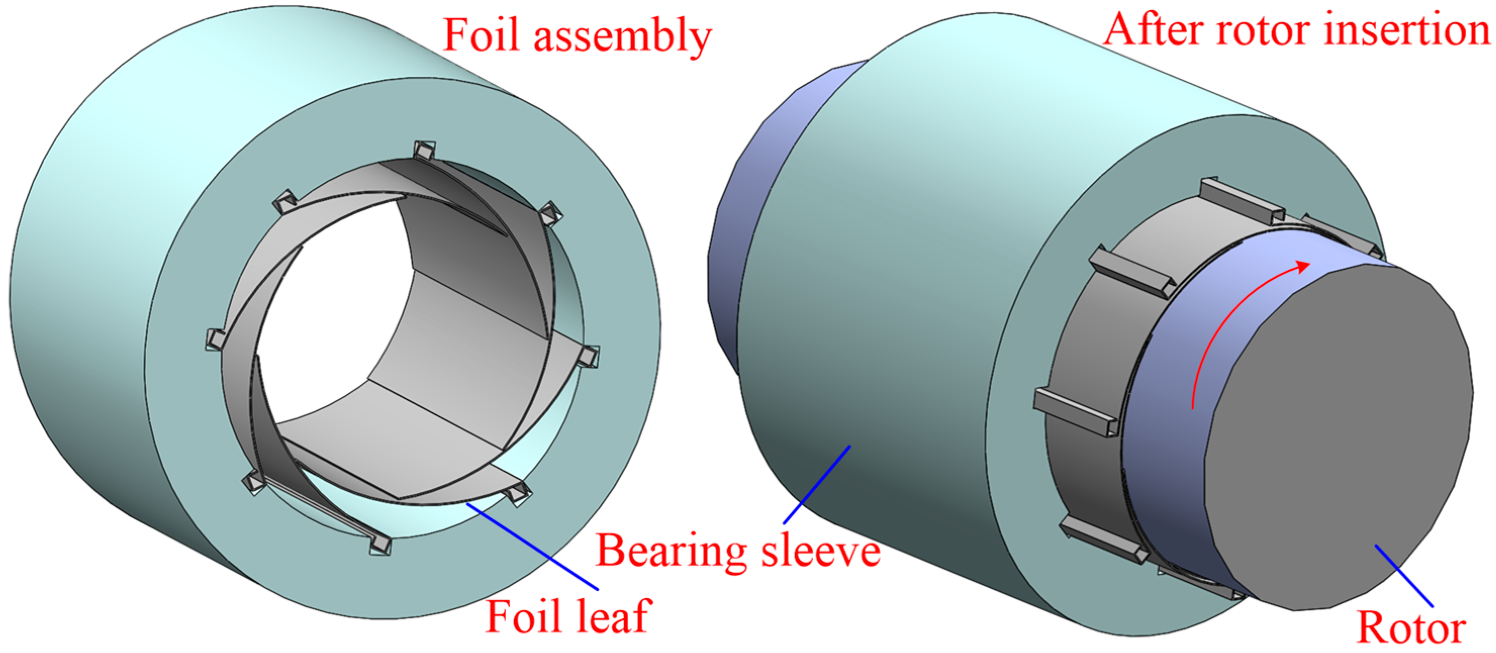
Figure 2.
Mesh generation of MLJFB with (a) different initial foil leaf positions and (b) a nonlinear curve beam element.
Figure 2.
Mesh generation of MLJFB with (a) different initial foil leaf positions and (b) a nonlinear curve beam element.
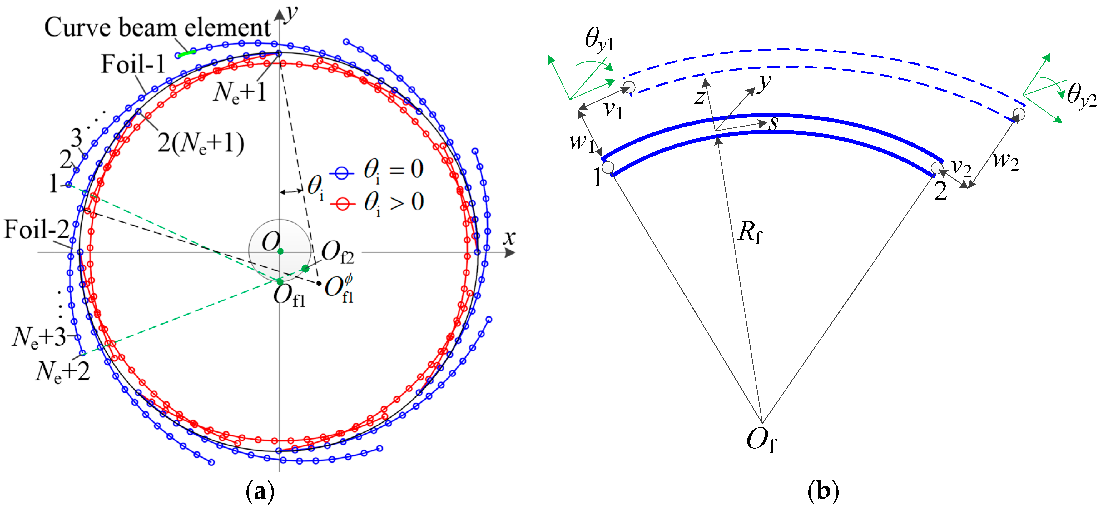
Figure 3.
Schematic of normal contact constraints in MLJFB.
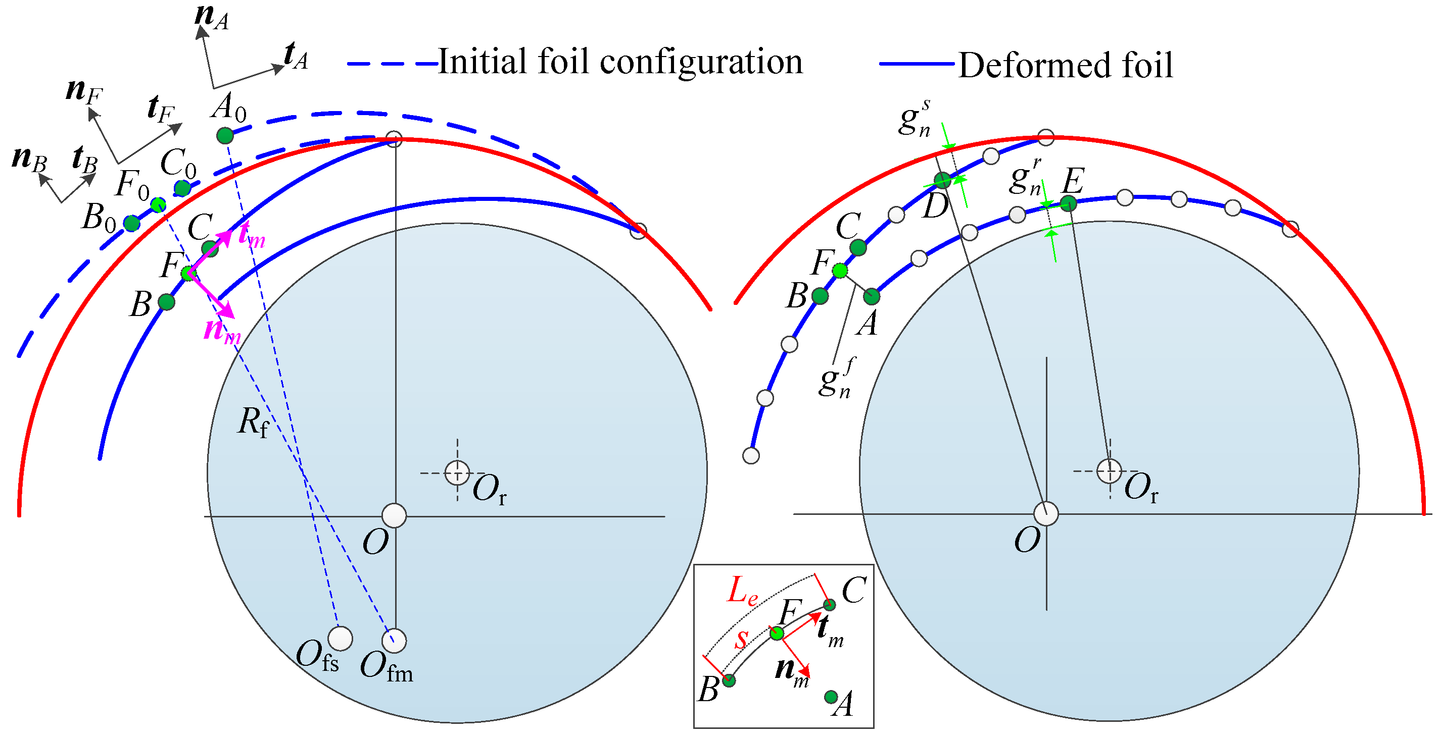
Figure 4.
Schematic of the tangent contact constraints in MLJFB with frictions.

Figure 5.
Schematic of the boundary conditions of the foil leaf.
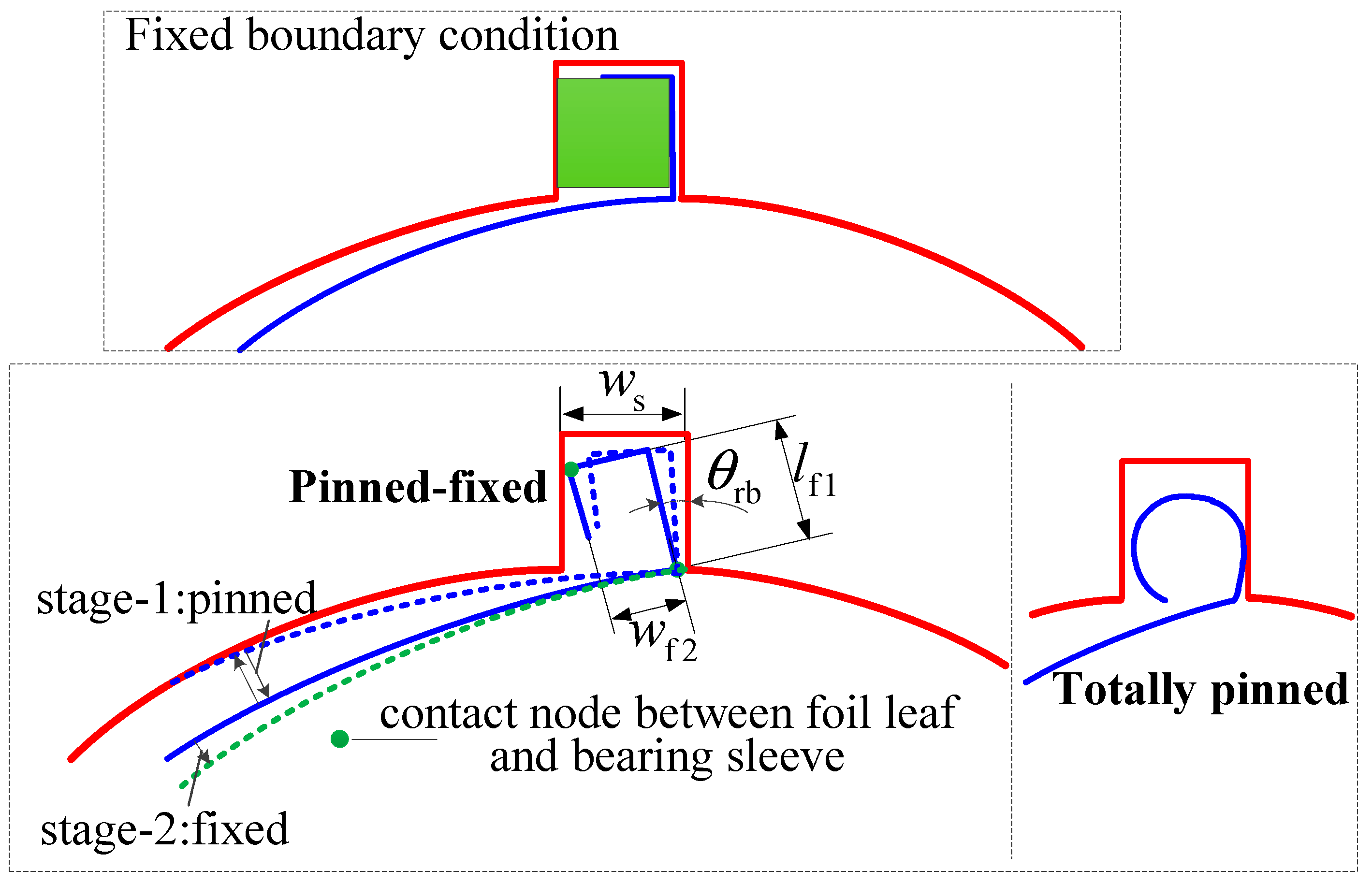
Figure 6.
Schematics of foil assembly, rotor insertion and static rotor loading processes of an eight-leaf MLJFB.
Figure 6.
Schematics of foil assembly, rotor insertion and static rotor loading processes of an eight-leaf MLJFB.
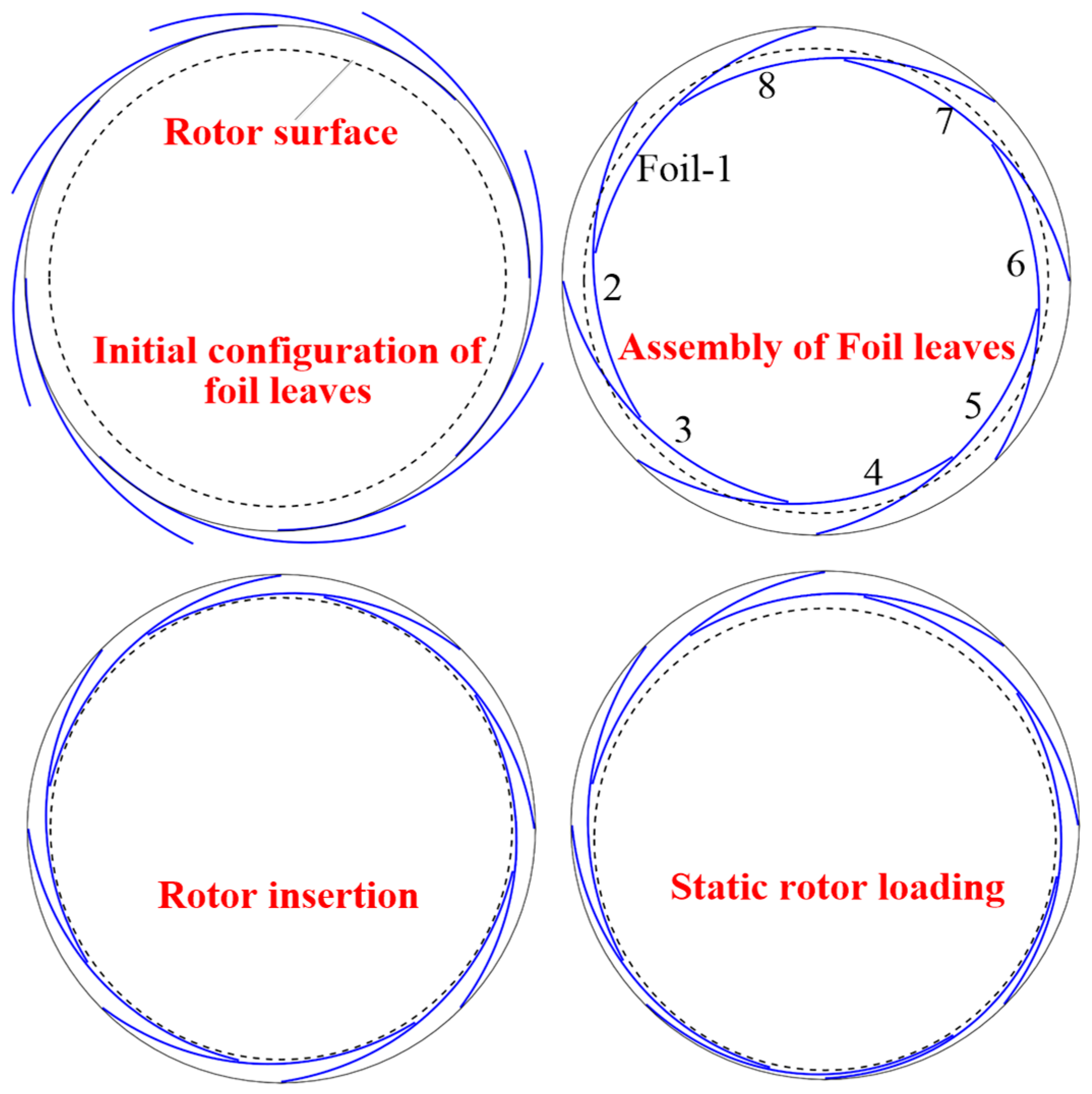
Figure 7.
Calculation algorithms of (a) foil assembly and (b) rotor insertion and static loading of MLJFB.
Figure 7.
Calculation algorithms of (a) foil assembly and (b) rotor insertion and static loading of MLJFB.

Figure 8.
Calculation results under linear and nonlinear curve beam elements: (a) foil assembly results under linear element, (b) foil assembly results under nonlinear element, (c) rotor insertion results and (d) static loading results.
Figure 8.
Calculation results under linear and nonlinear curve beam elements: (a) foil assembly results under linear element, (b) foil assembly results under nonlinear element, (c) rotor insertion results and (d) static loading results.

Figure 9.
(a) Nodes series of the foil leaf and (b) the schematic of the sliding direction between adjacent foil leaves.
Figure 9.
(a) Nodes series of the foil leaf and (b) the schematic of the sliding direction between adjacent foil leaves.
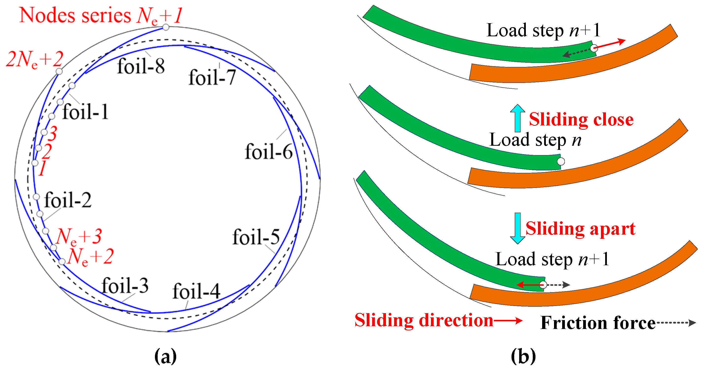
Figure 10.
Calculation results influenced by friction coefficient μ: (a) static loading–unloading results, (b) contact states under μ = 0.1, (c) contact states under μ = 0.2 and (d) contact states under μ = 0.3.
Figure 10.
Calculation results influenced by friction coefficient μ: (a) static loading–unloading results, (b) contact states under μ = 0.1, (c) contact states under μ = 0.2 and (d) contact states under μ = 0.3.
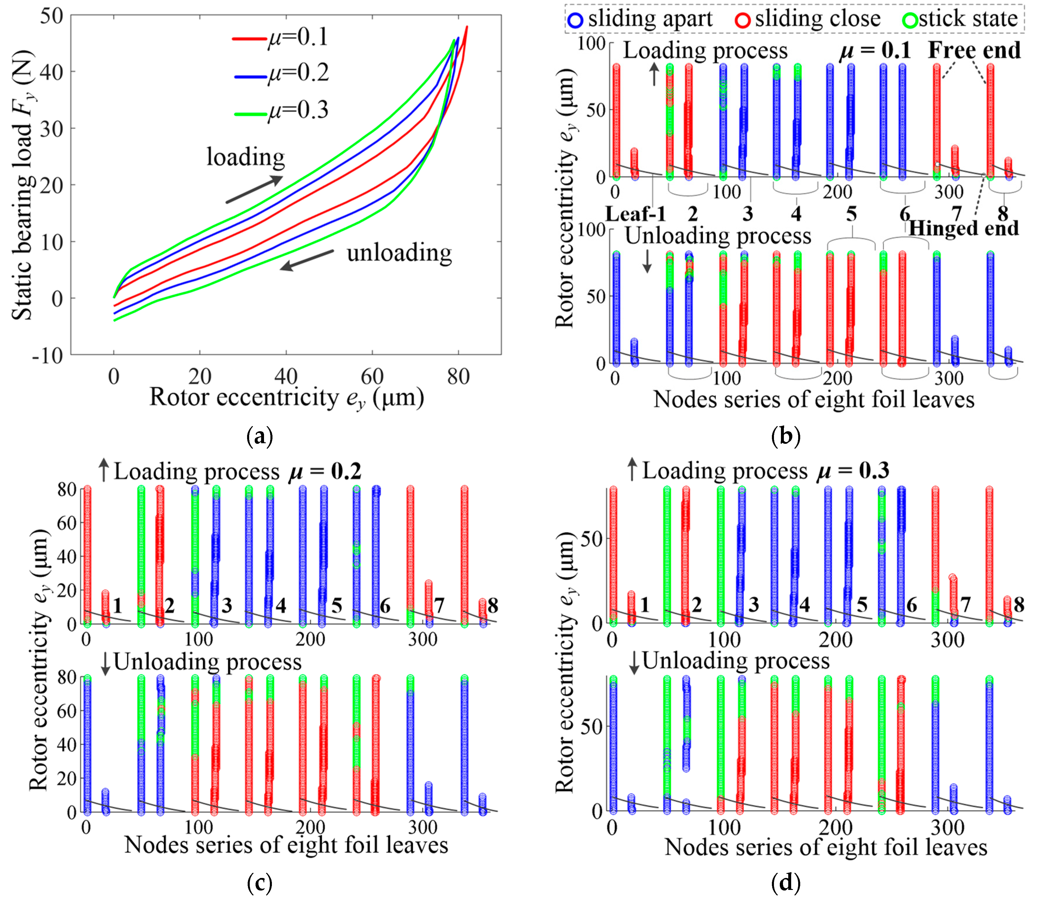
Figure 11.
Influence of the (a) foil leaf boundary condition on the (b) static loading–unloading results.
Figure 11.
Influence of the (a) foil leaf boundary condition on the (b) static loading–unloading results.
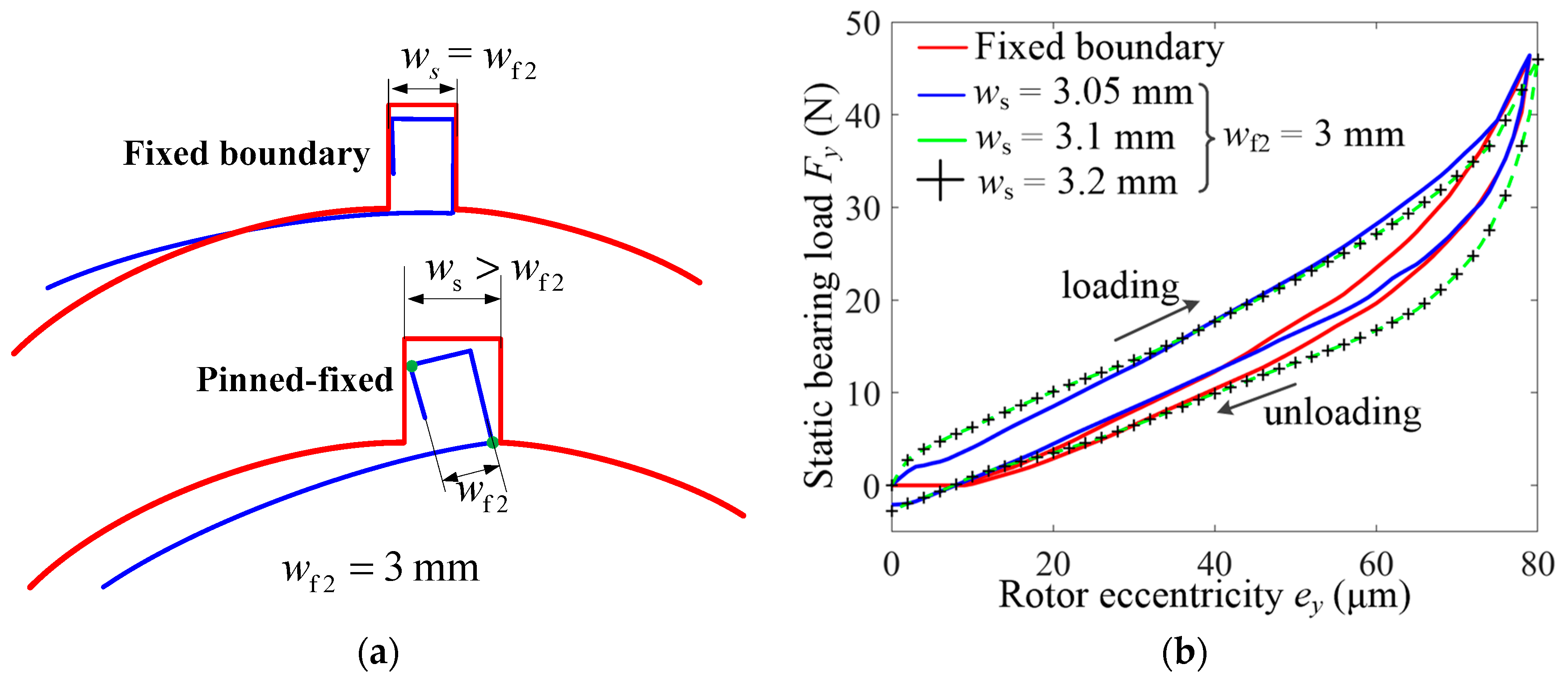
Figure 12.
Calculation results influenced by the foil leaf boundary condition: (a) contact forces under ws = 3 mm, (b) contact forces under ws = 3.05 mm, (c) contact states under ws = 3 mm and (d) contact states under ws= 3.05 mm.
Figure 12.
Calculation results influenced by the foil leaf boundary condition: (a) contact forces under ws = 3 mm, (b) contact forces under ws = 3.05 mm, (c) contact states under ws = 3 mm and (d) contact states under ws= 3.05 mm.
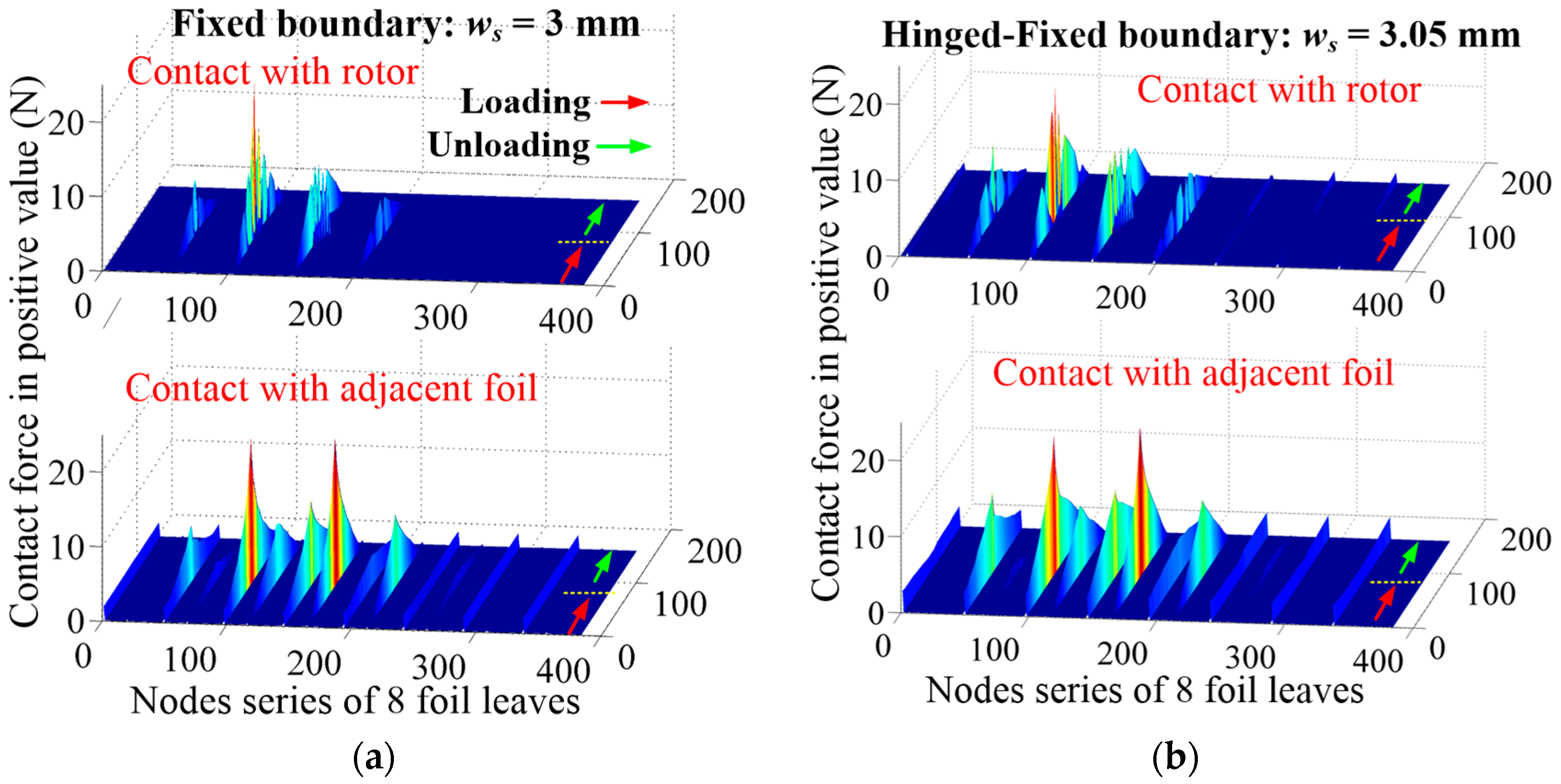

Figure 13.
Influence of the (a) foil leaf number on the (b) static loading–unloading results.
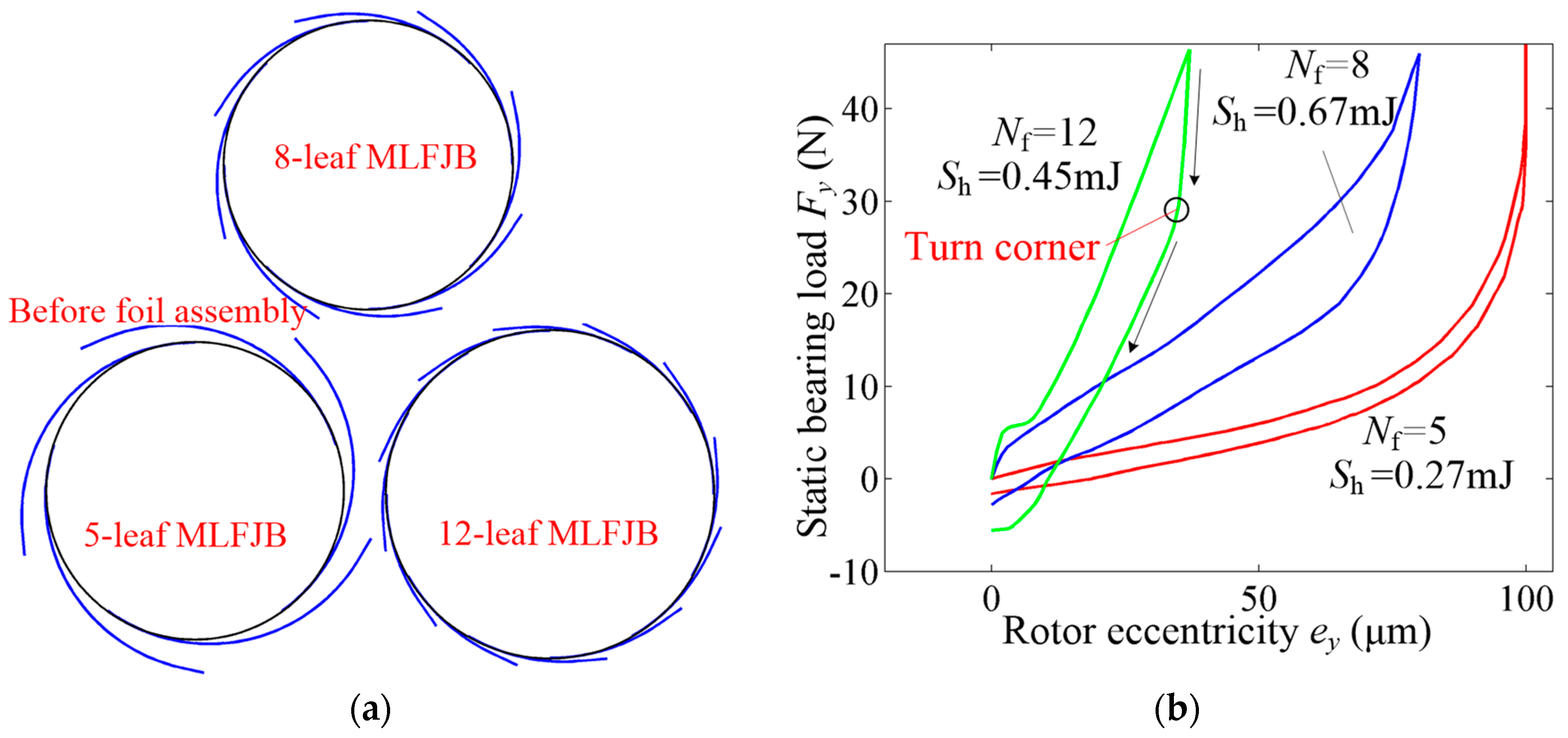
Figure 14.
Calculation results influenced by the foil leaf number: (a) contact forces under Nf = 5, (b) contact forces under Nf = 12, (c) contact states under Nf = 5 and (d) contact states under Nf = 12.
Figure 14.
Calculation results influenced by the foil leaf number: (a) contact forces under Nf = 5, (b) contact forces under Nf = 12, (c) contact states under Nf = 5 and (d) contact states under Nf = 12.

Figure 15.
Influence of the (a) radial clearance on the (b) static loading–unloading results.
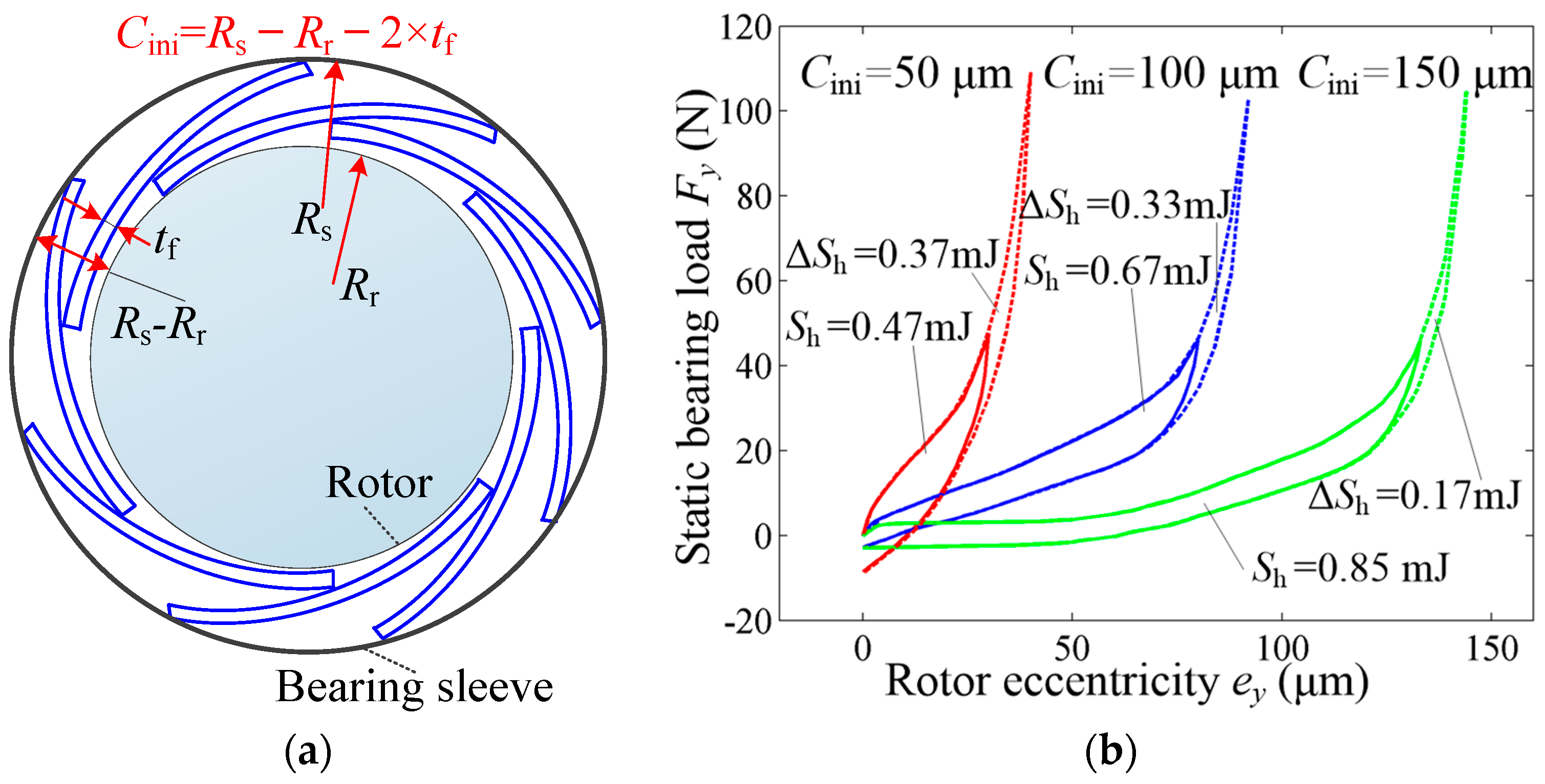
Figure 16.
Calculation results influenced by radial clearance: (a) contact forces under Cini = 50 μm, (b) contact forces under Cini = 150 μm, (c) contact states under Cini = 50 μm and (d) contact states under Cini = 150 μm.
Figure 16.
Calculation results influenced by radial clearance: (a) contact forces under Cini = 50 μm, (b) contact forces under Cini = 150 μm, (c) contact states under Cini = 50 μm and (d) contact states under Cini = 150 μm.
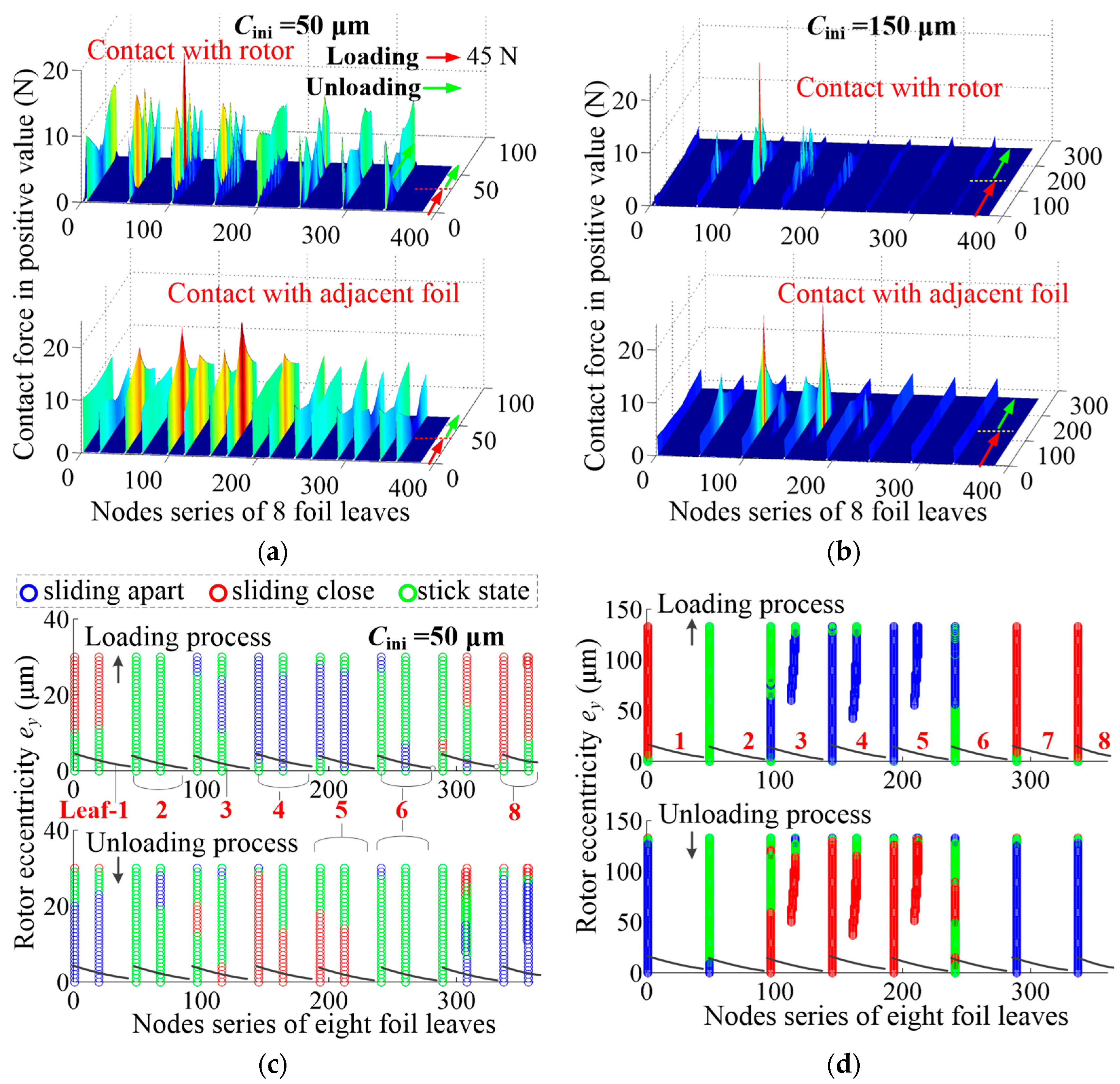
Figure 17.
Influence of the (a) initial foil leaf radius on the (b) static loading–unloading results.
Figure 17.
Influence of the (a) initial foil leaf radius on the (b) static loading–unloading results.
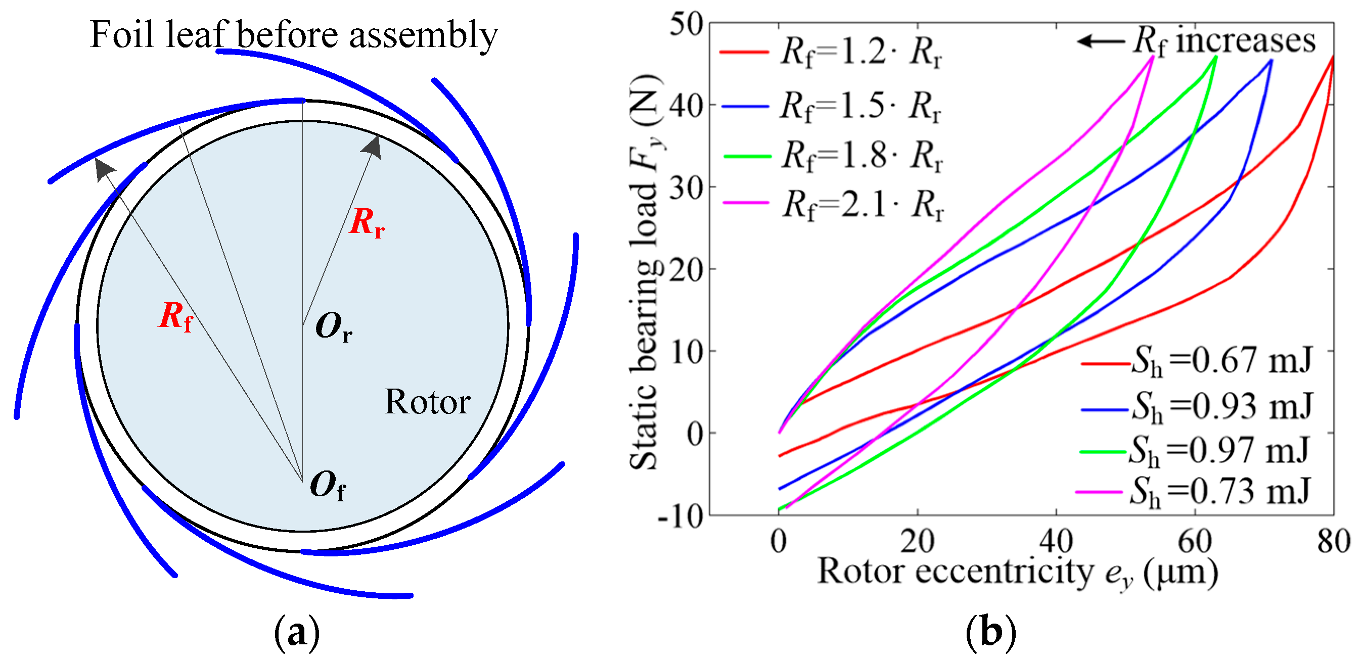
Figure 18.
Calculation results influenced by the initial foil leaf radius: (a) contact forces under Rf = 1.2 × Rr, (b) contact forces under Rf = 2.1 × Rr, (c) contact states under Rf = 1.8 × Rr and (d) contact states under Rf = 2.1 × Rr.
Figure 18.
Calculation results influenced by the initial foil leaf radius: (a) contact forces under Rf = 1.2 × Rr, (b) contact forces under Rf = 2.1 × Rr, (c) contact states under Rf = 1.8 × Rr and (d) contact states under Rf = 2.1 × Rr.

Figure 19.
Influence of (a) foil leaf thickness on the (b) static loading–unloading results.
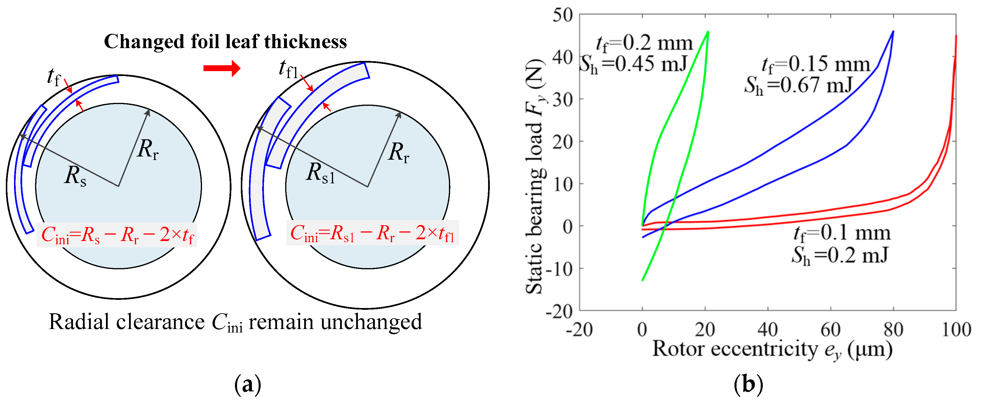
Figure 20.
Calculation results influenced by foil leaf thickness: (a) contact forces under tf = 0.1 mm, (b) contact forces under tf = 0.2 mm, (c) contact states under tf = 0.1 mm and (d) contact states under tf = 0.2 mm.
Figure 20.
Calculation results influenced by foil leaf thickness: (a) contact forces under tf = 0.1 mm, (b) contact forces under tf = 0.2 mm, (c) contact states under tf = 0.1 mm and (d) contact states under tf = 0.2 mm.
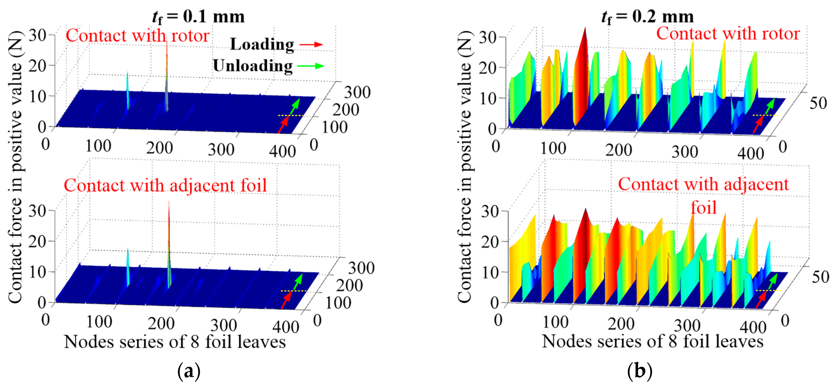

Figure 21.
Influence of the (a) foil leaf overlapping ratio on the (b) static loading–unloading results.
Figure 21.
Influence of the (a) foil leaf overlapping ratio on the (b) static loading–unloading results.
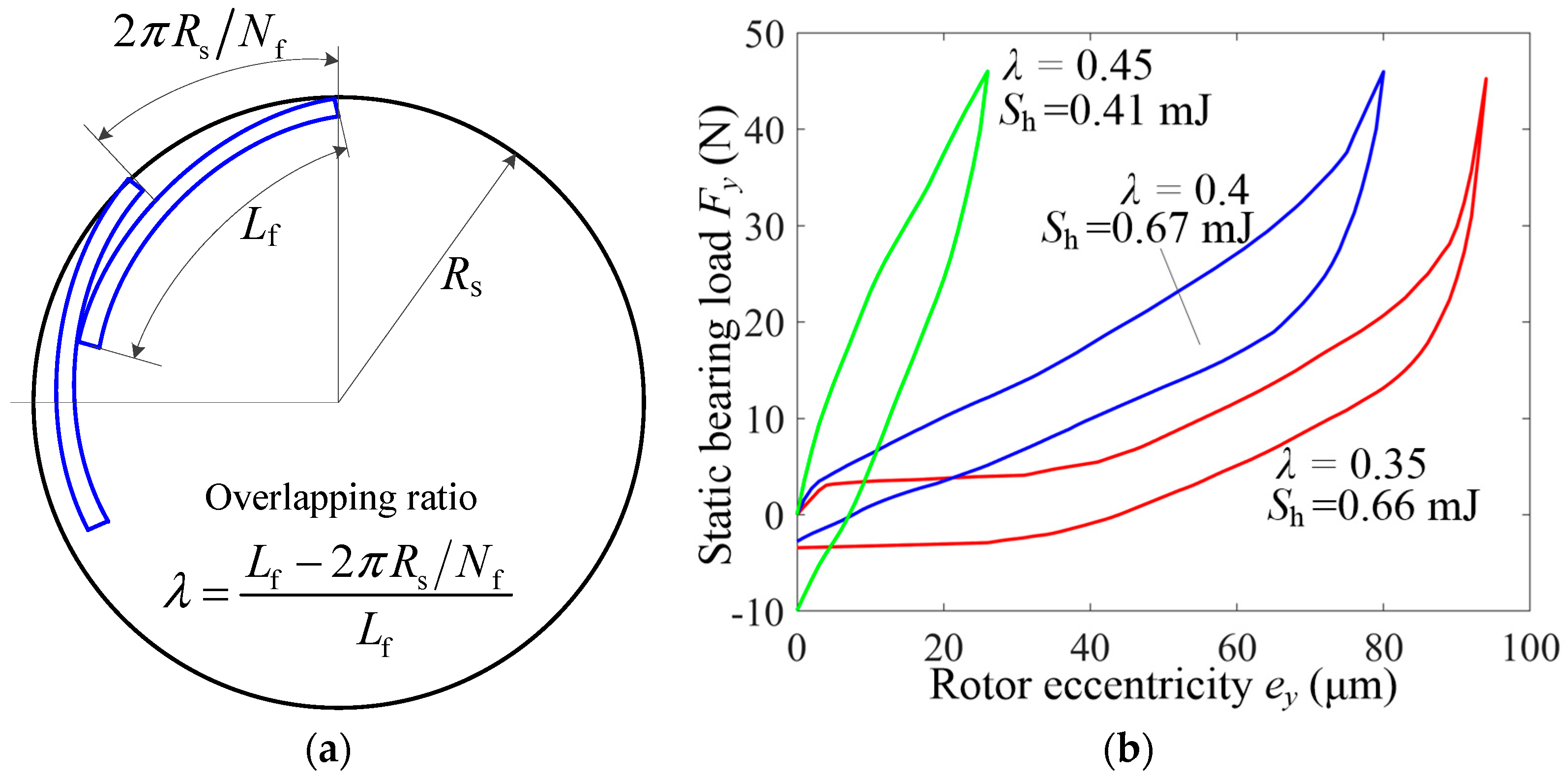
Figure 22.
Calculation results influenced by the foil leaf overlapping ratio: (a) contact forces under λ = 0.35, (b) contact forces under λ = 0.45, (c) contact states under λ = 0.35 and (d) contact states under λ = 0.45.
Figure 22.
Calculation results influenced by the foil leaf overlapping ratio: (a) contact forces under λ = 0.35, (b) contact forces under λ = 0.45, (c) contact states under λ = 0.35 and (d) contact states under λ = 0.45.
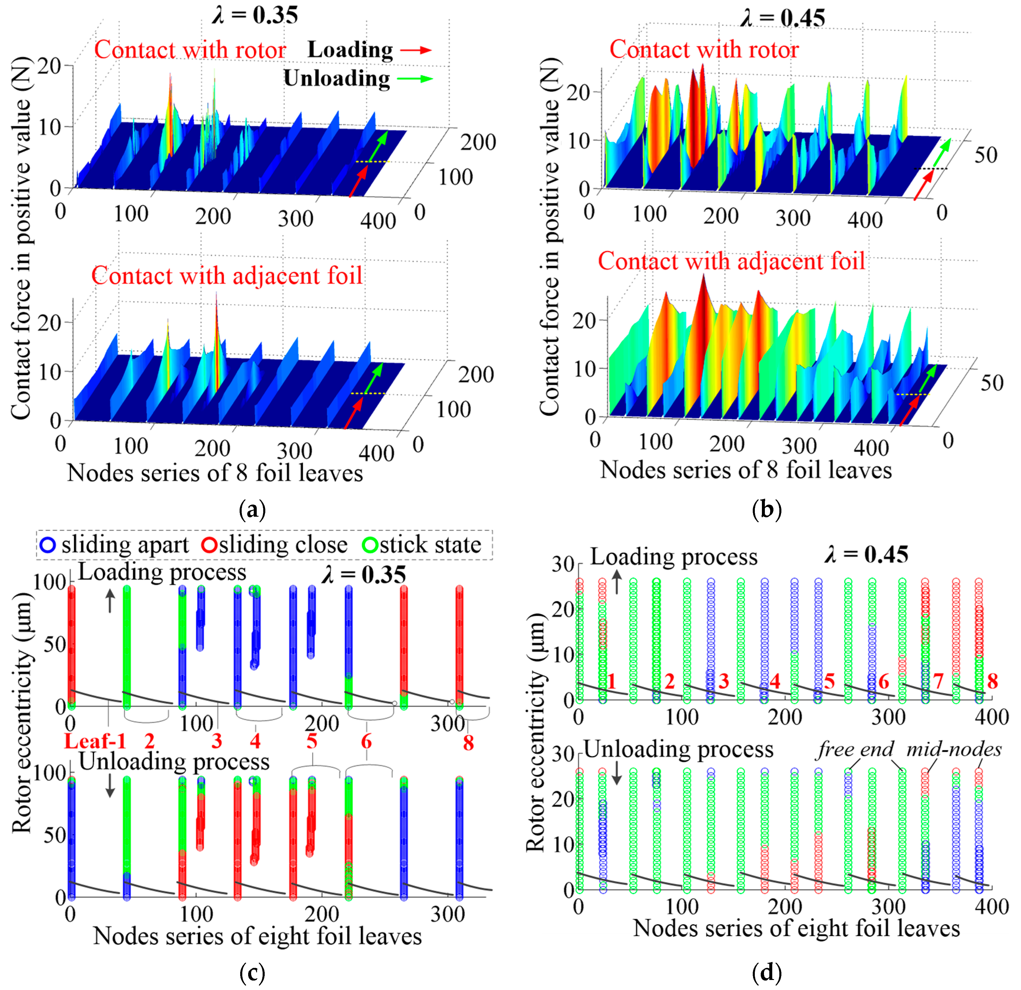
Figure 23.
Comparison of foil assembly results between simulations and test pieces.

Figure 24.
Test rig and schematic of the static loading–unloading measurements.

Figure 25.
Comparisons of static loading–unloading curves between simulations and test results under different: (a) foil leaf numbers, (b) initial foil leaf radii, (c) foil overlapping ratios and (d) foil leaf thicknesses.
Figure 25.
Comparisons of static loading–unloading curves between simulations and test results under different: (a) foil leaf numbers, (b) initial foil leaf radii, (c) foil overlapping ratios and (d) foil leaf thicknesses.


Table 1.
Calculation parameters.
| Parameters | Values |
|---|---|
| Rotor diameter Dr/mm | 35 |
| Rotor radius Rr/mm | 17.5 |
| Bearing width L/mm | 35 |
| Foil leaf number | 5, 8, 12 |
| Foil leaf radius Rb/mm | 1.2 × Rr, 1.5 × Rr, 1.8 × Rr, 2.1 × Rr |
| Foil leaf thickness tf/mm | 0.1, 0.15, 0.2 |
| Overlapping ratio λ | 0.35, 0.4, 0.45 |
| Initial radial clearance Cini/μm | 50, 100, 150, 200 |
| Friction coefficient between foil leaves μ | 0, 0.1, 0.2, 0.3 |
Publisher’s Note: MDPI stays neutral with regard to jurisdictional claims in published maps and institutional affiliations. |
© 2022 by the authors. Licensee MDPI, Basel, Switzerland. This article is an open access article distributed under the terms and conditions of the Creative Commons Attribution (CC BY) license (https://creativecommons.org/licenses/by/4.0/).
Share and Cite
MDPI and ACS Style
Li, C.; Du, J.; Li, J.; Xu, Z. Investigations on the Frictional Hysteresis Effect of Multi-Leaf Journal Foil Bearing: Modeling, Predictions and Validations. Lubricants 2022, 10, 261. https://doi.org/10.3390/lubricants10100261
AMA Style
Li C, Du J, Li J, Xu Z. Investigations on the Frictional Hysteresis Effect of Multi-Leaf Journal Foil Bearing: Modeling, Predictions and Validations. Lubricants. 2022; 10(10):261. https://doi.org/10.3390/lubricants10100261
Chicago/Turabian StyleLi, Changlin, Jianjun Du, Jie Li, and Zhenni Xu. 2022. "Investigations on the Frictional Hysteresis Effect of Multi-Leaf Journal Foil Bearing: Modeling, Predictions and Validations" Lubricants 10, no. 10: 261. https://doi.org/10.3390/lubricants10100261
Note that from the first issue of 2016, this journal uses article numbers instead of page numbers. See further details here.