Nonlinear Dynamic Analysis of a Spur Gear Pair System with Wear Considering the Meshing Position


1
Yangtze Delta Region Institute, University of Electronic Science and Technology of China, Huzhou 313000, China
2
School of Aeronautics and Astronautics, University of Electronic Science and Technology of China, Chengdu 611731, China
3
College of Mechanical and Vehicle Engineering, Chongqing University, Chongqing 400044, China
4
School of Mechanical Engineering, Bejing Institute of Technology, Beijing 100081, China
*
Authors to whom correspondence should be addressed.
Lubricants 2024, 12(1), 25; https://doi.org/10.3390/lubricants12010025
Submission received: 5 November 2023
/
Revised: 29 December 2023
/
Accepted: 3 January 2024
/
Published: 16 January 2024
(This article belongs to the Special Issue Friction–Vibration Interactions)
Abstract
:In this paper, a nonlinear dynamic model of a parallel shaft gear system consisting of two involute spur gears is developed to investigate the coupling effect between the gradual surface wear of gear teeth over time and nonlinear dynamic characteristics. A uniform wear model that accounts for how the volumetric wear of the gear teeth affect their meshing position, backlash, and stiffness is proposed. Additionally, a nonlinear dynamic model with six degrees of freedom is described that considers friction, time-varying gear backlash, and time-varying meshing stiffness. The proposed model significantly changes the mesh stiffness, not only in terms of value but also in terms of contact ratio. Furthermore, the nonlinear dynamic characteristics of the gear system vary significantly. It is found that the gradual wear of gear teeth affects the meshing position and further has a significant impact on the nonlinear dynamic characteristics of the spur gear system. This paper provides a basis for studying the nonlinear dynamic characteristics of the spur gear system as it experiences the gradual wear of teeth over time.
1. Introduction
Gear systems are important components of mechanical transmission systems and are widely used in various industrial applications for their numerous benefits. However, gear failures can result in downtime and increased maintenance costs, significantly impacting industrial productivity. Among the various types of gear faults, wear is the most common, and directly affects the dynamic characteristics of gear systems. Tooth surface wear gradually worsens over time, leading to gear system failures and repercussions. Therefore, it is essential to study the coupling of gear dynamic sand wear to better comprehend how wear affects gear system performance and to develop more durable and efficient gear systems.
Previous research has extensively investigated nonlinear dynamic behaviors of transmission systems [1,2,3], with a variety of focus areas. For example, a model of planetary gear was established that introduced nonlinearity by bearing clearance [4]. Farshidianfar and Saghafi [5] employed the Melnikov analytical method to establish a model of a gear transmission system and analyze its bifurcation, considering parameters such as backlash, external excitation, and other system characteristics. Additional research proposed methods to examine different types of bifurcation curves generated by the intersection of bifurcation diagrams [6], and presented bifurcation diagrams of gear transmission systems using various parameter settings [7,8,9]. These studies have contributed valuable insights into the nonlinear dynamic behavior of spur gear systems.
However, it is worth noting that these studies generally do not consider the effects of wear, pitting, scoring, and cracking, which are some of the most common types of gear failure. In reality, these failures occur gradually during operation over time under severe conditions [10,11,12]. It is well known that the lubrication condition [13,14] and interfacial profile, such as the gear wear profile [15] and bearing profile [16], are crucial factors affecting the dynamic response of transmission system. Therefore, it is important to expand upon these previous studies by examining the effects of gear failures, on nonlinear dynamic behavior. Meng et al. [17] proposed a new modeling method for tooth pitting, based on a matrix equation that evaluated meshing stiffness. However, these studies have not generally considered the effects of gear failures, such as wear, pitting, scoring, and cracking.
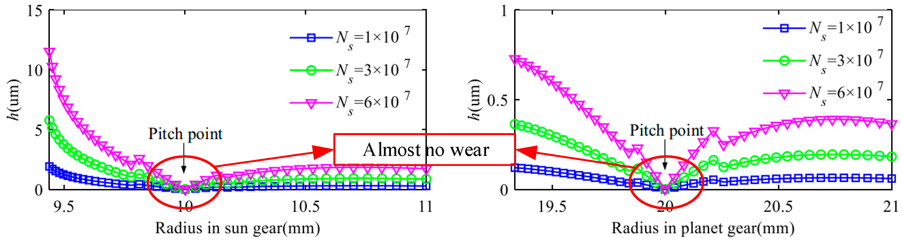
Wear is one of the most common failures when one surface moves onto another surface under rolling or sliding conditions [18,19]. Meanwhile, wear also has a significant impact on fatigue [20]. In recent years, researchers have increasingly focused on the relationship between gear dynamics and wear, exploring the coupling between these two phenomena. For instance, Yuksel [21] conducted dynamic response analysis by considering surface wear, while Archard theory [22] was employed to calculate wear depth distribution. Li et al. [15] developed a dynamic model of a gear-bearing system based on fractal theory, incorporating wear depth into the calculation of backlash and stiffness to investigate the interaction between wear and dynamic characteristics. Shen et al. [23] developed a wear model of planetary gears and calculated the wear depth of the tooth surfaces in different meshing cycles (as exhibited in Figure 1). Meanwhile, Zhan et al. [24] conducted experiments on tooth surface wear (as demonstrated in Figure 2) and further investigated how worn gears affect transmission errors. Zhang et al. [25] proposed a wear dynamic model that considers the interaction between wear and dynamic response and takes contact temperature into account. However, there is still much to learn about how wear influences the dynamic characteristics of gear systems, and research on the topic is ongoing. Much research has focused on tooth wear, and some studies have noted that tooth wear does not consider the change in meshing position after wear.
Although gear wear is generally non-uniform, some researchers have studied the impact of uniform wear on gear systems for theoretical discussion. For example, Koffi et al. [26] analyzed the vibration displacement of plastic gears exhibiting uniform wear and found that it could lead to significant changes in gear system performance. Feng et al. [27] assumed uniform tooth wear and developed a model to determine the meshing stiffness of a gear pair with wear, incorporating factors such as tooth geometry and material properties. Zhou et al. [28] combined the generalized sliding distance model and enhanced coordinate transformation to propose a prediction model for the adhesive wear of double helical gears. Their results suggest that uniform wear can actually improve gear wear resistance. Geng [29] established a nonlinear dynamic model that considers uniform wear to analyze the bifurcation diagrams, phase diagrams, Poincaré maps, time series, and FFT spectra of a rigid–flexible gear pair. Sheng [30] proposed a dynamic model to investigate the effects of uniform wear on gear tooth failures, providing a comprehensive analysis of bifurcation characteristics in gear systems.
Several studies have analyzed the dynamic characteristics of gear systems with wear, which may cause changes to the tooth profile, leading to changes in the meshing point, gear backlash, contact ratio, meshing stiffness, and transmission error. However, in previous studies, the meshing position remained unchanged after wear. The innovation of this paper lies in considering the change in the meshing position caused by uniform wear. In this paper, we consider the effects of uniform wear on the meshing position, contact ratio, gear backlash, and meshing stiffness on dynamic responses. Further, we analyze the nonlinear dynamic characteristics of the gear pair. This paper improves our understanding of the impact of uniform wear on the nonlinear dynamic behavior of gear transmission systems and may provide valuable insights for designing and maintaining gear systems.
2. Nonlinear Dynamic Model of the Gear System
2.1. The Gear Backlash Function
The model of the gear pair is presented in Figure 3. The length of the meshing line can be calculated as follows:
where subscripts 1 and 2 represent the driving gear and driven gear, respectively; lm represents the length of the meshing line; ra and rb represent the radius of the addendum and root radius, respectively; α0 represents the pressure angle; a represents the center distance of the gear pair.
According to the property of the involute, the length of the meshing line is equal to the tooth profile. Based on the Archard theory [22],
where V represents the wear volume; W represents the meshing force; s represents the relatively sliding displacement; k represents the wear coefficient; H represents the hardness.
The relatively sliding displacement in a meshing period is as follows:
where tT is the operating time; u is the sliding speed on the meshing point; ɛ is the contact ratio; n and z are, respectively, the rotational speed and tooth number [26].
The relatively sliding displacement can be derived as x = sn1t/60. The wear depth can be expressed as follows:
where dW is the wear depth; BW is the tooth width. Based on [31], the gear backlash function can be obtained as follows:
where bm is half of the total gear backlash and Y is the dynamic transmission error.
2.2. The Contact Ratio of the Gear Pair
The diagram of the gear with wear is presented in Figure 4. The coordinates of points A, A1, B, B1, C, C1, O, O1, and E are (x1, y1), (x2, y2), (x3, y3), (x4, y4), (x5, y5), (x6, y6), (x7, y7), (x8, y8), and (x9, y9), respectively. The coordinates of (x7, y7) are (0, 0).
where, r1 is the basic circle of the driving gear, ha is the addendum coefficient, mn is the modulus. The coordinate of point A can be obtained as follows:
where α0 is the standard pressure angle.
Therefore, the coordinate of point A1 can be written as (x1-hp, y1), where hp is the wear depth.
Due to the coordinate of point C1 being (−0.5hp, y1), the equation of A1B1 can be written as follows:
The equation of the circle can be expressed as follows:
Substituting Equation (10) into Equation (11) yields the following:
The coordinate of point B1 can be obtained via Equation (13). The length of A1B1 can be calculated via the following:
The equation of B1O1 can be obtained as follows:
The value of P can be solved by substituting the coordinates of point B1. The abscissa of point O1 is −0.5hp, and the ordinate can be solved using the equation. Therefore, the length of B1O1 can be derived as following:
The length of A1O1 can be obtained via the Pythagorean theorem. Based on the sine theorem,
According to the similar triangle theorem, the meshing angle under wear can be obtained as follows:
Therefore, the contact ratio of the gear pair after wear can be calculated via the following:
where z1 and z2 are, respectively, the tooth number of the driving gear and driven gear; α′ is the meshing angle with wear; α′a1 and α′a2 are, respectively, the pressure angle of addendum of the driving gear and driven gear with wear.
2.3. The Meshing Stiffness of the Gear Pair with Wear
The uniform cantilever beam model of the spur gear tooth with uniform wear is shown in Figure 5. According to Figure 5, the arc angle of the gear α′2 can be derived using O1E. The coordinate of the point O1 is calculated in the previous section, and the abscissa and ordinate of the point E can be obtained as follows:
where α is the standard pressure angle, α2 is the arc angle of the gear without wear, and z1 is the tooth number of the driving gear.
The method to derive the meshing stiffness is in accordance with [32], and the axial compressive stiffness, bending stiffness and shear stiffness can be expressed, respectively, as follows:
where Ix, E, G, and Ax are, respectively, the area moment of inertia, Young’s modulus, shear modulus, and area of the section; x is the distance between the contact point of the meshing force and section in Figure 2. α′1 is marked in Figure 2. They can be calculated via the following:
The parameters in the above equations can be derived via the following:
Therefore, the bending stiffness, shear stiffness, and axial compressive stiffness can be calculated based on the above equations.
The stiffness with a consideration of the gear fillet foundation deflection, kfi (i = 1, 2), and the Hertzian contact stiffness, kh, can be obtained based on [30], and these have no relationship with wear.
The Hertzian contact stiffness (kh) and the stiffness of the gear fillet foundation deflection were calculated in accordance with the method proposed by Chen and Shao [33]. kh and kf can be expressed as follows:
The expressions of these parameters were derived by Xie et al. [34].
Consequently, time-varying meshing stiffness can be calculated based on the above equations.
where α0 is the standard pressure angle, α1 is the pressure angle at any point, α2 is the corresponding arc angle of half tooth, and α is the integral variable.
2.4. Friction Force and Friction Moment
The relative sliding of the gear teeth during the meshing process results in friction forces. The directions of friction forces varies with the meshing position. Coulomb’s law is applied to calculate the friction forces
where μi is the friction coefficient; λi is the directional coefficient, which can be derived from [31].
μi can be described as follows:
where Vi is the relative sliding between the ith pair of teeth, which can be obtained as follows:
where w1 and w2 are the angular velocities of the driving gear and driven gear, respectively; L1i and L2i are the friction arms between the ith pair of teeth. The friction arms of the gear pair can be expressed as follows:
where t1, t2 are, respectively, the meshing time in a period of the 1st and 2nd tooth pair.
2.5. Nonlinear Dynamic Model of the Gear Pair
The nonlinear dynamic model of the gear pair was established as follows:
where subscripts 1 and 2 are, respectively, the driving gear and driven gear. m is the mass. x, y and θ are the vibration displacement in the x direction, the vibration displacement in the y direction and the angular displacement, respectively. crx and krx represent the bearing support damping and the bearing support stiffness in the x direction, respectively. cry and kry represent the bearing support damping and the bearing support stiffness of the driving gear in the y direction, respectively. T1 and T2 are the input and output torques, respectively.
The non-dimensional time, τ, can be described as τ = wnt. wn is the natural frequency, wn = (kn/meq)1/2, where meq is the equivalent mass of the gear pair; kn is the average value of the meshing stiffness. bc is introduced in this process, and is the nominal displacement scale. The non-dimensional parameters can be calculated as follows:
ξr1x = cr1x/m1wn, ξr1y = cr1y/m1wn, ξm1 = ξm2 = cm/m1wn, ξm3 = ξm4 = cmrb1/I1wn, ηr1x = kr1x/m1wn2, ηr1y = kr1y/m1wn2, ηm1 = km1/m1wn2, ηm2 = km2/m1wn2, ηm3 = km1rb1/I1wn2, ηm4 = km2rb1/I1wn2, ηm5 = km1/m2wn2, ηm6 = km2/m2wn2, ξm5 = ξm6= cm/m2wn, ηm7 = km1rb2/I2wn2, ηm8 = km2rb2/I2wn2, ξm7 = ξm8 = cmrb2/I2wn, ξr2x = cr2x/m2wn, ξr2y = cr2y/m2wn, ηr2x = kr2x/m2wn2, ηr2y = kr2y/m2wn2, f1 = T1/I1bcwn2, f2 = T2/I2bcwn2, Ω = w1/wn, Ω = w2/wn, E1 = ρ1/bc, E2 = ρ2/bc.
Therefore, Equation (16) can be expressed as
where, q1, q2, q3, q4, q5 and q6 correspond to the non-dimensional parameters x1, y1, θ1, x2, y2 and θ2. The gear backlash function in Equation (5) can be represented as follows:
The nonlinear parameters give rise to strong nonlinear characteristics, particularly when subjected to parametric excitation. Therefore, to investigate the system’s behavior, Equation (45) was solved numerically using a suitable numerical method. Table 1 summarizes the various parameters that characterize the gear system under consideration.
3. Numerical Results and Discussion
In this section, the effects of wear on the dynamic responses of the gear system are proposed. Equation (28) presents a non-dimensional model of the system with varying parameters, such as meshing stiffness and gear backlash. We analyze the dynamic characteristics of the gear system with wear by conducting numerical calculations based on these parameters. Specifically, the impact of wear on the system’s performance is evaluated by comparing the dynamic responses of the worn gear system with those of the unworn gear system. The numerical calculations use solving methods. To understand the methodology easily, a flowchart of the current investigation is represented in Figure 6, which outlines the steps taken to analyze the effects of wear on the dynamic responses of the proposed gear system.
Figure 7 shows the meshing stiffness of the gear pair based on the proposed model and a previous model for comparison. In this comparison, a previous model is examined to assess the impact of the proposed model on gear performance. When the meshing point is taken into consideration, the contact ratio and meshing stiffness of the gear pair show variation. In Figure 7a, it is shown that there were changes in the contact ratio when the gear pair was subject to wear, which in turn led to changes in the meshing time within the single- and double-tooth meshing areas. As shown in Figure 7b, the proposed model generates changes not only in the meshing stiffness, but also in the meshing periods of single- and double-tooth regions when compared to the traditional model. These results suggest that the proposed model better captures the effects of wear on gear performance and can more accurately predict the dynamic responses of the gear system when subjected to wear.
3.1. Influence of the Excitation Frequency
The excitation frequency is a critical factor governing the dynamic behavior of a gear transmission system. To assess the impacts of the excitation frequency on the nonlinear dynamic characteristics of the studied gear system, an excitation frequency range of 0.05–3 was selected. This range of frequency values was selected because it is a common operating range for gear transmission systems, and can provide insights into how the system responds to different frequencies. The excitation frequency was plotted on the horizontal axis and the non-dimensional vibration displacement of the driving gear was plotted on the vertical axis. We set the initial conditions of the excitation frequency to 0. We present the results of this analysis in Figure 8, which shows the bifurcation diagram and the spectrum waterfall diagram at different excitation frequencies. The bifurcation diagram displays the relationship between the excitation frequency and the system response, while the spectrum waterfall diagram provides a more detailed analysis of the system’s frequency response over time. These visualizations provide valuable insights into the nonlinear dynamic behavior of the gear system and can help to guide the development of more accurate models for predicting gear system performance.
The behavior of the gear system is highly dependent on the excitation frequency. When the excitation frequency is less than 0.55, the gear system exhibits a periodic motion, which is desirable for gear system performance. However, at several excitation frequencies, we observe the appearance of “frequency jumps”, which indicate that the motion state of the gear system has become unstable. At an excitation frequency of 0.55, the system transitions to a quasi-periodic motion. As the excitation frequency increases, the differences in vibration displacement at different periods decrease gradually, and the gear system returns to a period 1 motion state around the excitation frequency of 0.75. When the excitation frequency is 0.6, as shown in Figure 9, the time series shows that the gear system has a normal meshing process and a regular motion pattern to a certain degree. Moreover, the points on the Poincaré map are clustered but not coincident, and the phase diagram corresponds to the Poincaré map in every period with different trajectories. The FFT spectrum also has some peaks. These results suggest that the gear system is in quasi-periodic motion, which provides valuable insights into the nonlinear dynamic behavior of the gear system and can guide the development of more accurate models for predicting gear system performance.
The gear system exhibits periodic motion between excitation frequencies of 0.75 and 0.88, which is ideal for its performance. In Figure 10, regular waves in the time series indicate normal meshing and consistent motion. The phase diagram has only one closed curve, suggesting the gear system returns to the same state after each period. The Poincaré map shows a single point, and the FFT spectrum has peaks at 1, 2, and 3, all pointing to periodic motion. However, a “frequency jump” occurs at an excitation frequency of 0.89, which signifies a transition from periodic motion to quasi-periodic motion.
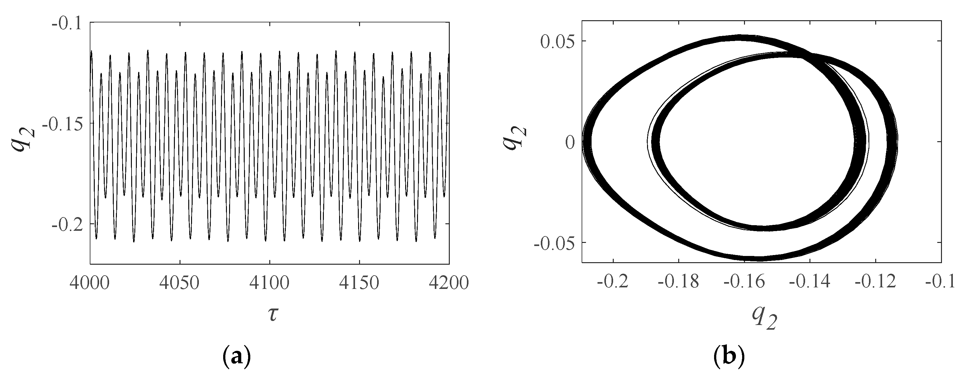
At an excitation frequency of 1.1, as shown in Figure 11, the waves in the time series are somewhat regular. The phase diagram displays similar shapes in each period but different trajectories. The Poincaré map has an unenclosed loop, and the FFT spectrum shows multiple peaks, which indicate the quasi-periodic motion of the system. This motion can yield insights into the nonlinear dynamics of the gear system and offer guidance for the development of accurate models that predict its performance. However, further analysis is necessary to identify any potential issues or concerns resulting from the quasi-periodic motion in the system at that excitation frequency.
With increasing excitation frequency, the gear system transitions from quasi-periodic to periodic motion. The system enters a periodic motion regime when the frequency exceeds 1.44, lasting until w = 2.52. As shown in Figure 12, at w = 2.7, the Poincaré map reveals two strange attractors, and the FFT spectrum has peaks at 0.5 and 1, indicating quasi-periodic-2 motion. The system transitions back to the periodic motion regime above 2.82 and remains in it. The Poincaré map shows the intersection of behavior with a specific hyperplane, providing insights into nonlinear dynamics. The FFT spectrum analyzes vibration frequencies for a detailed view of system behavior. Stranger attractors suggest nonlinear complexity and sensitivity to initial conditions. Further analysis is required to identify any potential concerns from the quasi-periodic-2 motion regime at w = 2.7.
3.2. Influence of the Gear Wear
The gear system experiences a gradual wear depth increase, resulting in changes to gear meshing stiffness and gear backlash that can alter the gear system’s bifurcation characteristics over time. Figure 13 presents bifurcation diagrams comparing the traditional and proposed models, revealing differences in the models’ ability to capture changes over time. Bifurcation diagrams provide insights into nonlinear systems and help identify different modes that influence gear performance. As wear depth increases, the traditional and proposed models differ significantly in several areas, highlighting the need for an accurate prediction of wear depth and gear meshing stiffness to capture gear system behavior. Improved models that account for these variables can more accurately predict gear system behavior, leading to better gear system design and maintenance strategies.
Medium wear can impact the dynamic behavior of the gear system, affecting its phase diagram, Poincaré map, and FFT spectrum. In Figure 14, we present dynamic responses for the traditional and proposed models of the gear system with medium wear, excited at a 0.96 frequency. The traditional model’s phase diagram shows a closed curve with no intersection points while its Poincaré map has a single point, and the FFT spectrum has two peaks indicating periodic motion. By contrast, the proposed model’s Poincaré map displays an unenclosed loop, with the phase diagram matching the Poincaré map’s different trajectories every period. Its FFT spectrum has multiple peaks, demonstrating quasi-periodic motion. These results suggest that the proposed model may better capture the gear system’s behavior. Specific FFT spectrum peaks offer vibration behavior insights under medium wear. The proposed model’s quasi-periodic motion insights can guide the development of more accurate models for predicting gear system behavior under varying wear conditions.
The differences between the motion states of the traditional and proposed models in the region of 2.41–2.77 can have significant implications for gear performance. The unstable area of the proposed model is larger than that of the traditional model, indicating potentially higher levels of nonlinear behavior or sensitivity to initial conditions. At an excitation frequency of 2.55, we observe differences in the phase diagrams and Poincaré maps of the traditional and proposed models, shown in Figure 15. Both Figure 15a,b indicate that the gear system is in a quasi-periodic-2 motion regime. However, the trajectories in the phase diagram of the traditional model and proposed model differ. The Poincaré map in Figure 15a has two strange attractors, while the Poincaré map in Figure 15b has two Hopf rings, suggesting that the bifurcation types of the two models differ. These diagrams provide valuable insights into the behavior of the gear system under different excitation frequencies and models, and help identify key differences that can have significant impacts on gear performance. Further analysis is needed to determine any specific concerns or recommendations arising from these differences in behavior, and to develop more accurate models that can more effectively predict gear system behavior under a range of conditions.
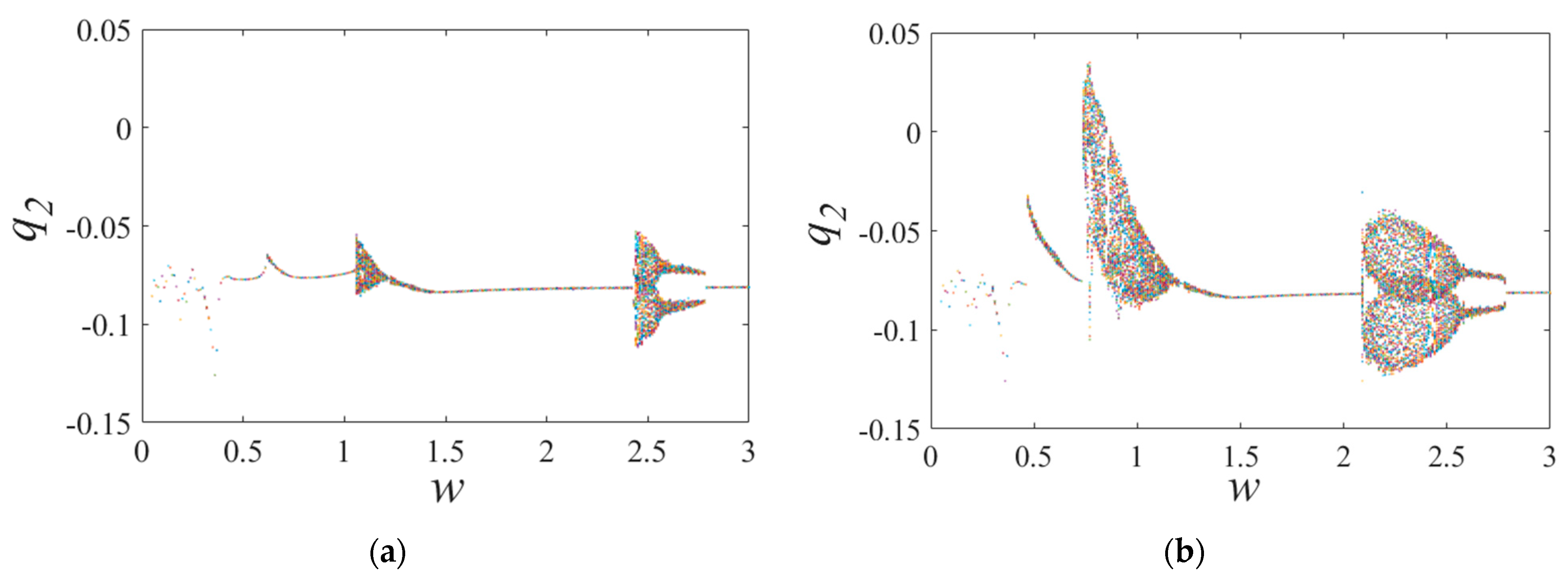
Figure 16 presents bifurcation diagrams of the traditional model, showing the effect of changing the excitation frequency on gear system behavior. These diagrams provide important insights into the system’s nonlinear dynamics and can help identify key differences in behavior under different excitation frequencies that are critical for understanding gear performance. The excitation frequencies shown in Figure 16a,b differ in their range and order of increase and decrease, and together they illustrate the behavior of the gear system over a broad range of excitation frequencies. In particular, the ranges of excitation frequency between 0.42–1.28 and 2.06–2.79 are of significant interest, as they demonstrate the diverse and complex bifurcation characteristics of the gear system under these conditions. Compared to the bifurcation characteristics in Figure 16a, those in Figure 16b show higher complexity, indicating that gear system behavior becomes more diverse as excitation frequency decreases.
In Figure 17, bifurcation diagrams of the traditional model are displayed with varying excitation frequencies. It is evident that the bifurcation characteristics of the traditional and proposed models differ, implying that the gear pair’s meshing position has a significant influence on nonlinear dynamic response.
Severe wear of the gear pair can have significant implications for gear performance, and the bifurcation diagrams presented in Figure 18 can shed light on how the system behaves under these conditions. The motion states of the traditional and proposed models differ in several areas of the bifurcation diagram, suggesting potentially significant differences in gear system behavior under different operating conditions. In Figure 18a, the gear system is in a quasi-periodic motion in the regions of 0.59–0.72, 0.94–1.48, and 2.53–2.81. In contrast, in Figure 18b, the gear system is in a quasi-periodic motion only in the regions of 0.64–0.72 and 2.48–2.87 and changes between quasi-periodic and periodic motion at other frequencies. The changing behavior of the gear system observed in Figure 18b suggests a potentially complex dynamic response, which may indicate increased sensitivity to initial conditions or unstable operating regimes.
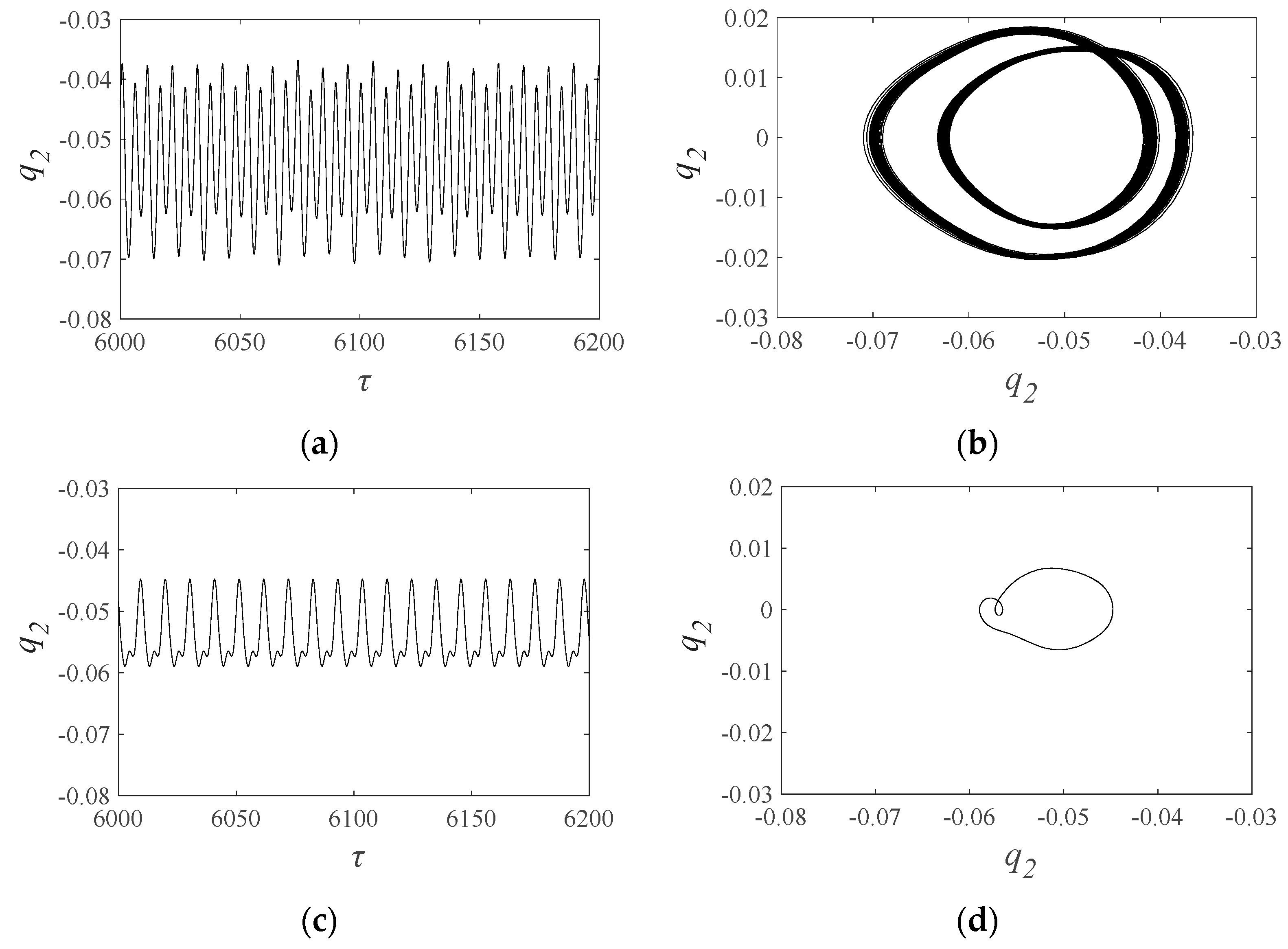
In Figure 19, the motion state is depicted. Figure 19a,b exhibit quasi-periodic motion, while Figure 19c,d exhibit periodic motion. The amplitude of the time series in Figure 19a is notably greater than that in Figure 19c, and the wave patterns in Figure 19a are more intricate than those in Figure 19c. Additionally, there are more trajectories in Figure 19b than in Figure 19d.
Figure 20 displays the time series for the traditional and proposed models under severe wear conditions. It is evident from both Figure 20a,b that the response is quasi-periodic. However, it is worth noting that the amplitude of the time series in Figure 20b is both larger and more complex than that in Figure 20a, indicating a more intricate motion state. In contrast to traditional models, the proposed model accounts for the meshing position and allows for a more accurate prediction of the system’s response.
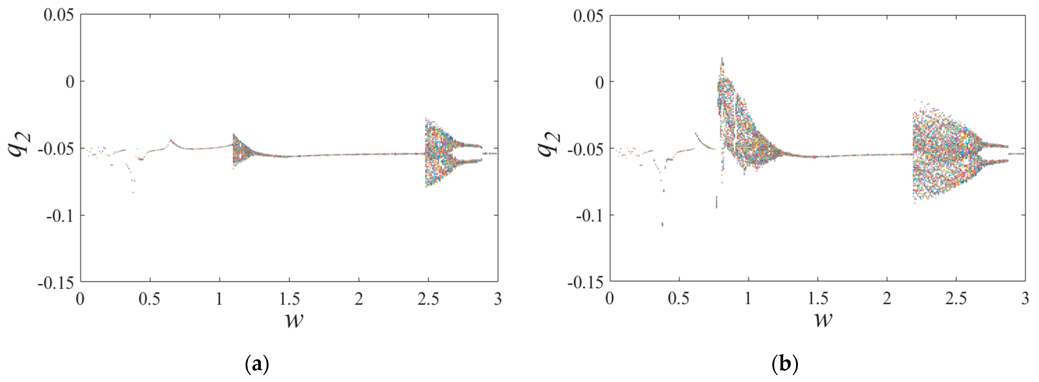
The bifurcation diagrams presented in Figure 21 and Figure 22 are critical for understanding gear performance under conditions of severe wear, and they build upon the findings presented in Figure 16 and Figure 17. Compared to the diagrams presented in Figure 16 and Figure 17, it is clear that the bifurcation characteristics of the gear system change significantly under severe wear conditions. Specifically, the motion state becomes more changeable and the bifurcation characteristics are more complex, particularly when the excitation frequency decreases. Additionally, Figure 21 and Figure 22 illustrate important differences in the bifurcation characteristics of the gear system that can be attributed to the influence of meshing position on the nonlinear dynamic response.
4. Conclusions
- (1)
- This paper presents a novel nonlinear dynamic model with six degrees of freedom that considers the effects of uniform wear on the contact ratio, meshing stiffness, and gear backlash, with wear volume obtained based on the Archard theory. A significant innovation of this work is its consideration of the change in meshing position with wear.
- (2)
- This paper analyzes the nonlinear dynamic characteristics of a gear pair under conditions of no wear, medium wear, and severe wear, using a range of analysis techniques such as bifurcation diagrams, spectrum waterfall diagrams, Poincaré maps, FFT spectra, phase diagrams, and time series with excitation frequency as a control parameter. The results reveal that the dynamic responses of the gear system differ significantly under different degrees of wear.
- (3)
- When the excitation frequency decreases, the bifurcation characteristics of the gear pair are more complex than those when the excitation frequency increases. When the gear teeth are under the different wear conditions, the bifurcation diagrams present different characteristics as the excitation frequency increases or decreases.
- (4)
- The study revealed that the bifurcation characteristics of the gear pair become more complex as the excitation frequency decreases. This suggests that the nonlinear dynamic behavior of gear systems is highly dependent on the excitation frequency and can exhibit significantly different characteristics at different excitation frequencies. Furthermore, the study demonstrated that the bifurcation diagrams observed under varying degrees of gear wear when the excitation frequency varies also present different characteristics.
Author Contributions
Conceptualization, Z.G.; methodology, Z.G. and M.C.; software, Z.G. and J.W.; validation, Y.X., Y.K. and K.X.; formal analysis, Z.G.; investigation, Y.X.; resources, Y.K.; data curation, J.W.; writing—original draft preparation, Z.G.; writing—review and editing, M.C. and J.W.; visualization, Y.X.; supervision, M.C.; funding acquisition, Z.G., Y.K. and J.W. All authors have read and agreed to the published version of the manuscript.
Funding
This research was funded by [National Natural Science Foundation of China] grant number [52105108, 52375039].
Data Availability Statement
No new data were created or analyzed in this study.
Conflicts of Interest
The authors declare no conflict of interest.
References
- Kahraman, A. Load sharing characteristics of planetary transmissions. Mech. Mach. Theory 1994, 29, 1151–1165. [Google Scholar] [CrossRef]
- Jian, L.; Parker, R.G. Analytical Characterization of the Unique Properties of Planetary Gear Free Vibration. J. Vib. Acoust.-Trans. ASME 1999, 121, 316–321. [Google Scholar]
- Yu, X.; Sun, Y.; Li, H.; Wu, S. Nonlinear characteristics of gear pair considering fractal surface dynamic contact as internal excitation. Int. J. Non-Linear Mech. 2022, 143, 104027. [Google Scholar] [CrossRef]
- Yi, G.; Parker, R.G. Dynamic Analysis of Planetary Gears With Bearing Clearance. J. Comput. Nonlinear Dyn. 2012, 7, 041002. [Google Scholar]
- Farshidianfar, A.; Saghafi, A. Global bifurcation and chaos analysis in nonlinear vibration of spur gear systems. Nonlinear Dyn. 2014, 75, 783–806. [Google Scholar] [CrossRef]
- Sheng, L.; Li, W.; Wang, Y.; Fan, M.; Yang, X. Nonlinear dynamic analysis and chaos control of multi-freedom semi-direct gear drive system in coal cutters. Mech. Syst. Signal Proc. 2019, 116, 62–77. [Google Scholar] [CrossRef]
- Huang, K.; Cheng, Z.; Xiong, Y.; Han, G.; Li, L. Bifurcation and chaos analysis of a spur gear pair system with fractal gear backlash. Chaos Solitons Fractals 2020, 142, 110387. [Google Scholar] [CrossRef]
- Wang, S.; Zhu, R. Nonlinear dynamic analysis of GTF gearbox under friction excitation with vibration characteristics recognition and control in frequency domain. Mech. Syst. Signal Proc. 2021, 151, 107373. [Google Scholar] [CrossRef]
- Wang, J.; Liu, N.; Wang, H.; Guo, L. Research on bifurcation and chaos characteristics of planet gear transmission system with mixed elastohydrodynamic lubrication (EHL) friction. Int. J. Nonlinear Sci. Num. 2021. [Google Scholar] [CrossRef]
- Tunalioğlu, M.Ş.; Tuç, B. Theoretical and experimental investigation of wear in internal gears. Wear 2014, 309, 208–215. [Google Scholar] [CrossRef]
- Pei, J.; Han, X.; Tao, Y.; Feng, S. Study on Wear Dynamic Reliability of Gear System Based on Markov Diffusive Process. J. Tribol. 2022, 144, 021202. [Google Scholar] [CrossRef]
- Xiang, G.; Yang, T.Y.; Guo, J.; Wang, J.X. Optimization transient wear and contact performances of water-lubricated bearings under fluid-solid-thermal coupling condition using profile modification. Wear 2022, 502–503, 204379. [Google Scholar] [CrossRef]
- Chang, L.; Jeng, Y.R.; Huang, P.Y. Modeling and Analysis of the Meshing Losses of Involute Spur Gears in High-Speed and High-Load Conditions. J. Tribol. 2012, 135, 011504. [Google Scholar] [CrossRef]
- Simon, V.V. Multi-objective optimization of hypoid gears to improve operating characteristics. Mech. Mach. Theory 2020, 146, 103727. [Google Scholar] [CrossRef]
- Li, X.; Xu, J.; Yang, Z.; Chen, R.; Yang, H. The influence of tooth surface wear on dynamic characteristics of gear-bearing system based on fractal theory. J. Comput. Nonlinear Dyn. 2020, 15, 041004. [Google Scholar] [CrossRef]
- Tang, D.X.; Xiang, G.; Guo, J. On the optimal design of staved water-lubricated bearings driven by tribo-dynamic mechanism. Phys. Fluids 2023, 35, 093611. [Google Scholar] [CrossRef]
- Meng, F.S.; Xia, H.; Zhang, X.; Wang, J.X. A new tooth pitting modeling method based on matrix equation for evaluating time-varying mesh stiffness. Eng. Fail. Anal. 2022, 142, 106799. [Google Scholar] [CrossRef]
- Li, B.; Li, P.; Zhou, R.; Feng, X.; Zhou, K. Contact mechanics in tribological and contact damage-related problems: A review. Tribol. Int. 2022, 171, 107534. [Google Scholar] [CrossRef]
- Saini, V.; Maurya, U.; Thakre, G.D. Estimating the Dry-Wear Behavior of Rolling/Sliding Bearings (PB, Gunmetal, and Al6061)–Tribo Materials. J. Fail. Anal. Prev. 2023, 23, 2439–2451. [Google Scholar] [CrossRef]
- Zhang, B.; Liu, H.; Zhu, C.; Ge, Y. Simulation of the fatigue-wear coupling mechanism of an aviation gear. Friction 2021, 9, 1616–1634. [Google Scholar] [CrossRef]
- Yuksel, C.; Kahraman, A. Dynamic tooth loads of planetary gear sets having tooth profile wear. Mech. Mach. Theory 2004, 39, 695–715. [Google Scholar] [CrossRef]
- Archard, J.F. Contact and rubbing of flat surfaces. J. Appl. Phys. 1953, 24, 981–988. [Google Scholar] [CrossRef]
- Shen, Z.; Qiao, B.; Yang, L.; Lou, W.; Yang, Z. Fault mechanism and dynamic modeling of planetary gear with gear wear. Mech. Mach. Theory 2021, 155, 104098. [Google Scholar] [CrossRef]
- Zhan, Y.; Smith, W.; Borghesani, P.; Randall, R.; Peng, Z.X. Absolute transmission error: A simple new tool for assessing gear wear. Mech. Syst. Signal Proc. 2021, 146, 107070. [Google Scholar]
- Zhang, X.; Zhong, J.; Li, W.; Mateusz, B. Nonlinear dynamic analysis of high-speed gear pair with wear fault and tooth contact temperature for a wind turbine gearbox. Mech. Mach. Theory 2022, 173, 104840. [Google Scholar] [CrossRef]
- Koffi, D.; Kassegne, K.A.; Wotodzo, K.F.; Bedja, K. Modeling and Prediction of Mechanical Behavior of Plastic Gears in Simulated Wear Situation. Solid State Phenom. 2012, 188, 232–237. [Google Scholar] [CrossRef]
- Feng, S.; Mao, J.; Xie, Y. Analysis and Calculation of Gear Mesh Stiffness with Tooth Wear. Chin. J. Mech. Eng. 2015, 51, 27–32. [Google Scholar] [CrossRef]
- Zhou, C.; Wang, H. An adhesive wear prediction method for double helical gears based on enhanced coordinate transformation and generalized sliding distance model. Mech. Mach. Theory 2018, 128, 58–83. [Google Scholar] [CrossRef]
- Geng, Z.; Xiao, K.; Wang, J.; Li, J. Investigation on Nonlinear Dynamic Characteristics of a New Rigid–Flexible Gear Transmission with Wear. J. Vib. Acoust.-Trans. ASME 2019, 14, 051008. [Google Scholar] [CrossRef]
- Sheng, L.; Li, W.; Ye, G.; Feng, K. Nonlinear dynamic analysis of gear system in shearer cutting section under wear failure. Proc. Inst. Mech. Eng. K J. Multi-Body Dyn. 2022, 236, 99–112. [Google Scholar] [CrossRef]
- Geng, Z.; Xiao, K.; Li, J.; Wang, J. Bifurcation and Chaos of a Spur Gear Transmission System With Non-Uniform Wear. J. Vib. Acoust.-Trans. 2020, 143, 031004. [Google Scholar] [CrossRef]
- Chen, Z.; Zhou, Z.; Zhai, W.; Wang, K. Improved analytical calculation model of spur gear mesh excitations with tooth profile deviations. Mech. Mach. Theory 2019, 149, 103838. [Google Scholar] [CrossRef]
- Cao, Z.; Shao, Y.; Rao, M.; Yu, W.N. Effects of the gear eccentricities on the dynamic performance of a planetary gear set. Nonlinear Dyn. 2018, 91, 1–15. [Google Scholar] [CrossRef]
- Xie, C.Y.; Hua, L.; Han, X.H.; Lan, J.; Wan, X.J.; Xiong, X.S. Analytical formulas for gear body-induced tooth deflections of spur gears considering structure coupling effect. Int. J. Mech. Sci. 2018, 148, 174–190. [Google Scholar] [CrossRef]
Figure 1.
Results of theoretical analysis of gear wear depth by Shen et al. [Reproduced with permission from Shen et al.; published by ELSEVIER, 2021] [23].
Figure 1.
Results of theoretical analysis of gear wear depth by Shen et al. [Reproduced with permission from Shen et al.; published by ELSEVIER, 2021] [23].

Figure 2.
Experimental observation results of wear depth of gears by Zhan et al. [Reproduced with permission from Zhan et al.; published by ELSEVIER, 2021] [24].
Figure 2.
Experimental observation results of wear depth of gears by Zhan et al. [Reproduced with permission from Zhan et al.; published by ELSEVIER, 2021] [24].

Figure 3.
The model of the gear pair.

Figure 4.
The diagram of the gear with wear.

Figure 5.
The uniform cantilever beam model of the spur gear tooth with uniform wear.
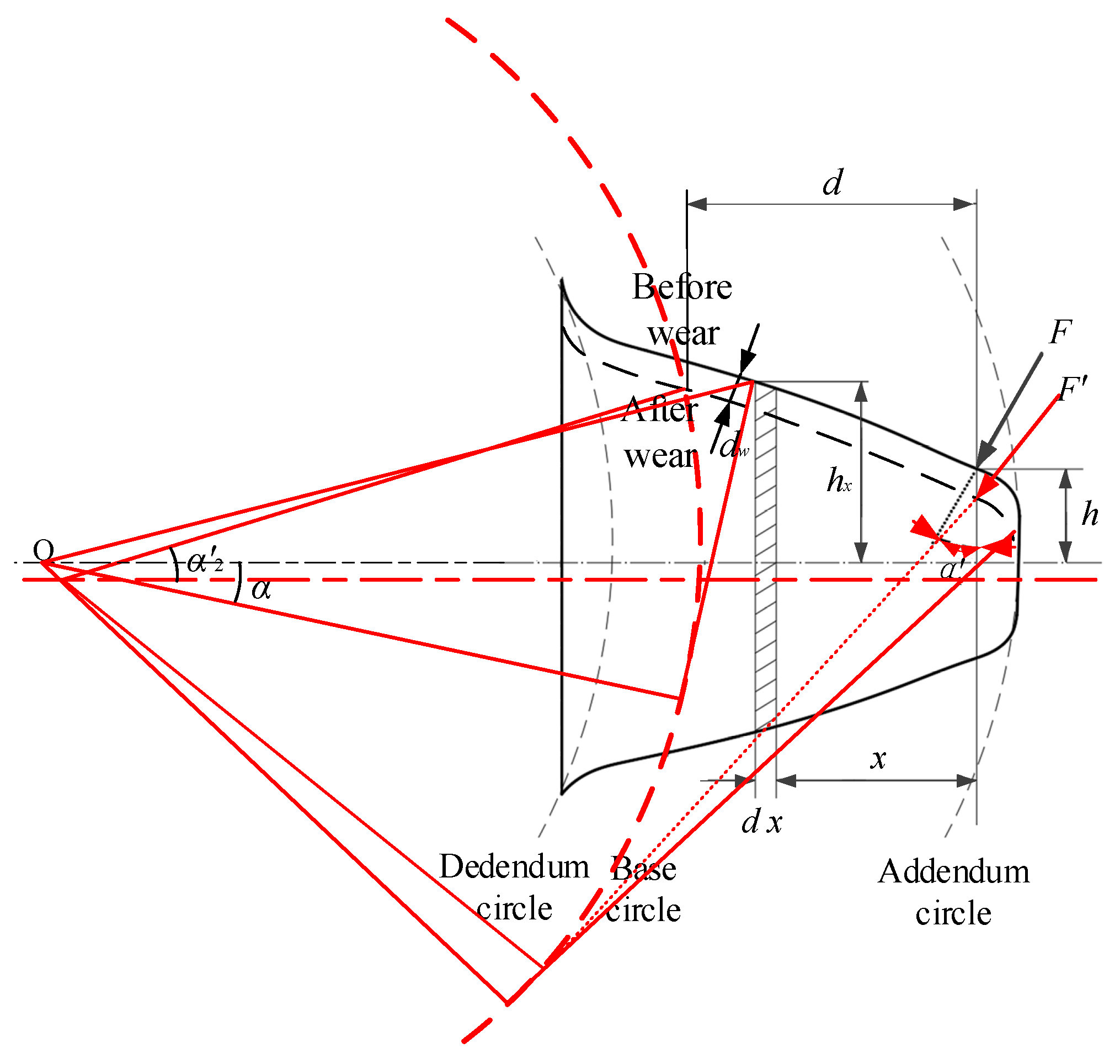
Figure 6.
Flowchart of the proposed dynamic model with non-uniform surface wear.

Figure 7.
Meshing stiffness of the gear pair with wear: (a) proposed model; (b) traditional model.
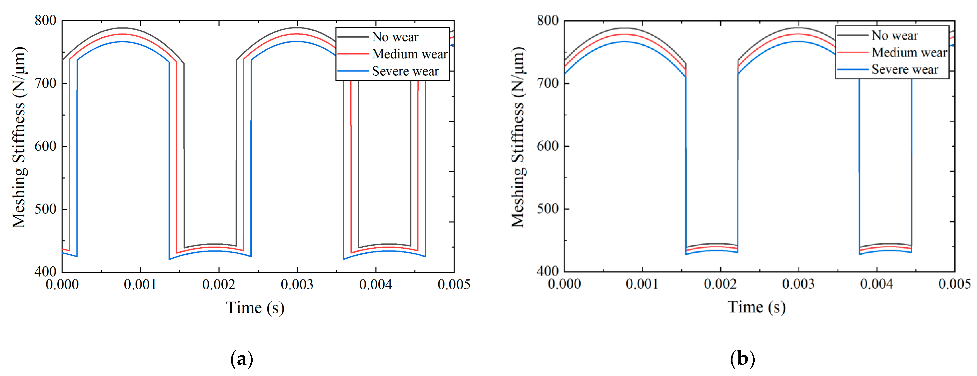
Figure 8.
(a) Bifurcation diagram and (b) spectrum waterfall diagram at different excitation frequencies without wear.
Figure 8.
(a) Bifurcation diagram and (b) spectrum waterfall diagram at different excitation frequencies without wear.
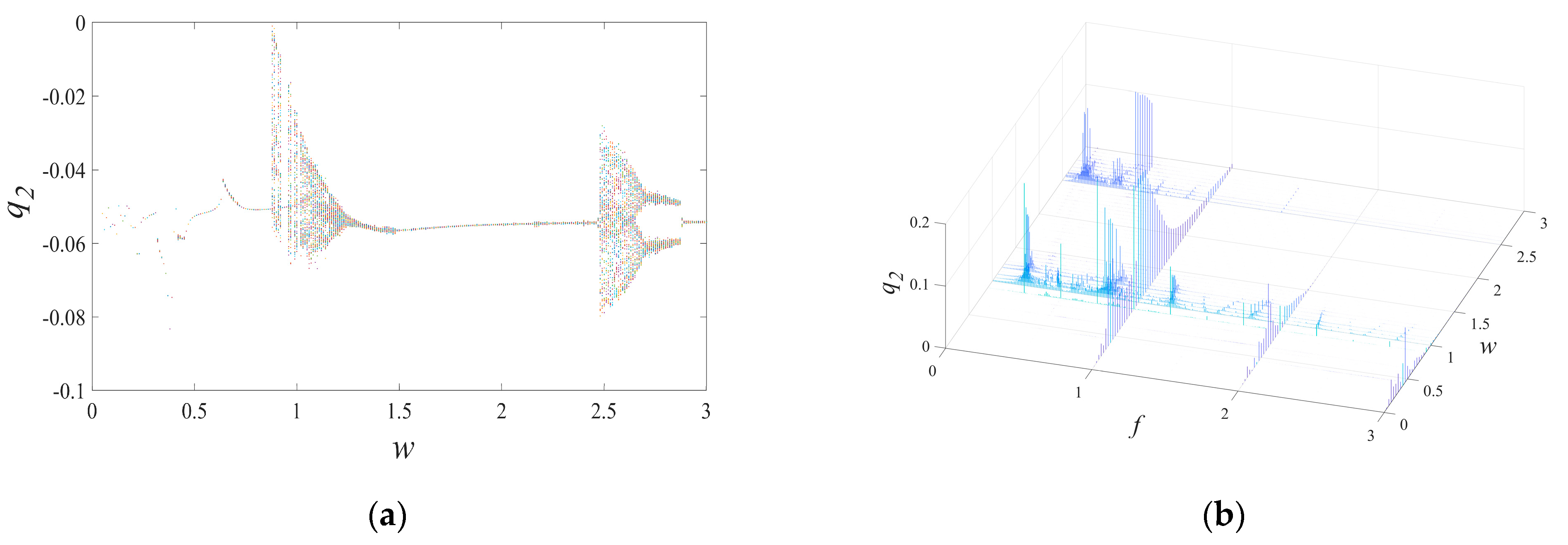
Figure 9.
(a) Time series, (b) phase diagram, (c) Poincaré map, and (d) FFT spectrum when excitation frequencies are 0.6.
Figure 9.
(a) Time series, (b) phase diagram, (c) Poincaré map, and (d) FFT spectrum when excitation frequencies are 0.6.

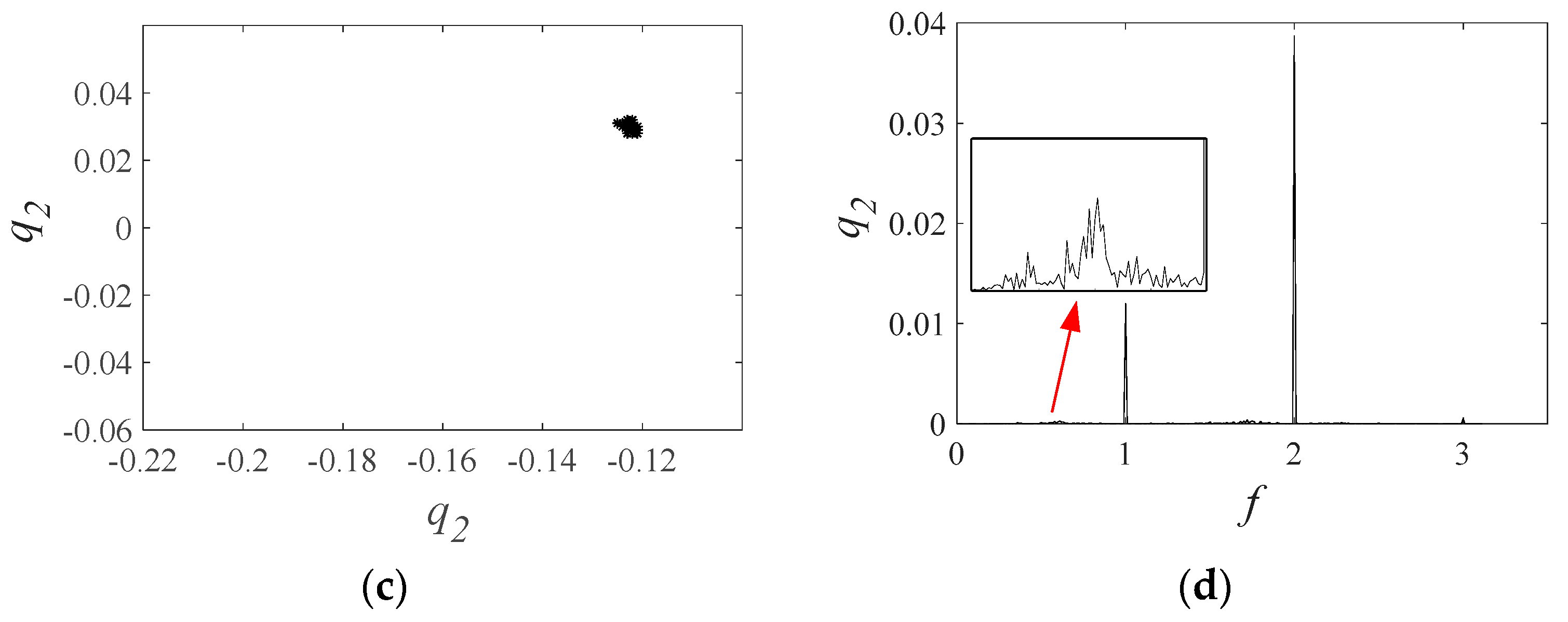
Figure 10.
(a) Time series, (b) phase diagram, (c) Poincaré map, and (d) FFT spectrum when excitation frequencies are 0.8.
Figure 10.
(a) Time series, (b) phase diagram, (c) Poincaré map, and (d) FFT spectrum when excitation frequencies are 0.8.
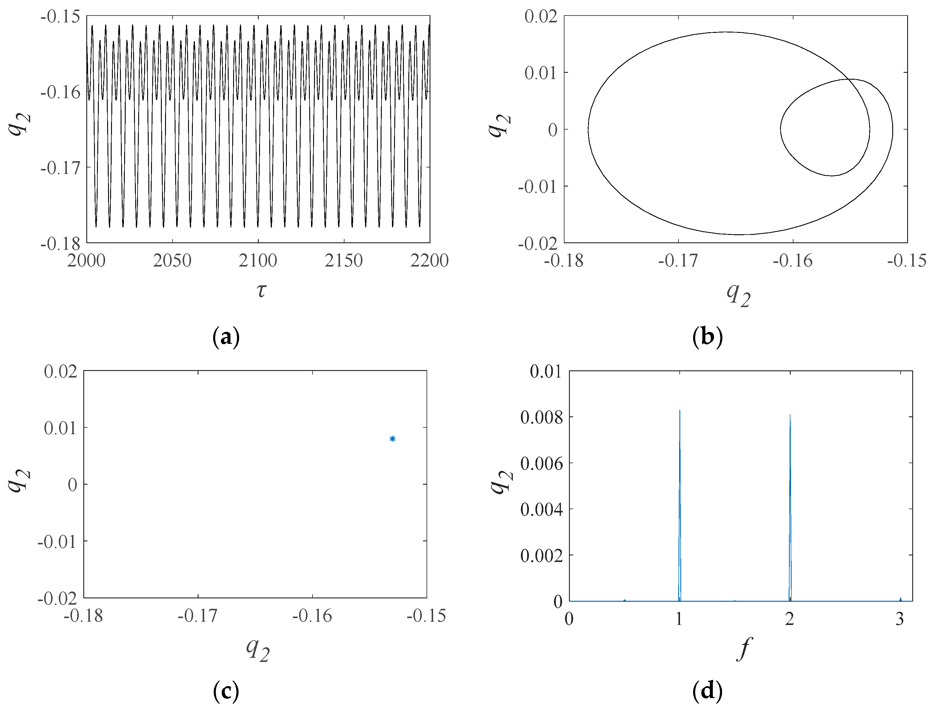
Figure 11.
(a) Time series, (b) phase diagram, (c) Poincaré map, and (d) FFT spectrum when excitation frequencies are 1.1.
Figure 11.
(a) Time series, (b) phase diagram, (c) Poincaré map, and (d) FFT spectrum when excitation frequencies are 1.1.
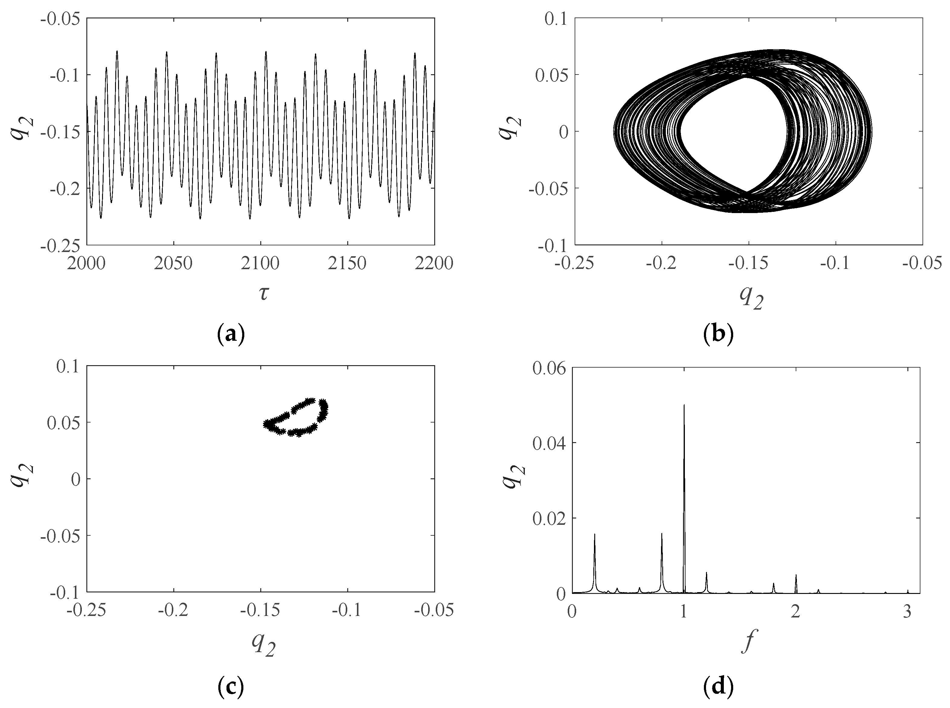
Figure 12.
(a) Poincaré map; (b) FFT spectrum when excitation frequencies is 2.7.
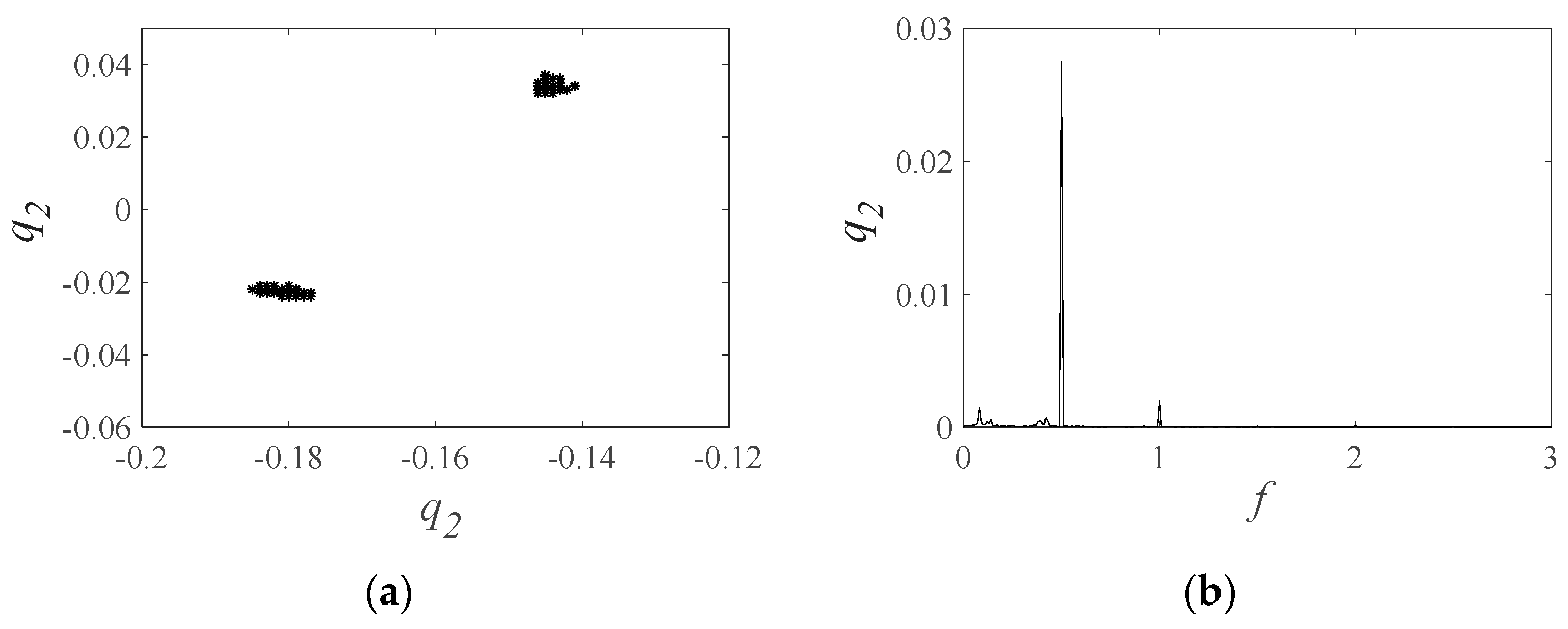
Figure 13.
Bifurcation diagrams with medium wear: (a) tranditional model; (b) proposed model.

Figure 14.
(a) Phase diagram and Poincaré map; (b) FFT spectrum of the traditional model; (c) phase diagram and Poincaré map; (d) FFT spectrum of the proposed model with medium wear when the excitation frequency is 0.96.
Figure 14.
(a) Phase diagram and Poincaré map; (b) FFT spectrum of the traditional model; (c) phase diagram and Poincaré map; (d) FFT spectrum of the proposed model with medium wear when the excitation frequency is 0.96.

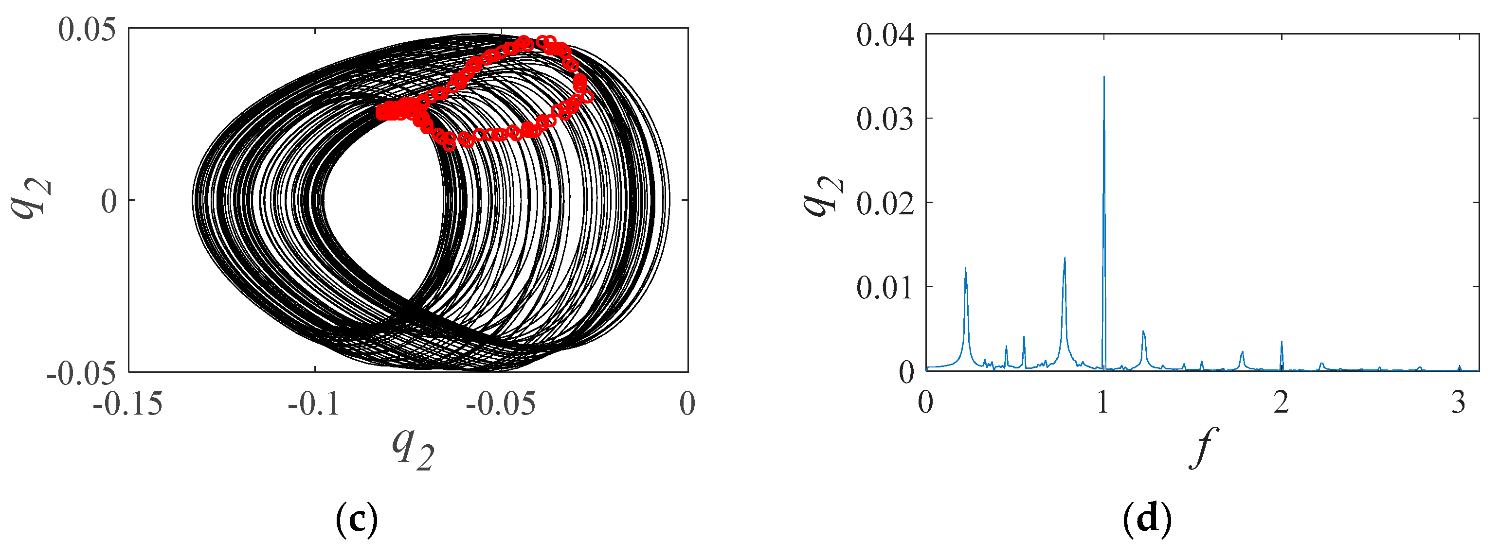
Figure 15.
Phase diagram and Poincaré map of the gear pair: (a) traditional model; (b) proposed model.
Figure 15.
Phase diagram and Poincaré map of the gear pair: (a) traditional model; (b) proposed model.
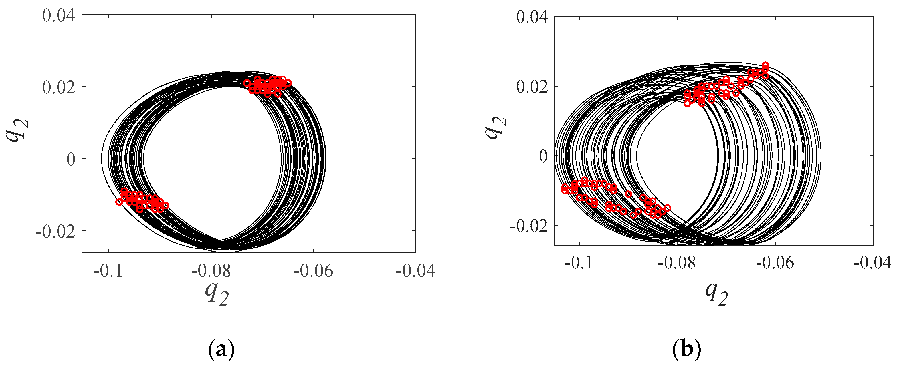
Figure 16.
Bifurcation diagrams of the traditional model with medium wear. (a) w increases and (b) w decreases.
Figure 16.
Bifurcation diagrams of the traditional model with medium wear. (a) w increases and (b) w decreases.

Figure 17.
Bifurcation diagrams of the proposed model with medium wear. (a) w increases and (b) w decreases.
Figure 17.
Bifurcation diagrams of the proposed model with medium wear. (a) w increases and (b) w decreases.

Figure 18.
Bifurcation diagrams with severe wear: (a) traditional model and (b) proposed model.

Figure 19.
(a) Time series and (b) phase diagram of the traditional model, and (c) time series and (d) phase diagram of the proposed model with the severe wear when the excitation frequency is 0.6.
Figure 19.
(a) Time series and (b) phase diagram of the traditional model, and (c) time series and (d) phase diagram of the proposed model with the severe wear when the excitation frequency is 0.6.

Figure 20.
Time series of the gear pair with the severe wear: (a) traditional model and (b) proposed model.
Figure 20.
Time series of the gear pair with the severe wear: (a) traditional model and (b) proposed model.
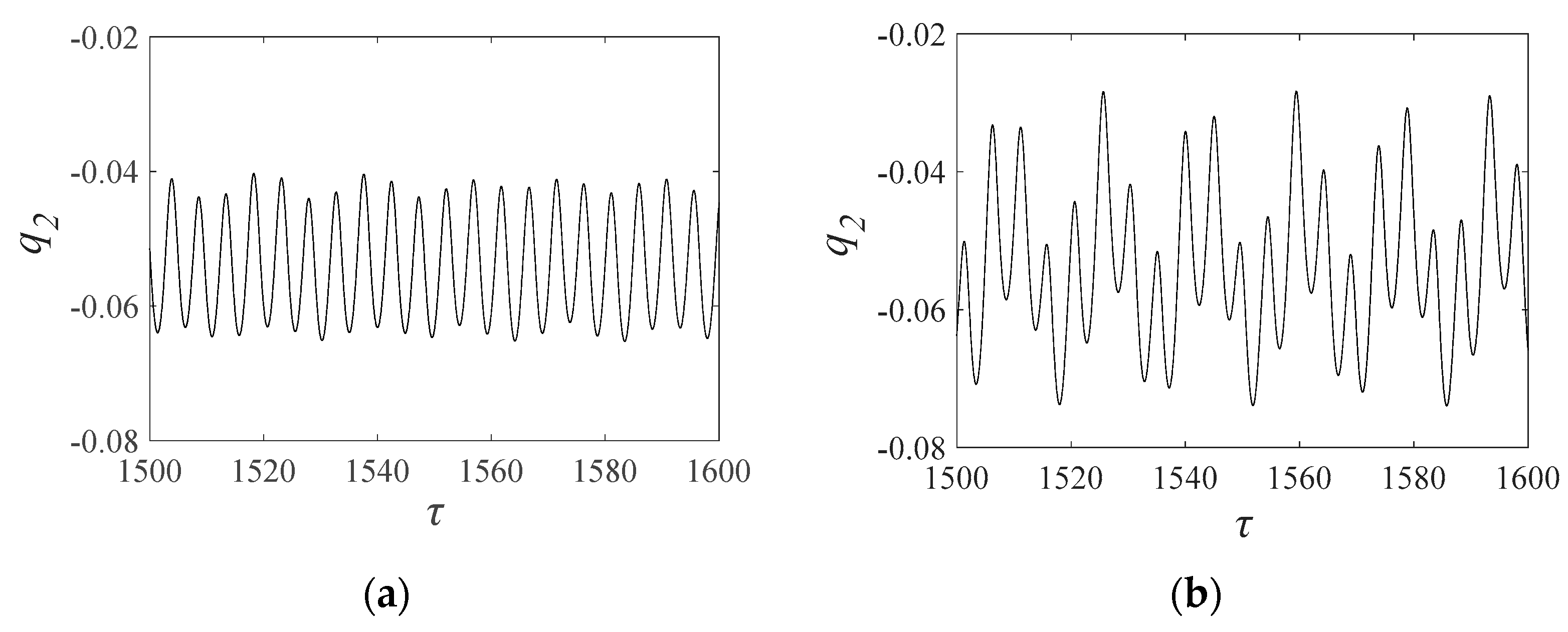
Figure 21.
Bifurcation diagrams of the traditional model with severe wear. (a) w increases and (b) w decreases.
Figure 21.
Bifurcation diagrams of the traditional model with severe wear. (a) w increases and (b) w decreases.
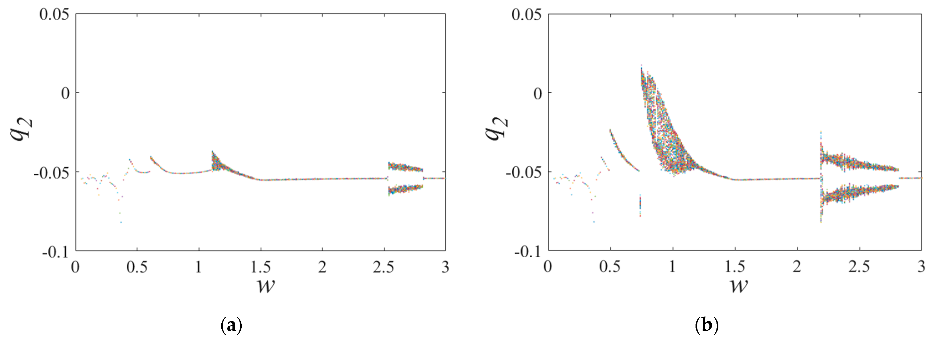
Figure 22.
Bifurcation diagrams of the proposed model with severe wear. (a) w increases and (b) w decreases.
Figure 22.
Bifurcation diagrams of the proposed model with severe wear. (a) w increases and (b) w decreases.

Table 1.
Parameters of the gear pair.
| Driving Gear | Driven Gear | |
|---|---|---|
| Number of teeth | 27 | 55 |
| Modulus (mm) | 2.5 | |
| Pressure angle | 20° | |
| Mass (kg) | 0.584 | 2.007 |
| Diameter of the shaft bore (mm) | 35 | 35 |
| Rotation inertia (kg/m2) | 0.00043 | 0.005487 |
| Contact ratio | 1.7002 | |
| Initial Gear backlash (μm) | 50 | |
Disclaimer/Publisher’s Note: The statements, opinions and data contained in all publications are solely those of the individual author(s) and contributor(s) and not of MDPI and/or the editor(s). MDPI and/or the editor(s) disclaim responsibility for any injury to people or property resulting from any ideas, methods, instructions or products referred to in the content. |
© 2024 by the authors. Licensee MDPI, Basel, Switzerland. This article is an open access article distributed under the terms and conditions of the Creative Commons Attribution (CC BY) license (https://creativecommons.org/licenses/by/4.0/).
Share and Cite
MDPI and ACS Style
Geng, Z.; Chen, M.; Wang, J.; Xia, Y.; Kong, Y.; Xiao, K. Nonlinear Dynamic Analysis of a Spur Gear Pair System with Wear Considering the Meshing Position. Lubricants 2024, 12, 25. https://doi.org/10.3390/lubricants12010025
AMA Style
Geng Z, Chen M, Wang J, Xia Y, Kong Y, Xiao K. Nonlinear Dynamic Analysis of a Spur Gear Pair System with Wear Considering the Meshing Position. Lubricants. 2024; 12(1):25. https://doi.org/10.3390/lubricants12010025
Chicago/Turabian StyleGeng, Zhibo, Min Chen, Jiao Wang, Yu Xia, Yun Kong, and Ke Xiao. 2024. "Nonlinear Dynamic Analysis of a Spur Gear Pair System with Wear Considering the Meshing Position" Lubricants 12, no. 1: 25. https://doi.org/10.3390/lubricants12010025
Note that from the first issue of 2016, this journal uses article numbers instead of page numbers. See further details here.