Study on Grease Lubrication and Electric Erosion Characteristics in AC Electric Fields


1
School of Mechanical and Automotive Engineering, Qingdao University of Technology, Qingdao 266520, China
2
Department of Mechanical Engineering, City University of Hong Kong, Tat Chee Avenue, Kowloon, Hong Kong SAR, China
3
Lanzhou Institute of Chemical Physics, Chinese Academy of Sciences, Lanzhou 730030, China
4
Qingdao Zhongke Runmei Lubrication Material Technology Co., Ltd., Qingdao 266100, China
*
Author to whom correspondence should be addressed.
Lubricants 2024, 12(3), 79; https://doi.org/10.3390/lubricants12030079
Submission received: 31 January 2024
/
Revised: 24 February 2024
/
Accepted: 1 March 2024
/
Published: 4 March 2024
(This article belongs to the Special Issue Tribological Study in Rolling Bearing)
Abstract
:Protecting motor bearings from electric erosion is crucial as electric vehicles evolve. To better understand how lubrication interacts with electric discharge within motor bearings during varying speeds of vehicle operation, an optical ball-on-disk tribometer was modified to investigate the influence of alternating current (AC) electric fields on film thickness, friction force under various lubrication regions, and discharge characteristics. The study revealed that in AC electric fields, as the lubrication state shifts from mixed lubrication to fluid lubrication region, the electrical characteristic of the lubricating oil film changes from resistive to capacitive, accompanied by an increase in discharge frequency. Under the elastohydrodynamic lubrication (EHL) region, an electrical potential difference between the surfaces separated by the lubrication film leads to a reduction in film thickness, which can be attributed to the generation of Joule heating. If the potential difference across the oil film increases to the threshold voltage, destructive discharge occurs with the emission of a significant amount of purple light. Joule heating generated by the AC electric fields also results in a reduction in the friction coefficient under the fluid lubrication region. However, due to the reduction in film thickness, the lubrication state eventually moves to mixed lubrication, leading to a substantial increase in the friction coefficient. In addition, the study also investigated the use of grease with a nanographite conductive additive. It was found that inappropriate additive amounts can lead to discharge phenomena occurring outside the contact region.
1. Introduction
The drive motor stands as the nucleus of electric vehicles, and its service life and reliability have a pivotal influence on the performance of the car. The extensive application of pulse width modulation (PWM) technology and insulate-gate bipolar transistor (IGBT) components in drive motors has accentuated the prominence of electrical erosion damage in bearing failures, constituting a formidable issue that demands careful consideration [1,2].
When the motor is driven by a PWM inverter, the switching dynamics of power devices induce fluctuations in the common-mode voltage. This common-mode voltage establishes a potential difference between the inner and outer races of the motor bearings [3]. Beyond the threshold, the potential difference across the oil film results in the breakdown of the film, giving rise to a substantial transient current known as an electric discharge machining (EDM) current. This occurrence leads to consequential damage to the rolling elements and raceway surfaces [4]. In scenarios where the potential difference remains below the threshold voltage, the contact area can be analogously regarded as a capacitor. The alternating common-mode voltage continually charges and discharges the oil film capacitor, generating a current referred to as dV/dt current [5]. This current, acting over an extended period, leads to damage to the bearing tracks and greases. Additionally, magnetic asymmetries in the rotor can create a low-frequency rotor voltage, discharging across bearings [6]. The occurrence of bearing damage induced by electrical currents is denoted as “electric erosion” [7,8]. The adverse effects of electric erosion predominantly manifest as fluting [9,10], frosting, and the formation of electric pitting craters [11]. Concurrently, the generation of bearing current heightens the susceptibility to bearing failure due to white etching crack (WEC) [12]. Typically, issues related to electric erosion contribute to the degradation of noise–vibration–harshness (NVH) characteristics in electric vehicles [10] and, in severe instances, may result in motor malfunctions. Hence, there exists an imperative need to undertake comprehensive research into electric erosion.
Substantial efforts have been made to address the issue of bearing electrical erosion. Noguchi et al. [13] demonstrated that electric erosion can occur in 608 bearings even at a current density as low as 0.04 A/mm2. Esmaeili et al. [14] investigated the electric discharge behavior for steel-to-steel contact under various test conditions, revealing that discharge between steel rollers is influenced by oil film thickness and contact area. Plazenet et al. [2] confirmed through bench testing that voltage, bearing temperature, and grease type can affect the level of electrical corrosion and, consequently, the life of electric motor bearings. Muetze [15] investigated the influence of factors such as motor design, operational parameters, and the interconnection between the motor and inverter on bearing current, proposing potential mitigating strategies. Graf [16], focusing on thrust bearings, determined that the breakdown voltage is contingent upon variables such as oil film thickness, load, and current frequency. Gonda et al. [17] conducted experimental investigations on a bench scale to elucidate the impact of grease conductivity on bearing currents. Turnbull et al. [18] presented an inclusive multiphysics model based on motor bearings, proficient in forecasting the onset of fluting in bearings. Bleger et al. [19] employed a combined experimental and numerical approach to study discharge behavior in motor bearings. Sunahara et al. [11] employed a camera to capture electrical discharge occurring between the ball and the glass disk. They also observed that the threshold value of voltage with oil film breakdown increases with an increase in oil film thickness. Suzumura [20] demonstrated that conductive greases can reduce the current density in the contact area, thereby preventing the formation of “fluting” on the bearing raceways. Zhang et al. [21] used carbon black as an additive to formulate conductive grease and confirmed enhancements in the grease’s electrical conductivity and antifriction and antiwear properties. Guo et al. [22] conducted electric discharge experiments at the steel ball-steel disk interface, confirming the relationship between discharge behavior and oil film thickness. Schneider et al. [8] presented a comprehensive overview from the standpoint of motor drive systems, summarizing the latest research findings regarding bearing currents.
Simultaneously, researchers have also delved into the failure modes of greases under electrical environments, and some failure mechanisms of greases were revealed, for example, degradation, microbubble formation, and so on [23]. Prashad [24] found that local currents can cause greases to decompose and can even cause carbonization. Romanenko et al. [25] also revealed that discharge currents can generate high-viscosity substances in the greases that are detrimental to lubrication and can lead to additive agglomeration. Luo et al. [26], using a ball-to-disk test rig, discovered for the first time that lubricants can form microbubbles under an applied electrical field. Xie et al. [27,28,29] found that microbubbles are a result of local overheating. Under the influence of surface tension gradients, these microbubbles migrate outward from the contact point, and lubricants containing microbubbles are more susceptible to electrical breakdown.
During the operation of electric vehicles, the adjustment of driving speed in response to varying road conditions is essential. This dynamic scenario exposes motor bearings to different lubrication states. However, few have been directly observed to undergo variations in film thickness and discharge characteristics across different lubrication regions under AC electric field environments. Therefore, the authors updated an optical ball-on-disk tribometer by constructing an electrical voltage across the oil film to study the lubrication states of grease under the influence of AC electric fields. Additionally, conductive greases, with nanographite as the conductive additive, were measured to initiate a preliminary exploration of the crucial factors involved in formulating conductive grease with conductive particles as additives.
2. Experiment
2.1. Experimental Apparatus
The experiment was conducted on an optical ball-on-disk tribometer(Qingdao GreenLub Times Advanced Lubrication Technology Co, Ltd, Qingdao, China), the detailed structure of which is depicted in Figure 1. Two independent servomotors are used to control the speeds of the steel ball and the glass disk separately, allowing for the various slide–roll ratios. A semireflecting chromium (Cr) layer of 20 nm thickness was deposited onto the working surface of the glass disk. In order to reduce the resistance between contacting surfaces, the Cr layer was covered with an indium tin oxide (ITO) film of 300 nm thickness [11,30], thereby reducing the resistance to approximately 13 Ω. The steel ball, which is insulated from its driving shaft by insulating paper, was fastened in position with a plastic bolt. The glass disk and the steel ball were interconnected through an alternating current power supply, creating a comprehensive circuit. The alternating current power supply emitted a sinusoidal wave with a frequency of 50 Hz.
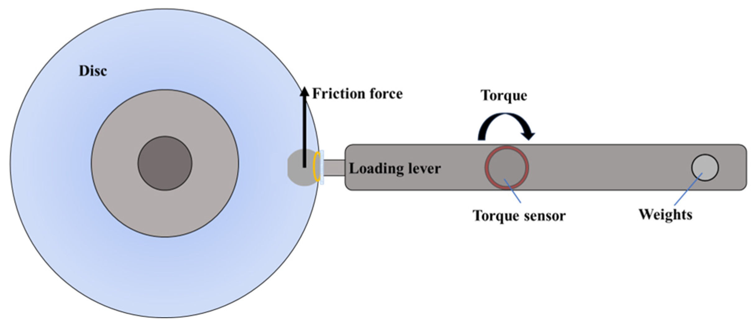
Dichromatic laser lights (red and green) were injected into the contact to obtain interferograms. These interferograms were captured by a camera of charge coupled device (CCD). The film thickness was measured by dichromatic interference intensity modulation (DIIM) technology [31]. Friction forces were measured at different slide–roll ratios, as illustrated in Figure 2. The surface morphology of the steel ball was examined using the German Leica DM 1750 M microscope (Leica Microsystems GmbH, Wetzlar, Germany) to analyze damage under various lubrication conditions.
2.2. Experimental Conditions
The ball used in the optical test is of G5 grade and made of AISI52100 steel with a diameter of 25.4 mm, and the disk is of K9 glass with a diameter of 150 mm. The experimental conditions are presented in Table 1, where ξ represents the slide–roll ratio, , and and are the linear velocities of the glass disk and steel ball at the contact, respectively.
The experiment employed two greases. The first, designated as G-A, is a lithium-based grease with a base oil mixture of polyalphaolefin oil (PAO10) and diester oil (diisodecyl adipate), and it contains lithium 12-hydroxystearate as the thickener. The second, identified as G-B, represented a conductive grease derived from G-A through the addition of a 0.2% mass fraction of nanographite. The composition of the two grease samples is detailed in Table 2. Furthermore, a V-shaped grease collector was used to ensure sufficient grease supply. In the experiment, this collector was employed to collect grease from the side ridges and guide it to the central lubrication track.
3. Results and Discussion
3.1. Variations in Oil Film Thickness in Different Lubrication Regions
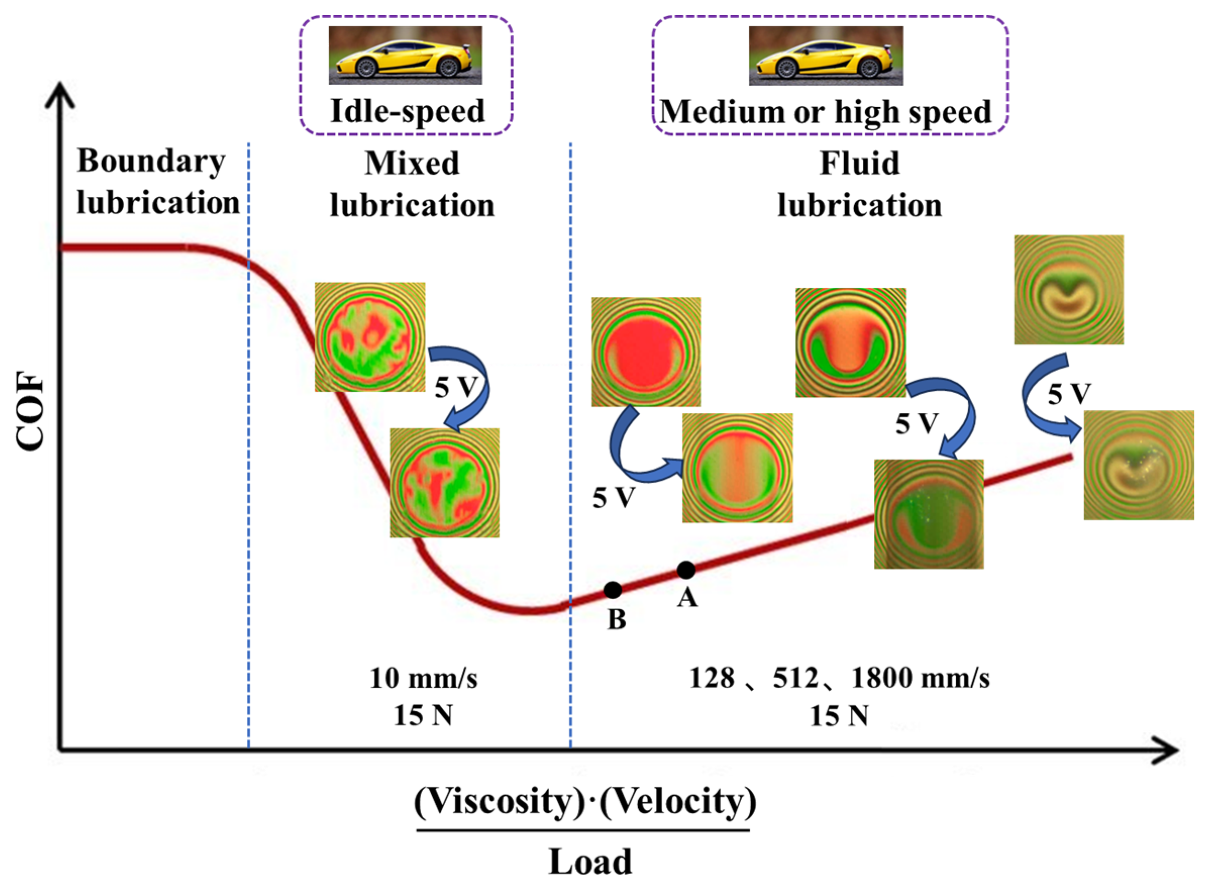
With a load of 15 N, a series of tests were conducted at entrainment speeds of 10 mm/s, 128 mm/s, 512 mm/s, and 1800 mm/s to simulate the lubrication states of motor bearings in electric vehicles under conditions of idle, medium-speed, and high-speed driving scenarios. For each entrainment speed, the experiment ran at 0 V for 30 min, followed by the application of a 5 V sinusoidal alternating voltage for an additional 30 min. Subsequently, another 30 min operation at 0 V was performed. The lubrication state and interferograms are illustrated in Figure 3 and Figure 4. At an entrainment speed of 10 mm/s, the contact region exhibited a mixed lubrication state, while at 128 mm/s and 512 mm/s, it entered typical EHL. However, at 1800 mm/s, the EHL state faded away, and the lubrication began to develop toward hydrodynamic lubrication because the characteristics of the horseshoe oil film became less obvious.
Figure 4a reveals that in the mixed lubrication region, the thickener in the grease entered into the contact, actively contributing to lubrication. This phenomenon was evident as irregular green and red areas appeared in the interferograms. Upon the application of a 5 V AC electric field, there was no discernible change in the interferogram and, therefore, no change in the lubrication state. Following a 30 min operation, there was no evident damage observed on the surfaces of the contact.
When the lubrication state moved to EHL, as depicted in Figure 4b,c, the application of a 5 V AC voltage gradually reduced the oil film thickness. Simultaneously, sporadic discharge phenomena occurred, resulting in surface damage to the contact surface. At an entrainment speed of 128 mm/s, after operating for 30 min in the AC electric field, subtle electric-erosion-induced damage was vaguely discerned on the glass disk surface (indicated by the black arrow in Figure 4b). At an entrainment speed of 512 mm/s, distinct discharge flashes in the contact region could be observed, intensifying the damage to the glass disk. Furthermore, it was noteworthy that upon removing the electric field, the oil film thickness gradually increased, and at 128 mm/s, it could even go back to its initial value.
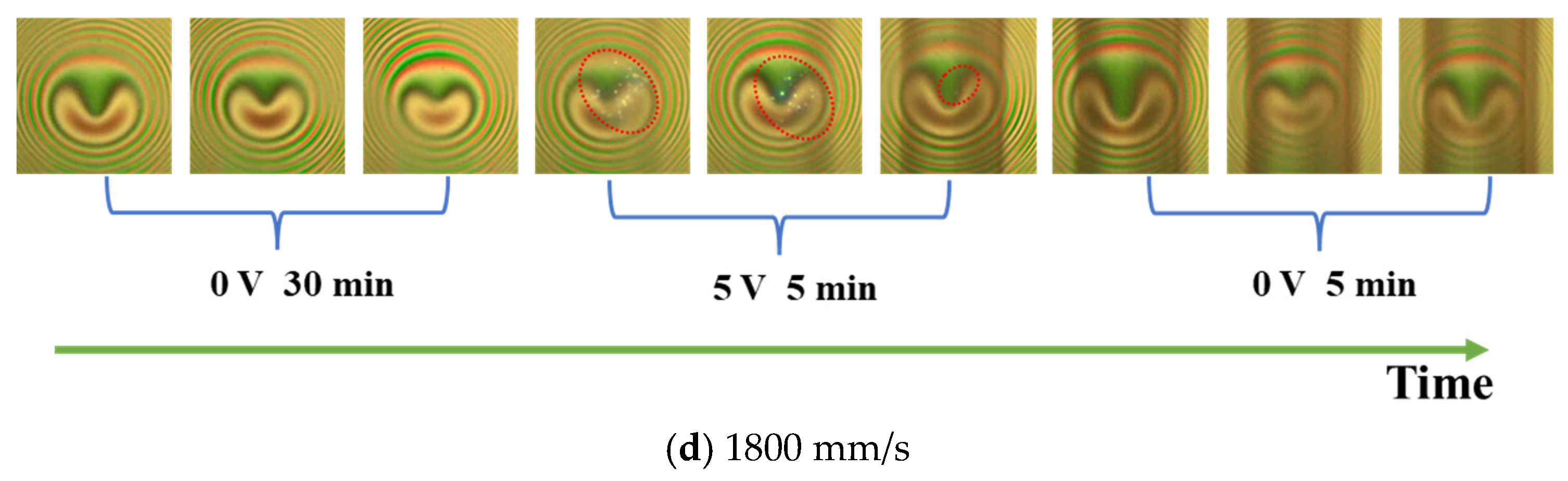
When the entrainment speed was 1800 mm/s, as depicted in Figure 4d, the oil film thickness further increased. The discharge flash, captured by the CCD camera, exhibited a heightened density, and the discharge occurred more frequently with an elevation in film thickness. In the meantime, it was revealed that the flash’s location predominantly concentrated on the region with the minimum film thickness, which is attributed to the fact that the electric field is at its strength peak at the minimum film thickness and is more susceptible to discharges.
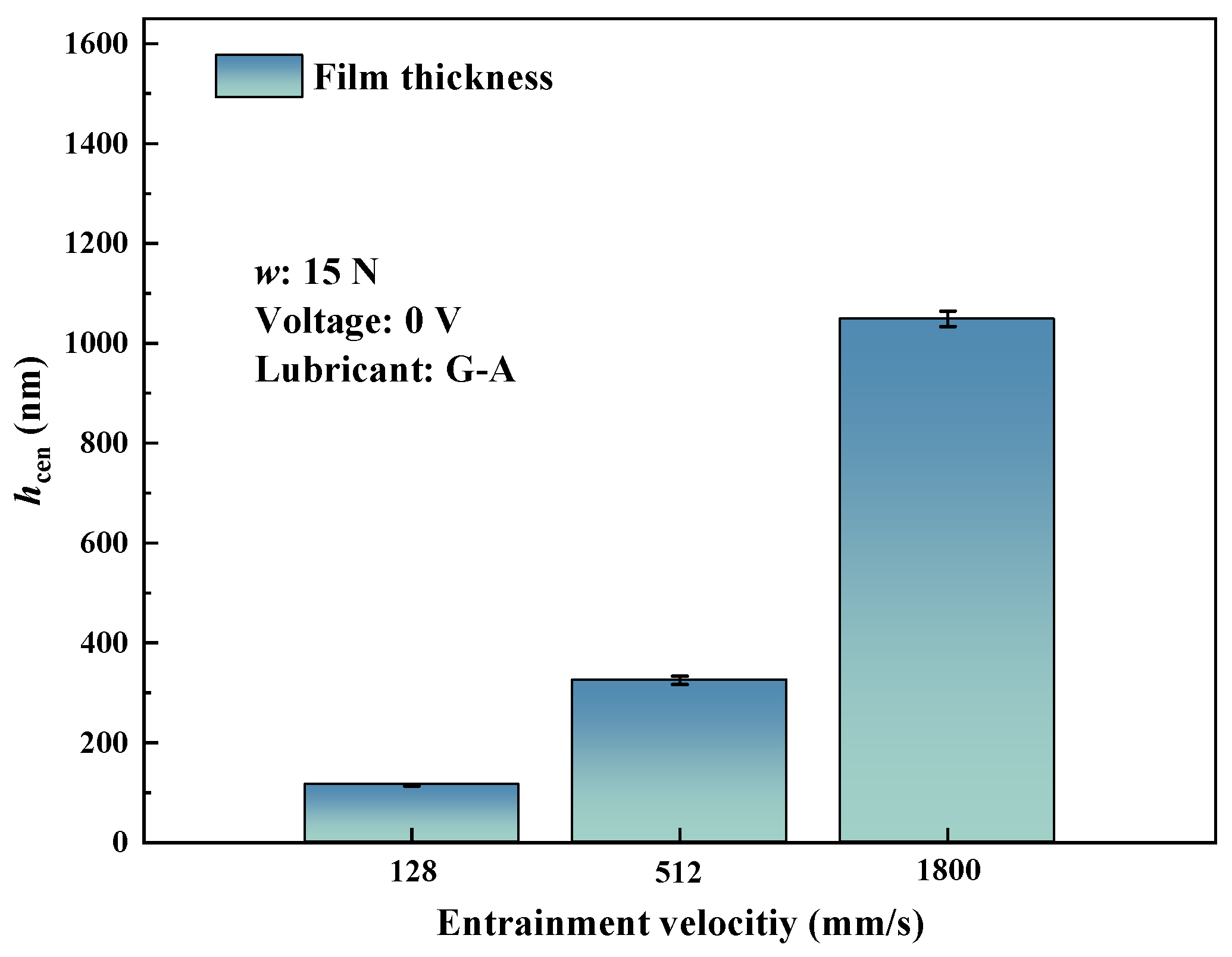
To further observe the damage by discharges on the surfaces of the steel ball, microscopic examinations were conducted. The findings, with the oil film thickness at three speeds, are delineated in Figure 5 and Figure 6. It was found that at lower entrainment speeds, corresponding to smaller oil film thickness, the incidence of discharges within the contact was minimal, resulting in minor damage to the steel ball surface. As the entrainment speed increased to 512 mm/s, the damage to the steel ball surface became more pronounced. When the entrainment speed further increased (1800 mm/s), the oil film thickness became higher. The high-frequency discharges gave rise to more severe electrically induced pitting on the steel ball surface. Furthermore, the steel ball surface at the minimum oil film thickness revealed more severe electric damage compared with other regions. This concurred with the observed phenomenon in the interferograms, where discharges were predominantly concentrated on the area of minimum film thickness.
In order to further quantify the influence of the AC electric fields, a measured film thickness of 128 mm/s was plotted against the test time, as shown in Figure 7. The figure reveals that, due to the implementation of a grease collector ensuring sufficient grease supply, the oil film thickness remained stable at approximately 117 nm before the application of the 5 V AC electric field (0~1800 s). Following the introduction of the electric field between the ball–disk pair, the oil film thickness gradually decreased over time. After 3600 s, the oil film thickness reduced to 39 nm. Upon the removal of the AC electric field, the oil film thickness gradually reverted.
The above results indicated that under the mixed lubrication region, the presence of an AC electric field has no discernible impact on lubrication. During this phase, the contact region consistently underwent contacts between rough peaks, leading to minimal resistance in the ball–disk contact area. No discharge phenomena were observed, and the contact maintained a state of electrical conductivity [32].
In the EHL state, when the potential difference across the oil film was given, discharge could be observed in the contact, and a reduction in oil film thickness appeared. With the removal of the potential difference, the oil film thickness gradually reverted. As we know, the EHL contact can be treated as a parallel combination of oil film resistance and a parallel capacitor [32]. In this state, the resistance is relatively high, leading to significant Joule heating as current flows. Simultaneously, the formation of microbubbles occurs. These microbubbles migrate outward by uneven temperature and surface tension distribution in the contact [25,26,30]. Microbubbles generated in the electric field displace the lubricant near the contact area, and the directional movement of microbubbles also hinders the flow of lubricant back into the contact area, leading to a reduction in oil film thickness. Fundamentally, the generation, movement, and rupture of microbubbles disrupt the stability of lubrication [28]. Joule heating also results in reduced lubricant viscosity and deteriorates film-forming capability.
When the oil film thickness was at a higher level, the oil film resistance attained an exceptionally high value, and the contact was more similar to a pure capacitor. During this phase, the oil film achieved considerable thickness, accompanied by a relatively small capacitance value. Consequently, it became highly susceptible to discharge breakdown when subjected to AC electric fields, leading to the observation of more densely distributed discharge flashes in the interferograms.
In conclusion, with the transition of the lubrication state from mixed lubrication to fluid lubrication, there was an increase in oil film thickness. The ball-on-disk contact underwent a shift from a resistive to a capacitive state. As the film thickness increased, the capacitance value decreased, rendering it more susceptible to discharge breakdown. Consequently, higher oil film thickness resulted in a more pronounced occurrence of discharge flashes.
3.2. Discharge Characteristics under EHL
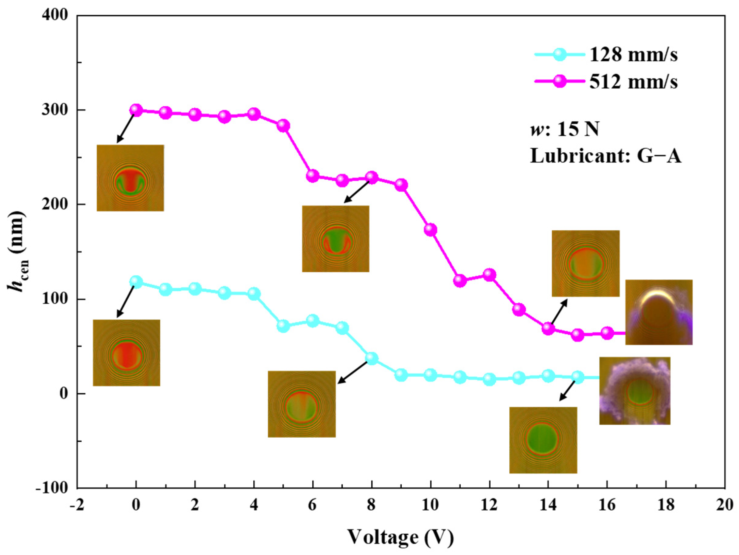
To further investigate the discharge characteristics in the EHL region, interferograms were captured under continuously varying voltage conditions. The experiment was conducted under a 15 N load with sufficient grease supply at two entrainment speeds: 128 mm/s and 512 mm/s. The procedure was initiated with a voltage of 0 V and increased incrementally by 1 V every 30 s until destructive electrical discharge took place in the contact. The findings are elucidated in Figure 8. The figure reveals that within the lower voltage range (0~4 V), the oil film thickness exhibited a relatively small variation. However, with voltage increase, the oil film thickness gradually decreased. For example, at an entrainment speed of 128 mm/s, the oil film thickness decreased from 105 nm at 4 V to 17 nm at 15 V with an 83.8% reduction. With further voltage increase, the potential difference across the oil film reached a threshold, resulting in sustained discharge throughout the contact. This type of discharge, distinct from the sporadic discharge discussed in Section 3.1, manifested as a persistent and extensive one accompanied by a purple light, referred to as destructive discharge. This phenomenon culminated in the complete destruction of the conductive layer on the glass disk, prompting the termination of the experiment.
Figure 9a,b depict the images of discharge under two entrainment speeds, along with the morphological damage on the surfaces of the glass disk and the steel ball surfaces. It was evident that at 128 mm/s, the destructive discharge produced a substantial amount of purple light, almost enveloping the entire Hertzian contact region. Microscopic examination showed that the coating on the surface of the glass disk was entirely destroyed, leaving distinct electrical erosion marks on the surface of the steel ball. At 512 mm/s, the discharge frequency increased after reaching the threshold, leading to more severe damage to the steel ball.
3.3. COFs in Various Lubrication Regions
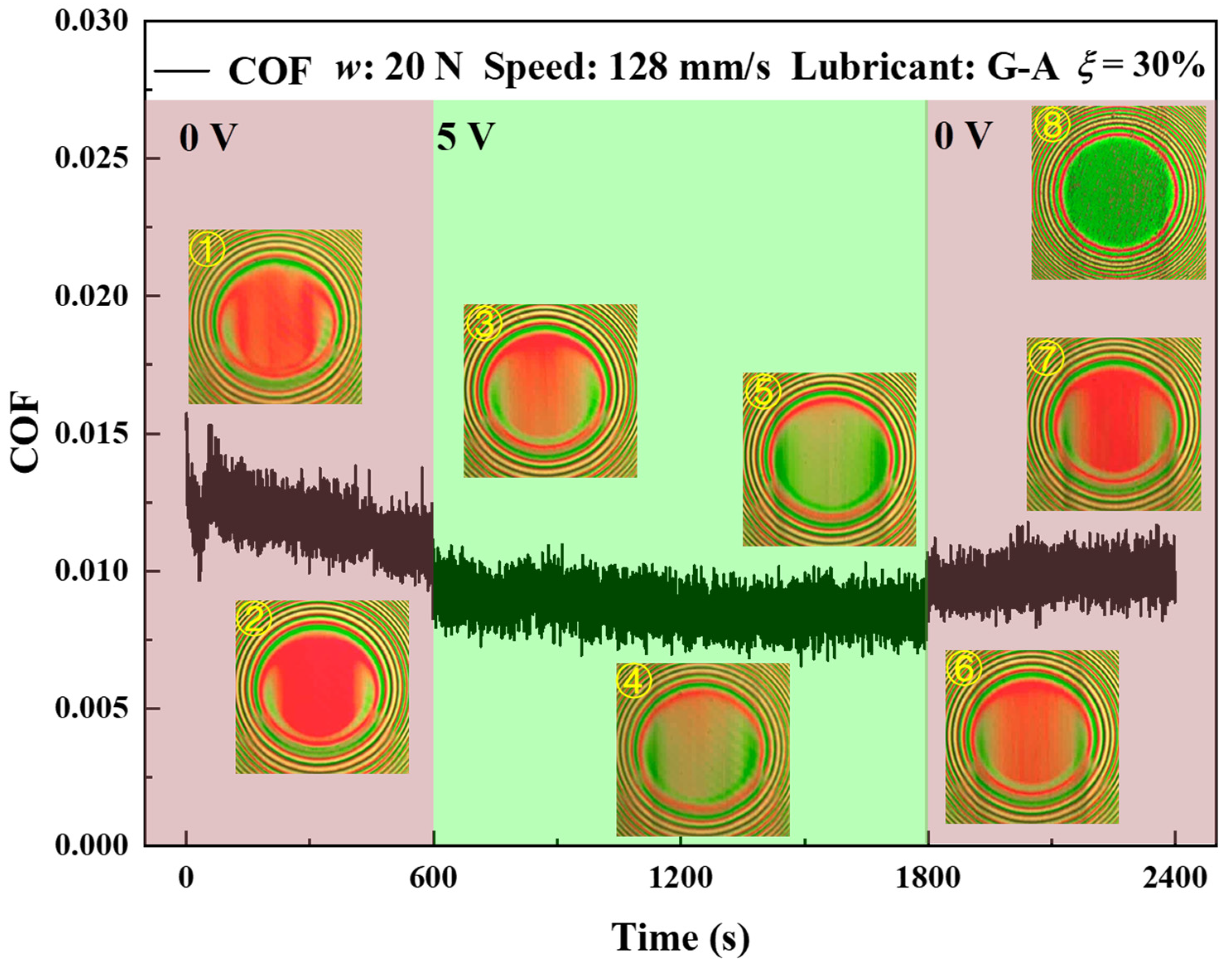
The film thickness ratio, denoted as λ, is often used for estimation of the lubrication state. It is defined as the ratio of average film thickness over composite root mean square (RMS) roughness. When 1 < λ < 3, the system resides in mixed lubrication, while λ > 3 indicates fluid lubrication, encompassing both EHL and hydrodynamic lubrication. Figure 10 illustrates the friction coefficient variation for G-A grease under an AC electric field, with a load of 20 N, entrainment speed of 128 mm/s, and a slide–roll ratio of 30% over a 40 min test duration. It can be observed that the application of the AC electric field induced a reduction in oil film thickness and an augmentation in the surface roughness of the contact. Consequently, the λ value decreased, which meant the lubrication state shifted from point A to point B in Figure 3, resulting in a reduction in the friction coefficient. Upon removing the electric field at 1800 s, the oil film thickness experienced an increase, leading to an elevation in the friction coefficient.
Figure 11 illustrates the friction coefficient and interferograms under continuous variable speed conditions within an AC electric field. The experimental setup involved a load of 20 N, a slide–roll ratio of 30%, and cyclically varying entrainment speeds at 512 mm/s, 96 mm/s, and 32 mm/s, each speed running for a duration of 10 min. It was discernible that the application of the AC electric field resulted in decreased oil film thickness and damage to the surfaces of the contact, leading to a fluctuation in the friction coefficient. At 512 mm/s, the friction coefficient mirrored a comparable trend to that observed at 128 mm/s. Nevertheless, a reduction in entrainment speed to 96 mm/s caused a marginal increase in the friction coefficient. Subsequent deceleration to 32 mm/s induced a substantial rise in the friction coefficient, attributed to the contact between rough peaks within the contact. Consequently, these experiments underscored the AC electric field’s efficacy in reducing the friction coefficient in the fluid lubrication region. However, surface damage induced by discharges and the decrease in oil film thickness due to thermal effects ultimately precipitated a transition in the lubrication state toward mixed lubrication, resulting in contact between rough peaks and a noteworthy escalation in the friction coefficient.
3.4. Discharge Characteristics of Graphite-Based Conductive Grease
The authors conducted an investigation into the discharge characteristics of conductive grease (G-B) with nanographite as an additive under the influence of an AC electric field. The experimental parameters included a load of 20 N, a voltage of 5 V, a slide–roll ratio of 30%, and entrainment speeds of 512 mm/s, 96 mm/s, and 32 mm/s, each running for 10 min. As a benchmark, the same test was repeated with G-A grease, which is the base grease of G-B grease. The findings are depicted in Figure 12.
From the interferograms of the two greases in the AC electric field, it is evident that the introduction of a 0.2% mass fraction of nanographite in the grease not only diminished the oil film resistance within the contact but also reduced the resistance of the grease out of the contact region. This decrease in resistance enabled the potential difference out of the contact region to reach the threshold voltage required for discharge phenomena, resulting in surface damage. However, when G-A grease was used, the discharge occurred entirely within the contact area. Furthermore, as graphite particles were drawn into the contact, the coating on the glass disk underwent mechanical wear. In summary, the formulation of conductive grease with nanographite as a conductive additive necessitates rigorous control of the additive’s content, with attention to ensuring that particle size remains within appropriate limits.
4. Conclusions
This paper employed an updated optical ball-on-disk tribometer to replicate the lubrication conditions experienced by motor bearings of electric vehicles at various speeds. The investigation delved into parameters such as oil film thickness, friction coefficient, and discharge characteristics, specifically focusing on scenarios of mixed lubrication and fluid lubrication regions within an AC electric field. Furthermore, the study introduced nanographite into the grease as a conductive additive, aiming to explore the characteristics of graphite-based conductive grease in an electric field. The results indicate:
- (1)
- In an alternating current (AC) electric field, as the lubrication state changes from mixed lubrication to fluid lubrication, the oil film in the ball-on-disk contact area will change from resistive to capacitive, and the higher the film thickness, the smaller the capacitance value, and the higher the frequency of discharge.
- (2)
- Within the EHL region, Joule heating induces a reduction in oil film thickness in the Hertzian contact area. A larger potential difference corresponds to a diminished oil film thickness. Upon the potential difference reaching the threshold voltage, destructive discharge occurs, accompanied by the emergence of a significant quantity of purple light.
- (3)
- An AC electric field can reduce the friction coefficient in a fluid lubrication region. However, surface damage induced by discharges and the decrease in oil film thickness due to thermal effects ultimately precipitates a transition in the lubrication state toward mixed lubrication, resulting in contact between rough peaks and a noteworthy escalation in the friction coefficient.
- (4)
- When formulating conductive grease with nanographite as a conductive additive, a higher mass fraction of the additive can instigate discharges beyond the contact area. Furthermore, it is imperative to control the particle size, as an overly large size may lead to abrasive particle wear.
Author Contributions
Conceptualization, F.G. and Z.L.; methodology, Z.L.; validation, Z.J., B.L., X.W. and L.Z.; investigation, Z.L., X.W. and F.G.; writing—original draft preparation, Z.L.; writing—review and editing, Z.L. and F.G. All authors have read and agreed to the published version of the manuscript.
Funding
This research was funded by the Natural Science Foundation of China (No. 52175173) and Shandong Zhilian Community Bearing Technology Co., Ltd. (KF-0084).
Data Availability Statement
The data that support the findings of this study are available from the corresponding author upon reasonable request.
Conflicts of Interest
The authors declare that they have no known competing financial interests or personal relationships that could have appeared to influence the work reported in this paper.
References
- He, F.; Xie, G.; Luo, J. Electrical bearing failures in electric vehicles. Friction 2020, 8, 4–28. [Google Scholar] [CrossRef]
- Plazenet, T.; Boileau, T.; Caironi, C.C.; Nahid-Mobarakeh, B. Influencing parameters on discharge bearing currents in inverter-fed induction motors. IEEE Trans. Energy Convers. 2021, 36, 940–949. [Google Scholar] [CrossRef]
- Isomura, Y.; Yamamoto, K.; Morimoto, S.; Maetani, T.; Watanabe, A.; Nakano, K. Study of the further reduction of shaft voltage of brushless DC motor with insulated rotor driven by PWM inverter. IEEE Trans. Ind. Appl. 2014, 50, 3738–3743. [Google Scholar] [CrossRef]
- Plazenet, T.; Boileau, T.; Caironi, C.; Nahid-Mobarakeh, B. A comprehensive study on shaft voltages and bearing currents in rotating machines. IEEE Trans. Ind. Appl. 2018, 54, 3749–3759. [Google Scholar] [CrossRef]
- Muetze, A.; Binder, A. Don’t lose your bearings. IEEE Ind. Appl. Mag. 2006, 12, 22–31. [Google Scholar] [CrossRef]
- Raymond, O. An Investigation of Shaft Current in a Large Sleeve Bearing Induction Machine. Ph.D. Thesis, McMaster University, Hamilton, ON, Canada, 1999. [Google Scholar]
- Niu, K.; Song, C.; Lou, Z.; Pang, X.; Lu, H.; Du, S.; Zhao, Y. Electric damage of bearing under AC shaft voltage at different rotation speeds. Tribol. Int. 2023, 177, 108008. [Google Scholar]
- Schneider, V.; Behrendt, C.; Höltje, P.; Cornel, D.; Becker-Dombrowsky, F.M.; Puchtler, S.; Kirchner, E. Electrical bearing damage, a problem in the nano-and macro-range. Lubricants 2022, 10, 194. [Google Scholar] [CrossRef]
- Boyanton, H.E.; Hodges, G. Bearing fluting [motors]. IEEE Ind. Appl. Mag. 2002, 8, 53–57. [Google Scholar] [CrossRef]
- Wouter, O.; Patrick, D.B. Failure analysis of the deep groove ball bearings of an electric motor. Eng. Fail. Anal. 2005, 12, 772–783. [Google Scholar]
- Sunahara, K.; Yamashita, S.; Yamamoto, M.; Ikeda, M.; Nishikawa, H.; Matsuda, K.; Kaneta, M. Development of grease film breakdown observing device. Tribol. Online 2008, 3, 40–43. [Google Scholar] [CrossRef]
- López-Uruñuela, F.J.; Fernandez-Diaz, B.; Pagano, F.; López-Ortega, A.; Pinedo, B.; Bayón, R.; Aguirrebeitia, J. Broad review of “White Etching Crack” failure in wind turbine gearbox bearings: Main factors and experimental investigations. Int. J. Fatigue 2021, 145, 106091. [Google Scholar] [CrossRef]
- Noguchi, S.; Korenaga, A.; Kanada, T. Occurrence condition of electric current density in electrical pitting (in case of ball bearing 608 for application of direct current). J. Adv. Mech. Des. Syst. Manuf. 2010, 4, 469–479. [Google Scholar] [CrossRef]
- Esmaeili, K.; Wang, L.; Harvey, T.J.; White, N.M.; Holweger, W. Electrical discharges in oil-lubricated rolling contacts and their detection using electrostatic sensing technique. Sensors 2022, 22, 392. [Google Scholar] [CrossRef] [PubMed]
- Muetze, A. Bearing Currents in Inverter-Fed AC-Motors. Ph.D. Thesis, TU Darmstadt, Darmstadt, Germany, 2003. [Google Scholar]
- Graf, S.; Werner, M.; Koch, O.; Götz, S.; Sauer, B. Breakdown voltages in thrust bearings behavior and measurement. Tribol. Trans. 2023, 8, 11. [Google Scholar] [CrossRef]
- Gonda, A.; Capan, R.; Bechev, D.; Sauer, B. The influence of lubricant conductivity on bearing currents in the case of rolling bearing greases. Lubricants 2019, 7, 108. [Google Scholar] [CrossRef]
- Turnbull, R.; Rahmani, R.; Paul, S.; Rahnejat, H. Electrotribodynamics of ball bearings in electrical machines. Tribol. Int. 2023, 188, 108817. [Google Scholar] [CrossRef]
- Bleger, A.; Leighton, M.; Morris, N. Automotive e-motor bearing electrical discharge phenomena: An experimental and numerical investigation. Tribol. Int. 2024, 191, 109140. [Google Scholar] [CrossRef]
- Suzumura, J. Prevention of electrical pitting on rolling bearings by electrically conductive grease. Q. Rep. RTRI 2016, 57, 42–47. [Google Scholar] [CrossRef]
- Zhang, P.L.; Wang, G.G.; Zhao, Y.J.; Wu, H.; Xia, Y.Q. Study of conductive and friction properties of grease containing carbon black additive. Adv. Mat. Res. 2015, 1120, 586–589. [Google Scholar] [CrossRef]
- Guo, L.; Mol, H.; Nijdam, T.; Vries, L.D.; Bongaerts, J. Study on the electric discharge behaviour of a single contact in EV motor bearings. Tribol. Int. 2023, 187, 108743. [Google Scholar] [CrossRef]
- Chen, Y.; Jha, S.; Raut, A.; Zhang, W.Y.; Liang, H. Performance characteristics of lubricants in electric and hybrid vehicles: A review of current and future needs. Front. Mech. Eng. 2020, 6, 571464. [Google Scholar] [CrossRef]
- Prashad, H. Effect of operating parameters on the threshold voltages and impedance response of non-insulated rolling element bearings under the action of electrical currents. Wear 1987, 117, 223–240. [Google Scholar] [CrossRef]
- Romanenko, A.; Muetze, A.; Ahola, J. Effects of electrostatic discharges on bearing grease dielectric strength and composition. IEEE Trans. Ind. Appl. 2016, 52, 4835–4842. [Google Scholar] [CrossRef]
- Luo, J.B.; He, Y.; Zhong, M.; Jin, Z.M. Gas bubble phenomenon in nanoscale liquid film under external electric field. Appl. Phys. Lett. 2006, 89, 013104. [Google Scholar] [CrossRef]
- Xie, G.X.; Luo, J.B.; Liu, S.H.; Zhang, C.H.; Guo, D. Effect of external electric field on liquid film confined within nanogap. J. Appl. Phys. 2008, 103, 094306. [Google Scholar] [CrossRef]
- Xie, G.X.; Luo, J.B.; Liu, S.H.; Zhang, C.H.; Lu, X.C. Micro-bubble phenomenon in nanoscale water-based lubricating film induced by external electric field. Tribol. Lett. 2008, 29, 169–176. [Google Scholar] [CrossRef]
- Xie, G.X.; Luo, J.B.; Liu, S.H.; Guo, D.; Li, G.; Zhang, C.H. Effect of liquid properties on the growth and motion characteristics of micro-bubbles induced by electric fields in confined liquid films. J. Phys. D 2009, 42, 115502. [Google Scholar] [CrossRef]
- Sunahara, K.; Ishida, Y.; Yamamoto, S.; Nishikawa, H.; Matsuda, K.; Kaneta, M. Preliminary measurements of electrical micropitting in grease-lubricated point contacts. Tribol. Trans. 2011, 54, 730–735. [Google Scholar] [CrossRef]
- Liu, H.C.; Guo, F.; Guo, L.; Wong, P.L. A dichromatic interference intensity modulation approach to measurement of lubricating film thickness. Tribol. Lett. 2015, 58, 15. [Google Scholar] [CrossRef]
- Martin, G.; Becker, F.M.; Kirchner, E. A novel method for diagnosing rolling bearing surface damage by electric impedance analysis. Tribol. Int. 2022, 170, 107503. [Google Scholar] [CrossRef]
Figure 1.
Optical ball-on-disk tribometer.

Figure 2.
Principle of friction measurement.

Figure 3.
Stribeck curve.

Figure 4.
Interferograms of G-A grease at different entrainment speeds (15 N, 0 V, 5 V): (a) 10 mm/s; (b) 128 mm/s; (c) 512 mm/s; (d) 1800 mm/s.
Figure 4.
Interferograms of G-A grease at different entrainment speeds (15 N, 0 V, 5 V): (a) 10 mm/s; (b) 128 mm/s; (c) 512 mm/s; (d) 1800 mm/s.


Figure 5.
Surface morphology of the steel ball (15 N, 5 V, G-A grease): (a) 128 mm/s; (b) 512 mm/s; (c) 1800 mm/s.
Figure 5.
Surface morphology of the steel ball (15 N, 5 V, G-A grease): (a) 128 mm/s; (b) 512 mm/s; (c) 1800 mm/s.

Figure 6.
Oil film thickness of G-A grease at different speeds (15 N, 128 mm/s, 512 mm/s, 1800 mm/s).
Figure 6.
Oil film thickness of G-A grease at different speeds (15 N, 128 mm/s, 512 mm/s, 1800 mm/s).

Figure 7.
Changes in oil film thickness with time (15 N, 128 mm/s, G-A grease).

Figure 8.
Relationship between film thickness and voltage at different entrainment speeds.

Figure 9.
Destructive discharge and surface morphology of glass disk and steel ball at different entrainment speeds: (a) 128 mm/s; (b) 512 mm/s.
Figure 9.
Destructive discharge and surface morphology of glass disk and steel ball at different entrainment speeds: (a) 128 mm/s; (b) 512 mm/s.

Figure 10.
Variation of friction coefficient with time (20 N, 128 mm/s, ξ = 0.3).

Figure 11.
Friction coefficient curve and interferograms at different entrainment speeds: (a) COF; (b) Film thickness.
Figure 11.
Friction coefficient curve and interferograms at different entrainment speeds: (a) COF; (b) Film thickness.

Figure 12.
Interferograms of G-A grease and G-B grease in AC electric field: (a) G-B; (b) G-A.


Table 1.
Experimental conditions.
| Parameter | Value |
|---|---|
| Temperature T (°C) | 20 ± 1 |
| Load w (N) | 15, 20 |
| Slide–roll ratio ξ | 30% |
| Entrainment speed ue (mm·s−1) | 10, 32, 96, 128, 512, 1800 |
| Grease supply | Fully |
Table 2.
Compositions of grease samples.
| Sample | G-A | G-B |
|---|---|---|
| Base oil | PAO + diester oil | PAO + diester oil |
| Thickener | Lithium 12-hydroxy stearate | Lithium 12-hydroxy stearate |
| Additive | NO | Nanographite (0.2 %wt.) |
| NLGI grade | 3 | 3 |
| Dynamic viscosity of base oil (mPa·s@20 ℃) | 56 | 56 |
Disclaimer/Publisher’s Note: The statements, opinions and data contained in all publications are solely those of the individual author(s) and contributor(s) and not of MDPI and/or the editor(s). MDPI and/or the editor(s) disclaim responsibility for any injury to people or property resulting from any ideas, methods, instructions or products referred to in the content. |
© 2024 by the authors. Licensee MDPI, Basel, Switzerland. This article is an open access article distributed under the terms and conditions of the Creative Commons Attribution (CC BY) license (https://creativecommons.org/licenses/by/4.0/).
Share and Cite
MDPI and ACS Style
Li, Z.; Guo, F.; Jing, Z.; Li, B.; Zhang, L.; Wang, X. Study on Grease Lubrication and Electric Erosion Characteristics in AC Electric Fields. Lubricants 2024, 12, 79. https://doi.org/10.3390/lubricants12030079
AMA Style
Li Z, Guo F, Jing Z, Li B, Zhang L, Wang X. Study on Grease Lubrication and Electric Erosion Characteristics in AC Electric Fields. Lubricants. 2024; 12(3):79. https://doi.org/10.3390/lubricants12030079
Chicago/Turabian StyleLi, Ziying, Feng Guo, Zhaogang Jing, Bing Li, Li Zhang, and Xiaobo Wang. 2024. "Study on Grease Lubrication and Electric Erosion Characteristics in AC Electric Fields" Lubricants 12, no. 3: 79. https://doi.org/10.3390/lubricants12030079
Note that from the first issue of 2016, this journal uses article numbers instead of page numbers. See further details here.