Dynamic Effect Analysis of Cryogenic Solid-Lubricated Ball Bearings with Geometrical-Frictional Defects

State Key Laboratory for Manufacturing Systems Engineering, Xi’an Jiaotong University, Xi’an 710049, China
*
Authors to whom correspondence should be addressed.
Lubricants 2024, 12(3), 84; https://doi.org/10.3390/lubricants12030084
Submission received: 9 January 2024
/
Revised: 3 March 2024
/
Accepted: 4 March 2024
/
Published: 6 March 2024
(This article belongs to the Special Issue Selected Papers from the 8th Conference on Lubrication, Maintenance and Tribotechnology (LUBMAT))
Abstract
:The traction behavior in cryogenic solid-lubricated ball bearings (CSLBBs) of liquid rocket engines (LREs) has a significant effect on the dynamic response of the bearing–rotor system. To reveal the fault mechanism of CSLBBs, a tribo-dynamic model is proposed in this paper that considers the solid-lubricated traction, six-DOF motion of the ball and contact collisions between the ball and the cage. The modified traction model uses fan-shaped and arched sections to discretize the contact area to eliminate the meshing error. The newly developed fault model, called ‘geometrical-frictional defects’, can more realistically represent solid-lubrication coating defects. The results show that the frictional excitation can significantly increase bearing vibration by increasing the traction force on the raceway. The change in the amplitude of the bearing vibration and its derivative can be used as a reference to determine the depth of defects. The width of the defect can be diagnosed by monitoring the double-pulse time interval and spectrum of the bearing vibration signal. This research may provide some theoretical guidance for the design and condition monitoring of CSLBBs.
1. Introduction
Cryogenic solid-lubricated ball bearings (CSLBBs) are widely used in turbopumps of liquid rocket engines (LREs), which operate under severe conditions that include high loads, high speeds and ultra-low temperature and solid lubrication [1]. As a fundamental element of the rotor system in turbopumps, safe and reliable performance of the ball bearing is essential to the launch of liquid rockets [2]. To ensure the successful launch of the rocket and even obtain the remaining useful life of LREs, it is of great importance to carry out the prognostics and health management (PHM) service of LREs. However, due to the lack of understanding of the fault mechanism, it is difficult to quantitatively assess the fault extent of LREs [3]. Therefore, a quantitative study of the failure mechanism of CSLBBs using a theoretical model at the early stage is valuable for the optimal design and condition monitoring of CSLBBs.
As CSLBBs are exposed to cryogenic liquids, they are generally lubricated by solid coatings on raceways and self-lubricating cages. As solid lubrication has a large coefficient of friction (COF), it leads to a significant increase in the traction or friction force between balls and raceways under extreme loading conditions, which accelerates the temperature rise and wear. In the early days, the modelling of traction forces in CSLBBs relied on the traction curve model [4], which simply describes the COF as a nonlinear function against the relative sliding velocity. As the parameters of the traction curve are often obtained through traction experiments, the traction curve is also called the semi-empirical model. Based on the semi-empirical model, scholars carried out a series of experimental and theoretical research on traction behavior under cryogenic solid-lubricated environments. Gupta [5] derived the four parameters of the traction curve and documented the parameters for different solid lubricants. Tevaarwerk [6] designed a tribometer to test the rolling contact traction coefficient under a liquid oxygen (LO2) condition, based on which, Chang et al. [7] obtained several traction curves for different types of solid lubricants. Utilizing Chang’s experimental data, Gupta et al. [8] established a multi-field coupling dynamic model and studied the effect of ball material on the temperature rise of CSLBBs. In order to further improve the accuracy of the traction curve under the influence of cryogenic fluids, Kwak et al. [9] developed a solid-lubricated sliding traction tester under liquid nitrogen (LN2) conditions and modified the Kragelskii model based on the experimental data. In order to obtain more accurate cryogenic rolling contact traction data, Liu et al. [10] carried out a ball-on-disc, rolling–sliding contact experimental device under an ultra-low temperature environment and obtained different traction curves under a series of contact loads and coatings. Based on the traction data, they developed a dynamic model to study the friction power loss for CSLBBs [11]. In order to simulate the rolling contact phenomenon more realistically, Chen et al. [12,13] introduced the FASTSIM rolling contact algorithm into the quasi-static model of ball bearings, abandoning the constraints of the raceway control hypothesis [14,15] and thus improving the accuracy of the bearing model. Zhao et al. [16,17] investigated the skidding, spinning and power loss characteristics of solid-lubricated ball bearings based on rolling contact quasi-static models. Although the rolling contact models can more accurately represent the rolling contact behavior between balls and raceways under solid and dry lubrication, due to the complexity of the traction model, they are currently mainly used in quasi-static models and have yet to be deployed into bearing dynamic models. Therefore, to effectively and accurately consider the effect of cryogenic solid-lubricated traction on the dynamic response of the CSLBB, the newly obtained traction data are adopted in this paper to build the tribo-dynamic model of the CSLBB.
According to the complexity of the model, the rolling bearing dynamic model can usually be categorized into two types: simplified dynamic models and multi-degree-of-freedom (DOF) models. Simplified dynamic models generally only consider translational movements of the rolling element [18,19,20]. When traction is embedded, the model can also simulate the orbital movement of the rolling element [21,22,23,24]. The simplified dynamic model ignores the gyroscopic moment and lateral sliding of the rolling element. However, for ball bearings with contact angles such as angular contact ball bearings (ACBBs), these movements are key factors in bearing failure. Therefore, in order to more accurately simulate the dynamic behavior of ball bearings, it is necessary to introduce more DOFs of the ball to establish a multi-DOF dynamic model. Based on the five-parameter rheological model, Liu et al. [25] studied the effect of oil type and temperature on the ball skidding behavior and ball–cage collision characteristics of ACBBs. Liu et al. [26] introduced the elastic deformation of the rotor into the multi-DOF dynamic model of ACBBs and studied the influence of rotor deformation on bearing vibration. Ma et al. [27] developed a multi-DOF model to study the dynamic contact behavior of four-point contact ball bearings. Based on a multi-DOF tribo-dynamic model, Wen et al. [28] revealed the influencing mechanism of starved lubrication on the tribological characteristics of ACBBs.
To reveal the fault mechanism of ball bearings, the dynamic response under fault excitation is usually studied based on the bearing dynamic model. Patel et al. [29] established a dynamics model of deep-groove ball bearings on the basis of differential equations, based on which, the effect of single and multiple local defects on vibration response and frequency characteristics was analyzed. Niu et al. [30] introduced geometric defects to balls on the basis of Gupta’s [31] dynamic model and studied the spectral characteristics of the fault impact vibration signals of angular contact ball bearings (ACBBs). By introducing a more accurate raceway defect excitation into the dynamic model, Jiang et al. [32] found that the bearing will show the phenomenon of ‘double-pulse’ in the vibration time domain signal when the defect width reaches a certain value. Liu et al. [33] established a dynamics–acoustic analysis model for angular contact ball bearings (ACBBs) and injected the time-varying fault excitation to the raceway of the model to study the influence of load, rotational speed and defect size on the vibration and acoustic emission of ACBBs. Deng et al. [34] took the waviness of the raceway into consideration on the basis of the multiple-DOF dynamic model of ACBBs and investigated the three-dimensional sliding of the balls, the ball-raceway contact force as well as the collision force between the ball and the cage. The lubrication failure of CSLBBs not only causes geometric excitation but also changes the COF at the ball–raceway contact patch when the solid coating is locally peeling off. Therefore, the fault dynamics mechanism of CSLBBs must be analyzed from both aspects of geometric and frictional excitation.
In response to this need, a tribo-dynamic model for CSLBBs is proposed in this paper, which considers the solid-lubricated traction, six DOF motion of the ball and the ball–cage collision behavior. The modified traction model not only adopts the latest solid-lubricated traction data but also uses fan-shaped and arched sections to discretize the contact area to eliminate the meshing error. The newly developed ‘geometrical-frictional defects’ model fully considers the geometrical and frictional excitation brought by the peeling of solid coatings and thus more realistically represents the solid-lubrication coating defect. The proposed model is validated by comparisons with both experimental data and traditional quasi-static models. To study the fault mechanism of solid-coating defects, the dynamic response under different depths and widths of the raceway defect is compared.
This paper is an extended version of the conference paper [35] that was originally presented at the Lubrication, Maintenance and Tribotechnology (LUBMAT 2023) Conference. While the conference paper briefly introduced the modeling methods and analyzed the impact of early wear fault depth, this paper derived the tribo-dynamic model and the construction method of early wear geometrical-frictional excitations in detail. In addition, combining with the signals of healthy bearings, this article conducts in-depth research on the influencing mechanism of different fault depths and widths on the tribo-dynamics characteristics of CSLBBs, thereby providing deeper theoretical support for structural optimization and condition monitoring of CSLBBs.
2. Tribo-Dynamic Modelling of Cryogenic Solid-Lubricated Ball Bearings
In this section, the solid-lubricated traction model is developed based on the newly obtained cryogenic solid-lubricated rolling contact traction data. Then, the geometrical-frictional coupling fault excitation model of the CSLBB is established based on the characteristics of the solid-lubricated bearing. Finally, based on the traction and fault model, a multi-DOF fault dynamic model for CSLBBs considering the six-DOF ball, three-DOF inner ring, two-DOF outer ring and one-DOF cage is proposed.
The main assumptions of the model are listed as follows:
(1) The contact between the ball and the raceway is assumed to be Hertz contact. As the influence of the contact area is not considered, the contact between the ball and the cage pocket is assumed to be linear elastic.
(2) Although CSLBBs operate in fluid environments, the viscosity of cryogenic fluids (such as liquid hydrogen and liquid oxygen) is too low to form a hydrodynamic film. Therefore, it is assumed that the contact between bearing components is dry contact, i.e., solid–solid contact.
(3) Assuming that cryogenic fluids can promptly remove the heat generated by the bearing, the impact of temperature changes is not considered.
(4) Considering that the CSLBB is not subjected to torque loads under normal circumstances, it is assumed that the inner ring of the bearing has only three translational DOFs and no rotational DOF.
2.1. Solid-Lubricated Traction Modelling of Ball–Raceway Contacts
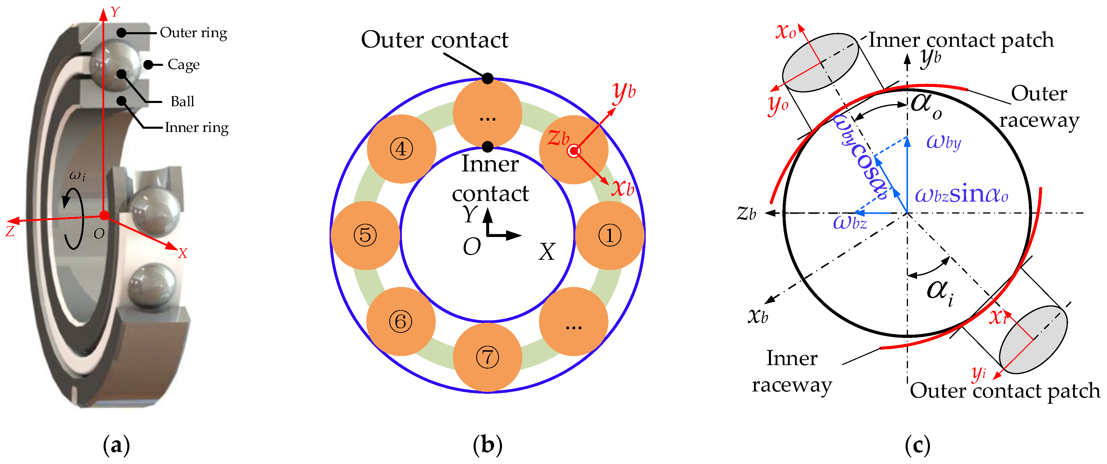
To clearly describe the relative motions between different bearing elements, three types of coordinate systems are established: the inertial coordinate system O-XYZ, the moving coordinate system ob-xbybzb that is attached on the geometry center of the ball as well as local contact coordinate systems between balls and raceways, as shown in Figure 1.
The traction behavior between the ball and raceways significantly influences the dynamic performance of rolling element bearings [36]. As shown in Figure 1c, contact coordinate systems are established between the ball and the inner and outer raceways, where the x coordinate directs the rolling direction of the ball.
The contact between the ball and the raceway is assumed as Hertz contact. In fact, as the thickness of the solid-lubrication coating is within 10 μm, the ratio of the contact radius and the coating thickness is usually larger than three, so the condition for Hertz contact assumption does not hold [37]. However, considering that the distribution of the contact force does not have a significant effect on the overall traction force [10,12,13] and that the micro contact behavior of the particle is not studied in depth in this paper, the Hertz contact assumption is still used to calculate the contact force.
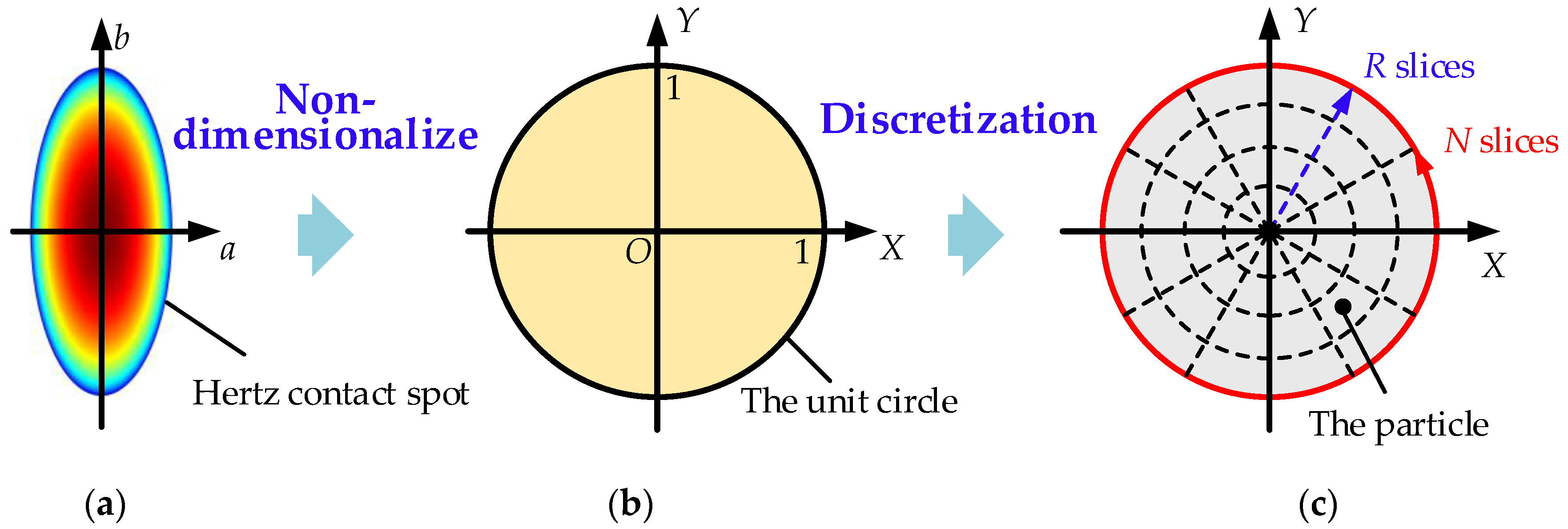
To take the spinning motion and differential sliding behaviors of the ball into consideration, the Hertz elliptical contact patch is first nondimensionalized into a unit circle and then discretized into several arch blocks with each block represented by a particle in its center, as shown in Figure 2. The arch division method ensures that there is no error in meshing the contact surface. Assuming that the dimensionless circle is divided into R parts in the radial direction and N parts in the circumferential direction, respectively, the dimensionless coordinates and area of the (i,j) arch block are respectively represented as follows:
where i is the circumferential number, j is the radial number, and Rj and θi are the radius and polar angle of the (i,j) block, respectively. The dimensionalized coordinates and area of the (i,j) block are obtained using xi,j = aXi,j, yi,j = bYi,j and di,j = abDi,j, where a and b are the elliptical semimajor and semiminor axes, respectively.
Considering the effects of the slide-to-roll and spinning of the ball, the longitudinal and lateral sliding velocities of the (i,j) block are expressed as follows:
where rb is the radius of the ball; δ is the Hertz contact deformation; and ωbx, ωby and ωbz are the rotational speed components of the ball with respect to the xb-axis, yb-axis and zb-axis in the moving coordinate system, respectively. δr, Rc and p are denoted as follows:
where rc = 2rbRi/(rb + Ri), Ri is the radius of the inner race curvature, rp is the pitch radius, and αi and αo are the inner and outer contact angles, respectively.
Kragelskii’s [4] traction model of Ag coating under a contact pressure of 2.5 GPa is developed on the basis of Liu’s [10] experimental data, as shown in Figure 3a. The traction model depicts a relationship between the COF and the relative sliding velocity of a contact particle, as shown in Equation (6):
where A, B, C and D are traction parameters without physical significance, μ is the traction (friction) coefficient, and s is the relative sliding velocity. The stresses px and py of each particle can be obtained by combining Equation (1) with Equation (6) and applying the Amontons–Coulomb friction law. Consequently, the traction force and moment of a contact patch can be calculated by the following integration:
2.2. Modelling of Localized Geometrical-Frictional Defects
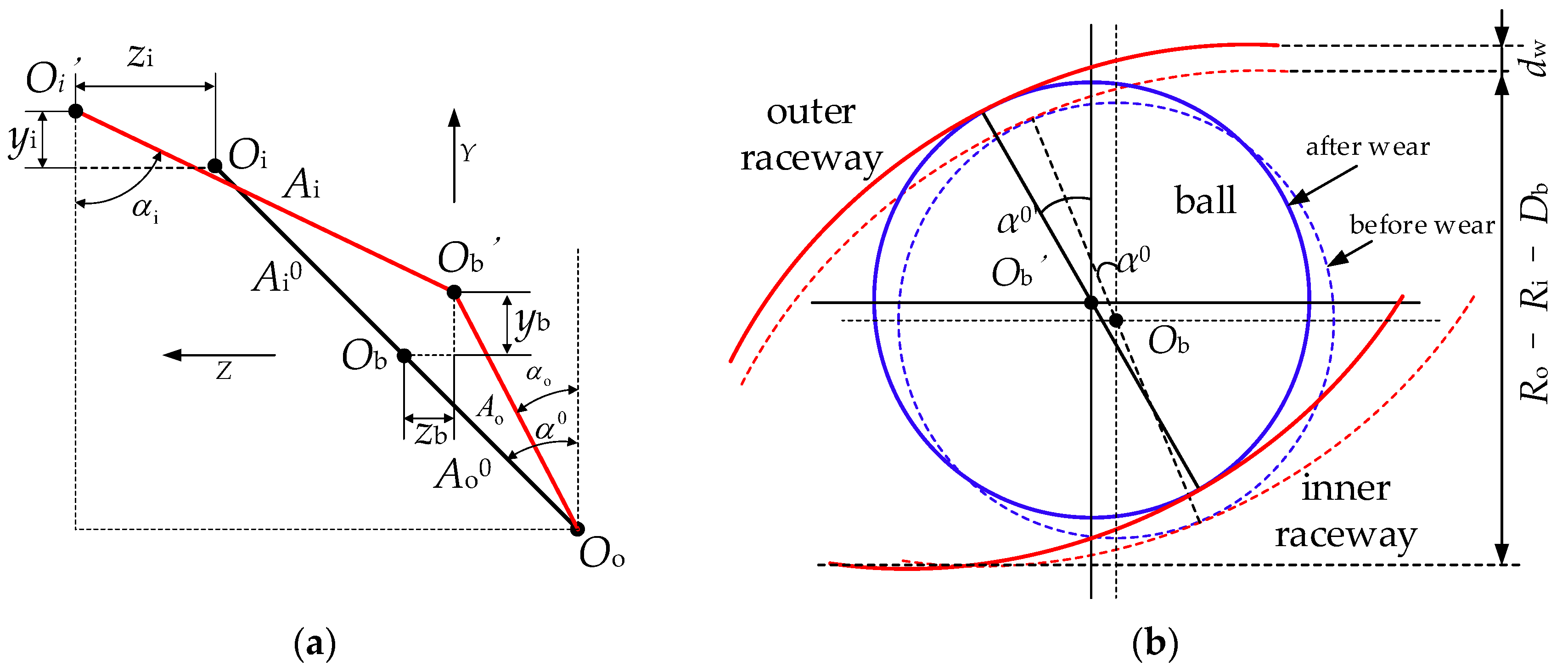
Suppose the outer ring is fixed, the compatibility condition, that is the displacement relationship between the geometric center of the curvature centers of the raceways, is shown in Figure 4a, where the black lines represent the displacement relationship before deformation, while the red lines represent the displacement relationship after deformation. Based on the compatibility condition, the inner and outer contact angles of the ball can be deduced as follows:
where A0 is the initial distance between the curvature centers of the inner and outer raceways, α0 is the initial contact angle, and yi and zi are the displacements of the inner race in the yb and zb directions of the moving coordinate system, respectively.
The spalling in the raceway can be considered as a reduction in the radius of the curvature of the groove, which actually changes the initial contact angle of the balls, and the expression for the initial contact angle of the balls considering the spalling is derived based on the geometrical relationship shown in Figure 4b as follows:
where Ri/o is the inner/outer ring radius, Db is the ball diameter, i/o is the inner/outer curvature radius, and dw is the depth of the local defect fault.
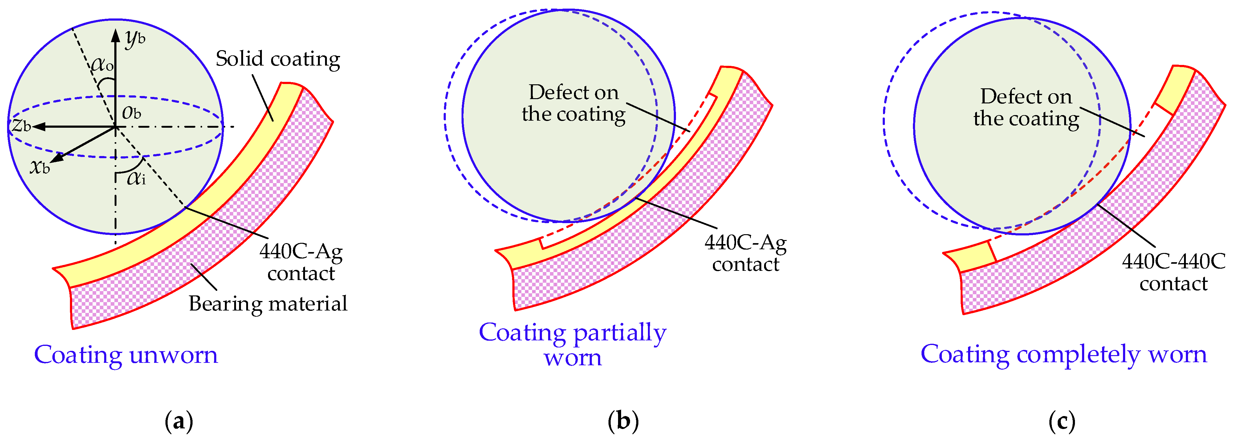
As shown in Figure 5, when the solid-lubricant coating is partially worn, there will be a change in the radius of the raceway curvature, thus changing the initial contact angle of the ball. However, when the coating is completely peeling off, it also leads to a change in the traction coefficient at localized defects in the raceway, which in turn affects the instantaneous traction force and introduces additional shocks to the bearing. Here, when the ball reaches the spalling defect, a 440C-440C contact traction curve from [7] under the rolling velocity of 12 m/s is used to replace the original lubricated traction curve, which is shown in Figure 3b. The traction parameters under Ag-coated and unlubricated conditions are listed in Table 1.
2.3. Dynamic Differential Equations of the Bearing
The ball bearing dynamic model is mainly composed of partial differential equations of each bearing element. Assuming the outer ring is fixed in a housing, in order to simulate the measurement of the vibration of the housing by the sensor, the radial translational DOFs of the X and Y directions are considered for the outer ring, which are subjected to the constraints of stiffness and damping from the housing. The inner ring has three translational DOFs and is subjected to a certain rotational speed and axial and radial loads as well as damping constraints. The six-DOF ball is subjected to contact forces, traction forces, centrifugal forces, fluid drag forces, churning moments and gyroscopic moments. The cage has only a rotational DOF with each pocket having elastic and damping forces in all cage pockets. The stiffness and damping configuration of the ball bearing as a whole and between the cage and balls are shown in Figure 6.
Differential equations for the six-DOF ball are deduced as follows:
where subscripts i and o represent the inner and outer contact, respectively; Tx and Ty are the longitude and lateral traction forces, respectively; Q is the Hertz contact force between the ball and the raceway; Fd is the fluid drag force of the ball; Fc is the centrifugal force of the ball; Mz is the ball–raceway spinning traction moment; Mg is the ball gyroscopic moment; Mcx/cy/cz is the ball churning moment; and Fdc is the ball–cage collision force. The calculation methods of the fluid drag force and churning moment can be found in [17].
ACBBs are generally subjected to axial, radial and moment loads, which means that the inner ring will have translational and torsional displacements [38,39,40]. However, since the CSLBBs are mainly responsible for carrying the axial and radial loads of the turbopump, it is assumed in this paper that the inner ring of the bearings has only three translational DOFs and no torsional DOF. The three-DOF differential equations for the inner ring are formulated as follows:
where Mi is the mass of the inner ring; Ci is the damping of the inner ring; Fx, Fy and Fz are the applied loads along the X, Y and Z directions, respectively; Fix, Fiy and Fiz are resultant of the forces of the inner ring in the moving coordinate system along the xb, yb and zb directions, respectively, which can be calculated using a transformation matrix [16].
The differential equations of the outer ring with two DOFs are given as follows:
where Mo, Ko and Co are the mass, stiffness and damping of the outer ring, respectively.
Since the cage pocket has a certain clearance, elastic and damping forces are generated only when the ball comes into contact with the cage pocket. Assume that the rotational displacement of a certain ball is θm, the rotational displacement of the cage is θc, the angular difference between the two is ∆θ, and rp is the ball pitch radius, the ball–pocket contact force can be obtained as follows:
where Fcbk is the contact force between the k-th ball and the corresponding cage pocket, Kcb and Ccb are the contact stiffness and damping, respectively, and θcl is the pocket clearance.
The differential equation for cage rotation is expressed as follows:
where Ic is the polar moment of inertia of the cage.
The dynamic model is solved by the fourth-order Runge–Kutta method with the step size of 1 × 10⁻⁶ s, and the initial value of the iteration is given by a tribo-quasi-static model that considers the solid-lubrication traction curve and the six-DOF movement of the ball based on the method given in [16].
3. Model Validation
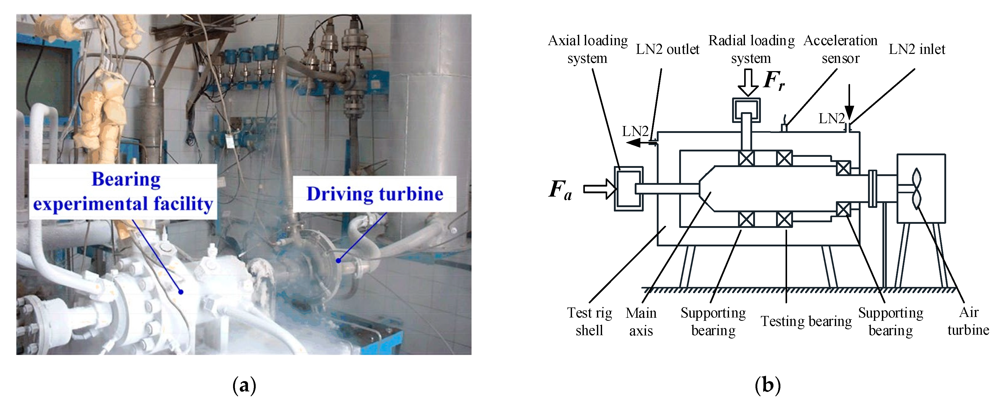
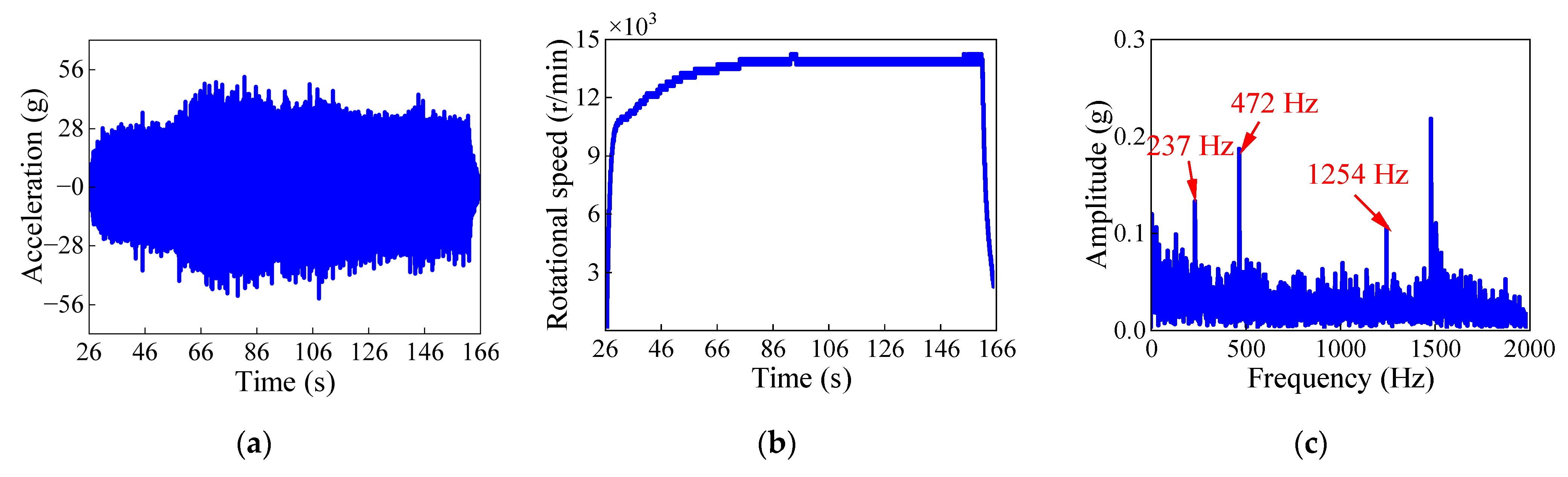
To validate the proposed tribo-dynamic model, the vibration data from a cryogenic ball bearing test rig are analyzed. The structure of the test rig is shown in Figure 7 in which the tested bearing-rotor system is driven from static to a high rotational speed by the air turbine and the bearing is submerged in LN2 fluids. The geometry parameters of the tested bearing can be found in [17]. The analysis of the tested data is given in Figure 8.
As shown in Figure 8a, there is a significant variation in the acceleration signal. Based on the inner-ring rotational data shown in Figure 8b, the bearing first experienced an acceleration process from 0 s to 90 s and then kept a stable speed of 14,000 rpm. It can be found that the vibration amplitude boomed at the beginning as the rotational speed sharply increased from zero to 10,000 r/min. From 30 s to 56 s, the vibration amplitude stayed relatively stable as the rotational speed slowly increased. However, the vibration signal experienced significant fluctuations due to the adjustment of the loading conditions of the test rig from 56 s to 90 s. Subsequently, the rotational speed and operating conditions kept constant, and the amplitude of the vibration signal remained relatively stable.
To obtain the frequency components of the tested bearing, an FFT analysis is performed on the stable signal from 120 s to 150 s. It can be observed in Figure 8c that there are two frequency components in the signal: 237 Hz and 1254 Hz and their octaves. While the 237 Hz component is the inner-ring rotational frequency, the 1254 Hz component corresponds to the outer-ring defect frequency. Therefore, the cage rotational frequency can be calculated as 1254/13 = 96.45 Hz, and the average cage rotational speed is 5787 r/min.
Based on the experimental loads (Fr = 20,000 N, Fa = 40,000 N), the dynamic and static responses at a rotational speed of 14,000 r/min are calculated using the classical Jones–Harris (J–H) quasi-static model [14,15], the tribo-quasi-static model and the tribo-dynamics model proposed in this paper. The average values of some selected parameters of all the balls are compared in Table 2.
According to Table 2, it can be found that the errors of the cage rotational speed of the theoretical models are 1.88%, 0.97% and 0.81%, respectively, compared with the experiment. Since the J–H model does not consider the effect of fluid, the calculated ball rotational speed is higher than that of the other two models. In addition, the limitations of the degrees of freedom and the lack of friction prevent the J–H model from accurately calculating the contact, attitude and yaw angles of the balls. In particular, as the gyroscopic moments of the balls are assumed to be completely offset by friction force, the J–H model is unable to compute the correct yaw angle and the ball rotation component ωbx.
4. Dynamic Behavior of the Bearing under Healthy Condition
Based on the working conditions listed in Section 3, the dynamic response of the bearing under healthy conditions is studied in this section. It can be observed from Figure 9a,b that the vibration amplitude is approximately 2.7 m/s2 and that the inner-ring’s trajectory is smooth, which means that there is no obvious impact in the raceways of the bearing. However, the cage rotational speed is not stable. It can be observed in Figure 9c that the time interval of each fluctuating period is approximately 7.92 × 10⁻⁴ s, which corresponds to a frequency of 1263 Hz, which is the passing frequency of all the balls. Figure 9d shows the ball–cage pocket collision force of the No. 13 ball from which it can be observed that the ball hits the cage pocket in a time interval of 0.01025 s, which corresponds to a frequency of 97.56 Hz, which indicates the cage rotating frequency.
To further study the ball–cage interaction mechanism, polar plots of the ball’s behavior in an entire orbital rotation of the ball are given in Figure 10. From Figure 10a, it can be found that the ball–cage collision behavior mainly occurs at the range of 210~300° of the ball’s azimuth position. Since the inner ring is subjected to a radial load of 20,000 N, which points towards the positive x position, the azimuth range of −90~90° is considered as a heavily loaded zone, and the 90~270° is a slightly loaded zone. As shown in Figure 10b, the ball–inner contact force increases gradually from 180° to 360°, which means that the ball–cage collision phenomenon occurs during the process of the ball entering the heavy-loaded zone from the lightly loaded zone. It can be observed that the ball has a higher orbital speed at the slightly loaded zone and a lower orbital speed at the heavily loaded zone, between which there is a fluctuation in the range of 210~300°.
Due to the need for thrust provided by the ball to overcome the fluid churning moment, the ball will collide with the cage pocket when the ball’s orbital velocity reaches a certain level. However, the collision force of the cage is not the only reason for the decrease in the ball’s orbital speed in the heavily loaded zone. From Figure 10c, it can be observed that, even if the ball no longer contacts the cage pocket, its orbital speed continues to decrease.
The above analysis indicates that, when the ball moves from the slightly loaded zone to the heavily loaded zone, it collides with the cage pocket as its orbital speed is larger than that of the pocket. However, as the ball–raceway contact forces increase, the ball’s orbital speed will decrease gradually; thus, the orbital speed of the ball becomes no longer larger than that of the cage pocket and finally terminates the collision.
5. Numerical Study of the Fault Mechanism
In this section, the outer raceway geometrical-frictional, solid-lubrication defects are implanted into the proposed CSLBB tribo-dynamic model. To study the tribo-dynamic mechanism of the CSLBB, different types of dynamic response, including dynamic acceleration signals, cage transient rotational speeds, frequency spectrums, the traction forces, etc., under a series of quantified defects are compared.
5.1. Effect of the Local Defect Depth
Figure 11 shows the time-domain and frequency-domain response of the CSLBB with a local defect on the outer race coating. The width of the defect is L = 5 mm, and the depth of the defect is D = 2 μm, while the total thickness of the Ag lubrication coating is 10 μm. As shown in Figure 11a, the acceleration amplitude of the outer ring is 21 m/s2, which is almost seven times that under healthy conditions. As the signal fluctuates regularly, two repeated cycles are plotted in Figure 11b. It can be observed in Figure 11b that the period of each cycle is 0.0103 s, which is equal to the rotational period of the cage. In addition, it can be observed from Figure 11b that there are 13 pulses in each cage period with each pulse having a time interval of 7.92 × 10⁻⁴ s, which corresponds to the outer-ring fault frequency of 1263 Hz. To further study the fault pulse, a detailed plot of the pulse is given in Figure 11c, where it can be observed that the fault pulse is actually a double-pulse with a time interval of 8 × 10⁻⁵ s, which is equal to the time for the ball to pass through the defect. As demonstrated in Section 2.3, a defect in the raceway will lead to a sudden change in the contact angle of the ball; thus, the defect will bring an impact to the bearing when the ball moves into and out of the defect zone. Therefore, the time interval of the double-pulse can be a potential way to indicate the defect width.
As illustrated in Figure 11b, the amplitude of the fault double-pulse varies with the period of cage rotation, which means that the fault pulse signal may be amplitude modulated by the cage frequency. Therefore, to reveal the frequency characteristics of the fault, the vibration signal is processed by the fast Fourier transform (FFT) after a Hilbert demodulation, as shown in Figure 11d. As displayed in the envelope spectrum, there are only two types of frequency components in the signal: the cage frequency of 95 Hz and the outer race fault frequency of 1265 Hz, which is the product of the ball pass frequency and the number of balls [41,42] and their octaves. Among the two frequency components, the cage frequency has the largest amplitude; so, it is the most obvious wave in Figure 11a. In addition, the fault frequency is accompanied by a 95 Hz sideband, which is a typical characteristic of the amplitude modulation phenomenon, which validates the above inference.
To study the effect of defect depth on the fault behavior of CSLBBs, the dynamic response under a defect depth of 0 (healthy), 2 μm, 4 μm, 6 μm, 8 μm and 10 μm is obtained based on the proposed tribo-dynamic model. Figure 12 shows the peak values of the fault double-pulse with different defect depths, based on which, the influence of the defect depth can be divided into three phases. The first phase is the coating wear phase; it can be observed that, when the defect depth is smaller than 10 μm, the peak value increases linearly with the increase in defect depth with an average gradient of 9 m/s2 per micrometer. The second phase is the coating peeling phase, where the peak value grows sharply once the defect depth reaches 10 μm. It is illustrated in Figure 12 that the gradient between 8 μm and 10 μm is as high as 36 m/s2 per micrometer, which is four times larger than when the defect depth is below 10 μm. The third phase is the bearing wear phase in which the defect is caused by the peeling of the bearing material. It can be observed in the third phase that the gradient of the curve returns to 9 m/s2 per micrometer.
In summary, the peak value of the double-pulse changes almost linearly with the increase in the defect depth, and the sudden rise of the gradient can be an indicator of the lubrication condition. However, as the peeling process of the local coating may be very fast, the capture of time-domain vibration signals must be sufficiently accurate.
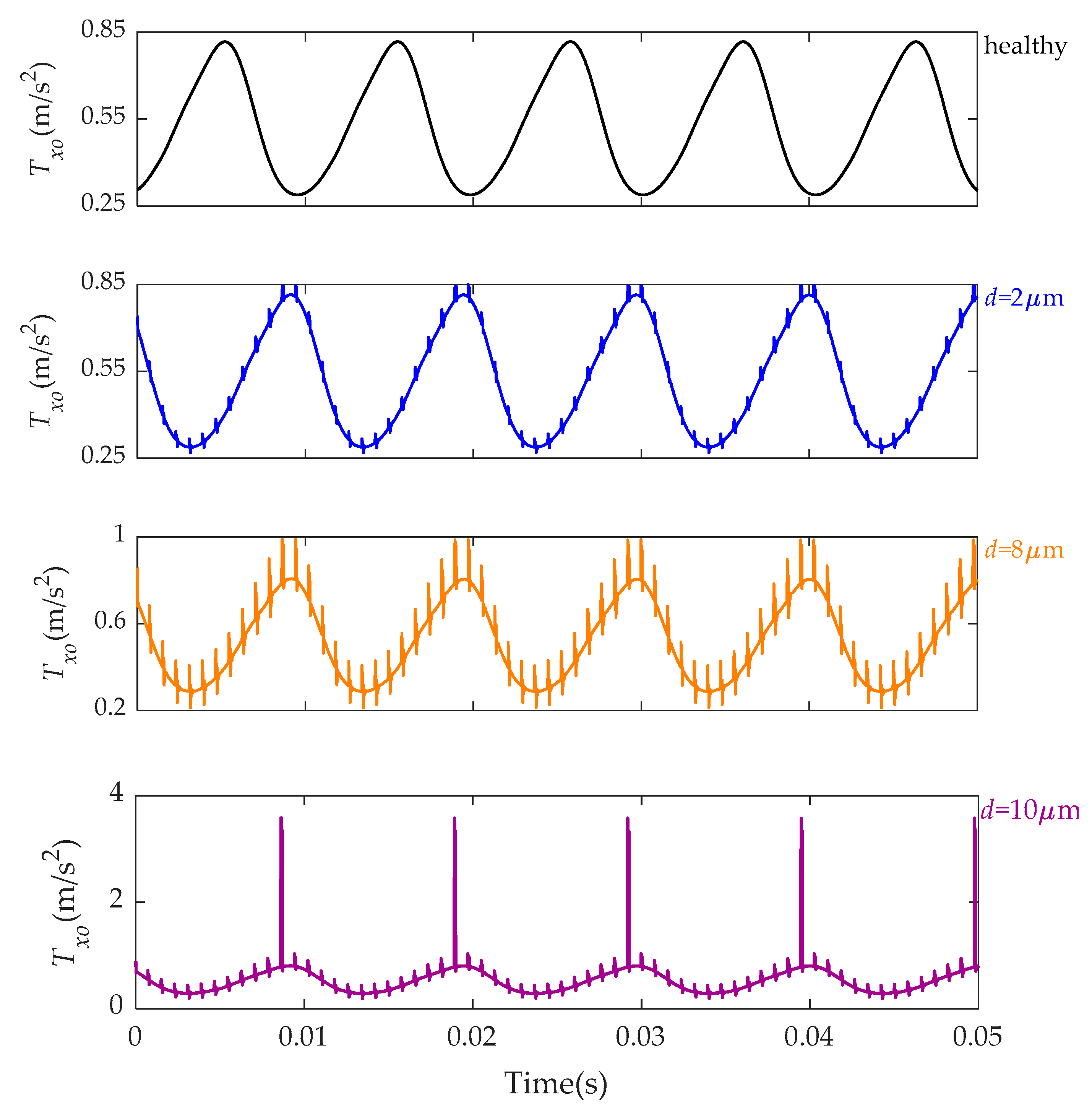
From the comparison of the outer traction force under healthy and defective conditions with a depth of 2 μm, 8 μm and 10 μm in Figure 13, it can be observed that the defect will cause an impact in the traction force. As the impact amplitude increases with the increasing defect depth, the traction force soars to be almost five times larger than the original value at the moment that the ball enters the geometry-frictional defect. When the defect depth is within 10 μm, the fault excitation is a pure geometry one; thus, it influences the ball–raceway contact force, as shown in Figure 14b. However, from Figure 14b, it can also be observed that the frictional excitation counterpart has no obvious effect on the ball–cage collision force, ball–raceway contact force and ball orbital speed.
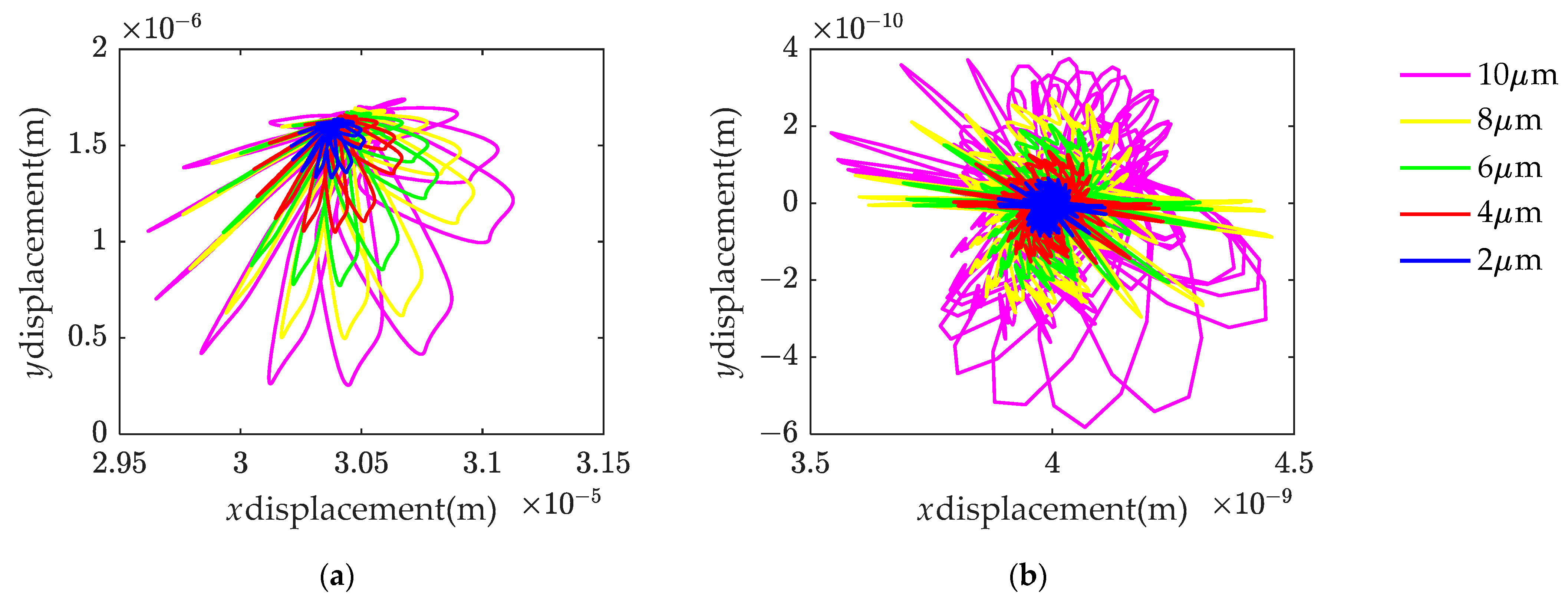
Therefore, it can be concluded that, when the solid-lubricating film peels off, the severe vibration of the bearing is not caused by the interaction between the ball and the cage or raceways but by the increased traction force directly acting on the raceway; the inner- and outer-ring trajectories shown in Figure 15 are proof.
5.2. Effect of the Local Defect Widths
To explore the influencing mechanism of defect width on the tribo-dynamic performance of CSLBBs, the responses of the bearing under a defect depth of 10 μm and widths of 5 mm, 10 mm, 15 mm, 20 mm and 25 mm are calculated.
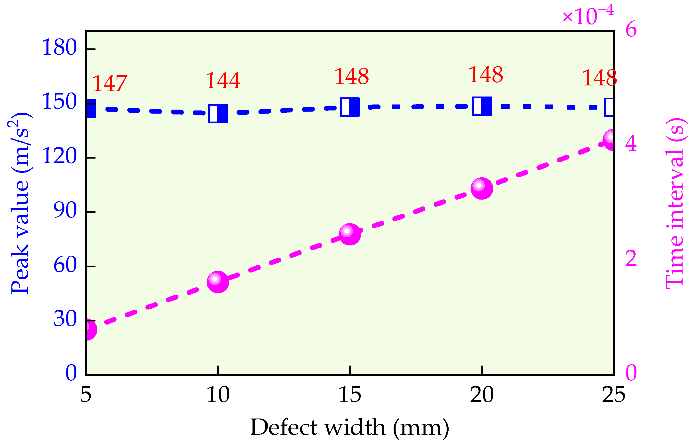
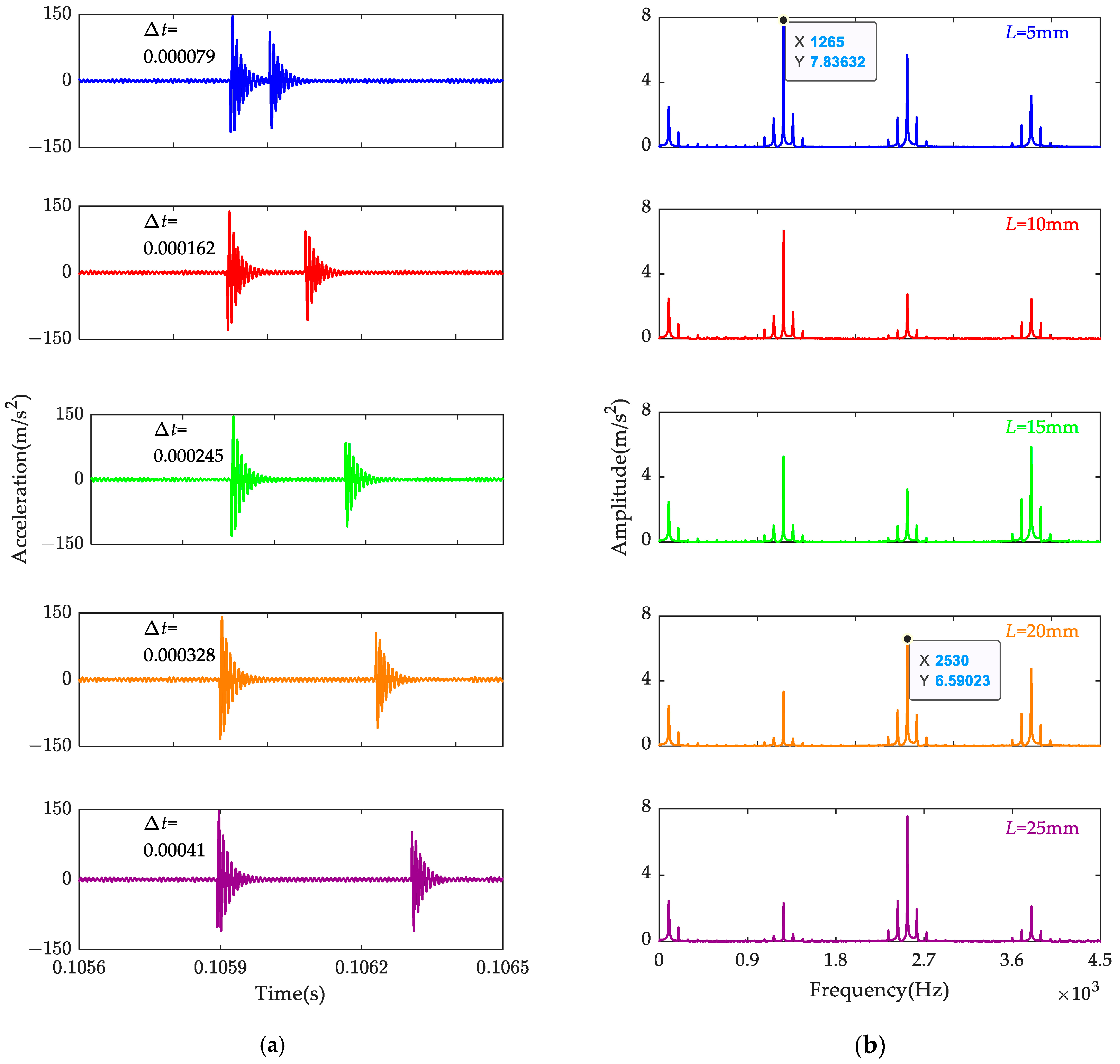
The blue curve in Figure 16 shows the peak value of the defect double-pulse under different defect widths, which indicates that the defect width has little effect on the vibration amplitude of the bearing. Instead, the time interval of each double-pulse increases linearly with the increase in the defect width, as shown in the pink curve in Figure 16. It can be observed in Figure 17 that the time intervals for 5 mm, 10 mm, 15 mm, 20 mm and 25 mm are 7.9 × 10⁻⁵ s, 1.62 × 10⁻⁴ s, 2.45 × 10⁻⁴ s, 3.25 × 10⁻⁴ s and 4.10 × 10⁻⁴ s, respectively. In addition, as the defect width changes the time interval, there is still a change in the frequency spectrum. As illustrated in Figure 17b, the one-time octave of the outer-ring fault frequency of 1265 Hz is the most significant component when the defect width is between 5 mm and 15 mm. However, the two-time octave becomes the most significant one when the defect width is larger than 20 mm. Therefore, while the time interval of the double-pulse can be used to identify a certain defect width, the frequency spectrum can be applied to assess the rough range of it.
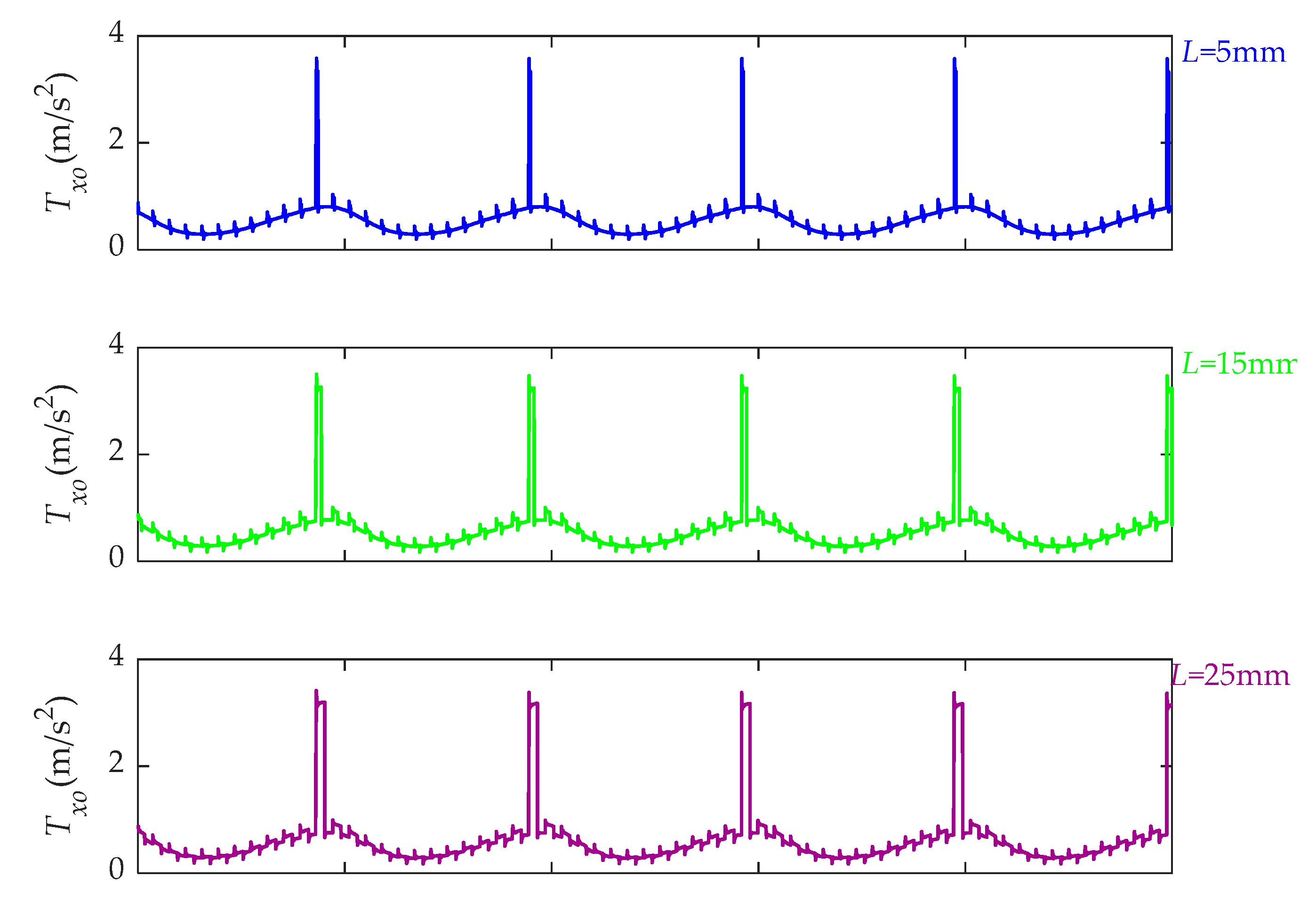
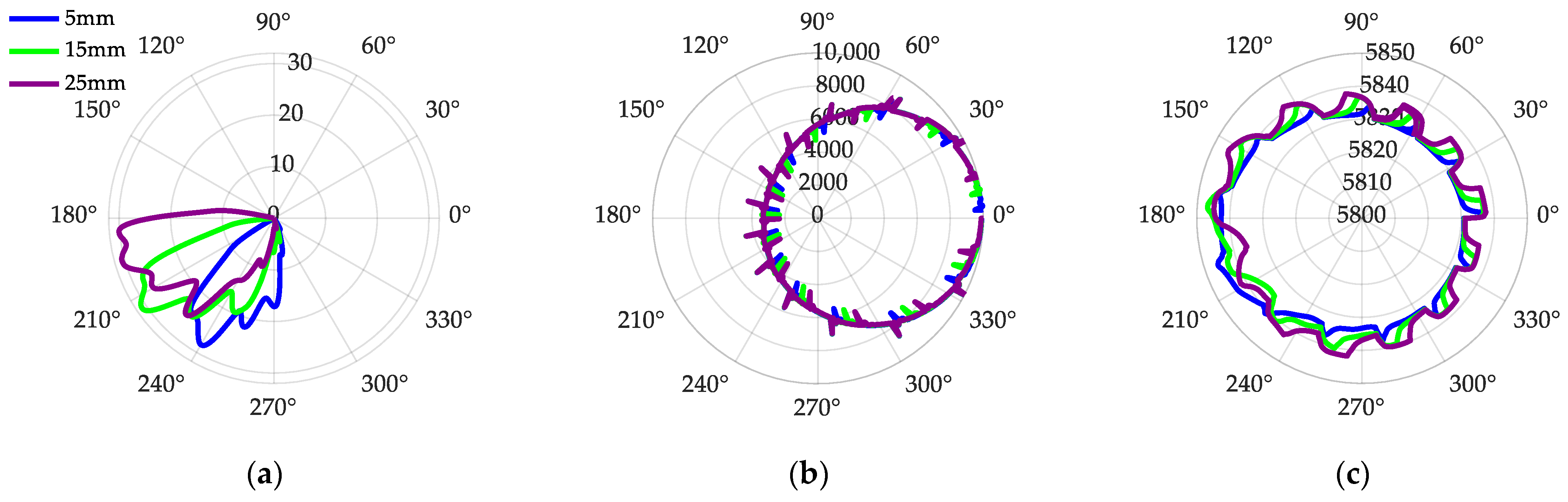
To reveal the influencing mechanism of the defect width, traction force and ball–cage/race interaction are illustrated in Figure 18 and Figure 19. The outer longitude traction force under a defect width of 5 mm, 15 mm and 25 mm is displaced in Figure 18. While the defect width has little effect on the impact amplitude of the traction force, the increasing defect width increases the duration of the impact. As shown in Figure 19, the defect width has an obvious influence on the phase of the ball–cage collision force, ball–raceway contact force and the ball orbital speed. As the defects studied in this section are all geometry-frictional excitations, the increased width of the defect increases the ball’s orbital speed, leading the ball to collide with the cage in advance. As shown in Figure 19b, although there is just one defect on the outer raceway, the contact force of the ball fluctuates several times in a whole orbital rotation. As already analyzed in Section 5.2, this is because the fault excitation significantly changes the dynamic response of the race; therefore, whenever a ball passes through the fault area, it will significantly affect the behavior of the race, thereby affecting all other balls.
6. Conclusions
Aiming to reveal the dynamic mechanism of the cryogenic solid-lubricated ball bearing in turbopumps of liquid rocket engines, a tribo-dynamic model is developed in this paper. The model considers the solid-lubricated traction, six-DOF motion of the ball and the local geometrical-frictional excitations of the solid-lubrication coating. To explore the fault mechanism, tribo-dynamic responses are studied under healthy and defective conditions. The following conclusions are drawn from this study:
(1) The low-temperature fluid environment of turbopump ball bearings plays an important role in maintaining the stability of the cage. Due to the effect of fluid churning resistance, the cage requires the thrust of the ball to keep its rotation, which is located in the area where the ball transitions from the slightly loaded zone to the heavily loaded zone.
(2) The change in the amplitude of the bearing vibration acceleration and its derivative can be used as a reference to determine the depth of defects of the cryogenic solid-lubricated ball bearing. In general, the vibration amplitude has a linear variation relationship with the defect depth. However, when the solid-lubrication coating is locally peeling off, the vibration of the bearing increases dramatically. Therefore, monitoring the rate of increase in vibration acceleration amplitude is critical for determining the lubrication status during the gradual wear of the solid lubrication of the bearing.
(3) The geometrical-frictional failure excitation of solid-lubrication coatings significantly increases bearing vibration by directly affecting the traction force between the balls and the raceways. Therefore, whenever a ball passes through the fault area, it will significantly affect the behavior of the race, thereby affecting all other balls.
(4) The width of the defect can be diagnosed by monitoring the double-pulse time interval and spectrum of the bearing vibration signal. An increase in the width of the defect lengthens the time interval between the entry and exit of the balls from the defective impact. When the defect width is lower than 15 mm, the 1× octave of the outer-ring fault frequency in the frequency spectrum is more obvious, while when the fault width exceeds 20 mm, the 2× octave is more obvious.
Author Contributions
Y.Z. (Yuhao Zhao): Methodology, Software, Validation, Investigation, Formal analysis, Writing—original draft. Z.C.: Project administration, Data curation, Resources. Y.Z. (Yanyang Zi): Conceptualization, Resources, Supervision, Project administration. M.Z.: Data curation, Resources. T.T.: Methodology, Validation, Software. All authors have read and agreed to the published version of the manuscript.
Funding
This research was funded by the National Key Research and Development Program of China (2023YFB4604700), the National Natural Science Foundation of China (No. 52175119) and the 2023 Key Laboratory Stabilization Foundation of China (No. HTKJ2023KL011004).
Data Availability Statement
All data generated during this study are included in this article, and the datasets are available from the corresponding author on reasonable request.
Acknowledgments
The authors are grateful for the support of Xi’an Aerospace Propulsion Institution (China Aerospace Science and Technology Corporation).
Conflicts of Interest
The authors declare no conflicts of interest.
Nomenclature
| Symbols | Meaning | Symbols | Meaning |
| a | Elliptical semi-major axis | Mo | Outer-ring mass |
| ACBB | Angular contact ball bearing | N | Number of circumference divisions |
| A, B, C, D | Traction curve parameters | O-XYZ | Inertial coordinate system |
| b | Elliptical semi-minor axis | ob-xbybzb | Moving coordinate system |
| CSLBB | Cryogenic solid-lubricated ball bearing | px/y | Longitude and lateral traction stresses |
| Cb | Ball damping | Qi/o | Inner/outer contact force |
| Ccb | Ball–cage contact damping | rp | Ball pitch radius |
| Ci | Inner-ring damping | R | Number of radial divisions |
| Co | Outer-ring damping | Rj | Radius of the (i,j) block |
| Db | Ball diameter | rp | Ball pitch radius |
| dw | Wear fault depth | Ri/o | Inner/outer ring radii |
| DOF | Degree-of-freedom | Tx/y | Longitude/lateral traction force |
| Di,j | Area of the (i,j) arch block | xb, yb, zb | Displacement of the ball |
| Fc | Ball centrifugal force | xi, yi, zi | Displacement of the inner ring |
| Fcbk | Ball–cage pocket contact force | (Xi,j,Yi,j) | Dimensionless coordinates |
| Fd | Ball fluid drag force | α0 | Initial contact angle |
| Fdc | Ball–cage collision force | αi/o | Inner/outer contact angle |
| Fix/iy/iz | Resultant of forces of the inner ring | δ | Hertz contact deformation |
| Fx/y/z | Inner-ring applied load | δr, Rc, p, rc | Differential contact parameters |
| Ib | Polar moment of inertia of the ball | ∆θ | Ball–cage angular difference |
| Ic | Polar moment of inertia of the cage | ∆vx/y | Sliding velocities of the (i,j) block |
| Kcb | Ball–cage contact stiffness | θi | Polar angle of the (i,j) block |
| Ko | Outer-ring stiffness | θbx, θby, θbz | Polar angle of the ball |
| M | Traction moment | θc | Cage rotational displacement |
| Mb | Ball mass | θcl | Cage pocket clearance |
| Mch | Cage churning moment | θm | Cage angular position |
| Mcx/cy/cz | Ball churning moment | θm/c | Ball/cage pocket azimuth position |
| Mgx/gy/gz | Ball gyroscopic moment | ωbx/y/z | Rotational speed components of the ball |
| Mi | Inner-ring mass | i/o | Inner/outer curvature radii |
References
- Nosaka, M.; Oike, M.; Kikuchi, M.; Mayumi, T. Tribo-Characteristics of Cryogenic Hybrid Ceramic Ball Bearings for Rocket Turbopumps: Self-Lubricating Performance. Tribol. Trans. 1997, 40, 21–30. [Google Scholar] [CrossRef]
- Xu, J.; Li, C.; Miao, X.; Zhang, C.; Yuan, X. An Overview of Bearing Candidates for the Next Generation of Reusable Liquid Rocket Turbopumps. Chin. J. Mech. Eng. 2020, 33, 26. [Google Scholar] [CrossRef]
- Miao, X.; Hu, M.; Li, A.; Wang, D.; Weng, L.; Li, X.; Zhang, G. Investigation on the Lubricity of Self-Lubricating Ball Bearings for Cryogenic Turbine Pump. Tribol. Int. 2018, 121, 45–53. [Google Scholar] [CrossRef]
- Kragelskii, I.V. Friction and Wear; Butterwonhs: London, UK, 1965. [Google Scholar]
- Gupta, P.K. Traction Coefficients for Some Solid Lubricants for Rolling Bearing Dynamics Modeling. Tribol. Trans. 2000, 43, 647–652. [Google Scholar] [CrossRef]
- Tevaarwerk, J.L. Rolling, Slip and Traction Measurements on Low Modulus Materials; Contractor Report (CR) No. NASA-CR-174909; NASA: Washington, DC, USA, 1985. [Google Scholar]
- Chang, L.; Hall, P.; Thom, R. Scuffing Characteristics of High-Load Rolling/Sliding Contacts Operating in Liquid Oxygen—Effects of Materials and Surface Roughness. Tribol. Trans. 1998, 41, 87–95. [Google Scholar] [CrossRef]
- Gupta, P.K.; Gibson, H.G. Real-Time Dynamics Modeling of Cryogenic Ball Bearings with Thermal Coupling. J. Tribol. 2021, 143, 031201. [Google Scholar] [CrossRef]
- Kwak, W.; Lee, J.; Lee, Y.B. Theoretical and Experimental Approach to Ball Bearing Frictional Characteristics Compared with Cryogenic Friction Model and Dry Friction Model. Mech. Syst. Signal Process. 2019, 124, 424–438. [Google Scholar] [CrossRef]
- Liu, F.; Su, B.; Zhang, G.; Ren, J.; Zhang, W. Development of a Cryogenic Tester with Air Bearing to Test Sliding-Rolling Contact Friction. Lubricants 2022, 10, 119. [Google Scholar] [CrossRef]
- Su, B.; Mao, S.; Zhang, G.; Li, H.; Cui, Y. Dynamics-Based Calculation of the Friction Power Consumption of a Solid Lubricated Bearing in an Ultra-Low Temperature Environment. Lubricants 2023, 11, 372. [Google Scholar] [CrossRef]
- Chen, W.; Ma, Z.; Gao, L.; Li, X.; Pan, J. Quasi-Static Analysis of Thrust-Loaded Angular Contact Ball Bearings Part I: Theoretical Formulation. Chin. J. Mech. Eng. 2012, 25, 71–80. [Google Scholar] [CrossRef]
- Chen, W.; Ma, Z.; Gao, L.; Li, X.; Pan, J. Quasi-Static Analysis of Thrust-Loaded Angular Contact Ball Bearings Part II: Results and Discussion. Chin. J. Mech. Eng. 2012, 25, 81–87. [Google Scholar] [CrossRef]
- Harris, T.A.; Kotzalas, M.N. Rolling Bearing Analysis: Essential Concepts of Bearing Technology; CRC Press: Boca Raton, FL, USA, 2007. [Google Scholar]
- Harris, T.A.; Kotzalas, M.N. Rolling Bearing Analysis: Advanced Concepts of Bearing Technology; CRC Press: Boca Raton, FL, USA, 2007. [Google Scholar]
- Zhao, Y.; Ma, Z.; Zi, Y. Skidding and Spinning Investigation for Dry-Lubricated Angular Contact Ball Bearing under Combined Loads. Friction 2023, 11, 1987–2007. [Google Scholar] [CrossRef]
- Zhao, Y.; Zi, Y.; Chen, Z.; Zhang, M.; Zhu, Y.; Yin, J. Power Loss Investigation of Ball Bearings Considering Rolling-Sliding Contacts. Int. J. Mech. Sci. 2023, 250, 108318. [Google Scholar] [CrossRef]
- Haslam, A.H.; Schwingshackl, C.W.; Rix, A.I.J. A Parametric Study of an Unbalanced Jeffcott Rotor Supported by a Rolling-Element Bearing. Nonlinear Dyn. 2020, 99, 2571–2604. [Google Scholar] [CrossRef]
- Shi, Z.; Liu, J. An Improved Planar Dynamic Model for Vibration Analysis of a Cylindrical Roller Bearing. Mech. Mach. Theory 2020, 153, 103994. [Google Scholar] [CrossRef]
- Wang, Z.; Li, G.; Zhou, X.; Zhang, H.; Lin, Z.; Jia, S. Dynamic Analysis of Deep Groove Ball Bearing with Localized Defects and Misalignment. J. Sound Vib. 2024, 568, 118071. [Google Scholar] [CrossRef]
- Tu, W.; Luo, Y.; Yu, W. Dynamic Interactions between the Rolling Element and the Cage in Rolling Bearing under Rotational Speed Fluctuation Conditions. J. Tribol. 2019, 141, 091101. [Google Scholar] [CrossRef]
- Tu, W.; Luo, Y.; Yu, W.; Yu, Y. Investigation of the Dynamic Local Skidding Behaviour of Rollers in Cylindrical Roller Bearings. Proc. Inst. Mech. Eng. Part K J. Multi-Body Dyn. 2019, 233, 899–909. [Google Scholar] [CrossRef]
- Liu, Y.; Chen, Z.; Tang, L.; Zhai, W. Skidding Dynamic Performance of Rolling Bearing with Cage Flexibility under Accelerating Conditions. Mech. Syst. Signal Process. 2021, 150, 107257. [Google Scholar] [CrossRef]
- Meng, F.; Gong, J.; Yang, S.; Huang, L.; Zhao, H.; Tang, X. Study on Tribo-Dynamic Behaviors of Rolling Bearing-Rotor System Based on Neural Network. Tribol. Int. 2021, 156, 106829. [Google Scholar] [CrossRef]
- Liu, Y.; Wang, W.; Qing, T.; Zhang, Y.; Liang, H.; Zhang, S. The Effect of Lubricant Temperature on Dynamic Behavior in Angular Contact Ball Bearings. Mech. Mach. Theory 2020, 149, 103832. [Google Scholar] [CrossRef]
- Liu, Y.; Liu, H. A Coupled Model of Angular-Contact Ball Bearing–Elastic Rotor System and Its Dynamic Characteristics under Asymmetric Support. J. Vib. Eng. Technol. 2021, 9, 1175–1192. [Google Scholar] [CrossRef]
- Ma, S.; He, G.; Yan, K.; Li, W.; Zhu, Y.; Hong, J. Structural Optimization of Ball Bearings with Three-Point Contact at High-Speed. Int. J. Mech. Sci. 2022, 229, 107494. [Google Scholar] [CrossRef]
- Wen, C.; Meng, X.; Gu, J.; Xiao, L.; Jiang, S.; Bi, H. Starved Lubrication Analysis of Angular Contact Ball Bearing Based on a Multi-Degree-of-Freedom Tribo-Dynamic Model. Friction 2023, 11, 1395–1418. [Google Scholar] [CrossRef]
- Patel, V.N.; Tandon, N.; Pandey, R.K. A Dynamic Model for Vibration Studies of Deep Groove Ball Bearings Considering Single and Multiple Defects in Races. J. Tribol. 2010, 132, 041101. [Google Scholar] [CrossRef]
- Niu, L.; Cao, H.; Xiong, X. Dynamic Modeling and Vibration Response Simulations of Angular Contact Ball Bearings with Ball Defects Considering the Three-Dimensional Motion of Balls. Tribol. Int. 2017, 109, 26–39. [Google Scholar] [CrossRef]
- Gupta, P.K. Advanced Dynamics of Rolling Elements; Springer Science & Business Media: New York, NY, USA, 2012. [Google Scholar]
- Jiang, Y.; Huang, W.; Luo, J.; Wang, W. An Improved Dynamic Model of Defective Bearings Considering the Three-Dimensional Geometric Relationship between the Rolling Element and Defect Area. Mech. Syst. Signal Process. 2019, 129, 694–716. [Google Scholar] [CrossRef]
- Liu, J.; Xu, Y.; Pan, G. A Combined Acoustic and Dynamic Model of a Defective Ball Bearing. J. Sound Vib. 2021, 501, 116029. [Google Scholar] [CrossRef]
- Deng, S.; Zhu, X.; Qian, D.; Jiang, S.; Hua, L. Nonlinear Dynamic Mechanisms of Angular Contact Ball Bearings with Waviness and Cage Whirl Motion. Nonlinear Dyn. 2022, 109, 2547–2571. [Google Scholar] [CrossRef]
- Zhao, Y.; Zi, Y.; Chen, Z.; Zhang, M. Effects of Early Wear on Dynamic Characteristics of Cryogenic Ball Bearings. In Proceedings of the Lubrication, Maintenance and Tribotechnology (LUBMAT 2023), Preston, UK, 17–19 July 2023. [Google Scholar]
- Gupta, P.K. Some Dynamic Effects in High-Speed Solid-Lubricated Ball Bearings. ASLE Trans. 1983, 26, 393–400. [Google Scholar] [CrossRef]
- Naghieh, G.R.; Rahnejat, H.; Jin, Z.M. Characteristics of Frictionless Contact of Bonded Elastic and Viscoelastic Layered Solids. Wear 1999, 232, 243–249. [Google Scholar] [CrossRef]
- Aini, R.; Rahnejat, H.; Gohar, R. A Five Degrees of Freedom Analysis of Vibrations in Precision Spindles. Int. J. Mach. Tools Manuf. 1990, 30, 1–18. [Google Scholar] [CrossRef]
- Xu, H.Y.; Wang, P.F.; Ma, H.; Yang, Y.; Li, X.P.; Luo, Z.; Han, Q.; Wen, B. Dynamic Behaviors and Contact Characteristics of Ball Bearings in a Multi-Supported Rotor System under the Effects of 3d Clearance Fit. Mech. Syst. Signal Process. 2023, 196, 110334. [Google Scholar] [CrossRef]
- Wang, P.F.; Yang, Y.; Xu, H.Y.; Ma, H.; Han, Q.K.; Luo, Z.; Wen, B.C. Effect of Static and Dynamic Misalignment of Rolling Bearing on Nonlinear Vibration Characteristics of Rotor System. J. Cent. South Univ. 2023, 30, 871–903. [Google Scholar] [CrossRef]
- Wardle, F.P. Vibration Forces Produced by Waviness of the Rolling Surfaces of Thrust Loaded Ball Bearings Part 1: Theory. Proc. Inst. Mech. Eng. Part C J. Mech. Eng. Sci. 1988, 202, 305–312. [Google Scholar] [CrossRef]
- Lynagh, N.; Rahnejat, H.; Ebrahimi, M.; Aini, R. Bearing Induced Vibration in Precision High Speed Routing Spindles. Int. J. Mach. Tools Manuf. 2000, 40, 561–577. [Google Scholar] [CrossRef]
Figure 1.
Coordinate system setup: (a) bearing inertia coordinate system; (b) moving coordinate system attached on the geometry center of the balls; (c) local contact coordinate systems.
Figure 1.
Coordinate system setup: (a) bearing inertia coordinate system; (b) moving coordinate system attached on the geometry center of the balls; (c) local contact coordinate systems.

Figure 2.
Discretization method of the contact patch: (a) the Hertz contact patch; (b) the unit circle; (c) discretization method of the unit circle.
Figure 2.
Discretization method of the contact patch: (a) the Hertz contact patch; (b) the unit circle; (c) discretization method of the unit circle.

Figure 3.
Traction curves under lubricated and unlubricated conditions: (a) traction curve of Ag solid-lubrication coating [10]; (b) traction curve under 440C-440C unlubricated condition [7].

Figure 4.
Typical compatibility condition and the effect of raceway defect on initial contact angle: (a) compatibility condition; (b) initial contact angle variation considering raceway defect failure.
Figure 4.
Typical compatibility condition and the effect of raceway defect on initial contact angle: (a) compatibility condition; (b) initial contact angle variation considering raceway defect failure.

Figure 5.
The geometrical-frictional coating defect: (a) healthy coating; (b) the coating is partially removed; (b) the coating is completely worn out.
Figure 5.
The geometrical-frictional coating defect: (a) healthy coating; (b) the coating is partially removed; (b) the coating is completely worn out.

Figure 6.
The dynamic model: (a) the whole model; (b) the ball–cage pocket interaction.

Figure 7.
The cryogenic ball bearing vibration tester: (a) actual photograph; (b) schematic diagram [2].
Figure 7.
The cryogenic ball bearing vibration tester: (a) actual photograph; (b) schematic diagram [2].

Figure 8.
Experimental data of the tested cryogenic ball bearing: (a) the entire vibration acceleration signal; (b) rotational speed of the inner ring; (c) FFT spectrum of the stable signal.
Figure 8.
Experimental data of the tested cryogenic ball bearing: (a) the entire vibration acceleration signal; (b) rotational speed of the inner ring; (c) FFT spectrum of the stable signal.

Figure 9.
Dynamic response of the bearing under healthy conditions: (a) outer-ring vibration acceleration; (b) inner-ring trajectory; (c) cage transient speed; (d) ball–cage collision force.
Figure 9.
Dynamic response of the bearing under healthy conditions: (a) outer-ring vibration acceleration; (b) inner-ring trajectory; (c) cage transient speed; (d) ball–cage collision force.

Figure 10.
Polar plots of ball performance under an entire rotation: (a) ball–cage collision force; (b) ball–inner raceway contact force; (c) ball orbital rotational speed.
Figure 10.
Polar plots of ball performance under an entire rotation: (a) ball–cage collision force; (b) ball–inner raceway contact force; (c) ball orbital rotational speed.

Figure 11.
Time-domain and frequency-domain diagrams of the outer-ring vibration signal: (a) the whole time-domain signal; (b) detailed time-domain signal; (c) detailed time-domain signal; (d) Hilbert envelop spectrum of the acceleration signal.
Figure 11.
Time-domain and frequency-domain diagrams of the outer-ring vibration signal: (a) the whole time-domain signal; (b) detailed time-domain signal; (c) detailed time-domain signal; (d) Hilbert envelop spectrum of the acceleration signal.

Figure 12.
Peak values of the double-pulse vibration amplitudes under different defect depths.

Figure 13.
Outer longitude traction force under different fault depths.

Figure 14.
Polar plots under a defect depth of 8 μm and 10 μm: (a) ball–cage collision force; (b) ball–inner raceway contact force; (c) orbital rotational speed of the ball.
Figure 14.
Polar plots under a defect depth of 8 μm and 10 μm: (a) ball–cage collision force; (b) ball–inner raceway contact force; (c) orbital rotational speed of the ball.

Figure 15.
Inner- and outer-ring trajectories: (a) inner-ring trajectory; (b) outer-ring trajectory.
Figure 15.
Inner- and outer-ring trajectories: (a) inner-ring trajectory; (b) outer-ring trajectory.

Figure 16.
Vibration amplitudes and double-pulse time interval under different defect widths.

Figure 17.
The double-pulse and frequency response of the signal under different defect widths: (a) the double-pulse impact; (b) Hilbert envelope frequency spectrum of the signal.
Figure 17.
The double-pulse and frequency response of the signal under different defect widths: (a) the double-pulse impact; (b) Hilbert envelope frequency spectrum of the signal.

Figure 18.
Outer longitude traction force under different fault widths.

Figure 19.
Polar plots under defect widths of 5 mm, 15 mm and 25 mm: (a) ball–cage collision force; (b) ball–inner raceway contact force; (c) orbital rotational speed of the ball.
Figure 19.
Polar plots under defect widths of 5 mm, 15 mm and 25 mm: (a) ball–cage collision force; (b) ball–inner raceway contact force; (c) orbital rotational speed of the ball.


Table 1.
Traction parameters under Ag-coated and unlubricated conditions.
| Traction Parameters | Ag Coated [10] | Unlubricated [7] |
|---|---|---|
| A | −0.1082 | −0.2221 |
| B | 0.0510 | 1.4045 |
| C | 0.5613 | 10.8773 |
| D | 0.1082 | 0.2221 |
Table 2.
Results of different theoretical models.
| Items | J–H Model (Outer Raceway Control) | Tribo-Quasi-Static Model | The Proposed Tribo-Dynamic Model |
|---|---|---|---|
| Inner-ring radial displacement yi/m | 2.2070 × 10⁻⁵ | 2.6447 × 10⁻⁵ | 3.0366 × 10⁻⁵ |
| Inner-ring axial displacement zi/m | 1.7693 × 10⁻⁴ | 1.7629 × 10⁻⁴ | 1.4250 × 10⁻⁴ |
| Internal contact angle αi/° | 26.5825 | 28.2436 | 28.3543 |
| External contact angle αo/° | 19.8722 | 17.4971 | 16.0600 |
| Attitude angle α/° | 16.8767 | 26.6790 | 26.2248 |
| Yaw angle β/° | 0 | 0.4272 | 0.4987 |
| Ball rotation component ωbx/(r/min) | 0 | 254 | 299 |
| Ball rotation component ωby/(r/min) | 11,129 | 17,197 | 16,936 |
| Ball rotation component ωbz/(r/min) | 36,693 | 34,219 | 34,379 |
| Ball orbital rotation ωbm/(r/min) | 5896 | 5843 | 5834 |
Disclaimer/Publisher’s Note: The statements, opinions and data contained in all publications are solely those of the individual author(s) and contributor(s) and not of MDPI and/or the editor(s). MDPI and/or the editor(s) disclaim responsibility for any injury to people or property resulting from any ideas, methods, instructions or products referred to in the content. |
© 2024 by the authors. Licensee MDPI, Basel, Switzerland. This article is an open access article distributed under the terms and conditions of the Creative Commons Attribution (CC BY) license (https://creativecommons.org/licenses/by/4.0/).
Share and Cite
MDPI and ACS Style
Zhao, Y.; Chen, Z.; Zi, Y.; Zhang, M.; Tang, T. Dynamic Effect Analysis of Cryogenic Solid-Lubricated Ball Bearings with Geometrical-Frictional Defects. Lubricants 2024, 12, 84. https://doi.org/10.3390/lubricants12030084
AMA Style
Zhao Y, Chen Z, Zi Y, Zhang M, Tang T. Dynamic Effect Analysis of Cryogenic Solid-Lubricated Ball Bearings with Geometrical-Frictional Defects. Lubricants. 2024; 12(3):84. https://doi.org/10.3390/lubricants12030084
Chicago/Turabian StyleZhao, Yuhao, Zhenyi Chen, Yanyang Zi, Mingquan Zhang, and Tao Tang. 2024. "Dynamic Effect Analysis of Cryogenic Solid-Lubricated Ball Bearings with Geometrical-Frictional Defects" Lubricants 12, no. 3: 84. https://doi.org/10.3390/lubricants12030084
Note that from the first issue of 2016, this journal uses article numbers instead of page numbers. See further details here.