Magnetorheological Polishing Based on Honing Vertical Mechanism for Inner Surface of Titanium Alloy Pipes


1
School of Mechanical Engineering and Automation, Northeastern University, Shenyang 110819, China
2
Department of Mechanical Engineering, The State University of New York, Korea (SUNY Korea), Incheon 21985, Republic of Korea
3
Department of Mechanical Engineering, Industrial University of Ho Chi Minh City (IUH), Ho Chi Minh City 70000, Vietnam
*
Authors to whom correspondence should be addressed.
Lubricants 2024, 12(3), 86; https://doi.org/10.3390/lubricants12030086
Submission received: 7 February 2024
/
Revised: 1 March 2024
/
Accepted: 6 March 2024
/
Published: 8 March 2024
Abstract
:Recently, high internal surfaces for titanium alloy pipes have been required due to the increment of various applications such as aerospace components. In this work, vertical magnetorheological polishing (VMRP) is carried out to achieve high polishing performance on the internal surface of the titanium alloy pipe. A series of comparative experiments were conducted to investigate the polishing mechanism of magnetorheological polishing (MRP) fluid and enhance the polishing performance. It is shown from the experimental results that the VMRP method under the opposite polarity arrangement improves the surface roughness from 47.85% to 83.34% by reducing unwanted vibration and noise during operation. This provides nanoscale surface polishing quality, while such a precision cannot be achieved from the previous horizontal MR polishing apparatus method. It is found that under a 2700 cycle polishing time, a polishing process combining a rough and fine polishing approach with a combination of different particle diameters results in an axial surface roughness of 0.05 μm and circumferential surface roughness of 0.038 μm, respectively. It is also identified that the axial surface roughness of 0.04 μm–0.041 μm is achieved through the combination of high- and low-speed polishing process after 1602 cycles.
1. Introduction
In the aviation and aerospace industries, titanium alloy is one of the main materials of modern aircraft and engines due to its low density, high specific strength, superior corrosion resistance, and good process performance [1]. Titanium-alloy pipes are widely used in the aerospace industry, and their internal surface is required to have a high surface finish because of the high demand for fuel-transportation pipelines for flow. Hence, the internal surface of the titanium alloy pipe needs to be polished to improve the surface roughness and eliminate surface defects. Titanium alloy cannot be effectively polished using the traditional machining process, and the labor intensity is high [2]. Magnetorheological (MR) polishing can accurately control the polishing process on complex surfaces because of the rheological properties of MR fluid using an external magnetic field or current [3,4,5]. Therefore, the MR polishing method is adopted to address these problems encountered when polishing the internal surface of titanium alloy pipes.
The technology of MR polishing has been intensively investigated over the last three decades. Singh et al. [6,7] investigated a precise MR finishing process using a ball-end MR finishing tool for 3D surfaces, and the surface roughness of a 30° inclined surface of the typical 3D workpiece was reduced to as low as 30.4 nm from 1452.3 nm for 60 passes of finishing along with the manual finishing contribution from 804.6 nm to 551.2 nm. Jung et al. [8] investigated the main mechanism responsible for the decrease of the material removal rate on hard materials for a wheel-type MR finishing process, and the experimental results showed that the removal efficiency of the surface material can be enhanced by sintering the magnetic abrasive particles and polishing particles together. Barman and Das [9] proposed an MR nanofinishing process to generate different surface morphologies on the bio-titanium alloy by changing the fluid composition, and showed that a bio-titanium polished surface using MR fluid with Type-I polishing medium is hydrophilic in nature, and it is better suited for semi-permanent type of implants and also for implants which engaged with the relative motion of the human body. Yan et al. [10] explored a cluster MR finishing process by machining an array of micro-holes on the surface of the polishing disk, and the test result showed that the polishing disk with multiple holes contributed to a higher material removal rate and a lower surface roughness relative to a smooth polishing disk.
For the polishing of the internal surface of pipe fittings, Wang et al. [11] designed an internal magnetic abrasive finishing process for a slender austenitic stainless steel pipe, and the process principle and the finishing characteristics of unbonded magnetic abrasives within internal tubing finishing were described, and the experimental results indicated that the finishing parameters have critical effects on the performance of a magnetic abrasive finishing process. Zou and Shinmura [12] polished the internal surface of 304 stainless steel pipe fittings and enhanced the magnetic field strength and polishing effect through a combination of the internal magnetic pole and the external magnetic pole. However, this magnetic field arrangement resulted in a large volume of embedded excitation devices, which were only suitable for pipe fittings with a large internal diameter. Kang et al. [13], for ultra-fine short pipes, used the heat-treated magnetic workpiece, arranged multiple magnetic poles on the single direction moving guide rail to achieve simultaneous polishing of multiple areas and improve the polishing efficiency. The polishing particles at the highest speed can still keep stable and have good polishing performance in the single-pole polishing. Sadiq and Shunmugam [14] designed an MR abrasive flow honing device. The influence of the sample’s magnetic conductivity on the polishing effect and the influence of the magnetic material on the polishing effect by changing the magnetic field distribution were studied. It was confirmed that the polishing effect could be enhanced by changing the magnetic field distribution by placing magnetic materials on the shaft. Grover and Singh [15] designed a honing MR polishing apparatus. Multiple magnetic poles were arranged on a rotating shaft which could move back and forth, and the internal surface of different materials could be polished using the stiffened MR polishing fluid. However, the disadvantage is that the embedded magnetic pole limits the diameter of the pipe that can be polished. In the previous author’s work [16,17,18], the horizontal MR polishing apparatus was designed to polish the internal surface of the titanium alloy pipe and achieved a good mirror polishing effect. However, there are issues with sedimentation, bubbles, vibration, and noise at the bottom of the titanium alloy pipe.
In this work, a new polishing method integrated with the apparatus of vertical magnetorheological polishing (VMRP) is proposed and implemented to achieve high surface performance. In order to validate the effectiveness of the proposed approach, the mechanisms of MR polishing of the internal surface of the titanium alloy pipe are studied, followed by a series of experimental tests. In the experimental tests, the polishing performances are evaluated with respect to three different principal parameters: the effect of the polishing time, effect of the particle size, and effect of the rotational speed. Finally, the value of surface roughness due to each parameter is identified and the corresponding surface topography is analyzed.
2. MR Honing Polishing Process
2.1. Polishing Mechanism
The MR honing polishing mechanism is illustrated in Figure 1. As shown in Figure 1, the material removal is obtained using the relative motion between polishing particles and the workpiece surface in the MR polishing process. The central part of the cross-section of the titanium alloy pipe is the polishing head. The MR polishing fluid flows out of the polishing head and becomes stiffened under the action of a magnetic field (B) which is provided by a permanent magnetic field to form a “flexible polishing film”. Then, the flexible polishing film is closely adhered to the surface of the polishing head, thickens with the continuous inflow of MR polishing fluid, and finally makes contact with the internal surface of the pipe. Moreover, the flexible polishing film moves with the reciprocating movement of the polishing head, and the pipe maintains high-speed rotation. Thus, both axial and circumferential composite motions relative to the internal surface of the pipe are obtained. In the MR polishing mechanism, the polishing gap is 1 mm between the outer surface of the tube and the end surface of the magnetic pole. And, the feeding speed of the magnetic poles is 2.5 mm/s. The reciprocating linear speed and stroke of the polishing head are 7.5 cycles per minutes and 10 mm, respectively.
The microcosmic distributions of MR fluid and MR polishing fluid are illustrated in Figure 2. The carbonyl iron powder (CIP) particles in MR fluid are distributed randomly, and MR fluid shows its flow characteristics and behaves with no magnetism under a zero magnetic field. But, under the magnetic field supplied by the excitation equipment, CIP particles from the MR fluid are polarized into magnetic dipoles [12]. Then, the adjacent magnetic dipoles will attract each other and arrange themselves in order, forming an organized chain structure in the MR fluid. However, under a magnetic field, because the size of the polishing particles is larger than the size of CIP particles, the polishing particles will insert themselves into the gap between the two adjacent CIP chains. The main function of abrasive particles is to remove surface material. This is because the soft CIP particles of a spherical shape have a much lower material removal rate compared with the abrasive particles in the MR polishing fluid [19]. In general, the shear performance of MR fluid in a magnetic field determines the situation in its practical application. The yield stress provided by the MR fluid is the mechanical energy applied perpendicular to the direction of the CIP chain formation under a magnetic field, which is also the minimum stress value required at the beginning of the flow of MR fluid [20,21]. The yield stress is applied to the workpiece due to the rotation of the flexible polishing film pushing the polishing particles to polish, and then the high-hardness polishing abrasive particles with irregular and sharp edges remove the metal surface material [22]. When CIP chains move relative to the internal surface of the titanium pipe, the removal of surface material by the polishing particles embedded in the CIP chain is achieved. Under the repeated scraping of multiple polishing particles, the convex material on the workpiece surface is removed, and the workpiece surface roughness is decreased accordingly, and so the polishing effect is achieved.
2.2. Design of the Polishing Apparatus
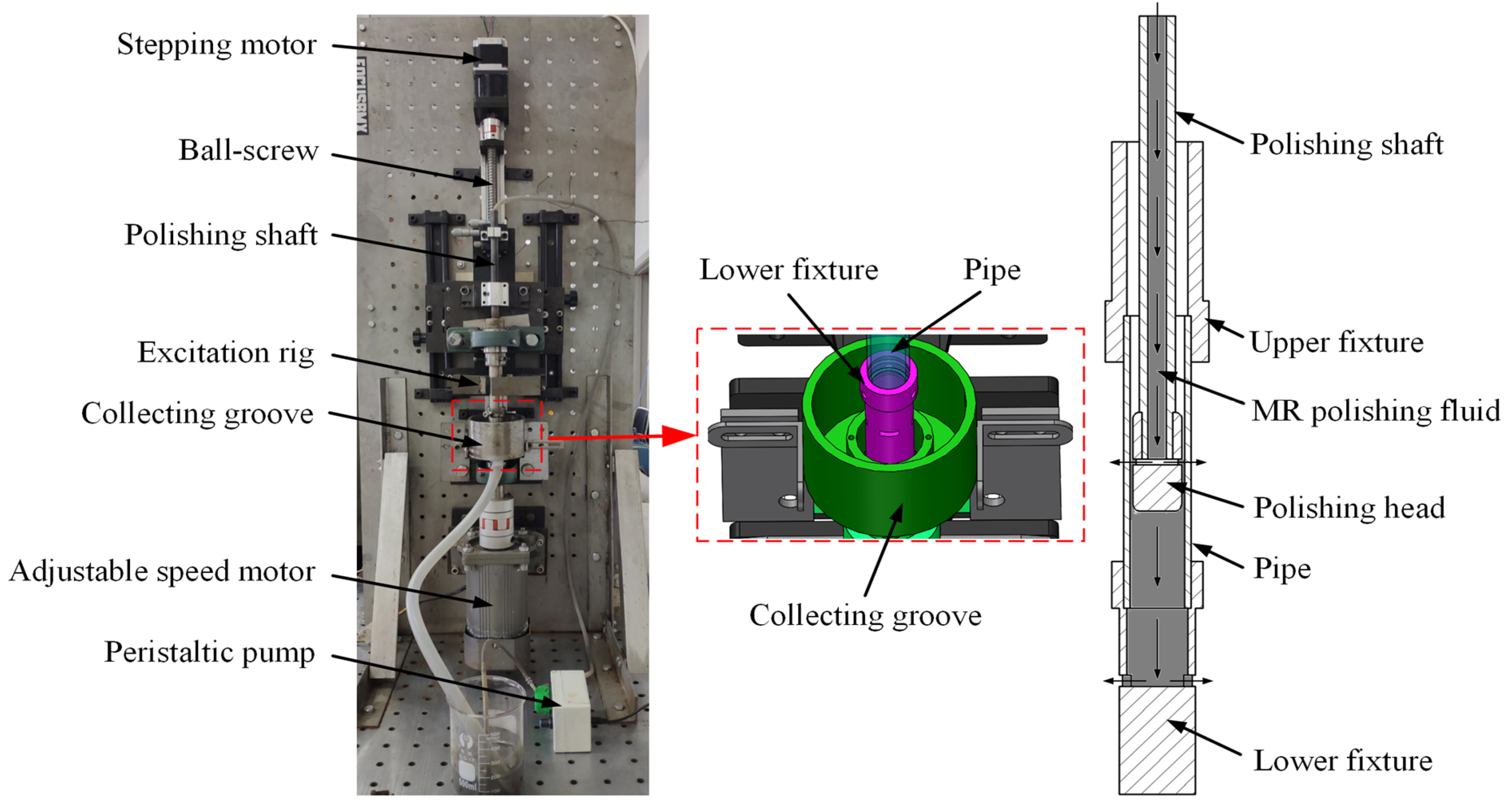
In this work, a new type of VMRP apparatus was designed to further improve the operational stability of the original apparatus to reduce the vibration and noise in the operational process, and hence improve the polishing performance. The VMRP apparatus and its circulation diagram of the MR polishing fluid are presented in Figure 3. The MR polishing fluid flows from the polishing shaft to the polishing head and flows out from the rectangular hole of the polishing head. A portion of MR polishing fluid is stiffened under the action of the magnetic field and adheres to the polishing head. At the same time, the remaining MR polishing fluid enters the lower fixture and is thrown out of the rectangular hole by the high-speed rotating fixture. Then, it flows out of the hole at the bottom of the collecting groove and is finally collected and reused. Furthermore, by controlling the inflow and outflow speed of MR polishing fluid, the MR polishing fluid can maintain a relatively stable height in the pipe and the pipe rotates at a high speed. Then, the polishing head is inserted into the MR polishing fluid, which can make the MR polishing fluid in the pipe more uniform and, hence, reduce the particle deposition.
2.3. Design and Simulation of the Magnetic Field
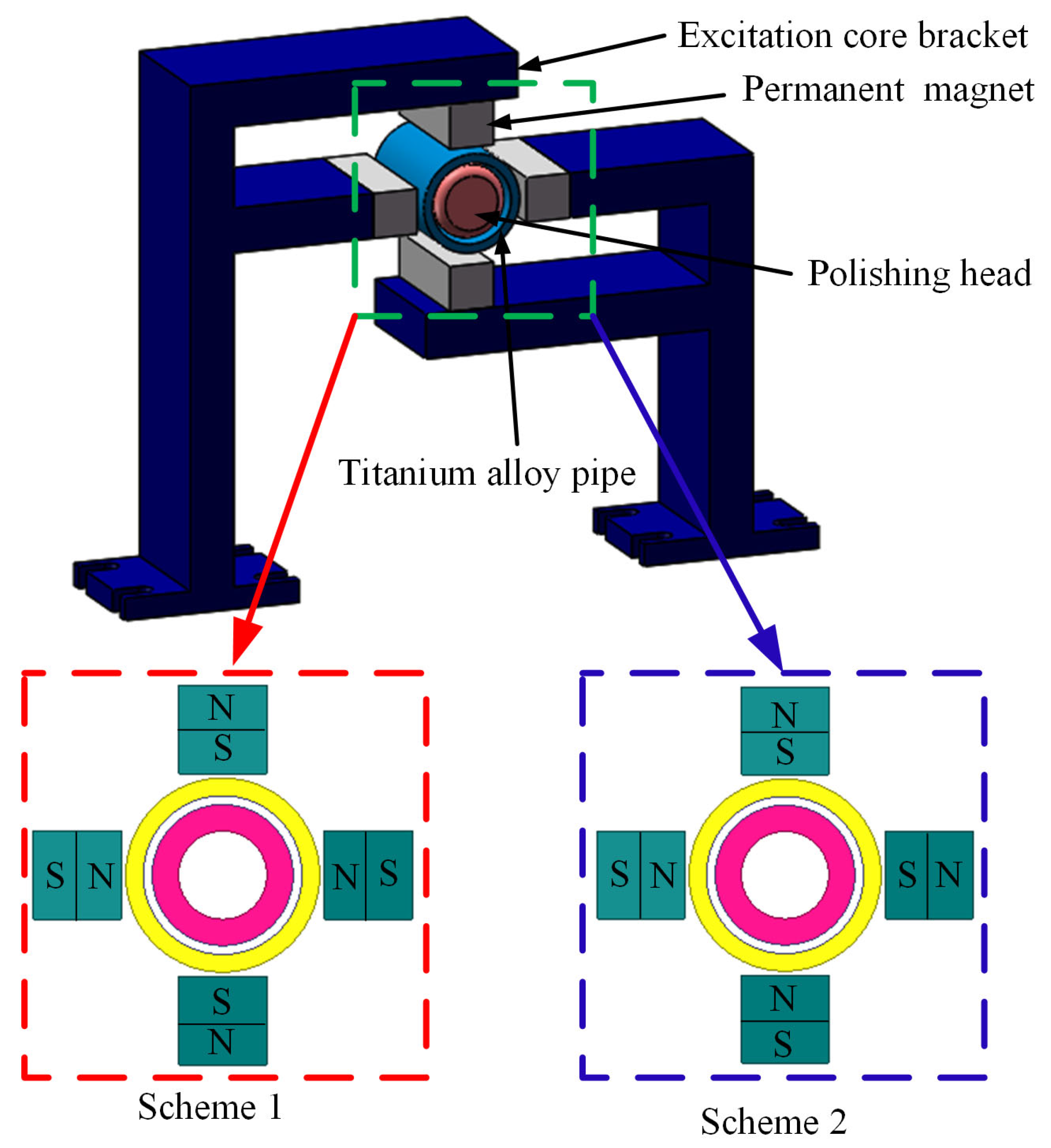
The magnetic field was provided by the permanent magnet, which was symmetrically arranged along the section of the titanium alloy pipe to obtain multiple polishing areas. The diagram of the magnetic field assignment is shown in Figure 4. The arrangements of the permanent magnet were divided into two schemes. In scheme 1, the opposite poles had the same polarity, and in scheme 2, the opposite poles had opposite polarity. To investigate the effect of different working gaps on the distribution of the magnetic field and the magnetic field strength in the polishing area under different magnetic field arrangements, the simulation for the static magnetic field of the excitation device is carried out using Ansoft Maxwell finite element software. The working gap is the distance between the permanent magnet and the external surface of the titanium alloy pipe, which is set as 1 mm to observe the distributions of the magnetic field.
The distributions of the magnetic flux under different assignments are shown in Figure 5. A closed gradient loop was formed inside the excitation core bracket in both schemes. However, outside the exciter core bracket, shown in Figure 5a, each adjacent permanent magnet formed a loop consisting of four closed loops in total; in Figure 5b, only the permanent magnets on the same exciter core bracket formed a loop, forming two closed loops in total. When a closed loop is formed between permanent magnets, theoretically, the polishing area increases with the loops’ increase. Therefore, the polishing area is larger under the opposite side with the same polarity. The magnetic field strength in different working gaps under different schemes is shown in Figure 6. With the increasing working gap, the magnetic flux density of the polishing area decreased gradually. In scheme 1, along with the directions of the magnetic field, the magnetic flux density between two adjacent permanent magnets increased firstly, and then decreased, and finally increased. Moreover, the maximum magnetic flux density of the polishing area decreased from 0.45 T to 0.37 T, and the working gap increased from 0.5 mm to 2 mm, and the magnetic field distribution in the polishing area was relatively uniform. In scheme 2, along with the directions of the magnetic field, the magnetic flux density on the surface of the polishing head increased first and then decreased. Moreover, the maximum magnetic flux density of the polishing area decreased from 0.4 T to 0.2 T, and the working gap increased from 0.5 mm to 2 mm. In practical polishing, there was a certain requirement for the magnitude of magnetic flux density. In scheme 1, the magnetic flux density of the polishing area was larger, and the proportion of the polishing area that satisfied the magnetic flux density was larger than in scheme 2. In scheme 2, although only two closed loops were formed, the magnetic field strength in the polishing head area was stable, and the sensitivity to the working gap was small. In addition, the gradient magnetic field was formed. However, the larger magnetic field strength will lead to the magnetic particles in the MR polishing fluid being completely adsorbed on the polishing head, and the MR polishing fluid in the polishing head cannot flow out. Furthermore, the polishing head was a kind of magnetic material, which would be affected under the action of the magnetic field. Therefore, scheme 1 was selected because four polishing areas formed, which would greatly improve the polishing efficiency, and the working gap of polishing is preferably 1 mm.
3. Experimental Methods
3.1. MR Polishing Fluid
The MR polishing fluid consists of magnetic particles, abrasive particles, carrier liquid, and additives. The CIP is preferable as the magnetizable particle due to its high permeability and low magnetic remnant, and under the magnetic field, the CIP particles align in the magnetic field direction and form a chain structure [23]. The water-based carrier fluid is a preferable option for polishing metal surfaces, and deionized water is selected as the carrier fluid because a hydrated layer can be formed on the workpiece surface [24]. Additives are added to MR polishing fluid to improve its suspension stability. According to the previous research, the diamond abrasive particles with a volume fraction of 10% are more appropriate for polishing titanium alloy pipes [16]. The specific volume fraction of each composition is presented in Table 1.
3.2. Polishing Conditions
A TA2 titanium alloy pipe is used as the workpiece to be polished, which has a length, external diameter, and internal diameter of 100 mm, 22 mm, and 18 mm, respectively. The production process was chosen as cold rolling, and the outer surface was deburred and pickled. Sandpaper was used to grind axially along the internal surface of the titanium alloy pipe before polishing to realize the pretreatment of the pipe, which can remove the oxide layer, surface pits, and other defects on the internal surface and create a good condition for the subsequent MR finishing process. Moreover, for the same test of MR polishing experiments, the specimens with similar initial surface roughness were selected to reduce the deviation of the initial surface roughness. The internal surface of the pipe was polished partially to easily distinguish the polished areas and the unpolished areas. Furthermore, the polishing head is made of a ferromagnetic material, which can ensure that the flow of MR polishing fluid inside the polishing head is not affected by the external magnetic field [16]. The specific polishing conditions are presented in Table 2.
3.3. Experimental Design of the VMRP Process
MR polishing experiments are undertaken without and with the permanent magnetic field to evaluate the polishing performance and efficiency of MR polishing. The yield stress of MR polishing fluid depends on the strength of the magnetic field, the composition of the MR polishing fluid, the particle size, and the particle distribution [25]. Hence, the lower shear stress of MR polishing fluid can be overcome by changing the parameters of the polishing process. Moreover, the experiment is designed according to the method of controlling the variable. Only one of the factors is changed each time, while the other factors are unchanged. By doing this, the influence of the changed factor on the polishing effect can be accurately evaluated. The MR polishing experiments under the VMRP apparatus are divided into three tests, and the total revolutions per test of the pipes are constant in each test. The experiments in Test 1 were conducted to study the effect of different polishing times on the polishing performance. According to the previous horizontal MR polishing experiments, the titanium alloy pipe has the best polishing effect at 700 rpm, and the particle sizes of CIP and diamond powder were 18 μm and 20 μm, respectively [16]. Hence, the rotation speed of the pipe is chosen as 700 rpm, and the polishing time is set as 675, 1350, 2025, and 2700 cycles, respectively. Furthermore, the combined experiments of CIPs and polishing particles of different sizes in Test 2 are conducted at the same polishing time and rotation speed as in Test 1 to investigate the influence of different particle sizes only on the polishing performance. Finally, the combined experiments of different rotation speeds in Test 3 are conducted at the same revolution and particle size as in Test 1 to investigate the influence of different rotation speeds on the polishing performance.
3.4. Measurement of Surface Roughness and Removal Mass
The variation of roughness and removal mass before and after polishing are found to assess the polishing performance. The electronic analytical balance is used to weigh the mass of material removal. The model of the OLS4100 3D laser microscope developed by Olympus Co., Ltd. (Kyoto, Japan) is used to measure the variation of the surface roughness of the internal surface of the titanium alloy pipe. The mass and roughness of pipes before and after polishing are then compared and corrected with the standard part prepared in advance. Moreover, the measurements before and after polishing in each test were carried out three times to take the average value to reduce the deviation.
4. Results and Discussion
4.1. Test 1: Effect of the Polishing Time on the Polishing Performance
Experiments to investigate the polishing performance using the VMRP apparatus were carried out after 675, 1350, 2025, and 2700 cycles, respectively. The settings of specific experimental parameters are given in Table 3. The internal surface and surface topography are shown in Figure 7. For the internal surface of the pipe, after 675 and 1350 cycles, the polished areas only had a metallic matte texture. After 2025 cycles, the polished area showed a specular metallic luster. After 2700 cycles, the surface finish of the polishing area was not significantly improved. For the surface topography, after 2025 cycles, the surface finish of the pipe was high. However, the deep initial axial scratches and slight removal traces of polishing particles were left on the surface of the pipe. After 2700 cycles, the depth of the remaining initial axial scratches further decreased, and the surface finish of the pipe had been greatly improved. However, the polished surface was mostly covered with the removal traces of polishing particles cutting along the circumferential direction. The main issue that affected the surface finish had been changed from the initial scratches to the removal traces of polishing particles.
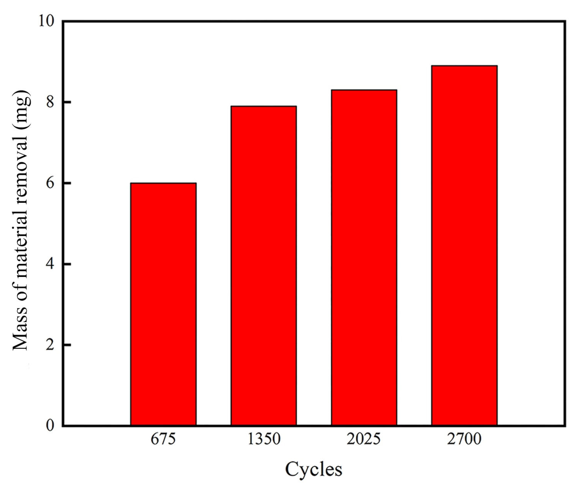
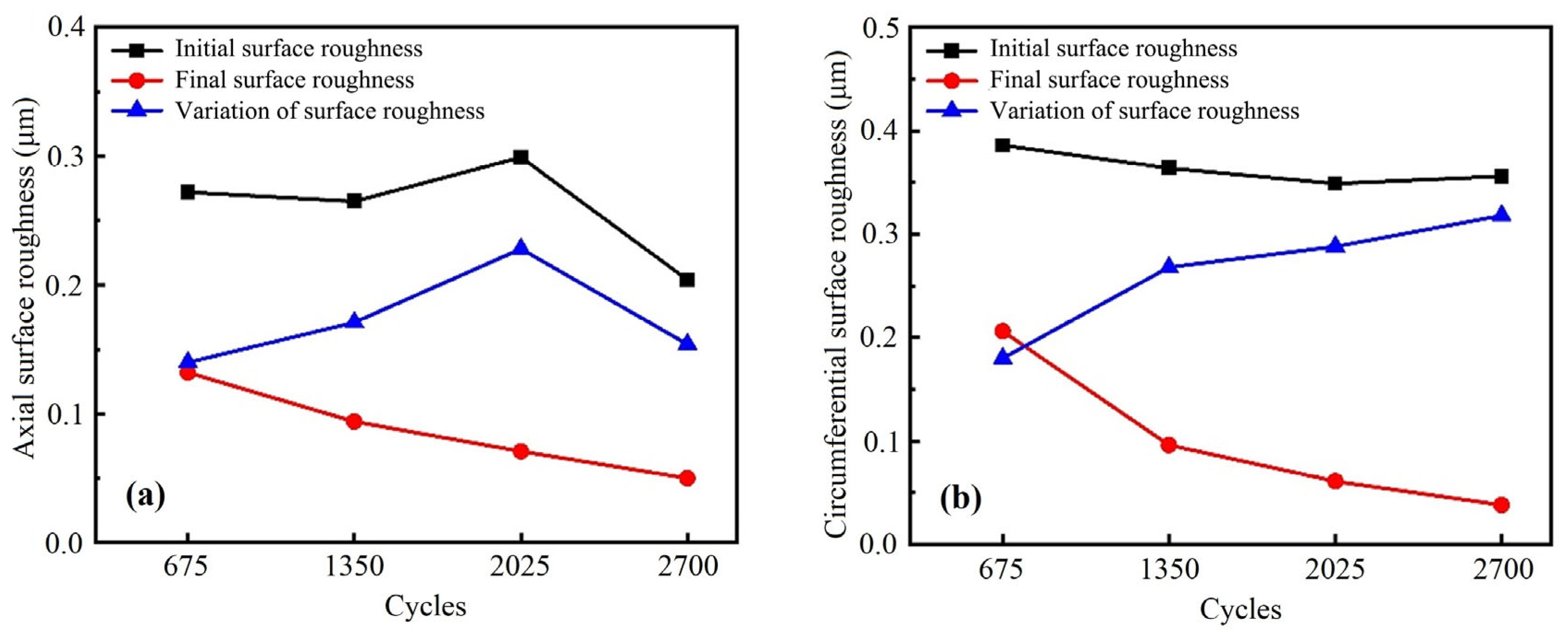
The axial surface roughness and circumferential surface roughness of pipes are shown in Figure 8. As shown in Figure 8a, the average initial axial surface roughness of the pipe is about 0.23 μm. When the polishing time was 675 cycles, 1350 cycles, 2025 cycles, and 2700 cycles, the final axial surface roughness of the internal surface of the pipe was 0.112 μm, 0.093 μm, 0.079 μm, and 0.081 μm, respectively. The final axial surface roughness of the pipe continues to decrease before reaching 2025 cycles, and it remains at a relatively stable value after 2700 cycles. In the early stage of polishing, the final axial surface roughness decreases rapidly. As the polishing time further increases, the material removal efficiency is reduced. This is because in the early stage of polishing, most of the tips of convex peaks on the internal surface of the workpiece are first removed by polishing particles, which makes the polishing efficiency faster. When the polishing time is further increased, more material needs to be removed to smooth the remaining convex peaks and deep pits on the internal surface to decrease the surface roughness after the tips of convex peaks are removed. Moreover, the circumferential removal traces caused by the cutting movement of the polishing particles were left on the polished surface, and the final axial surface roughness was mainly determined by the circumferential removal traces. As shown in Figure 8b, the average initial circumferential surface roughness of the pipe is 0.3 μm. When the polishing time was 675 cycles, 1350 cycles, 2025 cycles, and 2700 cycles, the final circumferential surface roughness of the internal surface of the pipe was 0.173 μm, 0.146 μm, 0.098 μm, and 0.07 μm, respectively. When the polishing time gradually increased, the final circumferential surface roughness of the pipe continued to decrease. In the early stage of polishing, the tips of convex peaks on the workpiece surface are first removed, and the final circumferential surface roughness decreases rapidly. With increasing cycles, the depth of the axial scratches gradually decreased, and the final circumferential surface roughness was mainly determined by the depth of the axial scratches. After 2700 cycles, the final axial surface roughness was greater than the final circumferential surface roughness. The main reason for this is that the circumferential removal traces of polishing particles affected the axial surface roughness. Furthermore, the variation of the surface roughness gradually increases with increasing cycles in Figure 8a,b. As the polishing time gradually increases, the amount of material removal on the surface of the workpiece also gradually increases. Therefore, under the similar initial surface roughness condition, the variation of the surface roughness gradually increases. The mass of material removal is shown in Figure 9. The mass of material removal increases with increasing revolutions, but the material removal rate increases first and then decreases because in the early stage of polishing the convex peaks on the surface are removed rapidly, and in the later stage of polishing, removing the material on the polished surface is more difficult.
4.2. Test 2: Effect of the Particle Size on the Polishing Performance
Experiments to investigate the polishing performance under different size combinations of particles were conducted after 675, 1350, 2025, and 2700 cycles, respectively. The settings of the specific experimental parameters are given in Table 4. The particle size combinations of CIP and polishing particles were 18 μm and 20 μm, 10 μm and 10 μm, and 5 μm and 5 μm, respectively. The internal surface and surface topography are shown in Figure 10. It can be seen from the internal surface of pipes that the polishing effect of the internal surface gradually improved with the continuous increase of the polishing time. After 675 cycles, the polished area with different size combinations of particles develop a metallic luster. Moreover, the metallic luster was more significant with increasing cycles, and the polishing effect was the best after 2700 cycles. Compared with the Test 1 with the particles of a single size, the introduction of a combination of smaller CIP and polishing particles further improved the removal traces caused by the original polishing particles of a single size, and the surface finish of the pipe has been significantly improved. Furthermore, it can be seen from the surface topography of pipes that, compared with Test 1, the depth of the initial axial scratches significantly decreased after 2025 cycles, and the circumferential removal traces were more uniform. This is because smaller polishing particles not only decreased the depth of the initial scratches by removing the surface material but also improved the removal traces of larger polishing particles. After 2700 cycles, the surface finish was greatly improved and the depth of the initial axial scratches further decreased, and only a few removal traces were left on the polished surface.
The axial surface roughness and circumferential surface roughness of pipes are presented in Figure 11. The average initial axial and circumferential surface roughness of the pipes were approximately 0.25 μm and 0.36 μm, respectively, which were close to the initial surface roughness of Test 1. When the polishing times were 675 cycles, 1350 cycles, 2025 cycles, and 2700 cycles, the final axial surface roughness of the pipes were 0.132 μm, 0.094 μm, 0.071 μm, and 0.05 μm, respectively, and the final circumferential surface roughness of the pipes were 0.206 μm, 0.096 μm, 0.061 μm, and 0.038 μm, respectively. It can be seen that when the polishing time gradually increased, the final axial and circumferential surface roughness of the pipe continued to decreased. It is known that the larger polishing particles dominated the removal of the tips of convex peaks on the workpiece surface in the early stage of the polishing process. Thus, it could effectively remove the marks formed on the inner surface of the pipe with the increasing polishing time. Then, the smaller polishing particles could significantly remove the polishing traces introduced by the larger polishing particles [18]. Incidentally, the initial surface roughness of the pipe was low, under 2700 cycles, and the polishing effect of larger particles was not very obvious, and thus the variation of the surface roughness showed a decreasing trend. While the removal effect of smaller particles was more significant, the axial and circumferential surface roughness was still smaller. The mass of material removal is shown in Figure 12. It is observed that the total material removal gradually increased with the increasing polishing time, which is consistent with the change in surface roughness. With the removal of surface protrusions and surface materials, the relative depth of scratches and the pits gradually decreased, and the surface roughness also continues to decrease.
4.3. Test 3: Effect of the Rotation Speed on the Polishing Performance
Experiments to investigate the polishing performance are conducted under different rotation speeds of 1120 r/min, 980 r/min, 840 r/min, 700 r/min, respectively. The settings of specific experimental parameters are given in Table 5. Because of the increase in the rotation speed in Test 3, the same revolutions can be obtained with a lower polishing time, and the total revolutions of Test 3 in each rotation speed combination should be consistent with Test 1 and Test 2. The internal surface and surface topography are shown in Figure 13. For the internal surface of pipes, the polishing effect of the pipe polished is not much different in Test 1 and Test 3. The internal surface of the pipe polished in Test 3 already had a metallic specular effect for 126,000 revolutions, while the pipe polished in Test 1 only had a metallic matte texture. After 189,000 revolutions, although the polished pipe had a metallic specular effect in Test 1 and 3, the polishing effect of the pipe was better in Test 3, and the polishing time was shorter. For the surface topography, the original shallow axial scratches were completely removed after 126,000 revolutions in Test 3, and the deeper axial scratches gradually became shallow, and only the slight material removal traces were left by the polishing particles. Compared with the surface topography of the pipe polished in Test 1 after 252,000 revolutions, the pipe polished in Test 3 was polished to a better degree, with only 126,000 revolutions, which greatly shortens the polishing time and improves the polishing efficiency. However, the surface topography polished in Test 3 after 252,000 revolutions was the worst. This is because the excessive removal of polishing particles damaged the polishing surface. Moreover, lots of removal traces are left on the workpiece surface by the large polishing particles in the later stage of polishing under polishing with a higher rotation speed.
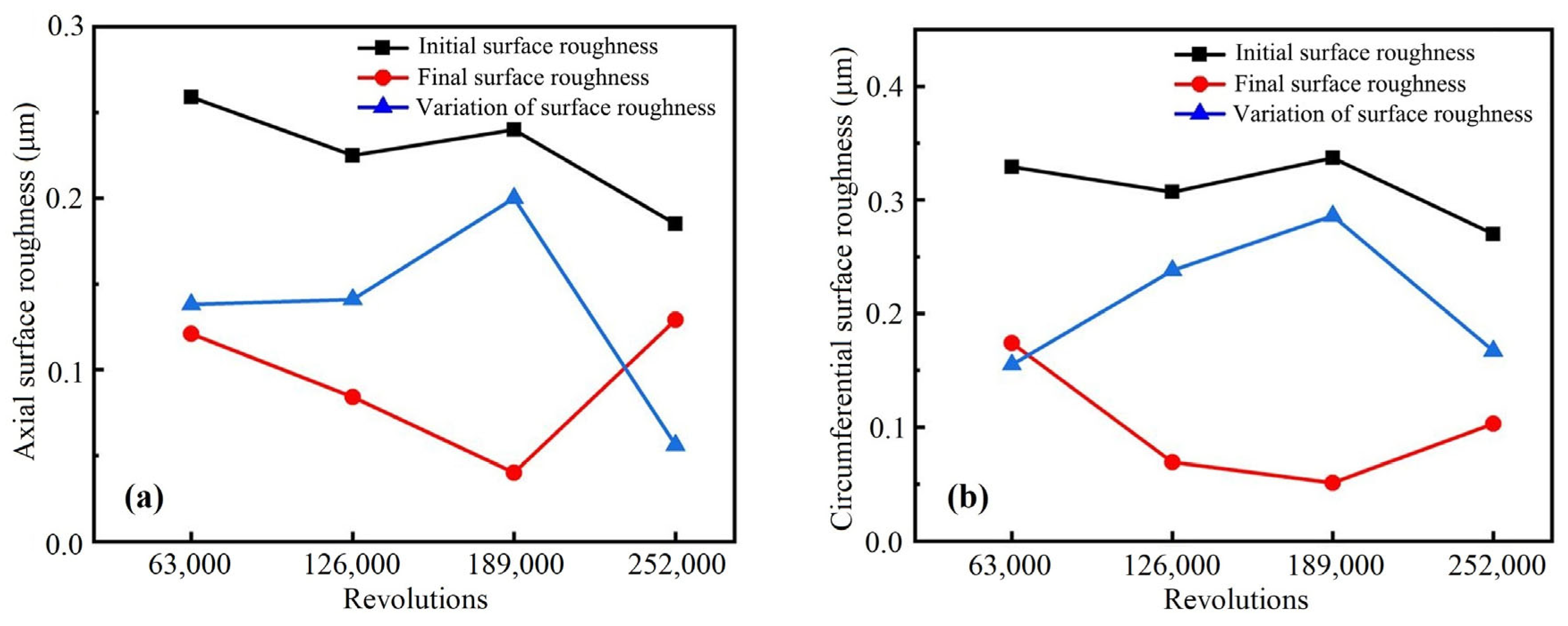
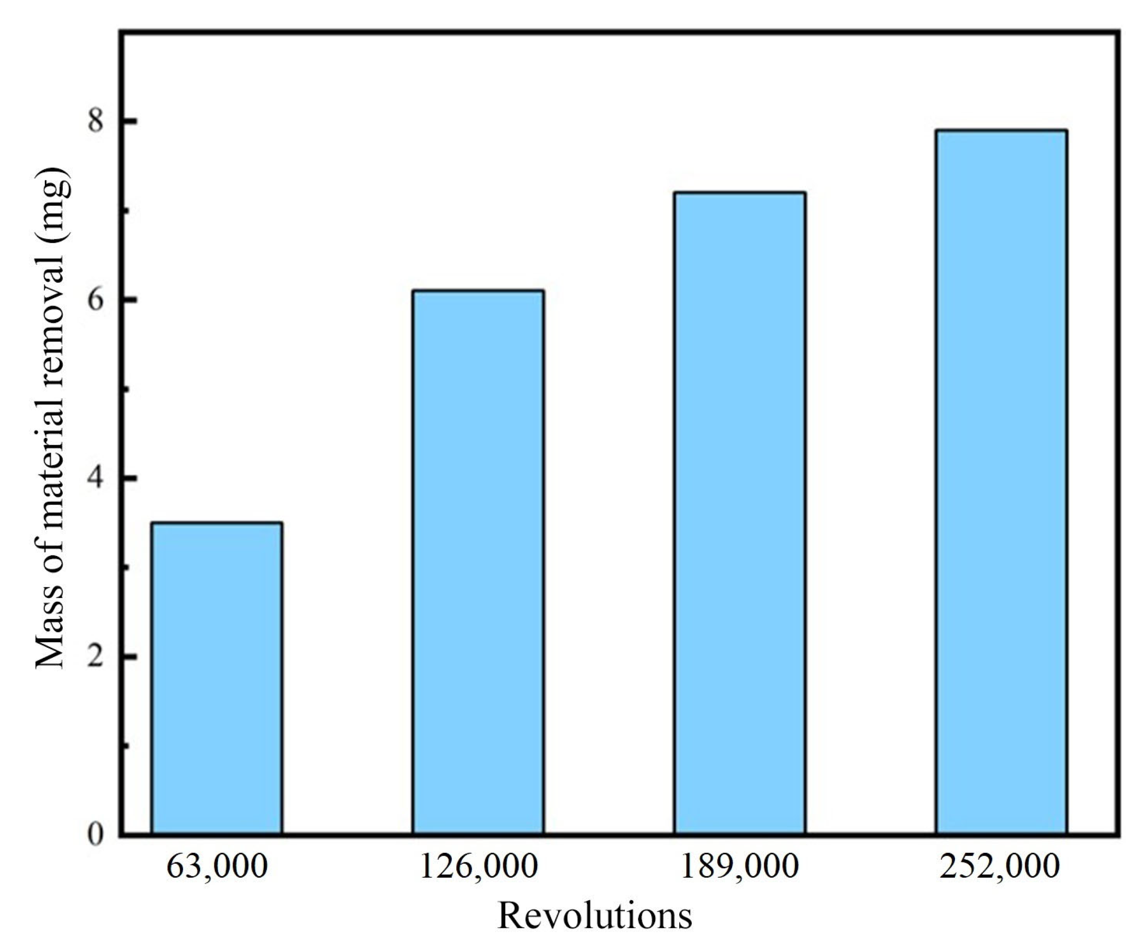
The axial surface roughness and circumferential surface roughness are presented in Figure 14. The average initial axial and circumferential surface roughness of the pipe were approximately 0.24 μm and 0.31 μm, respectively, which was close to the initial surface roughness of Test 1. When the revolutions were 63,000, 126,000, 189,000, and 252,000, the final axial surface roughness of the pipe were 0.121 μm, 0.084 μm, 0.04 μm, and 0.129 μm, respectively, and the final circumferential surface roughness of the pipe were 0.174 μm, 0.066 μm, 0.045 μm, and 0.109 μm, respectively. It is observed that when the polishing time gradually increased, the final axial and circumferential surface roughness of the pipe decreased rapidly to a minimum value, but increased after 252,000 revolutions. After 63,000 revolutions, the final axial and circumferential surface roughness polished in Test 3 was close to the surface roughness polished in Test 1. After 126,000 and 189,000 revolutions, the final axial and circumferential surface roughness of the pipes polished in Test 3 decreased to a lower value compared with the pipe polished in Test 1. This was attributed to the material removal and, hence, increased with the increasing rotation speed of the pipe in unit time. However, the final axial and circumferential surface roughness of the tubes in Test 3 significantly increased for 252,000 revolutions. This phenomenon is explained by the fact that the precise polishing ability of the MR polishing fluid significantly decreased as the temperature of the polishing area increased under long-term high-speed rotation conditions. And, the complex wear phenomena occurred in the polishing area. From Figure 13, it is also seen that the circumferential wear marks left on the polished surface were extremely dense, which becomes the main factor affecting the axial and circumferential surface roughness, and this is consistent with the trend of surface roughness variation shown in Figure 14. The mass of material removal is shown in Figure 15. It is identified from this result that the polishing process achieved better material removal under the combined rotational speed, and the removal amount gradually increased with the increase of revolutions. In the early stage of polishing, the surface protrusions could be easily removed under the higher motor speed, and the removal amount also gradually increased; in the later stage of polishing, the inner surface of the pipe was relatively flat, and the material removal was relatively difficult to rely on for polishing particles to press into the polished surface [17]. Meanwhile, the motor speed was low, and the amount of material removal decreased accordingly. The combined polishing process using multiple motor rotation speeds greatly improved the polishing efficiency. Moreover, compared with the polishing effect polished in Test 1 after 2700 cycles, it is calculated that the combination of different rotation speeds can achieve the same or an even better polishing effect after 1602 cycles under the same revolutions. In short, the optimal axial surface roughness of 0.04 μm for the polished inner surface was achieved using the VMRP approach in this study. It is here noted that the axial surface roughness using the horizontal MR polishing apparatus was identified as 0.401 μm [16], which is much larger than the value obtained in this work. In addition, it has been found that although the initial surface roughness of the pipes is different for two types of apparatus, there is a significant improvement in the changes of the surface roughness from 47.85% to 83.34%, demonstrating the better polishing efficiency in MR polishing technology.
5. Conclusions
In this paper, the VMRP apparatus were designed to overcome the structural limitations of the previous horizontal MR polishing apparatus, and hence improve the polishing performance further. The main technical results achieved from this experimental work are summarized as follows: (1) A vertical MR polishing method was formulated based on the principle of MR polishing and experimentally realized to improve the change of surface roughness from 47.85% to 83.34% by reducing unwanted vibration and noise during operation compared to the previous horizontal MR polishing apparatus. (2) It was found from finite element software that the permanent magnet with circumferential distribution can form four magnetic induction line circuits under the opposite polarity arrangement scheme. In addition, the polishing area becomes larger, and hence the magnetic field strength meets the polishing requirements for the magnetic field of the excitation rig. (3) The experiment results obtained from the proposed polishing VMRP apparatus showed a nanoscale polishing surface quality of 0.04 μm in the axial and horizontal directions. (4) Under the same 2700 cycle polishing time, a polishing process combining rough and fine polishing was achieved by changing the combination of different particle diameters, which results in a better circumferential surface roughness of 0.038 μm. (5) Under the same revolutions, higher precision axial surface roughness of 0.04 μm–0.045 μm has been obtained through a combination of high- and low-speed polishing processes after 1602 cycles, which also demonstrates the better polishing efficiency using the proposed polishing process tester and approach.
Consequently, this study verifies the feasibility of the VMRP polishing process, and provides high-quality and efficient MR polishing for the inner surface of titanium alloy pipes. However, the optimal polishing surface quality and polishing efficiency of MR polishing technology needs to be systematically investigated under the coupling effect of magnetic field strength, particle combination, and speed combination in future. Furthermore, the theoretical or analytical constitutive model associated with the experimental coefficients, which can predict the polishing performance, is required to be formulated using deep learning, neural networks, a fuzzy technique, and algorithms to enhance polishing technology using MR fluids.
Author Contributions
Conceptualization, W.S., N.W. and S.-B.C.; methodology, W.S. and S.-B.C.; validation, W.S., Z.Y. and D.M.; formal analysis, W.S. and S.-B.C.; investigation, W.S., N.W. and S.-B.C.; resources, W.S., N.W. and S.-B.C.; data curation, W.S., Z.Y. and D.M.; writing—original draft preparation, W.S., Z.Y., D.M. and S.-B.C.; writing—review and editing, W.S. and S.-B.C.; visualization, W.S. and S.-B.C.; supervision, W.S.; project administration, W.S. All authors have read and agreed to the published version of the manuscript.
Funding
This project was supported by the National Natural Science Foundation of China (Grant No. 52005085).
Data Availability Statement
The data used to support the findings of this study are included in the manuscript.
Conflicts of Interest
The authors declare no conflicts of interest.
References
- Cui, C.X.; Hu, B.M.; Zhao, L.C.; Liu, S.J. Titanium alloy production technology, market prospects and industry development. Mater. Des. 2011, 32, 1684–1691. [Google Scholar] [CrossRef]
- Jain, V.K. Abrasive-based nano-finishing techniques: An overview. Mach. Sci. Technol. 2008, 12, 257–294. [Google Scholar] [CrossRef]
- Sidpara, A.; Jain, V.K. Analysis of forces on the freeform surface in magnetorheological fluid based finishing process. Int. J. Mach. Tools Manuf. 2013, 69, 1–10. [Google Scholar] [CrossRef]
- Nie, M.; Cao, J.G.; Li, J.Y.; Fu, M.H. Magnet arrangements in a magnetic field generator for magnetorheological finishing. Int. J. Mech. Sci. 2019, 161, 105018. [Google Scholar] [CrossRef]
- Grover, V.; Singh, A.K. Modelling of surface roughness in a new magnetorheological honing process for internal finishing of cylindrical workpieces. Int. J. Mech. Sci. 2018, 144, 679–695. [Google Scholar] [CrossRef]
- Singh, A.K.; Jha, S.; Pandey, P.M. Design and development of nanofinishing process for 3D surfaces using ball end MR finishing tool. Int. J. Mach. Tools Manuf. 2011, 51, 142–151. [Google Scholar] [CrossRef]
- Singh, A.K.; Jha, S.; Pandey, P.M. Nanofinishing of a typical 3D ferromagnetic workpiece using ball end magnetorheological finishing process. Int. J. Mach. Tools Manuf. 2012, 63, 21–31. [Google Scholar] [CrossRef]
- Jung, B.; Jang, K.I.; Min, B.K.; Lee, S.J.; Seok, J. Magnetorheological finishing process for hard materials using sintered iron-CNT compound abrasives. Int. J. Mach. Tools Manuf. 2009, 49, 407–418. [Google Scholar] [CrossRef]
- Barman, A.; Das, M. Nano-finishing of bio-titanium alloy to generate different surface morphologies by changing magnetorheological polishing fluid compositions. Precis. Eng.-J. Int.Soc. Precis. Eng. Nanotechnol. 2018, 51, 145–152. [Google Scholar] [CrossRef]
- Luo, B.; Yan, Q.S.; Huang, Z.L.; Pan, J.S.; Fu, Y.Z. Machining method for controlling the behaviours of bingham fluids in cluster magnetorheological polishing pads. Smart. Mater. Struct. 2021, 30, 025002. [Google Scholar] [CrossRef]
- Wang, Y.; Hu, D.J.; Deng, Q.L. Study on internal magnetic abrasive finishing of thin and long austenitic stainless steel tube. Key Eng. Mater. 2004, 259–252, 620–625. [Google Scholar] [CrossRef]
- Zou, Y.H.; Shinmura, A.T. A New internal magnetic field assisted machining process using a magnetic machining jig-machining characteristics of inside finishing of a SUS304 stainless steel tube. Ultra-Precis. Mach. Technol. 2009, 69–70, 143–147. [Google Scholar] [CrossRef]
- Kang, J.M.; George, A.; Yamaguchi, H. High-speed internal finishing of capillary tubes by magnetic abrasive finishing. In Proceedings of the Fifth CIRP Conference on high Performance Cutting 2012, Zurich, Switzerland, 4–7 June 2012; Volume 1, pp. 414–418. [Google Scholar]
- Sadiq, A.; Shunmugam, M.S. A novel method to improve finish on non-magnetic surfaces in magneto-rheological abrasive honing process. Tribol. Int. 2010, 43, 1122–1126. [Google Scholar] [CrossRef]
- Grover, V.; Singh, A.K. A novel magnetorheological honing process for nano-finishing of variable cylindrical internal surfaces. Mater. Manuf. Process. 2017, 32, 573–580. [Google Scholar] [CrossRef]
- Song, W.L.; Peng, Z.; Li, P.F.; Shi, P.; Choi, S.B. Annular surface micromachining of titanium tubes using a magnetorheological polishing technique. Micromachines 2020, 11, 314. [Google Scholar] [CrossRef] [PubMed]
- Peng, Z.; Song, W.L.; Ye, C.L.; Shi, P.; Choi, S.B. Model establishment of surface roughness and experimental investigation on magnetorheological finishing for polishing the internal surface of titanium alloy tubes. J. Intell. Mater. Syst. Struct. 2021, 32, 1278–1289. [Google Scholar] [CrossRef]
- Song, W.L.; Peng, Z.; Pang, S.; Shan, K.; Gao, J.W.; Choi, S.B. Particle-chain evolution and constitutive model of magnetorheological polishing fluids based on hexagonal close-packed structure. Smart. Mater. Struct. 2020, 29, 045012. [Google Scholar] [CrossRef]
- Shorey, A.B.; Jacobs, S.D.; Kordonski, W.I.; Gans, R.F. Experiments and observations regarding the mechanisms of glass removal in magnetorheological finishing. Appl. Opt. 2001, 40, 20–33. [Google Scholar] [CrossRef]
- Yang, J.; Yan, H.; Wang, X.M.; Hu, Z.D. Enhanced yield stress of magnetorheological fluids with dimer acid. Mater. Lett. 2016, 167, 27–29. [Google Scholar] [CrossRef]
- Saraswathamma, K.; Jha, S.; Rao, P.V. Rheological behaviour of magnetorheological polishing fluid for Si polishing. Mater. Today-Proc. 2017, 4, 1478–1491. [Google Scholar] [CrossRef]
- Mutalib, N.A.; Ismail, I.; Soffie, S.M.; Aqida, S.N. Magnetorheological finishing on metal surface: A review. IOP Conf. Ser. Mater. Sci. Eng. 2019, 469, 012092. [Google Scholar] [CrossRef]
- Rahim, M.S.A.; Ismail, I. Review of magnetorheological fluids and nanofluids thermal behaviour. IOP Conf. Ser. Mater. Sci. Eng. 2015, 100, 012040. [Google Scholar] [CrossRef]
- Sidpara, A.; Jain, V.K. Effect of fluid composition on nanofinishing of single-crystal silicon by magnetic field-assisted finishing process. Int. J. Adv. Manuf. Technol. 2011, 55, 243–252. [Google Scholar] [CrossRef]
- Elizabeth Premalatha, S.; Chokkalingam, R.; Mahendran, M. Magneto Mechanical Properties of Iron Based MR Fluids. Am. J. Polym. Sci. 2012, 2, 50–55. [Google Scholar] [CrossRef]
Figure 1.
Schematic diagram of honing MR polishing principle.

Figure 2.
Chain structure of MR fluid and MR polishing fluid.

Figure 3.
Photograph and schematic diagram of the VMRP apparatus.

Figure 4.
Diagram of the magnetic field assignment.

Figure 5.
Distributions of the magnetic flux under different assignments.

Figure 6.
Simulation of the magnetic field strength in different working gaps for different schemes.
Figure 6.
Simulation of the magnetic field strength in different working gaps for different schemes.

Figure 7.
The internal surface and surface topography of pipes under different polishing times.

Figure 8.
The surface roughness of pipes under different polishing times: (a) axial surface roughness, (b) circumferential surface roughness.
Figure 8.
The surface roughness of pipes under different polishing times: (a) axial surface roughness, (b) circumferential surface roughness.

Figure 9.
The mass of material removal of pipes under different polishing times.

Figure 10.
The internal surface and surface topographies of pipes under different size combinations of particles.
Figure 10.
The internal surface and surface topographies of pipes under different size combinations of particles.

Figure 11.
The surface roughness of pipes under different size combinations of particles: (a) axial surface roughness, (b) circumferential surface roughness.
Figure 11.
The surface roughness of pipes under different size combinations of particles: (a) axial surface roughness, (b) circumferential surface roughness.

Figure 12.
The mass of material removal of pipes under different size combinations of particles.

Figure 13.
The internal surface and surface topography of pipes under rotation speed combinations.

Figure 14.
The surface roughness of pipes under rotation speed combinations: (a) axial surface roughness, (b) circumferential surface roughness.
Figure 14.
The surface roughness of pipes under rotation speed combinations: (a) axial surface roughness, (b) circumferential surface roughness.

Figure 15.
The mass of material removal of pipes under rotation speed combinations.


Table 1.
The proportion of composition of MR polishing fluid.
| Constituents of MR Polishing Fluid | Concentration (%) |
|---|---|
| Carbonyl iron powder | 30 |
| Diamond powder | 10 |
| Glycerol | 8 |
| Deionized water | 52 |
Table 2.
Polishing conditions.
| Parameter | Values |
|---|---|
| Polishing gap | 1 mm |
| Reciprocating stroke | 10 mm |
| Reciprocating linear speed | 7.5 cycles per minutes |
| Feeding speed | 2.5 mm/s |
Table 3.
Test 1: experiments with different polishing times.
| Rotation Speed (rpm) | Size of CIP and Polishing Particles (μm) | Polishing Time (Cycles) | Revolutions (r) |
|---|---|---|---|
| 700 | 18 and 20 | 675 | 63,000 |
| 1350 | 126,000 | ||
| 2025 | 189,000 | ||
| 2700 | 252,000 |
Table 4.
Test 2: experiments with different particle sizes.
| Rotation Speed (rpm) | The Polishing Time under Different Sizes of Particles (Cycles) | Revolutions (r) | ||
|---|---|---|---|---|
| 18 μm and 20 μm | 10 μm and 10 μm | 5 μm and 5 μm | ||
| 700 | 225 | 225 | 225 | 63,000 |
| 450 | 450 | 450 | 126,000 | |
| 675 | 675 | 675 | 189,000 | |
| 900 | 900 | 900 | 252,000 | |
Table 5.
Test 3: experiments with different rotation speeds.
| CIP and Polishing Particles (μm) | The Polishing Time under Different Rotation Speeds (Cycles) | Revolutions (r) | |||
|---|---|---|---|---|---|
| 1120 rpm | 980 rpm | 840 rpm | 700 rpm | ||
| 18 and 20 | 105 | 120 | 140 | 169 | 63,000 |
| 210 | 240 | 280 | 338 | 126,000 | |
| 315 | 360 | 420 | 507 | 189,000 | |
| 420 | 480 | 560 | 676 | 252,000 | |
Disclaimer/Publisher’s Note: The statements, opinions and data contained in all publications are solely those of the individual author(s) and contributor(s) and not of MDPI and/or the editor(s). MDPI and/or the editor(s) disclaim responsibility for any injury to people or property resulting from any ideas, methods, instructions or products referred to in the content. |
© 2024 by the authors. Licensee MDPI, Basel, Switzerland. This article is an open access article distributed under the terms and conditions of the Creative Commons Attribution (CC BY) license (https://creativecommons.org/licenses/by/4.0/).
Share and Cite
MDPI and ACS Style
Song, W.; Yang, Z.; Meng, D.; Wang, N.; Choi, S.-B. Magnetorheological Polishing Based on Honing Vertical Mechanism for Inner Surface of Titanium Alloy Pipes. Lubricants 2024, 12, 86. https://doi.org/10.3390/lubricants12030086
AMA Style
Song W, Yang Z, Meng D, Wang N, Choi S-B. Magnetorheological Polishing Based on Honing Vertical Mechanism for Inner Surface of Titanium Alloy Pipes. Lubricants. 2024; 12(3):86. https://doi.org/10.3390/lubricants12030086
Chicago/Turabian StyleSong, Wanli, Zhen Yang, Dezhi Meng, Na Wang, and Seung-Bok Choi. 2024. "Magnetorheological Polishing Based on Honing Vertical Mechanism for Inner Surface of Titanium Alloy Pipes" Lubricants 12, no. 3: 86. https://doi.org/10.3390/lubricants12030086
Note that from the first issue of 2016, this journal uses article numbers instead of page numbers. See further details here.