Carrying Capacity of Spherical Hydrostatic Bearings including Elastic Deformation
by
 ,
,
Shengdong Zhang
1,* ,
,
Dongjiang Yang
2,
Guangming Li
3,
Yongchao Cheng
3,
Guang Chen
1,
Zhiming Zhang
1 and
Jichao Li
1 1
School of Mechanical and Electrical Engineering, Jining University, Qufu 273199, China
2
Shandong Xinneng Shipbuilding Co., Ltd., Jining 273500, China
3
Wuhan Secondary Institute of Ships, Wuhan 430064, China
*
Author to whom correspondence should be addressed.
Lubricants 2024, 12(3), 97; https://doi.org/10.3390/lubricants12030097
Submission received: 12 February 2024
/
Revised: 8 March 2024
/
Accepted: 12 March 2024
/
Published: 15 March 2024
Abstract
:This paper presents a theoretical model for calculating the carrying capacity of spherical hydrostatic bearings, including the deduction and solution of differential equations for fluid flow in the oil seal and the generation of bearing characteristic parameters. An example is used to verify the accuracy of the proposed calculation model. Additionally, the influence of dynamic pressure on the bearing capacity is investigated under various speed conditions. The results demonstrate that as the minimum width of the oil gap decreases, the maximum dynamic pressure increases non-linearly. Furthermore, the maximum dynamic pressure increases with higher rotational speeds, particularly when the width is smaller.
1. Introduction
Bearings are a critical component of rotating machinery, with a thorough understanding of their behavior being essential for predicting system performance. High speeds, high power, and reliable operation are imperative requirements. Accurate prediction and control of bearing behavior are crucial, as over 40% of machine failures stem from bearing issues. The most effective approach to addressing these problems is through comprehensive analysis, as evidenced by numerous studies that have led to improved performance [1,2,3]. Hydrostatic bearings possess desirable characteristics such as low running friction, minimal viscous dissipation, high load-carrying capacity, and high stiffness, making them essential for heavy-duty industrial applications in modern machinery such as machine tools, precision instruments, hydraulic pumps, motors, telescopes, gyroscopes, dynamometers, radar units, and marine engines. Spherical bearings, in particular, offer advantages over other configurations due to their self-aligning nature and ability to withstand radial and thrust loads without being affected by angular misalignments [4,5,6,7].
Scholars have conducted both theoretical and experimental research on spherical bearings. Mayer [8] and Elescandarany [9] derived the Reynolds governing equation for spherical bearing applications. Kazama [10] proposed an optimal design for fitted and clearance thrust spherical bearings with capillary and orifice restrictors to minimize power losses and enhance stiffness. The study revealed a central pressure ratio of two-thirds for the fitted type and 0.69 for the clearance type. Yacout [11,12,13,14,15] conducted an analytical investigation on both types, incorporating factors such as surface roughness, centripetal inertia, viscosity, and seat configuration to evaluate bearing performance. The central pressure ratio was found to be consistent at two-thirds for both types, indicating reliable bearing performance. Optimal designs emphasizing minimal friction and flow rate were exemplified. Elescandarany [16,17,18] introduced two novel techniques for designing fitted spherical bearings, with and without restrictors. Rajashekar [19] examined the lubricating characteristics of squeeze film, considering surface roughness and force. The influence of roughness and force on bearing lubrication and capacity was analyzed using the Reynolds equation, which incorporated surface roughness and couple stress. The results demonstrated that the bearing capacity increased with higher couple stress. Raghavendra et al. [20] explored the effects of velocity slip and viscosity on squeeze film lubrication in spherical bearings. They derived a modified Reynolds equation to account for these effects and analyzed the pressure distribution and bearing capacity. The results indicated that increased viscosity near the bearing surface improved hydrodynamic lubrication. Tao [21] developed a genetic algorithm for the design of gas-pressure spherical bearings, obtaining optimal results by optimizing the spherical radius and support angle. Guo [22] optimized the design of non-liquid friction spherical plain bearings by optimizing the bearing angle, spherical radius, and oil supply vortex radius. Contact analysis models were established using the finite element method (FEM) to calculate contact pressure, and the results were used to modify design parameters until all requirements were met. Luo [23,24] introduced methods for estimating the static load rating of spherical plain bearings and conducted life tests on new joint bearings using a testing machine. Spherical bearings have also found application in ship engineering [23,24,25,26,27,28,29,30]. Self-aligning ball bearings [30,31,32] were used as axial load bearings in hydrofoil ship cylinder flanges and dynamic load simulation tests. The designed bearing capacity was 500 kN, meeting the requirements of swing oscillation and swing tests. Wang, Qian, Li, and others [33,34,35] used spherical hydrostatic bearings to support the weight of large marine propellers during static balance tests. They analyzed the bearing capacity, leakage, and pressure distribution of the hydrostatic spherical bearings, demonstrating that this method offers high precision, stable performance, and ease of use for static balance testing of large propellers.
Despite extensive research on spherical bearings, there are still some shortcomings, such as the lack of investigation into the effects of eccentric rotation on dynamic pressure distribution. The uneven coupling of dynamic pressure in eccentric states can potentially negatively impact the stable operation of spherical bearings.
2. Mathematical Model
The static pressure spherical bearing consists of a bearing housing and a bearing body, as shown in Figure 1.
2.1. Establishment of Mathematical Model for Carrying Capacity of Hydrostatic Spherical Bearing
The oil film in the spherical bearing can be represented by a narrow gap between the spherical surfaces. The cutting plane is taken as the plane of the axis, with the sphere radius denoted as R. The angle of the high-pressure oil chamber is 2θ1, and the angle of the oil seal on one side is θ2. Under the influence of high-pressure hydraulic oil, the bearing body is suspended in the oil. For simplicity, the study focuses only on the vertical eccentricity of the bearing body, neglecting any horizontal eccentricity. Note the spherical eccentricity of the vertical distance and the resulting oil seal edge as shown in Figure 2.
The gap, h, resulting from the eccentricity of two concentric spheres is determined by the angle, θ, and the spherical radius, R, as depicted in Figure 3.
The relation can be expressed as the following equation.
The spherical coordinate system shown in Figure 4 is established in the spherical bearing oil seal model.
Taking the center of the sphere as the origin and the axis of the bearing as the z-axis, the cartesian coordinate system O-xyz is established. Let P be a point in the sphere, the distance from point O to point P is the angle between line segment OP and z-axis, P is the projection of Q on the xOy plane, is the angle between the segment OQ and the x-axis forward. The parameters , θ, form the spherical coordinate of point P. In the model of a spherical bearing with oil seal side, the spherical radius of the bearing body is written as R, and the width of the gap is denoted as h; taking a closed microelement area dA on the spherical surface can be decomposed into a small increment in the spherical , .
In the flow of hydraulic oil, the oil is known as a continuous medium, that is, oil fills the entire oil seal edge gap continuously, and the characteristic of oil can be expressed by continuity equations [36]. In the spherical coordinate system, the continuity equation can be expressed as:
The flow of oil of hydrostatic spherical bearings within the oil gap follows the Navier–Stokes equation. In the spherical coordinate system, the Navier–Stokes equations can be expressed as:
where , , are the mass forces in the direction of , , and is
The continuity equation and the Navier–Stokes equation are mathematical expressions of the law of conservation of mass and momentum for viscous fluid flow, and they have universal applicability. There are four differential equations involving flow-dependent state parameters , , , and . In theory, these equations can be solved, but as of now, a general solution to the equation’s general form has not been obtained. However, in engineering practice, the equations are simplified to obtain the differential equations, and the numerical solution is obtained by combining the initial and boundary conditions [37].
According to the oil flow characteristics studied in this paper, the following assumptions are made for the mathematical model:
- (1)
- The oil density ρ is a constant value.
- (2)
- Mass forces in the oil flow are disregarded, that is, , , ;
- (3)
- The oil flow is constant, and the oil flow in the gap of the sealing edge does not change with time, that is,
- (4)
- Regardless of oil circumferential rotation speed, and ;
- (5)
- Regardless of the radial diffusion of oil flow,
From the above assumptions, the continuity equation can be simplified as:
Navier–Stokes Equations (3)–(5) can be simplified into
Equation (7) can be further simplified into
Substituting Equation (11) into Equations (8)–(10),
According to the simplified equations above, we can know that:
- (1)
- The regularities of radial pressure distribution.
According to Equation (12), the pressure distribution along the radial direction is closely related to the directional velocity. In hydrostatic support in general, the flow rate cannot be too large, so the value is about 104. However, the oil seal angle by the bearing size limit cannot be too large. The value is larger, generally greater than , so >> and, in the calculation, the pressure gradient along the direction can be ignored, that is, the oil pressure along the oil seal edge does not change along the radial direction.
- (2)
- Distribution of axial pressure
According to the above analyses, >> , and Formula (13) can be simplified to:
- (3)
- The distribution of circumferential pressure
According to Equation (14), the pressure gradient along the direction of φ is 0. This means that oil seal edge crack pressure does not change along the circumference.
Equation (15) integrates x twice, yielding:
where: , are undetermined constants.
Substituting the boundary conditions into (16), we obtain:
Plugging Formula (17) into formula (16), we can obtain:
Equation (18) shows the relationship between the radius and the axial flow velocity at an axial pressure gradient in the sealing edge gap.
After calculating axial velocity , we can calculate the oil-sealing side spillage Q. With the axial angle θ, the oil-sealing side spillage Qθ can be expressed as
It is known that the pressure at the inlet of the oil seal is the pressure of the high-pressure oil chamber, and the pressure at the outlet of the oil seal is zero. After calculating the axial pressure gradient at all angles , the pressure at any angle can be calculated by integration to obtain the oil pressure distribution of the sealing side.
The bearing capacity of the static spherical hydrostatic bearing consists of the hydraulic bearing capacity of the high-pressure oil chamber F1, the hydraulic bearing capacity of the seal oil F2, and the fluid friction force of the hydraulic oil F3. Hydraulic bearing capacity F1 and F2 can respectively be expressed as:
where S1 and S2 are respectively high-pressure oil chamber projected areas and sealing edge projection areas.
Internal friction exists in the process of hydraulic oil flow; the resistance can be calculated by Newton’s internal friction law:
On the bearing, the viscous resistance caused by the axial flow of hydraulic oil played an important role. The axial flow friction load F3 of hydraulic oil can be expressed as:
Therefore, the bearing capacity F of the static pressure spherical bearing can be expressed as
2.2. The Calculation for a Mathematical Model of Hydrostatic Spherical Bearing
Using a numerical method to solve the oil seal model of a spherical bearing, the physical model needs to be divided into finite units. The circumferential angle 0~2 of the oil seal is divided into m units. The circumferential step is , node numbers are 1~m. The axial angle is split into n units, the axial step is , node number is . Seal gap thickness h of oil seal is in k discrete units. The thickness step is , node number is .
Equation (18) shows the distribution of the axial flow velocity at one axial pressure gradient in the gap of the oil seal. Equation (19) indicates the oil spill rate . Equations (18) and (19) contain unknown axial pressure gradients , so the key to solving the differential equations of fluid flow is to solve the axial pressure gradient. According to the characteristics of the model, the axial pressure gradient has two constraints.
- (1)
- The flow constraints
Hydraulic oil is regarded as an incompressible fluid, so at different , the oil flow rates calculated by the integration must be equal.
- (2)
- Boundary constraints for pressure distribution
The axial pressure distribution can be determined by integrating the pressure gradient. This presents a boundary value problem, as the pressure at the oil seal inlet must equal the pressure of the high-pressure oil chamber, while the pressure must be zero in the external environment. Consequently, the resulting pressure distribution must satisfy both boundary conditions.
First, spherical size parameters and hydraulic oil parameters were input to determine the high-pressure oil chamber pressure . After the discrete oil seal model was established, the axial pressure gradient at the inlet side of the oil seal was estimated, the axial velocity was calculated, and the inlet flow rate was calculated with the entrance flow. The inlet flow as the spherical bearing oil flow is used to calculate the pressure gradient , , …, at other angles. The high-pressure oil chamber pressure can be considered equal to the inlet pressure . The integral is calculated to calculate the pressure at the oil outlet. According to the pressure distribution boundary value constraint, the outlet pressure should be equal to zero. If is not equal to zero, it is necessary to correct the value of the axial pressure gradient at the inlet of the oil seal and recalculate the pressure distribution as the initial condition. The above procedure is repeated until the outlet pressure equals zero or less than the allowable error and the output axial pressure distribution after the calculation is expected to be completed. Through the above calculation, according to Equation (24), we can calculate the corresponding spherical bearing capacity.
Based on the analysis presented above, the numerical solution flowchart of the differential fluid flow equation of the oil-sealing edge is shown in Figure 5.
3. Results and Discussion
The carrying capacity of the spherical hydrostatic bearing, specifically the one used in the self-aligning ball bearing of a hydrofoil, is evaluated as an example model [32]. The calculation method described earlier is applied to determine the carrying capacity, and the results are compared with empirical values. The basic design parameters for the static pressure spherical bearing are listed in Table 1.
Under typical operating conditions, the average oil film thickness (h) of the spherical hydrostatic bearing is 0.2 mm, with a vertical eccentricity (e) of approximately 0.25 mm. These specific parameters were utilized as inputs in the fluid flow differential equation-solving program. The program divided the system into 360 circumferential meshes, 64 axial meshes, and 20 radial meshes. The outlet pressure error was set at 1 Pa to solve the differential equation. The resulting convergence curve of the outlet pressure is illustrated in Figure 6.
The total bearing capacity of the hydrostatic bearing is calculated in this paper as F = 509 kN. According to the literature [32], the hydrostatic spherical bearing capacity is F = 500 kN. A comparison of the results obtained from these two calculation methods reveals that the bearing capacity calculated by both methods is identical, with a relative error of 1.80%. This demonstrates the effectiveness and rationality of the calculation method and the resulting conclusions.
3.1. Calculation of Elastic Deformation of Bearing Surface
Under light load conditions, the elastic deformation of bearing surfaces is negligible [38]. However, under heavy load conditions, the pressure at the inlet of the high-pressure oil chamber and the oil seal inlet increases, leading to a significant influence of the elastic deformation on the width of the gap. In such cases, the rigidity assumption cannot ignore the width of the gap. Therefore, it is necessary to consider the impact of surface elastic deformation on the bearing’s carrying capacity [39].
The fluid pressure for sealing the oil edge gap is caused by the elastic deformation of the bearing surface. Consequently, the sealing of the gap edge changes, affecting the fluid flow and pressure distribution within the oil seal gap. This presents a coupling problem of fluid–solid interaction for sealing the oil gap [40,41]. Due to the complexity of elastic deformation calculations, a simplified model is required to obtain the equation for elastic deformation calculation.
In the cylindrical coordinate system, there exists a half-space body with its origin subjected to a normal concentrated force F. The point P on the boundary surface is at a distance ρ from the origin, and the deformation occurs in the direction of the body at point P. This is illustrated in Figure 7.
The deformation at any point, except for a hemisphere with a small radius, can be expressed using the elastic mechanics formula.
where: —Poisson’s ratio; —elastic modulus, Pa; F-load, N; —the distance between point P and boundary surface, m.
When the half-space body is subjected to the normal distribution force on the boundary surface, every microarea , force , and the normal displacement of each point on the interface can be obtained by the superposition method.
The deformation of the force at point to point is:
where: —area of microelement, m2; —the distance between two points, m.
The total elastic deformation at point (k, l) is determined by the linear superposition of all point forces acting on points (k, l). The elastic deformation matrix for all points is computed to obtain a four-dimensional matrix with dimensions (m + 1) × (n + 1) × (m + 1) × (n + 1). The resulting matrix records the total elastic deformation coefficients. Upon calculating the pressure distribution of the sealed oil, the elastic deformation coefficient matrix for each point is multiplied by the coordinates of point (k, l) to obtain the total elastic deformation at that point under the applied pressure.
3.2. Coupling Method for Fluid Flow and Surface Elastic Deformation of Oil Seal
Understanding the flow state of the hydraulic oil film at the oil seal is crucial for studying the carrying capacity of a hydrostatic spherical bearing. Since the length of the oil-sealing gap is smaller than the spherical radius, the curvature has minimal impact on the normal elastic deformation. Hence, when calculating the surface’s elastic deformation, the curved surface can be approximated as a plane.
The p area element can be expressed as
Action point P and the force–distance d can be expressed as
Equation (28) holds under the conditions and and, when and , it dropped on the singular point, not the integral solution. Therefore, when and , deformation of the point can be calculated through the interpolation method; to reduce the interpolation error, multiple directions can be taken after the multiple interpolation average method.
The solution to the fluid flow differential equation includes the superimposed elastic deformation of the surface, which is calculated based on the width of the oil seal edge.
Here, h0 represents the thickness of the oil seal gap under the assumption of rigidity, measured in meters. μ1 refers to the elastic deformation of the bearing body surface, also measured in meters. μ2 represents the surface elastic deformation of the bearing, also measured in meters.
In the process of the coupling solution, assuming that , are the i − 1 iterations of the bearing body and the bearing surface during elastic deformation, deformation is added to , then the width of the oil-sealing gap is obtained. The pressure distribution of the oil edge is obtained when the width of the oil gap is calculated. Using the total elastic deformation coefficient matrix calculated above, the amount of surface elastic deformation caused by the pressure distribution is calculated, denoted by , . Compared with the previous two iterations of the deformation of , and , , the amount of deformation error is calculated. In this paper, the maximum value of the difference between the two values of deformation is taken as the criterion to judge the convergence of the deformation, as follows:
This paper gives the allowable error [d] = 0.001 mm and, when du > [du], , are added to rigid edge seal gap thickness , which results in the the new oil seal edge slot width. Iterations are repeated until the deformation error is less than the allowable error. When du < [du], the iterations are stopped, the output edge seal axial pressure distribution is , axial velocity distribution is , flow is , deformation is , . The capacity of hydrostatic spherical bearing parameters is calculated further.
3.3. Influence of Elastic Deformation on Loading Performance Parameters of Bearing
This section investigates the impact of elastic deformation on the carrying capacity of a hydrostatic spherical bearing, using a large hydrostatic spherical bearing as an example. The material parameters for the main components of the bearing are outlined in Table 2.
To examine the impact of surface elastic deformation on bearing performance, the pressure in the high-pressure oil chamber was set at p = 60 MPa, with a vertical eccentricity of e = 0.2 mm. Figure 8 illustrates the convergence curve of the deformation error during the solving process.
The limit values of elastic deformation of bearing parts are calculated and shown in Table 3.
Therefore, the maximum width of the oil seal edge increases, . The minimum increase in the width of the gap at the oil seal is .
The effect of the surface elastic deformation of the spherical bearing on the gap width of the oil seal is shown in Figure 9.
The findings indicate a non-linear decrease in the amount of elastic deformation along the oil seal surface in the direction of hydraulic oil flow [39]. This can be attributed to the higher hydraulic pressure at the inlet of the oil seal, resulting in a greater amount of elastic deformation. Conversely, the hydraulic pressure at the oil seal exit approaches zero, leading to minimal elastic deformation on the bearing surface.
In this study, the load-carrying capacity of the bearing with surface elastic deformation is defined as the percentage increase in the load-bearing characteristic, excluding the effects of surface elastic deformation. A dimensionless quantity is employed to measure the change in bearing carrying capacity after surface elastic deformation. Positive values indicate a relative increase in the capacity, while negative values indicate a relative decrease. The results are presented in Table 4.
Table 4 reveals that considering the elastic deformation of the bearing surface leads to an increase in the bearing capacity of the bearing sealer. However, the bearing capacity of the high-pressure oil chamber remains unchanged, resulting in only a slight overall increase in bearing capacity. Considering the elastic deformation of the bearing surface, the width of the oil seal edge expands, resulting in a noticeable increase in oil flux through the oil seal side and an elevated average flow velocity at the outlet. The increased width of the oil seal edge reduces the rotational friction torque by decreasing the rotation of the bearing body caused by the circumferential velocity gradient of hydraulic oil.
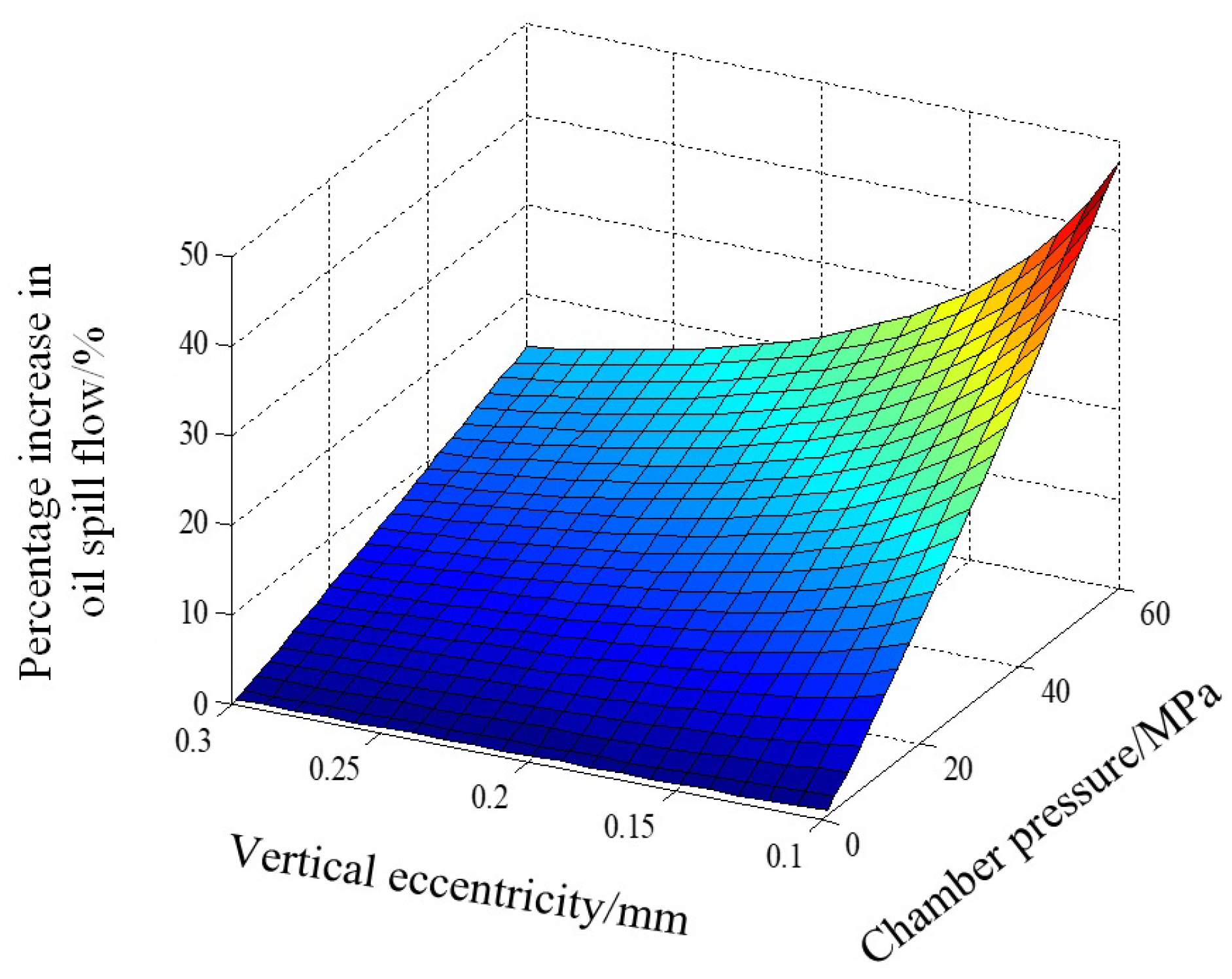
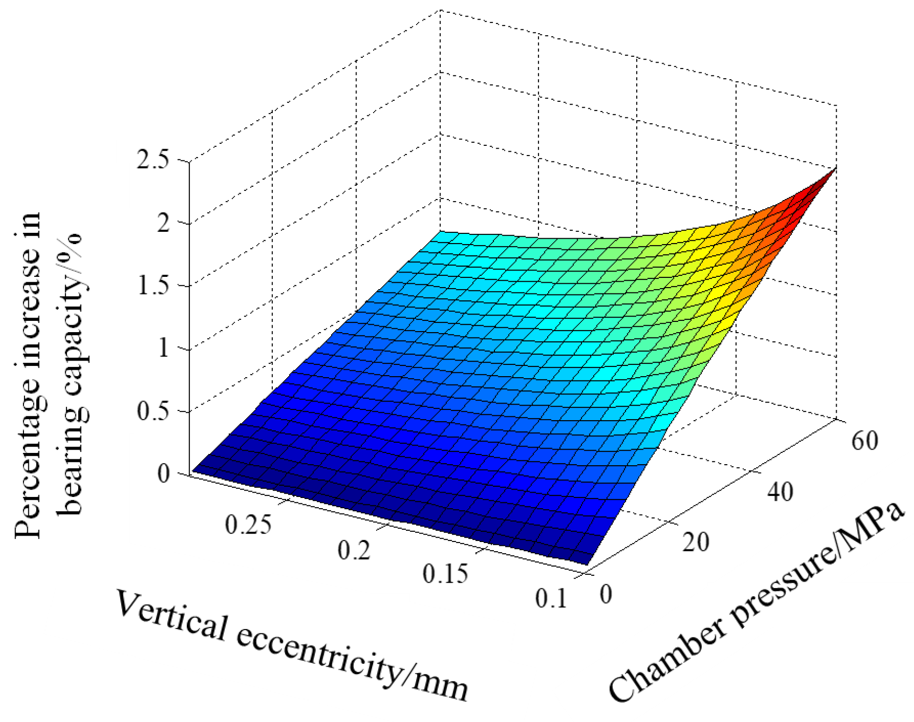
The control program incorporates the pressure of the high-pressure oil chamber and the vertical eccentricity as input variables to calculate the bearing characteristic parameters for various parameter combinations. The calculations include determining the increase in bearing capacity and the increase in oil spill flow. This study considers a vertical eccentricity range of 0.1 < e < 0.3 mm, 0.01 mm between two adjacent data, that is, e = 0.10, 0.11, 0.12, …, 0.29, 0.30 mm. There is a high-pressure oil chamber pressure range of 1 < p < 60 MPa, 2.5 MPa between two adjacent data, except for the first and second data points, that is, p = 1.0, 2.5, 5.0,…, 57.5, 60.0 MPa. The resulting increase in bearing capacity is depicted in Figure 10, while the increase in oil spill flow is illustrated in Figure 11.
The analysis of Figure 10 and Figure 11 reveals that the increase in bearing capacity is below 2.5%. The bearing capacity rises with increasing pressure, while it decreases with increasing vertical eccentricity. Notably, when the vertical eccentricity is small and the pressure is large, the bearing capacity experiences a rapid increase. The increase in oil spillage is approximately 50%, and it closely follows the patterns of vertical displacement and pressure. However, in cases where the vertical eccentricity is small and the pressure is large, the increase is more pronounced. This can be attributed to the smaller width of the oil gap at the sealing edge when the vertical eccentric distance is small. Additionally, the relationship between surface elastic deformation and pressure causes a greater pressure-induced deformation, resulting in a significant increase in the gap width at the oil seal edge and, consequently, a rapid growth in oil spill flow.
4. Conclusions
This study simplifies the physical model of the spherical hydrostatic bearing and deduces the differential equation for its bearing capacity using the Navier–Stokes equation. Numerical calculations are performed using an example, resulting in a relative error of 1.80% between the calculated value and the empirical value.
The findings highlight the significant impact of surface elastic deformation on the bearing parameters of the hydrostatic spherical bearing, particularly when there is a smaller vertical offset (resulting in a narrower edge seal gap) and a higher pressure in the high-pressure oil cavities. The influence of surface elastic deformation on liquid hydrostatic spherical bearings is mainly reflected in the influence on the oil spill flow. When the vertical eccentricity of the bearing body is small and the pressure of the high-pressure oil chamber is large, the calculated oil relief flow rate increases relatively rapidly. Considering the amount of surface elastic deformation, the bearing capacity of the hydrostatic spherical bearings experiences a slight increase, while the oil spill flow exhibits a rapid increase. Therefore, when calculating the bearing characteristic parameters of the hydrostatic bearing, it is essential to account for the influence of surface elastic deformation on the spherical hydrostatic bearing.
Author Contributions
Conceptualization, S.Z. and G.L. methodology, G.C. and Z.Z.; data curation, S.Z. and J.L.; Writing—original draft preparation, S.Z. and G.L.; writing—review and editing, S.Z., D.Y., Y.C. and G.L. All authors have read and agreed to the published version of the manuscript.
Funding
This research and APC were funded by the Shandong Province Higher Education Undergraduate Teaching Reform Research Project (No. Z2023085) and the “Hundred Outstanding Talents” of Jining University (No. 2023ZYRC56).
Data Availability Statement
Data are contained within the article.
Conflicts of Interest
Author D.Y. was employed by the company Shandong Xinneng Shipbuilding Co., Ltd. The other authors were conducted in the absence of any commercial or financial relationships that could be construed as a potential conflict of interest.
References
- Deng, H.; Hu, C.; Wang, Q.; Wang, L.; Wang, C. Friction and wear analysis of the external return spherical bearing pair of axial piston pump/motor. Mech. Ind. 2020, 21, 104. [Google Scholar] [CrossRef]
- Lin, S.C. Friction and Lubrication of sliding bearings. Lubricants 2023, 11, 226. [Google Scholar] [CrossRef]
- Li, J.; Yamada, S.; Kishiki, S.; Yamazaki, S.; Watanabe, A.; Terashima, M. Experimental and numerical study of spherical sliding bearing (SSB)-part 2: Friction models. In Proceedings of the 17th World Conference on Earthquake Engineering, 17WCEE, Sendai, Japan, 28 September–2 October 2021. [Google Scholar]
- Ryan, K.L.; Mojidra, R. Analysis of effect of vertical ground shaking in bridges isolated with spherical sliding bearings. Earthq. Eng. Struct. Dyn. 2023, 52, 5010–5032. [Google Scholar] [CrossRef]
- Deng, H.; Zhu, P.; Hu, C.; He, T. Study on dynamic lubrication characteristics of the external return spherical bearing pair under full working conditions. Machines 2022, 10, 107. [Google Scholar] [CrossRef]
- Tomar, A.K.; Sharma, S.C. Non-Newtonian lubrication of hybrid multi-recess spherical journal bearings with different geometric shapes of recess. Tribol. Int. 2022, 171, 107579. [Google Scholar] [CrossRef]
- Yang, Y.; Zhang, Y.; Ju, J. Study on the mechanical properties of a type of spherical bearing. J. Theor. Appl. Mech. 2021, 59, 539–550. [Google Scholar] [CrossRef]
- Meyer, D. Reynolds equation for spherical bearings. J. Tribol. 2003, 125, 203–206. [Google Scholar] [CrossRef]
- Elescandarany, A.W. Kugel ball nature: Hydrodynamics-mathematics-design. Appl. Eng. Sci 2002, 9, 100078. [Google Scholar] [CrossRef]
- Kazama, T. Design of hydrostatic spherical bearing’s in fluid film lubrication. J. Tribol. 2000, 1228, 66–69. [Google Scholar] [CrossRef]
- Yacout, A.W.; Ismail, A.S.; Kassab, S.Z. The combined effects of the centripetal inertia and the surface roughness on the hydrostatic thrust spherical bearings performance. Tribol. Int. 2007, 40, 522–532. [Google Scholar] [CrossRef]
- Elescandarany, A.W.Y. The effect of the fluid film variable viscosity on the hydrostatic thrust spherical bearing performance in the presence of centripetal inertia and surface roughness. Int. J. Mech. Eng. Appl. 2018, 6, 1–12. [Google Scholar] [CrossRef]
- Yacout, A.W.; Ismail, A.S.; Kassab, S.Z. The surface roughness effect on the hydrostatic thrust spherical bearings performance (part 2 un-recessed clearance type). In Proceedings of the ASME, International Mechanical Engineering Congress and Exposition, IMECE2006-13004, Chicago, IL, USA, 5–10 November 2006. [Google Scholar] [CrossRef]
- Yacout, A.W.; Ismail, A.S.; Kassab, S.Z. The surface roughness effect on the hydrostatic thrust spherical bearings performance (part 3 recessed clearance type of bearings). In Proceedings of the ASME International Mechanical Engineering Congress and Exposition, IMECE 2007-41013, Seattle, WA, USA, 11–15 November 2007. [Google Scholar] [CrossRef]
- Elescandarany, A.W. Externally pressurized thrust spherical bearing performance under variable lubricant viscosity (un-recessed clearance type). Int. J. Mech. Eng. Appl. 2020, 8, 45–64. [Google Scholar]
- Elescandarany, A.W.Y. Design of the hydrostatic thrust spherical bearing with restrictors (fitted type). Int. J. Mech. Eng. Appl. 2019, 7, 34–45. [Google Scholar]
- Elescandarany, A.W.Y. Design of self-restriction hydrostatic thrust spherical bearing (fitted type). Int. J. Mech. Eng. Appl. 2019, 7, 111–122. [Google Scholar]
- Elescandarany, A.W. Kugel ball as an interesting application of designing the hydrosphere. Int. J. Mech. Eng. Appl. 2021, 9, 25–32. [Google Scholar]
- Rajashekar, M.; Kashinath, B. Effect of surface roughness on MHD couple stress squeeze-film characteristics between a sphere and a porous plane surface. Adv. Tribol. 2012, 2012, 935690. [Google Scholar] [CrossRef]
- Rao, R.R.; Gowthami, K.; Kumar, J.V. Effects of velocity-slip and viscosity variation in squeeze film lubrication of spherical bearings. In Proceedings of ICATES; Springer: Delhi, India, 2013; pp. 35–47. [Google Scholar] [CrossRef]
- Tao, J.Z.; Yin, G.F.; Wang, F.Y. An optimism method of air static pressure ball bear parameters. China Mech. Eng. 2004, 15, 48–50. [Google Scholar] [CrossRef]
- Guo, X.P.; He, H.T.; Zhao, L. Optimization design of non-liquid friction spherical sliding bearing based on ANSYS. Bearing. 2007, 2, 4–5. [Google Scholar] [CrossRef]
- Luo, L.; Wang, X. Finite element analysis of self-Lubricating joint bearing liner wear. In Proceedings of the 2017 International Conference on Computer Technology, Electronics and Communication (ICCTEC), Dalian, China, 19–21 December 2017; pp. 245–249. [Google Scholar] [CrossRef]
- Luo, L.; Wang, X.; Liu, H.; Zhu, L. Number simulation analysis of self-lubricating joint bearing liner wear. Int. J. Interact. Des. Manuf. 2019, 13, 23–34. [Google Scholar] [CrossRef]
- Royston, T.J.; Basdogan, I. Vibration transmission through self-aligning (spherical) rolling element bearings: Theory and experiment. J. Sound Vib. 1998, 215, 997–1014. [Google Scholar] [CrossRef]
- Geng, K.; Lin, S. Effect of angular misalignment on the stiffness of the double-row self-aligning ball bearing. Proc. Inst. Mech. Eng. Part C J. Mech. Eng. Sci. 2020, 234, 946–962. [Google Scholar] [CrossRef]
- Ambrożkiewicz, B.; Syta, A.; Gassner, A.; Georgiadis, A.; Litak, G.; Meier, N. The influence of the radial internal clearance on the dynamic response of self-aligning ball bearings. Mech. Syst. Signal Process. 2022, 171, 108954. [Google Scholar] [CrossRef]
- Zhuo, Y.; Zhou, X.; Yang, C. Dynamic analysis of double-row self-aligning ball bearings due to applied loads, internal clearance, surface waviness and number of balls. J. Sound Vib. 2014, 333, 6170–6189. [Google Scholar] [CrossRef]
- Parmar, V.; Saran, V.H.; Harsha, S.P. Effect of an unbalanced rotor on dynamic characteristics of double-row self-aligning ball bearing. Eur. J. Mech. A/Solids 2020, 82, 104006. [Google Scholar] [CrossRef]
- Parmar, V.; Saran, V.H.; Harsha, S.P. Nonlinear vibration response analysis of a double-row self-aligning ball bearing due to surface imperfections. Proc. Inst. Mech. Eng. Part K J. Multi-Body Dyn. 2020, 234, 514–535. [Google Scholar] [CrossRef]
- Liu, Z.L.; Lu, J.; Zhou, J.N. The research on the design of largescale static pressure spherical bearing used in propeller balancing installation. J. Wuhan Univ. Technol. (Transp. Sci. Eng.) 2003, 27, 429–432. [Google Scholar]
- Liu, Z.L.; Xiao, H.L.; Zhou, J.N. Design of large-sized static pressure ball bearing. Ship Eng. 1999, 05, 25–27. [Google Scholar]
- Wang, C.T.; Wu, U.J.; Chen, L. Algorithm improvement and experimental research for propeller static balancing detection. Sci. Technol. Eng. 2015, 15, 294–297. [Google Scholar]
- Qian, L.B.; Jiang, Y.H. Design of mechanical prop based on space and tracks movement. Equip. Manuf. Technol. 2012, 03, 8–9. [Google Scholar]
- Li, Y.L.; Guo, W.; Wu, S.S. R & T on high precision static balancing machine of propeller hanging type for large marine. Mach. Des. Manuf. 2011, 59–61. [Google Scholar] [CrossRef]
- Huang, W.X.; Li, J.M.; Xiao, Z.Y. Engineering Fluid Mechanics; Chemical Industry Press: Beijing, China, 2009. [Google Scholar]
- Xu, X.L.; Deng, H.S.; Wang, C.L. Theory study of spherical interstitial flow. Chin. Hydraul. Pneum. 2004, 10, 3–5. [Google Scholar]
- Ouyang, W.; Liu, Q.; Xiao, J.; Huang, J.; Zhang, Z.; Wang, L. Experimental study on the distributed lubrication characteristics of full-size water-lubricated stern bearings under hull deformation. Ocean Eng. 2023, 267, 113226. [Google Scholar] [CrossRef]
- Tieu, A.K.; Freund, N.O. A high performance journal bearing with controlled elastic deflection. J. Tribol. 1995, 117, 702. [Google Scholar] [CrossRef]
- Sun, Y.H.; Ma, X.Z. Influence of elastic deformation on ball mill bearing. Lubr. Eng. 2011, 36, 65–69. [Google Scholar]
- Duan, F.L.; Wei, Y.L. Effect of elastic deformation on the lubrication performance of journal bearing. Lubr. Eng. 2000, 06, 9–10. [Google Scholar]
Figure 1.
The structure of hydrostatic spherical bearing. 1—the body of the spherical bearing; 2—the gap of the oil spill; 3—spherical bearing housing; 4—high-pressure oil cavity; 5—oil supply hole.
Figure 1.
The structure of hydrostatic spherical bearing. 1—the body of the spherical bearing; 2—the gap of the oil spill; 3—spherical bearing housing; 4—high-pressure oil cavity; 5—oil supply hole.
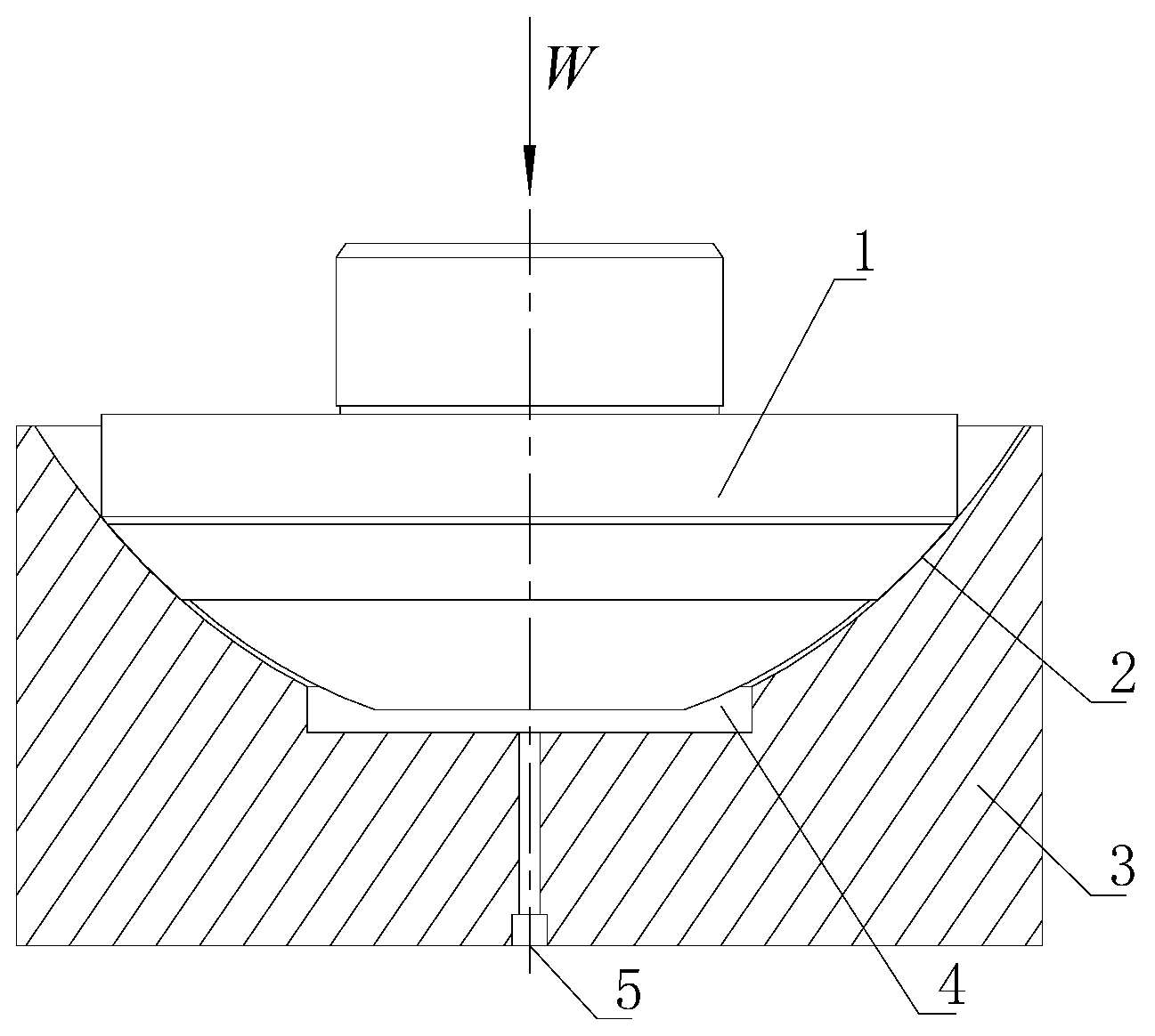
Figure 2.
The simplified model of spherical bearing oil-sealing edge.
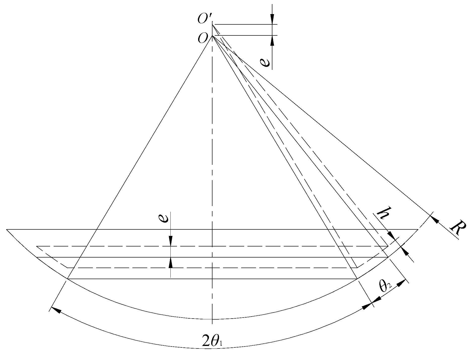
Figure 3.
Slit schematic diagram of spherical eccentricity.
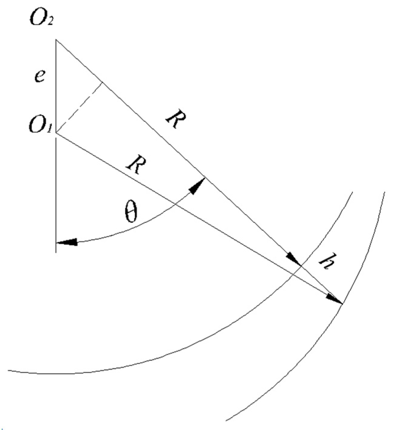
Figure 4.
Discrete model of spherical bearing and parameter definition.
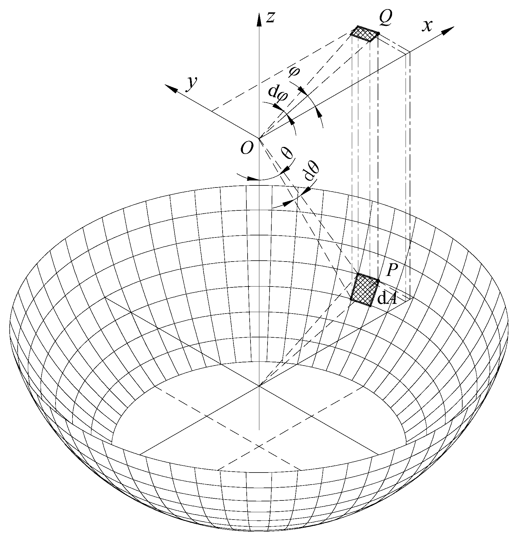
Figure 5.
Numerical solution flowchart of differential fluid flow equation of oil-sealing edge.
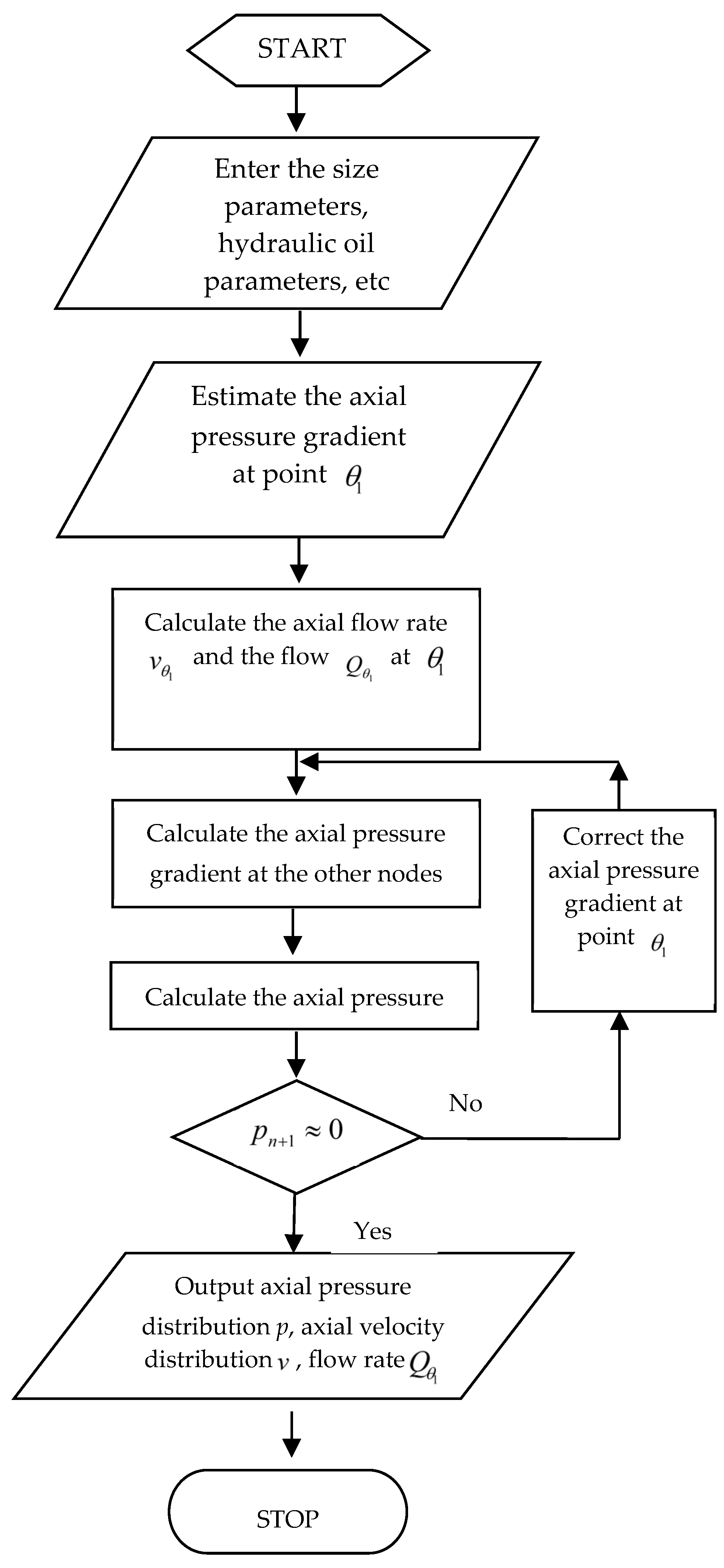
Figure 6.
Convergence curve of outlet pressure.
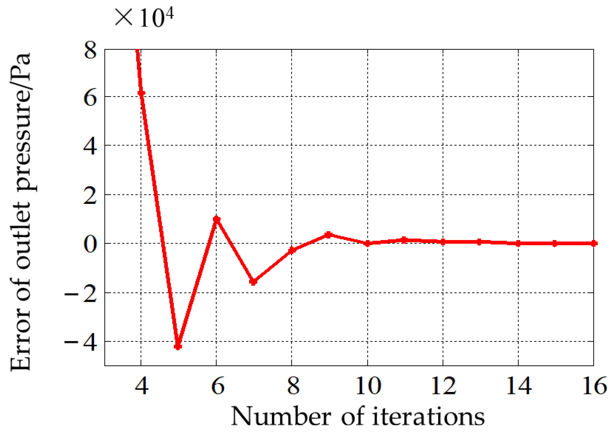
Figure 7.
Shape schematic diagram of half-space body.
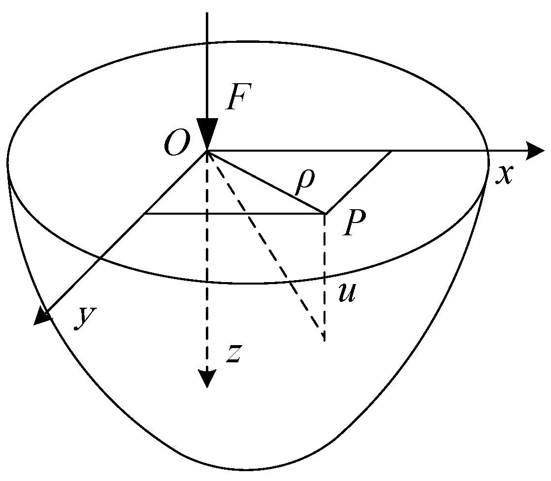
Figure 8.
Convergence curve errors of the surface of the elastic deformation.
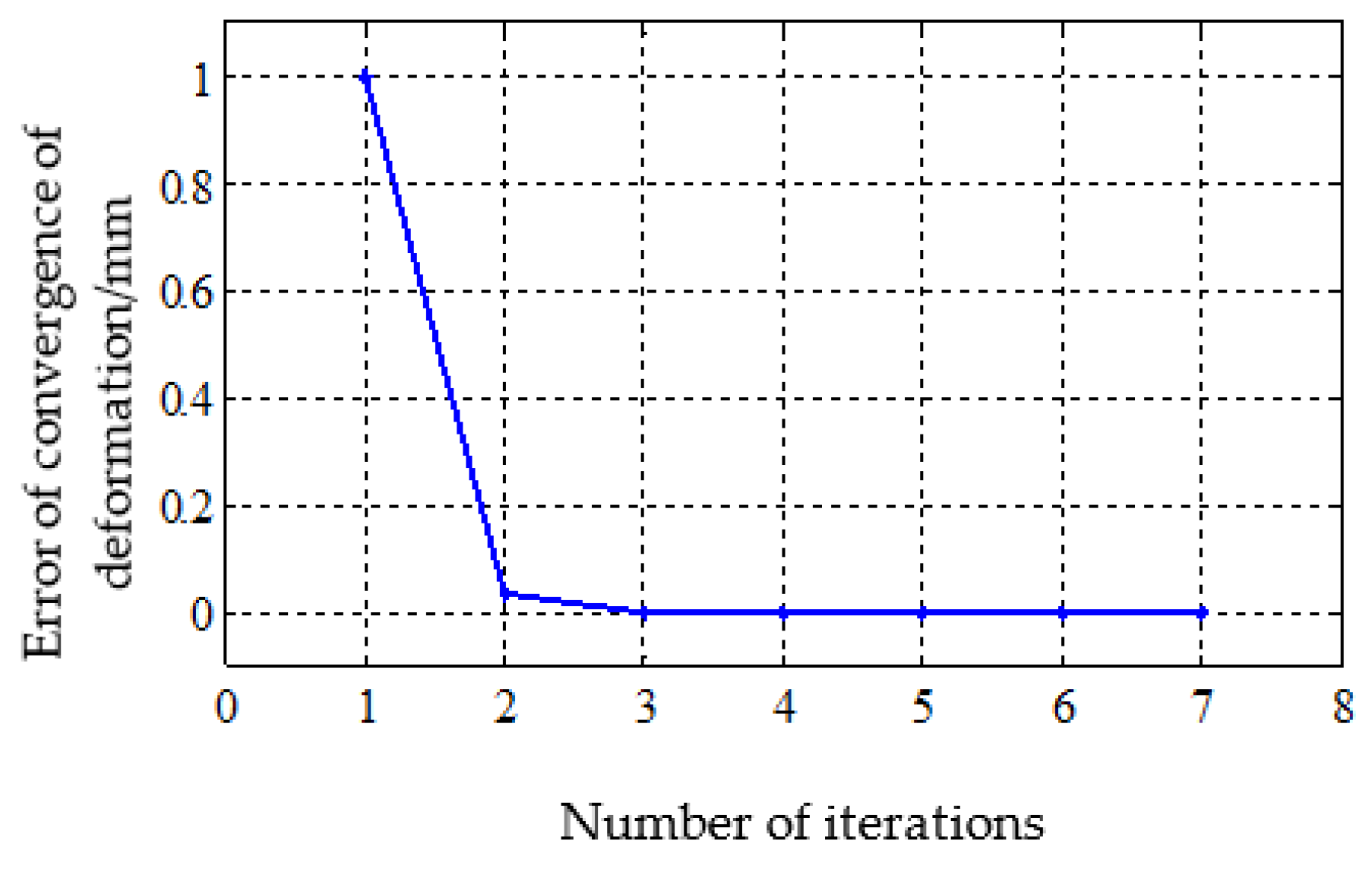
Figure 9.
The curve of sealing edge crack width.
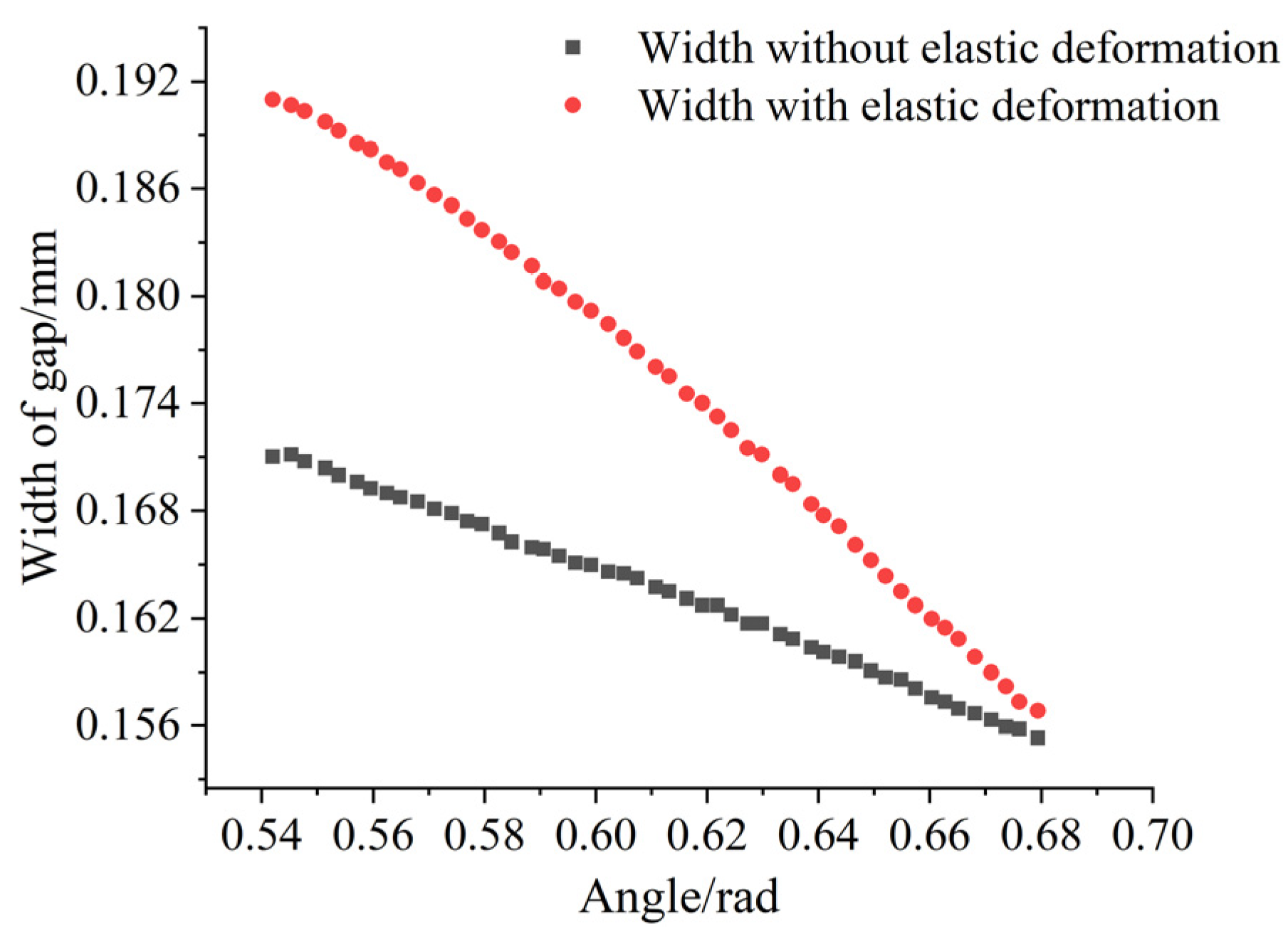
Figure 10.
Percentage increase in carrying capacity under different vertical eccentricities and chamber pressures.
Figure 10.
Percentage increase in carrying capacity under different vertical eccentricities and chamber pressures.

Figure 11.
Percentage increase in oil spill flow at different vertical eccentricities and chamber pressures.
Figure 11.
Percentage increase in oil spill flow at different vertical eccentricities and chamber pressures.

Table 1.
Basic design parameters of spherical hydrostatic bearings.
| Cases | Symbol | Unit | Value |
|---|---|---|---|
| Spherical radius | R | mm | 350 |
| The angle of a high-pressure oil chamber | (°) | 62.0 | |
| The angle of the unilateral oil seal side | (°) | 8.00 | |
| Average oil film thickness | h | mm | 0.20 |
| Max speed of circumference | 200 | ||
| The pressure of a high-pressure oil chamber | MPa | 4.00 | |
| Viscosity of hydraulic oil | Pa·s | 0.0495 | |
| Density of hydraulic oil | 900 |
Table 2.
Material parameters of spherical bearing components.
| Components | Material | Density /(kg·m−3) | Elastic Modulus E/GPa | Poisson’s Ratio |
|---|---|---|---|---|
| Bearing body | Bronze | 8300 | 110 | 0.37 |
| Bearing housings | Cast steel | 7800 | 210 | 0.31 |
Table 3.
The limit values of the surface of elastic deformation (mm).
| Components | The Maximum Amount of Elastic Deformation | The Minimum Amount of Elastic Deformation |
|---|---|---|
| Bearing body | 1.284 × 10⁻² | 9.610 × 10⁻⁴ |
| Bearing housings | 7.05 × 10⁻³ | 5.27 × 10⁻⁴ |
Table 4.
The influence of surface of elastic deformation on loading characteristics.
| Parameters | With Elastic Deformation | Without Elastic Deformation | Increase Rate/% |
|---|---|---|---|
| Bearing capacity of sealing the oil side F2/kN | 1623 | 1539 | 5.45 |
| Total bearing capacity F/kN | 7874 | 7790 | 1.07 |
| Flow of oil spill Q/(L·min−1) | 290.2 | 238.4 | 21.74 |
| Average speed of output vavg/(m·s−1) | 22.28 | 18.47 | 20.62 |
| Frictional moment of rotational resistance M/(N·m) | 7.49 | 7.97 | −6.03 |
Disclaimer/Publisher’s Note: The statements, opinions and data contained in all publications are solely those of the individual author(s) and contributor(s) and not of MDPI and/or the editor(s). MDPI and/or the editor(s) disclaim responsibility for any injury to people or property resulting from any ideas, methods, instructions or products referred to in the content. |
© 2024 by the authors. Licensee MDPI, Basel, Switzerland. This article is an open access article distributed under the terms and conditions of the Creative Commons Attribution (CC BY) license (https://creativecommons.org/licenses/by/4.0/).
Share and Cite
MDPI and ACS Style
Zhang, S.; Yang, D.; Li, G.; Cheng, Y.; Chen, G.; Zhang, Z.; Li, J. Carrying Capacity of Spherical Hydrostatic Bearings including Elastic Deformation. Lubricants 2024, 12, 97. https://doi.org/10.3390/lubricants12030097
AMA Style
Zhang S, Yang D, Li G, Cheng Y, Chen G, Zhang Z, Li J. Carrying Capacity of Spherical Hydrostatic Bearings including Elastic Deformation. Lubricants. 2024; 12(3):97. https://doi.org/10.3390/lubricants12030097
Chicago/Turabian StyleZhang, Shengdong, Dongjiang Yang, Guangming Li, Yongchao Cheng, Guang Chen, Zhiming Zhang, and Jichao Li. 2024. "Carrying Capacity of Spherical Hydrostatic Bearings including Elastic Deformation" Lubricants 12, no. 3: 97. https://doi.org/10.3390/lubricants12030097
Note that from the first issue of 2016, this journal uses article numbers instead of page numbers. See further details here.