
The Influence of Tool Texture on Friction and Lubrication in Strip Reduction Testing


Abstract
:
1. Introduction
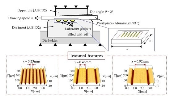
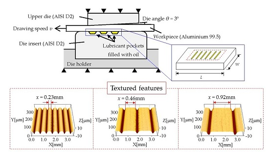
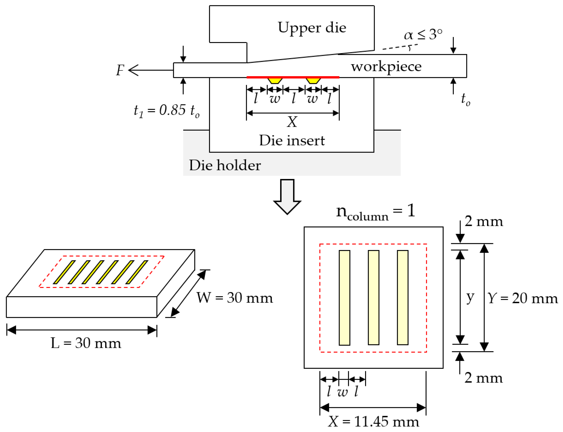
2. Test Setup
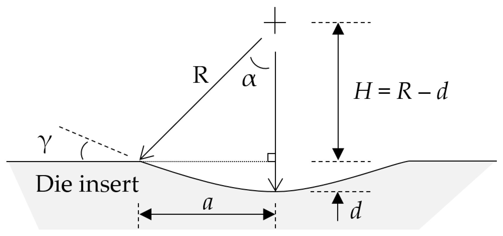
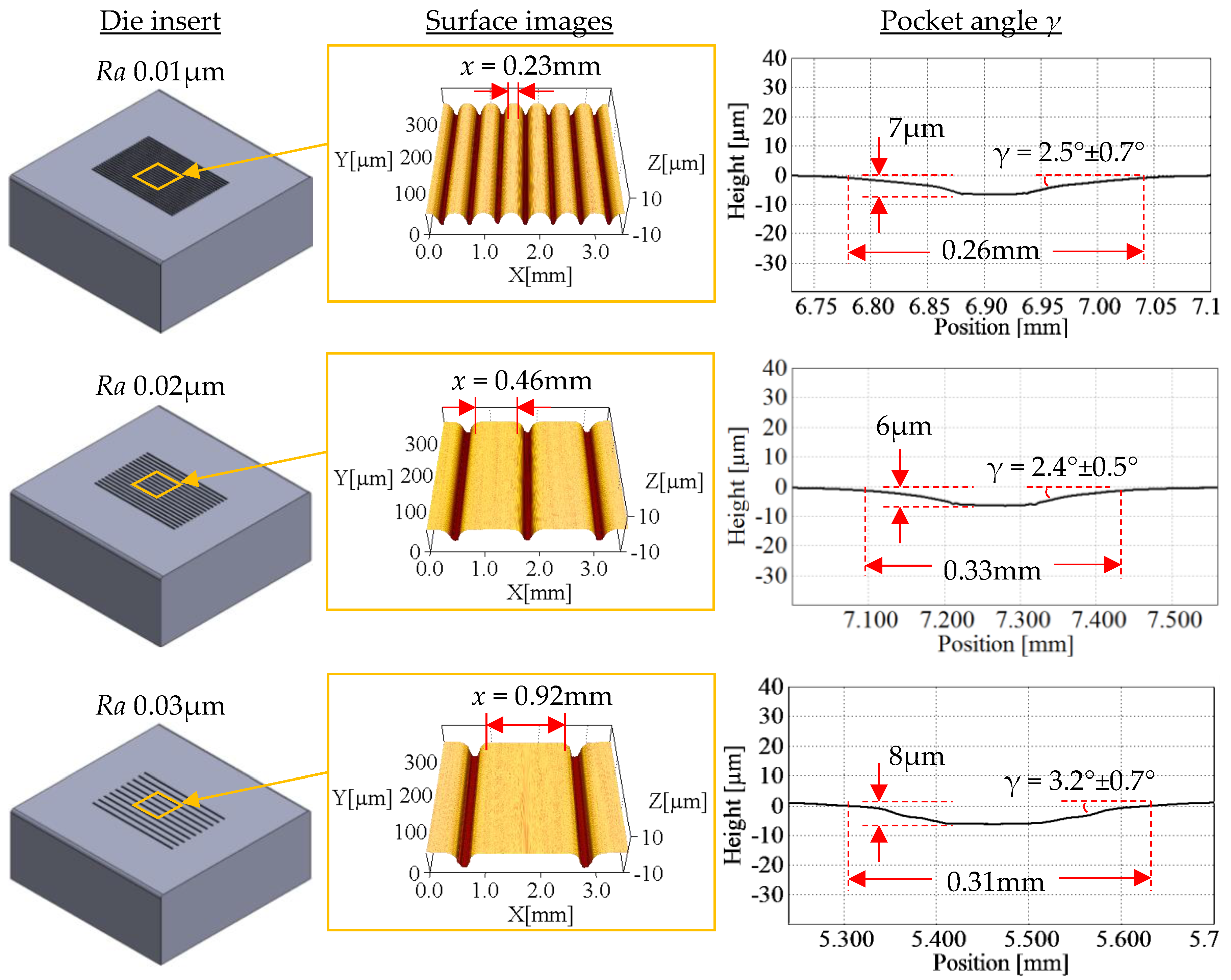
3. Manufacture of Surface Textures
4. Test Materials
4.1. Tool Material
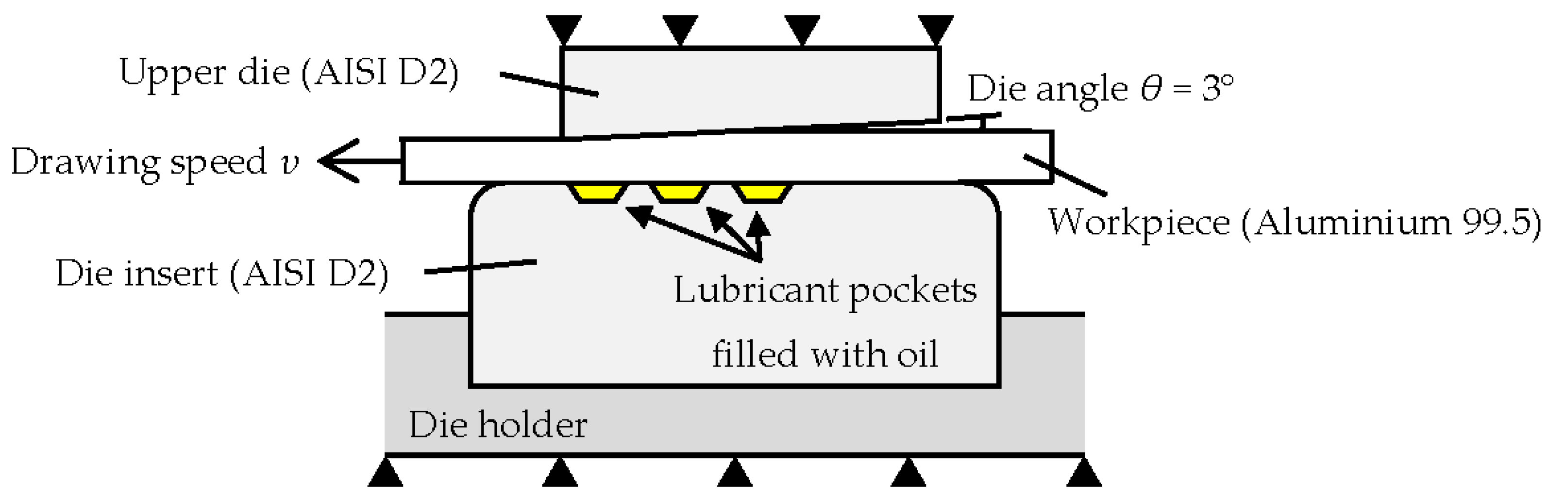
4.2. Workpiece Material
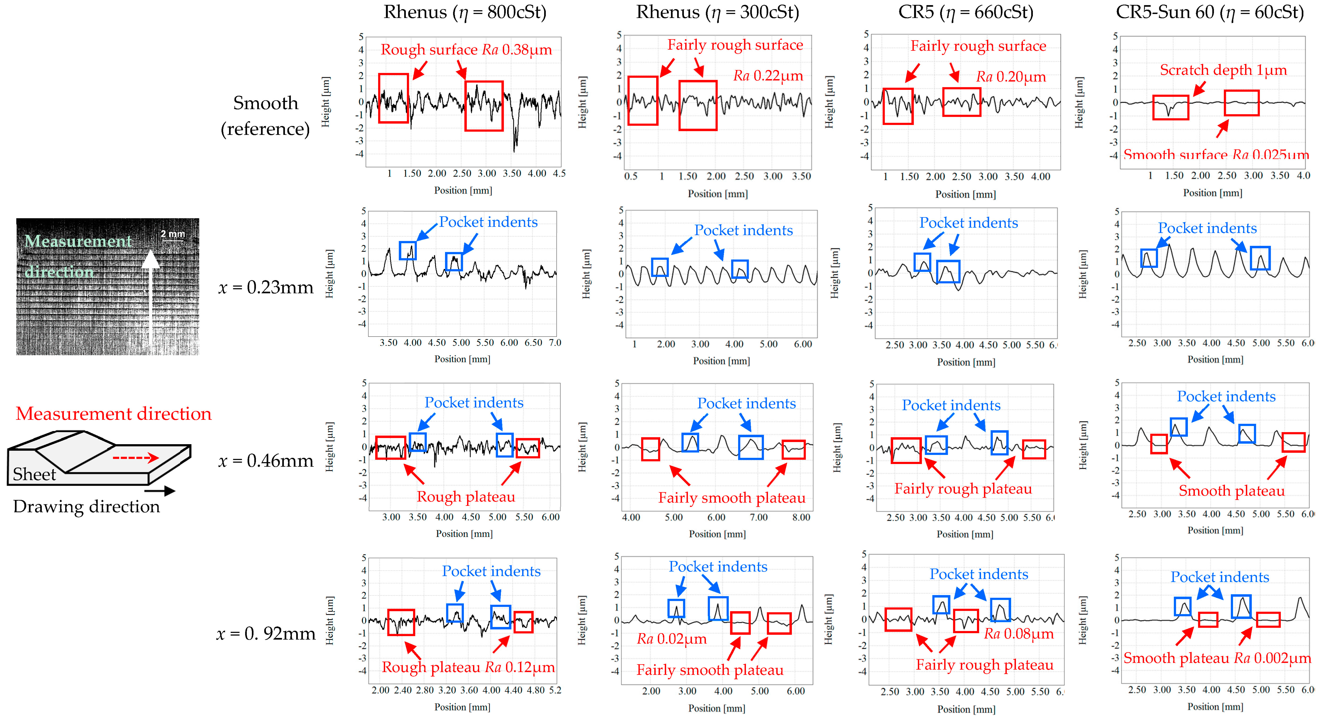
4.3. Lubricants
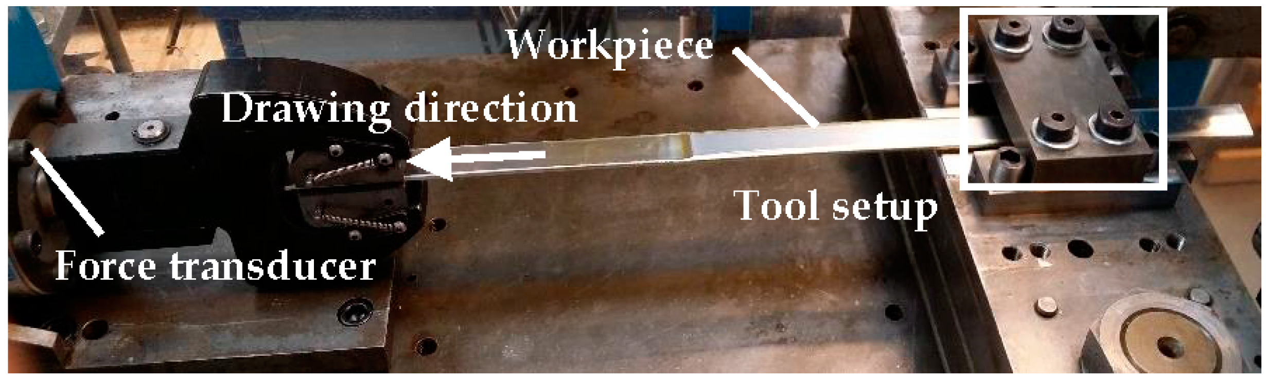
5. Test Procedure
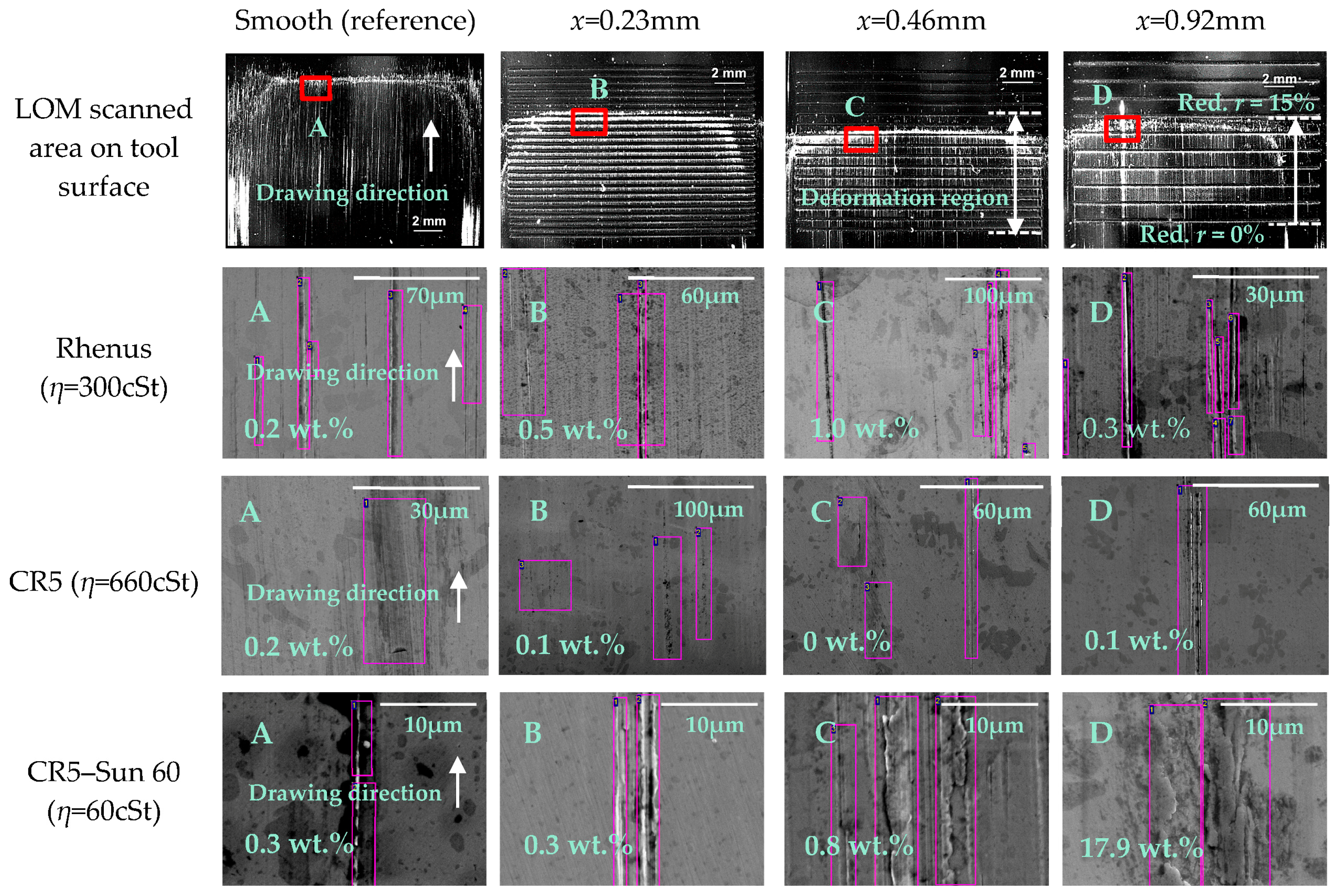
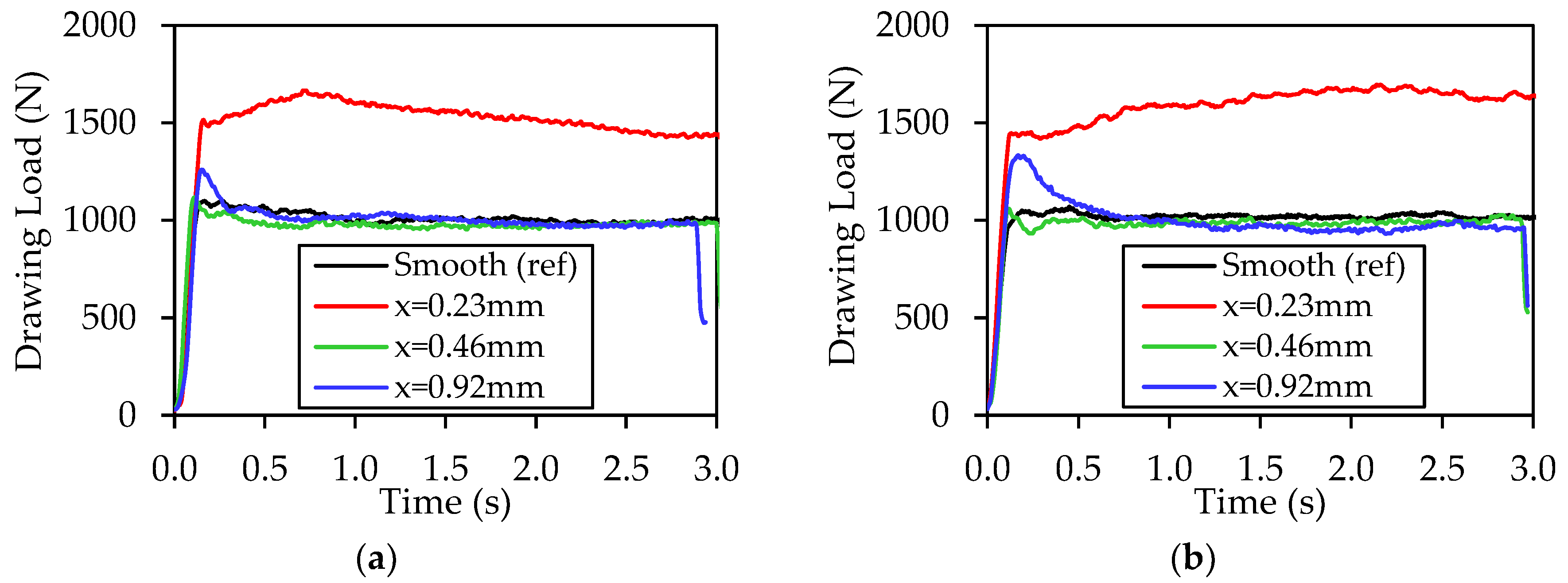
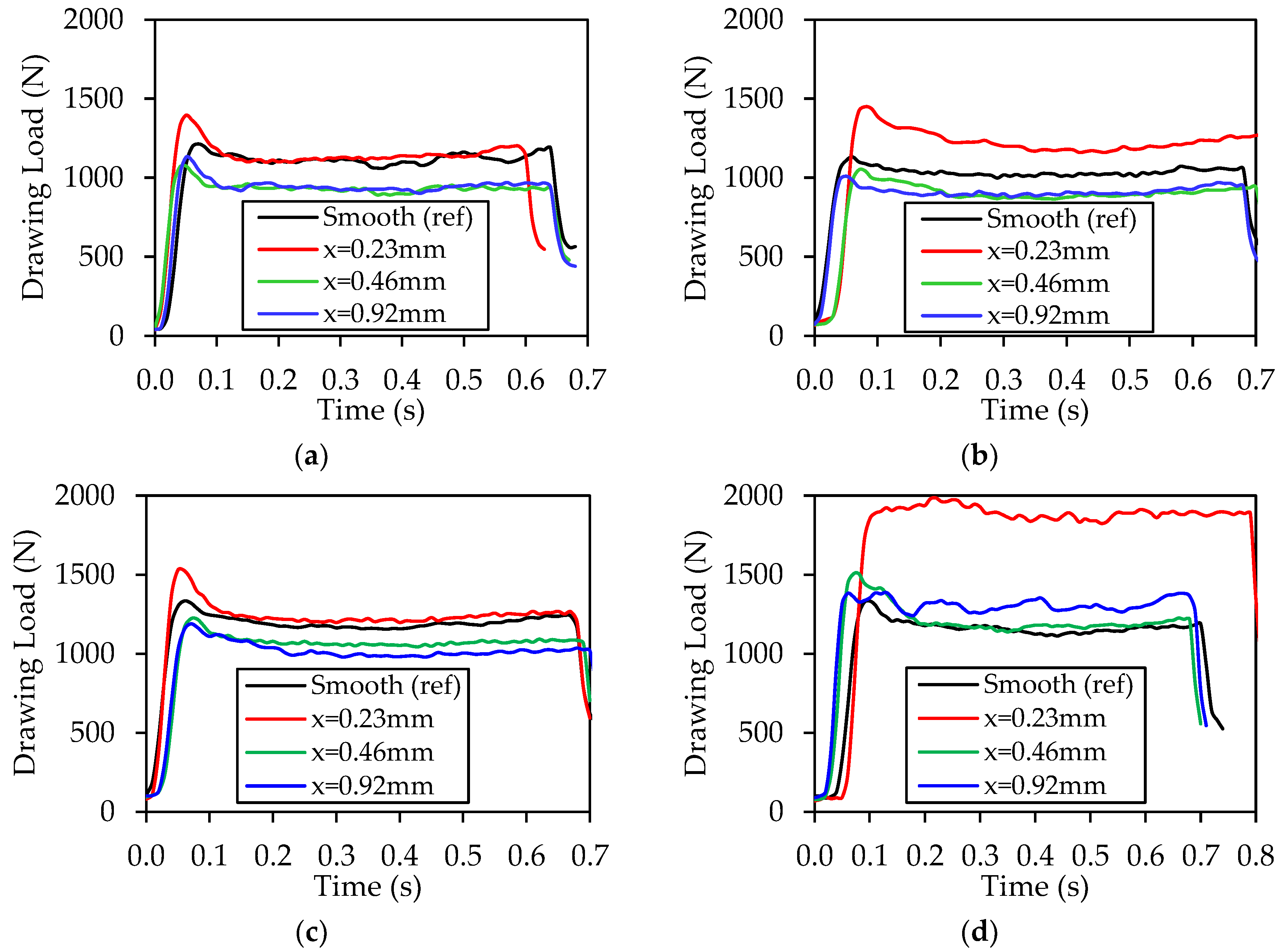
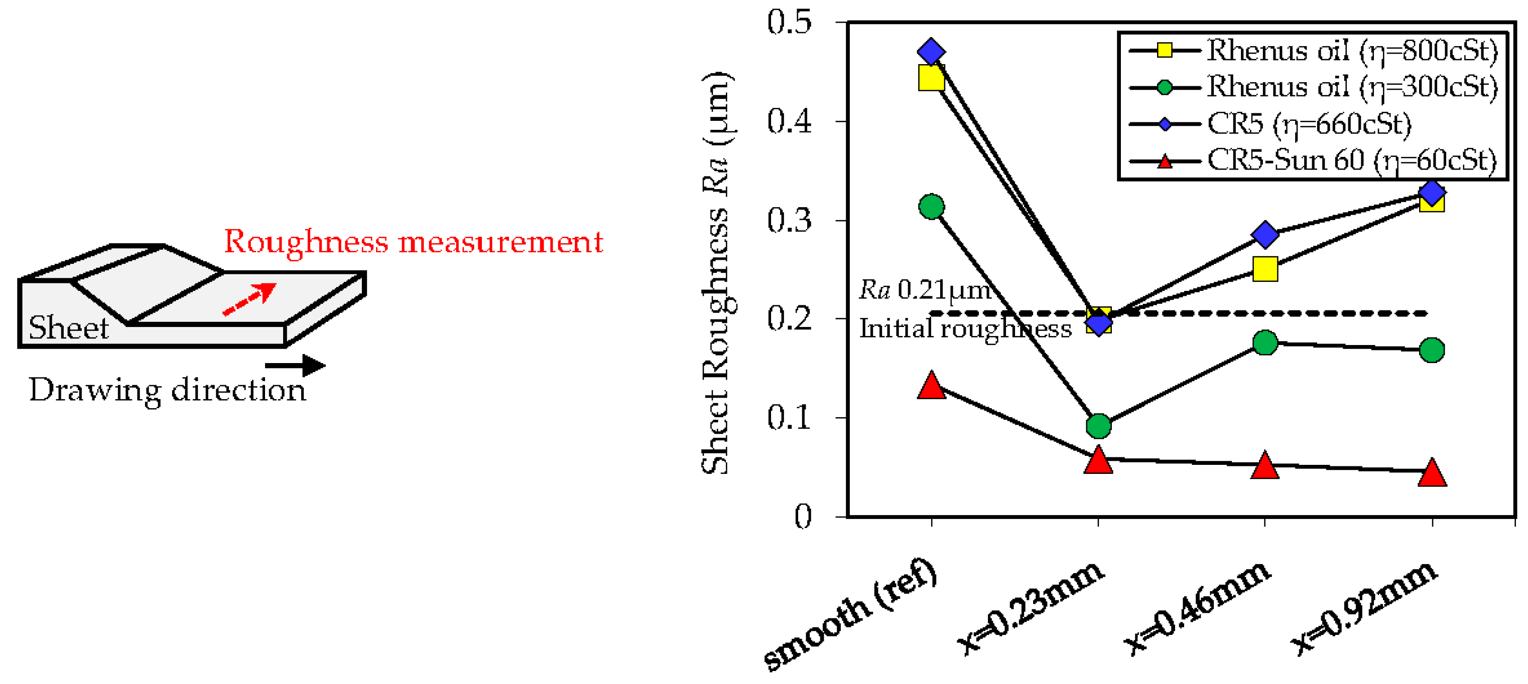
6. Results and Discussion
7. Conclusions
Acknowledgments
Author Contributions
Conflicts of Interest
References
- Ibatan, T.; Uddin, M.S.; Chowdhury, M.A.K. Recent development on surface texturing in enhancing tribological performance of bearing sliders. Surf. Coat. Technol. 2015, 272, 102–120. [Google Scholar] [CrossRef]
- Vladescu, S.C.; Olver, A.V.; Pegg, I.G.; Reddyhoff, T. The effects of surface texture in reciprocating contacts—An experimental study. Tribol. Int. 2015, 82, 28–42. [Google Scholar] [CrossRef]
- Bruzzone, A.A.G.; Costa, H.L.; Lonardo, P.M.; Lucca, D.A. Advances in engineered surfaces for functional performance. CIRP Ann. Manuf. Technol. 2008, 57, 750–769. [Google Scholar] [CrossRef]
- Geiger, M.; Engel, U.; Pfestorp, M. New developments for the qualification of technical surfaces in forming processes. Ann. CIRP 1997, 46, 171–174. [Google Scholar] [CrossRef]
- Schmoeckel, D.; Prier, M.; Staeves, J. Topography deformation of sheet metal during the forming process and its influence on friction. Ann. CIRP 1997, 46, 175–178. [Google Scholar] [CrossRef]
- Kudo, H.; Azushima, A. Direct observation of contact behaviour to interpret the pressure dependence of the coefficient of friction in sheet metal forming. Ann. CIRP 1995, 1, 209–212. [Google Scholar]
- Bay, N.; Bech, J.I.; Andreasen, J.L.; Shimizu, I. Studies on micro plasto hydrodynamic lubrication in metal forming. In Metal Forming Science and Practice: A State-of-the-Art Volume in Honour of Professor J.A. Schey's 80th Birthday, 1st ed.; Lenard, J.G., Ed.; Elsevier Science Ltd.: Oxford, United Kingdom, 2002; Chapter 7; pp. 115–134. [Google Scholar]
- Kijima, H.; Bay, N. Contact conditions in skin-pass rolling. Ann. CIRP 2007, 1, 301–306. [Google Scholar] [CrossRef]
- Groche, P.; Stahlmann, J.; Hartel, J.; Kohler, M. Hydrodynamic effects of macroscopic deterministic surface structures in cold forging processes. Tribol. Int. 2009, 42, 1173–1179. [Google Scholar] [CrossRef]
- Lindvall, F.; Bergstrom, J.; Krakhmalev, P.; Bay, N. The effect of grinding and polishing procedure of tool steels in sheet metal forming. In Proceedings of the 4th International Conference on Tribology in Manufacturing Processes, (ICTMP 2010), Nice, France, 13–15 June 2010; Felder, E., Montmitonnet, P., Eds.; Presses des MINES: Paris, France, 2010; Volume 2, pp. 603–612. [Google Scholar]
- Wiklund, D.; Liljebgren, M.; Berglund, J.; Bay, N.; Kjellsson, K.; Rosen, B.-G. Friction in sheet metal forming—A comparison between machined and manually polished die surfaces. In Proceedings of the 4th International Conference on Tribology in Manufacturing Processes, (ICTMP 2010), Nice, France, 13–15 June 2010; Felder, E., Montmitonnet, P., Eds.; Presses des MINES: Paris, France, 2010; Volume 2, pp. 613–622. [Google Scholar]
- Eriksen, R.S.; Arentoft, M.; Gronbak, J.; Bay, N. Manufacture of functional surfaces through combined application of tool manufacturing processes and Robot Assisted Polishing. CIRP Ann. Manuf. Technol. 2012, 61, 563–566. [Google Scholar] [CrossRef] [Green Version]
- Godi, A.; Gronbak, J.; De Chiffre, L. Off-line testing of multifunctional surfaces for metal forming applications. CIRP J. Manuf. Sci. Technol. 2015, 11, 28–35. [Google Scholar] [CrossRef] [Green Version]
- Popp, U.; Engel, U. Microtexturing of cold-forging tools—Influence on tool life. Proc. Inst. Mech. Eng. B 2006, 220, 27–33. [Google Scholar] [CrossRef]
- Costa, H.L.; Hutchings, I.M. Effects of die surface patterning on lubrication in strip drawing. J. Mater. Process. Technol. 2009, 209, 1175–1180. [Google Scholar] [CrossRef]
- Krux, R.; Homberg, W.; Kalveram, M.; Trompeter, M.; Kleiner, M.; Weinert, K. Die surface structures and hydrostatic pressure system for the material flow control in high-pressure sheet metal forming. Adv. Mater. Res. 2005, 6–8, 385–392. [Google Scholar] [CrossRef]
- Franzen, V.; Witulski, J.; Brosius, A.; Trompeter, M.; Tekkaya, A.E. Textured surfaces for deep drawing tools by rolling. Int. J. Mach. Tools Manuf. 2010, 50, 969–976. [Google Scholar] [CrossRef]
- Wagner, K.; Volkl, R.; Engel, U. Tool life enhancement in cold forging by locally optimized surfaces. J. Mater. Process. Technol. 2008, 201, 2–8. [Google Scholar] [CrossRef]
- Podgornik, B.; Jerina, J. Surface topography effect on galling resistance of coated and uncoated tool steel. Surf. Coat. Technol. 2012, 206, 2792–2800. [Google Scholar] [CrossRef]
- Shimizu, I.; Martins, P.A.F.; Bay, N.; Andreasen, J.L.; Bech, J.I. Influences of lubricant pocket geometry and working conditions upon micro lubrication mechanisms in upsetting and strip drawing. Int. J. Surf. Sci. Eng. 2010, 4, 42–54. [Google Scholar] [CrossRef]
- Bech, J.; Bay, N.; Eriksen, M. A study of mechanisms of liquid lubrication in metal forming. Ann. CIRP 1998, 47, 221–226. [Google Scholar] [CrossRef]
- Bech, J.I.; Bay, N.; Eriksen, M. Entrapment and escape of liquid lubricant in metal forming. Wear 1999, 232, 134–139. [Google Scholar] [CrossRef]
- Stachowiak, G.W.; Batchelor, A.W. Engineering Tribology, 3rd ed.; Butterworth-Heinemann Elsevier: Oxford, UK, 2014; pp. 1–852. [Google Scholar]


| Parameters | Value | ||
|---|---|---|---|
| Pocket angle γ (°) | 5 | ||
| Pocket width w = 2a (mm) | 0.23 | ||
| Pocket depth d (mm) | 0.01 | ||
| Pocket ratio d/w | 0.05 | ||
| Distance between pockets l (mm) | 1 × w | 2 × w | 4 × w |
| Number of pockets—row nrow | 25 | 16 | 10 |
| Number of pockets—column ncolumn | 1 | 1 | 1 |
| Initial pocket volume V0 (mm3) | 0.61 | 0.39 | 0.24 |
| Contact area ratio (Ar0/A0) (%) | 60 | 74 | 84 |
| Oil Type | Product Name | Kinematic Viscosity η [cSt @ 40 °C] |
|---|---|---|
| Mineral oil with additives | Rhenus LA 722086 1 | 800 |
| Mineral oil with additives | Rhenus LA 722083 1 | 300 |
| Pure mineral oil | CR5 Houghton Plunger 2 | 660 |
| Pure mineral oil | CR5–Sun 60 3 | 60 |
© 2017 by the authors. Licensee MDPI, Basel, Switzerland. This article is an open access article distributed under the terms and conditions of the Creative Commons Attribution (CC BY) license ( http://creativecommons.org/licenses/by/4.0/).
Share and Cite
Sulaiman, M.H.; Christiansen, P.; Bay, N. The Influence of Tool Texture on Friction and Lubrication in Strip Reduction Testing. Lubricants 2017, 5, 3. https://doi.org/10.3390/lubricants5010003
Sulaiman MH, Christiansen P, Bay N. The Influence of Tool Texture on Friction and Lubrication in Strip Reduction Testing. Lubricants. 2017; 5(1):3. https://doi.org/10.3390/lubricants5010003
Chicago/Turabian StyleSulaiman, Mohd Hafis, Peter Christiansen, and Niels Bay. 2017. "The Influence of Tool Texture on Friction and Lubrication in Strip Reduction Testing" Lubricants 5, no. 1: 3. https://doi.org/10.3390/lubricants5010003