Article

Tribocorrosion of Fe-Based Amorphous Coating in Simulated Body Fluids

College of Mechanical & Electrical Engineering, Hohai University, Changzhou 213022, China
*
Author to whom correspondence should be addressed.
Lubricants 2018, 6(2), 37; https://doi.org/10.3390/lubricants6020037
Submission received: 19 March 2018 / Revised: 9 April 2018 / Accepted: 12 April 2018 / Published: 18 April 2018
(This article belongs to the Special Issue Tribocorrosion of Surface Engineered Materials)

Abstract

:
An arc-sprayed Fe-based amorphous coating with high hardness and low porosity was prepared. A tribo-electrochemical approach was used to study the tribocorrosion behaviour of the amorphous coating. The volume wear losses of the amorphous coating with different sliding paths in dry, 0.9% NaCl, and PBS solutions were measured, as well as the friction coefficient and the polarization curves in static and dynamic situations. The volume wear loss with the linear sliding path is higher than those with circular and triangle paths. Since the ions in the solution accelerate the wear, the volume loss of the amorphous coating in 0.9% NaCl solution is higher than dry and in PBS solution. The wear loss of 316L stainless steel (SS) is about 1.7 times more than the amorphous coating in PBS solution under a load of 10 N. Although 316L SS possesses better corrosion resistance than the amorphous coating in the static situation, the corrosion resistance of the amorphous coating is much better than that of 316L SS during tribocorrosion. The wear mechanism of the amorphous coating includes abrasive wear accompanying with corrosive wear. For the intrinsic superior corrosion resistance, amorphous coating shows the prospective tribology application in the corrosion environment.

Graphical Abstract

1. Introduction

Metal biomaterials include pure titanium, titanium alloy, stainless steel, magnesium alloy, and so on [1,2]. Biomaterials are subjected to not only friction, but also corrosion. Therefore, biomaterials should possess excellent resistance of tribocorrosion. Amorphous alloy, also known as metallic glass, has a unique atomic arrangement with short range order and chemical homogeneity, which results in its excellent physical, chemical, and mechanical properties [3]. Johnson predicted that bulk amorphous alloy would become an important new engineering material in the twenty-first century [4]. In 1995, an Fe-based amorphous alloy was synthesized [5] and attracted great attentions, and Fe-based bulk metallic glass has better corrosion resistance than 316L stainless steel in simulated body fluids [6]. However, the application of bulk amorphous alloy is limited due to the small size.
Due to the excellent corrosion and friction resistance, high hardness, and no limitation of preparation, amorphous coating may behave well in body fluids. Recently, many alloy powders and cored wires are developed and widely used for amorphous coatings in arc spraying, plasma spraying, and so on [7,8]. Many amorphous coatings with excellent properties have been prepared by thermal spraying. The tribocorrosion resistance of electrodeposited Ni–W–P coating was investigated using a block-on-ring tester [9]. The wear resistance of the amorphous coating is about 4.6 times higher than that of 3Cr13 coating under the same testing conditions [10]. Our former work on the tribocorrosion resistance of CuZr-based amorphous forming alloys was also performed by a pin-on-disc tribometer [11]. Most of the wear testing machines related to the tribology of amorphous coatings use discs, and the corresponding friction depends on the rotation of the disk. Some other scholars also used linear reciprocating module to carry out the friction studies [1,12]. Meanwhile, the effect of the shapes of wear paths at the hip joint on the wear rates in a simulator was generated by Bennett et al., and the wear resistance of Fe-based amorphous coating at different sliding paths was investigated by using a sliding wear test machine [13].
In this work, an Fe-based amorphous coating was prepared by arc spraying, and the tribocorrosion behaviour of this amorphous coating was investigated, as well as the effect of sliding paths.

2. Materials and Method

2.1. Materials

The FeCrBNi amorphous coating was prepared on the Q345 low-alloy steel substrate by a ZPG-400B type (Shanghai Xinye Spray Machinery Co., Ltd., Shanghai, China) push and pull dual-purpose arc spraying machine. We used the step motor to control the speed of arc spraying and the distance between the surface of the steel and the nozzle of the arc spraying machine. The coating was fabricated with aspraying voltage of 34.2 V, the wire feed rate was 30 mm s−1, and the stand-off distance was 100 mm. Before spraying, the surface of the steel substrate was treated by sand blasting, alkali and water cleaning, and then dried. AISI 316L stainless steel (SS, Baosteel Corporation, Shanghai, China) was also used for tribo-corrosion comparison. The chemical compositions of Q345 low-alloy steel and AISI 316L stainless steel are shownin Table 1 and Table 2.

2.2. Characterization

X-ray diffraction (XRD) was used to analyse the phase of the amorphous coating. Scanning electron microscopy (SEM) with energy dispersive spectroscopy (EDS) was used to analyse the microstructure morphology of the amorphous coating after friction and the morphology of the cross-section of the amorphous coating. The porosity of amorphous coating was obtained from the software ImageJ (National Institutes of Health, Bethesda, MD, USA). ImageJ is an image processing and analysis software based on the Java language. The porosity of the coating was calculated by processing and analysing the SEM images. Amicrohardness instrument was used to test the microhardness. The tribocorrosion tests were performed on a mobile platform which could move alongdifferent paths according to the established procedure shownin Figure 1, such as linear reciprocating, circular, and triangular paths. The loss of wear and the friction coefficient of the amorphous coating were tested. To ensure the total sliding distances were the same for the three paths, the sliding distance of each cycle was calculated, and the results of cycle times were 5000 times for triangular, 7531 times for linear, and 5094 times for circular paths.

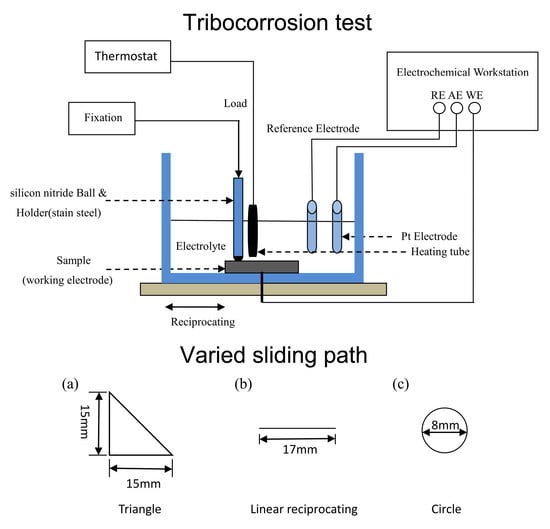
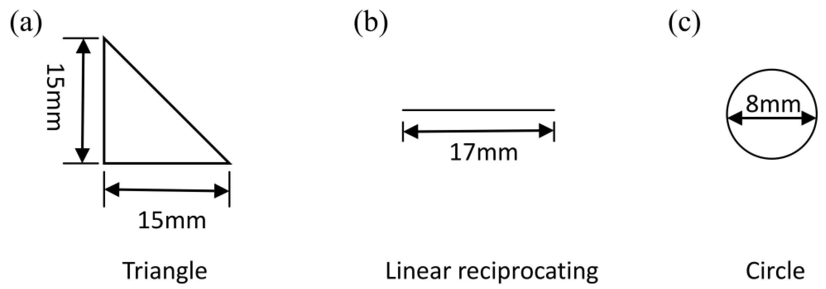
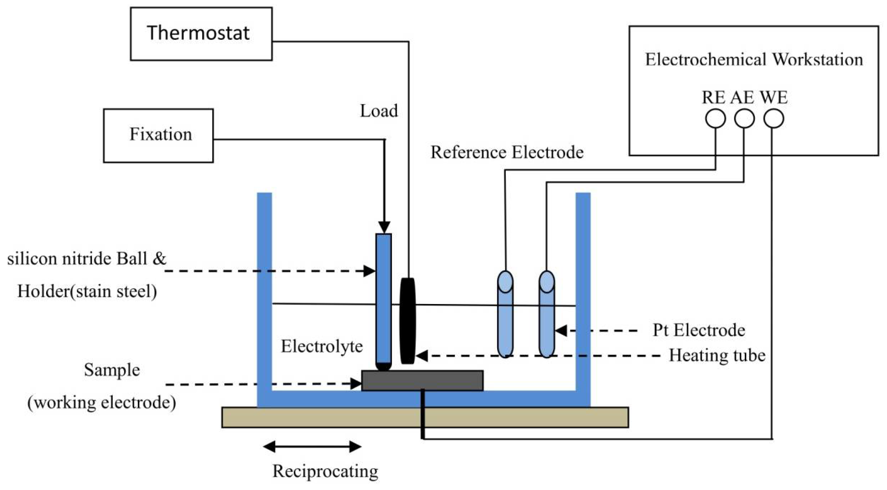
2.3. TribocorrosionTests

A tribo-electrochemical approach was used to study the tribocorrosion behaviour of the amorphous coating against silicon nitride ball. The schematic diagram of the tribocorrosion test is shown in Figure 2. The sample was fixed in the electrolytic cell with the desired surface facing upwards with an exposed volume to the test solution of 1 cm2. To simulate body fluid, the electrolyte chosen in the electrolytic cell was normal saline (0.9% NaCl solution) or phosphate-buffered solution (PBS), and kept at 37.5 ± 0.2 °C. The electrolytic cell was mounted on a mobile platform, and different sliding paths, including the linear reciprocating, as shown in Figure 1, were performed in the tribocorrosion experiments, respectively. A three-electrode system was connected to the electrochemical workstation, and the polarization curve was obtained during sling wear.

3. Results and Discussion

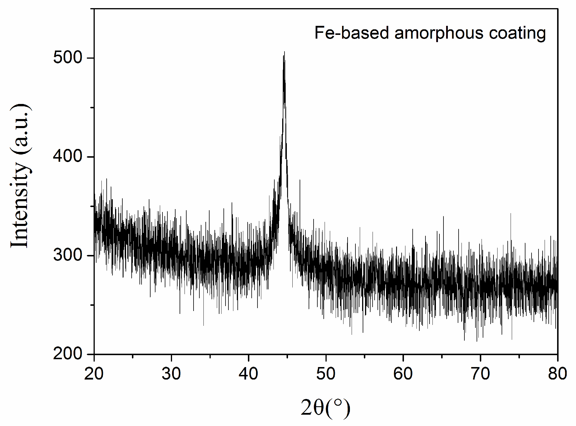
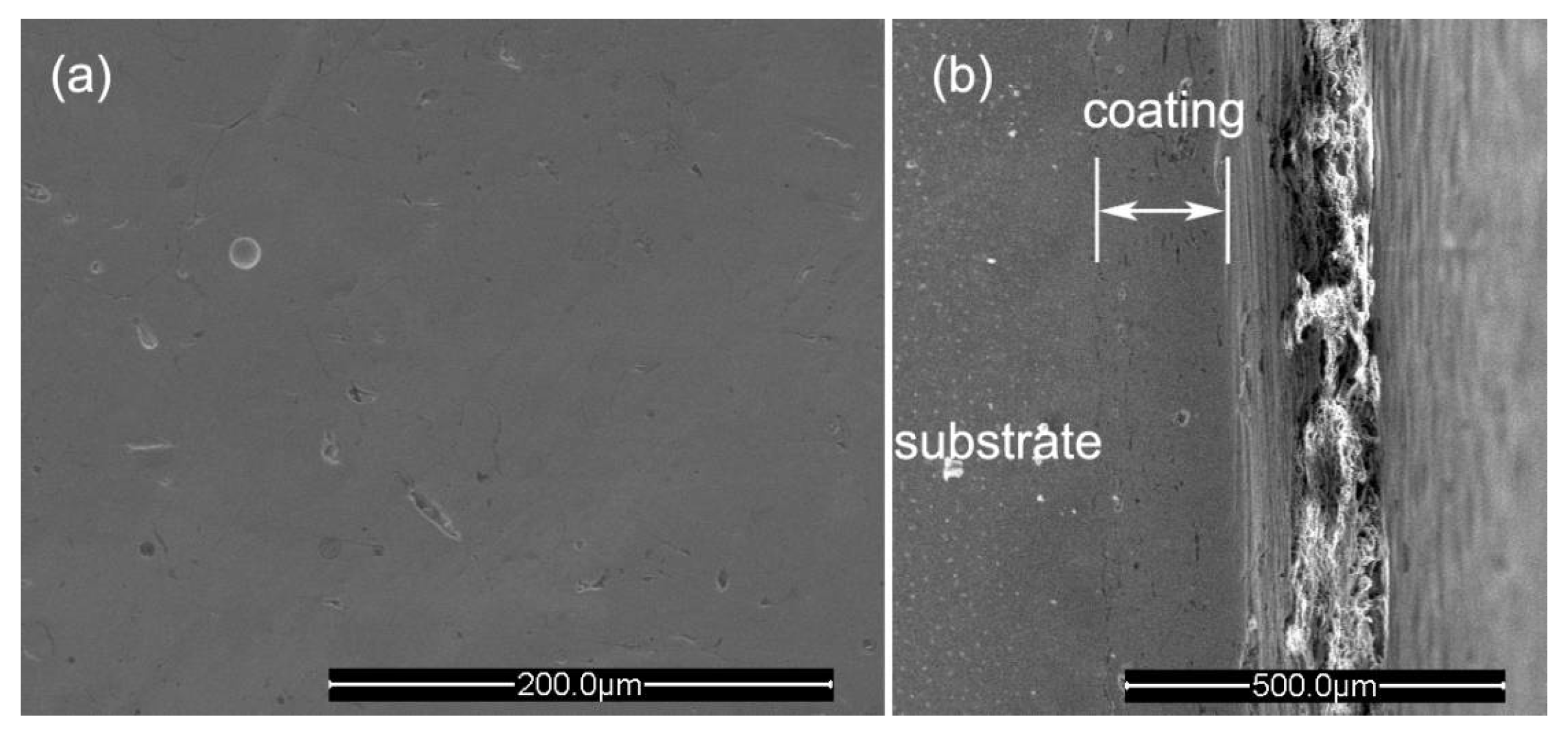
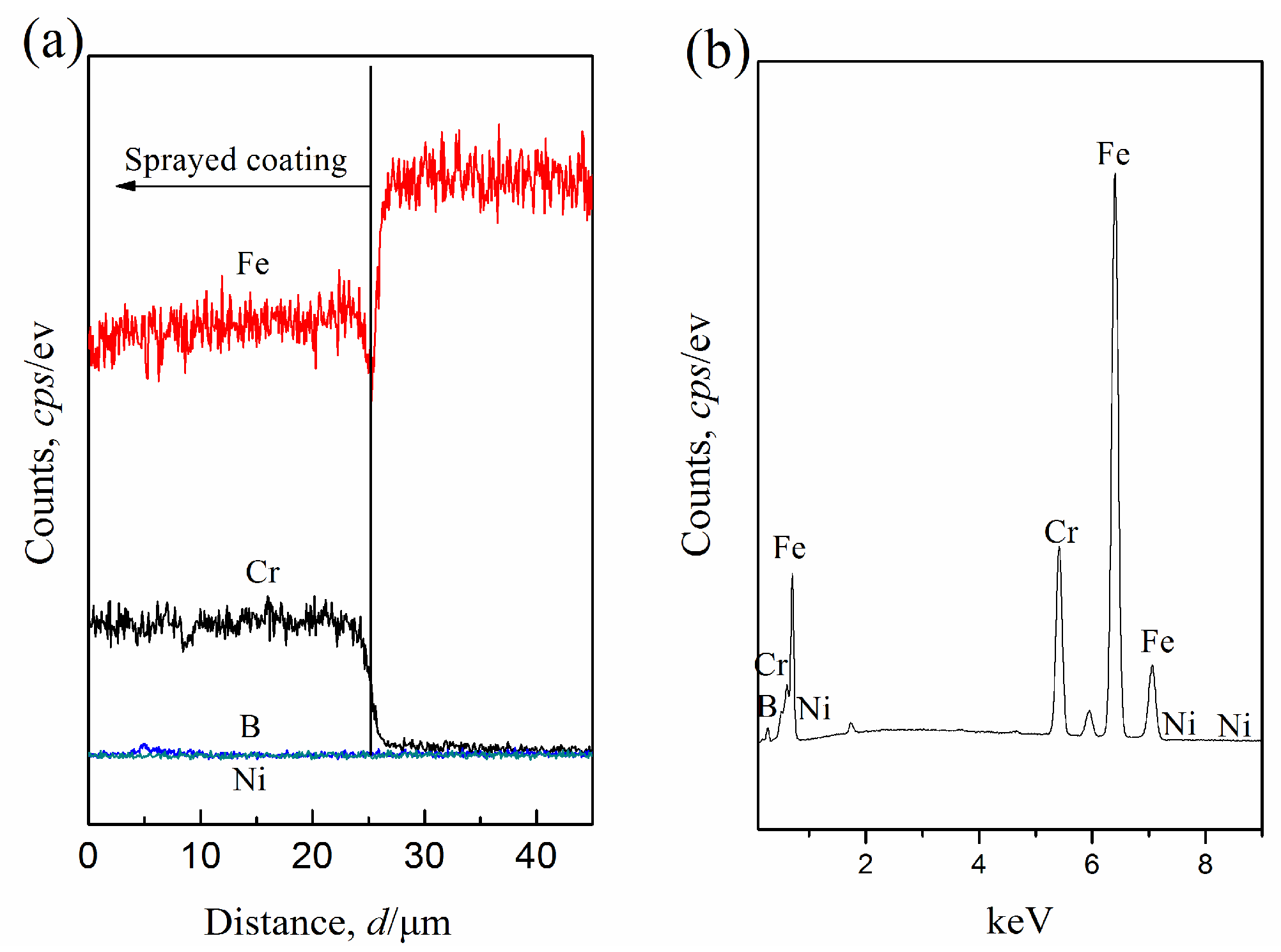
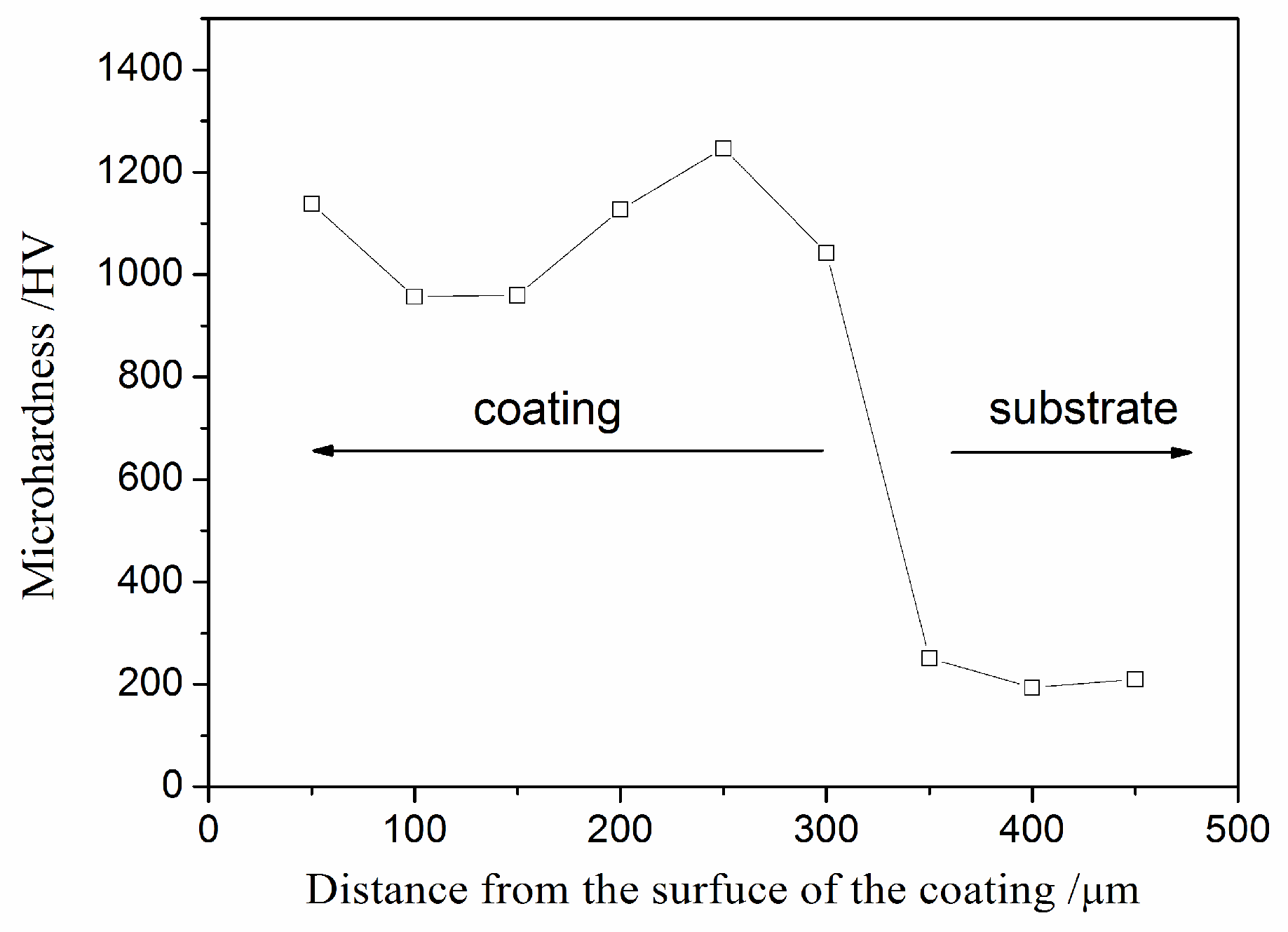
3.1. Microstructure and Hardness
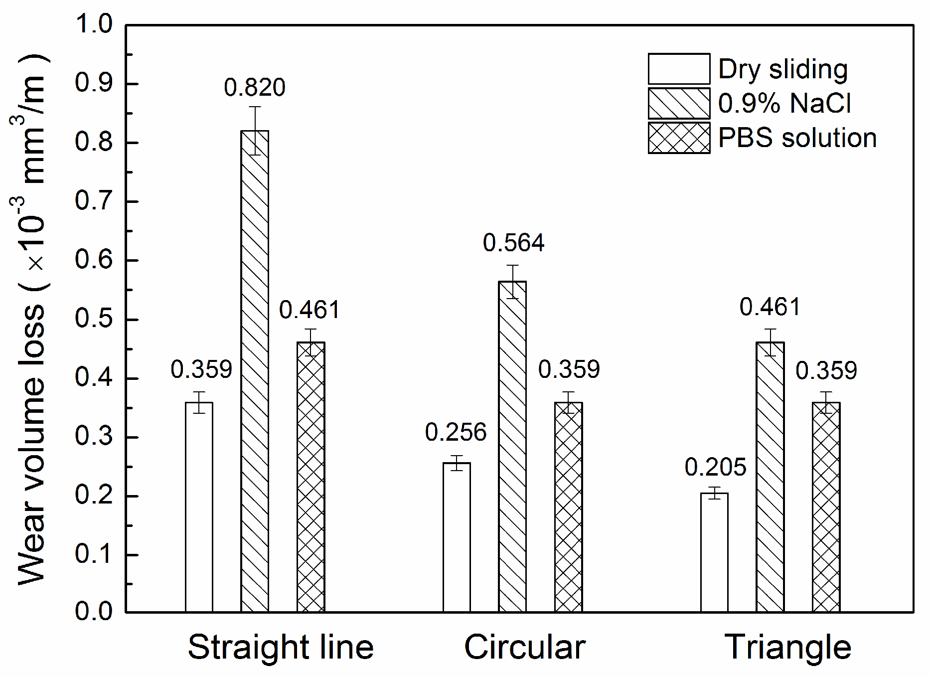
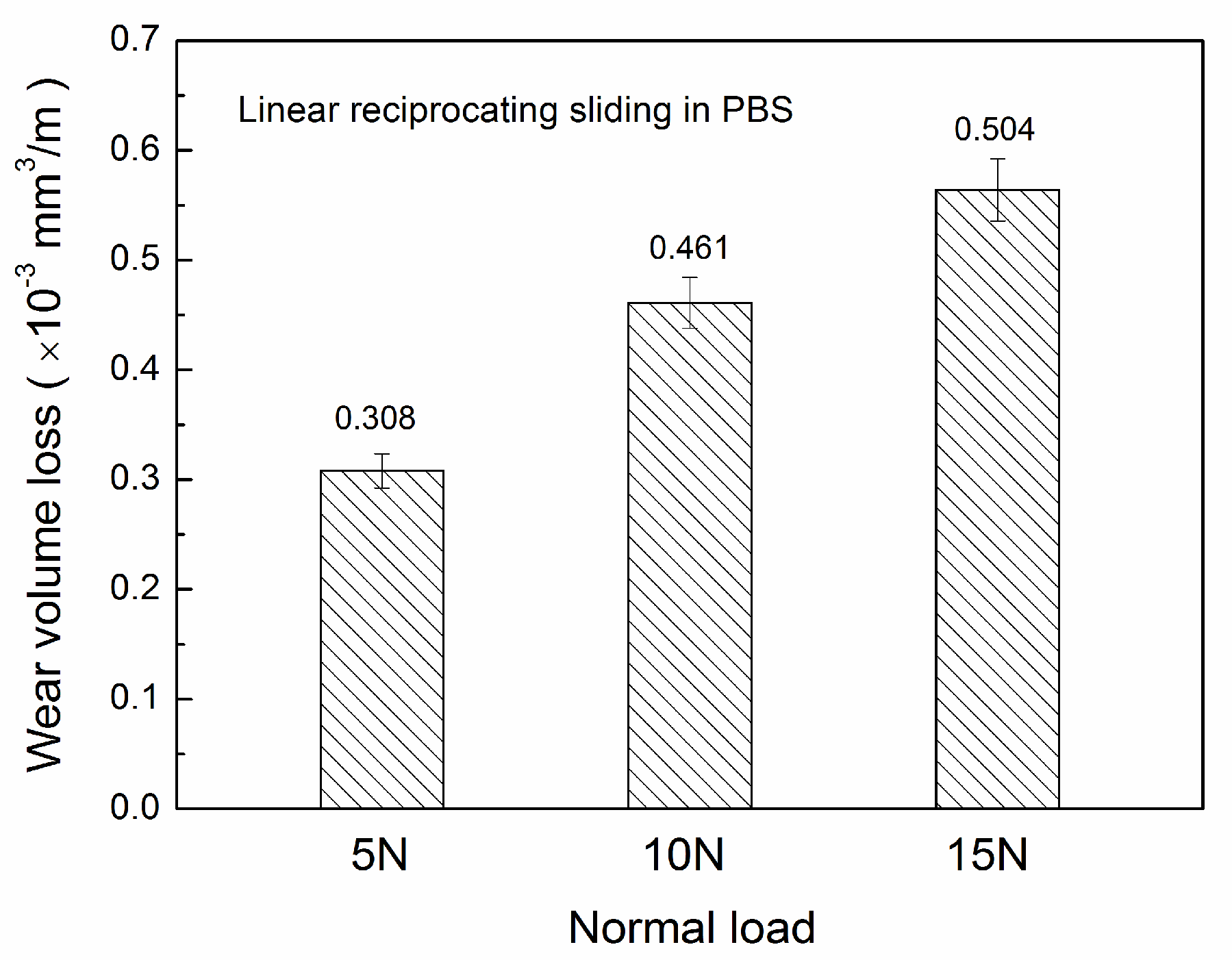
Figure 3 shows the XRD pattern of the coating. A broad diffraction halo appears at 2θ of 45° with a small amount of overlapping crystalline diffraction peaks in the coating. This indicates that the coating is amorphous in form, and the amorphous content is evaluated with the Jade software package is about 86% [7]. The results show that an Fe-based amorphous alloy coating is successfully prepared by arc spraying. Figure 4 shows the morphology of the coating, as well as the cross-section. The coating possesses a laminar structure, and it contains some defects, such as microcracks and pores. The thickness of the coating is about 200 μm. The main elements of the coating obtained from the EDS analysisare iron, and the content of iron is up to 81.17%, as listed in Table 3, as per the EDS spectra shown in Figure 5. The porosity of the amorphous coating calculated by ImageJ software is about 6.7%. Figure 6 shows the microhardness of the Fe-based amorphous coating from the surface to the substrate. The average microhardness of the coating is about 1082.5 HV0.2, and is about four times higher than that of the substrate.

3.2. Wear Loss

Sliding wear was performed under dry conditions, and in normal saline (0.9% NaCl solution) and phosphate buffer solution (PBS) with linear reciprocating, circular, and triangular paths. Figure 7 shows the effects of solutions and paths on the wear volume losses of coatings. As it can be seen, the volume losses with the linear path are higher than those with circular and triangle paths. The possible reason is that the sliding direction of the linear path always changes, and the changing direction helps to pull out abrasive debris, exposing the underlying coating and accelerating the wear of the coating. The volume losses in 0.9% NaCl solution are higher than those in dry and PBS. This indicates that the ions present in the solution accelerate the wear, leading to a stronger effect of 0.9% NaCl than PBS on wear loss [14].
The relationship between the normal load and the wear loss in PBS was shown in Figure 8. With the increase of load, the wear loss of the amorphous coating increases approximately linearly. Since some fragments of amorphous coating may easily fall off under high load, the mass loss increases at high load [15]. On the other hand, the limit plastic deformation of amorphous coating may cause the combination between inter-splats to relax, andmay also create microcracks along the boundary of flattened particles.
The wear losses of the amorphous coating and the 316L SS were also detected in PBS solution under the load of 10 N, and they are 0.461 × 10⁻³ mm3·m−1 and 0.783 × 10⁻³ mm3·m−1, respectively. This means the wear loss of the 316L SS is higher than that of the amorphous coating, suggesting the wear resistance of amorphous coating is better than 316L SS in PBS. High hardness contributes to the good tribocorrosion resistance of the amorphous coating.

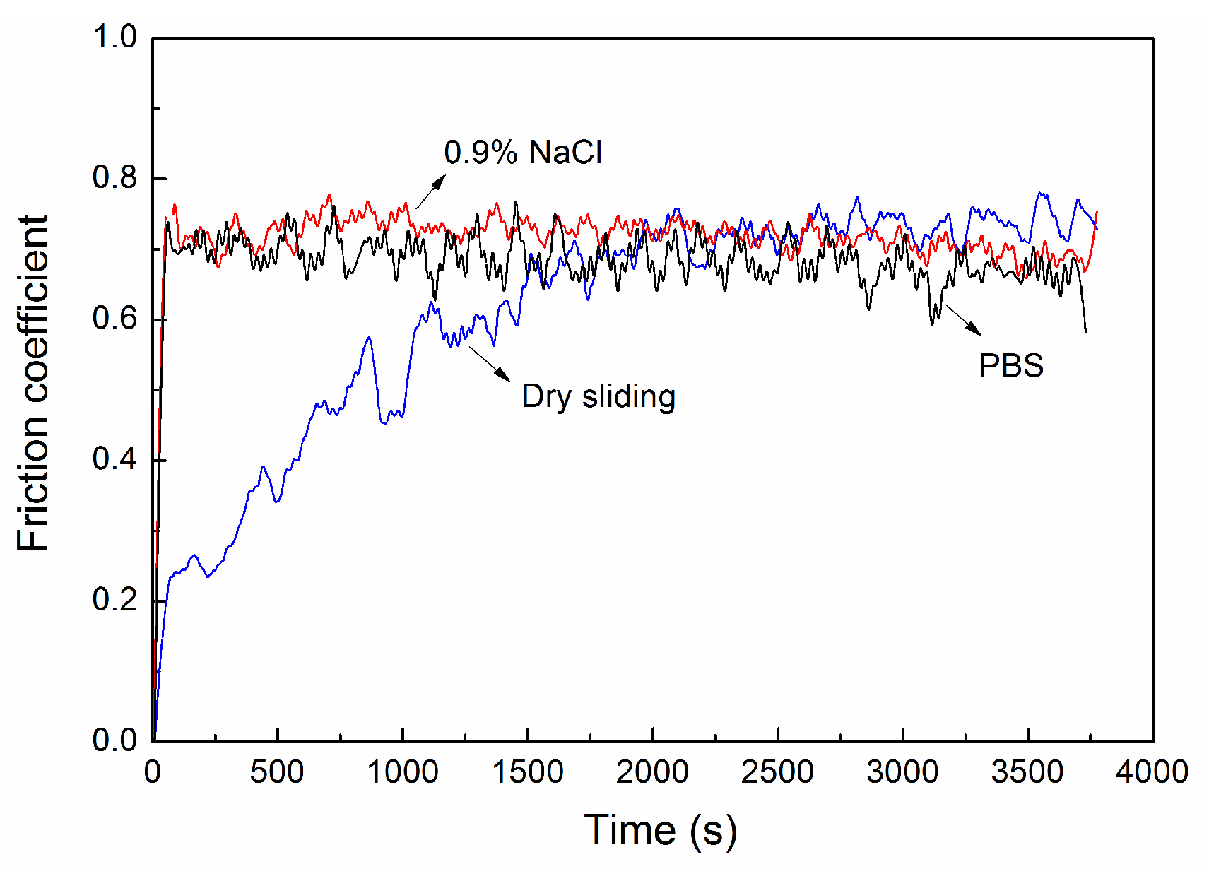
3.3. Friction Coefficient

Figure 9 shows the variation of the friction coefficient (COF) with the sliding time for the amorphous coatings in different environments. All of the average COF values in three different environments are close to about 0.7. Meanwhile, steady-state COF under dry conditions is slightly higher than that in 0.9% NaCl and PBS. This indicates the solution acts as a lubricant and reduces the friction, which results in a low friction coefficient. At the same time, the sliding wear reaches into steady wear period quickly in 0.9% NaCl or PBS, while the sliding wear takes a longer time for the running-in period in dry conditions. Thus, the solutions are also beneficial to speed up the running-in process.

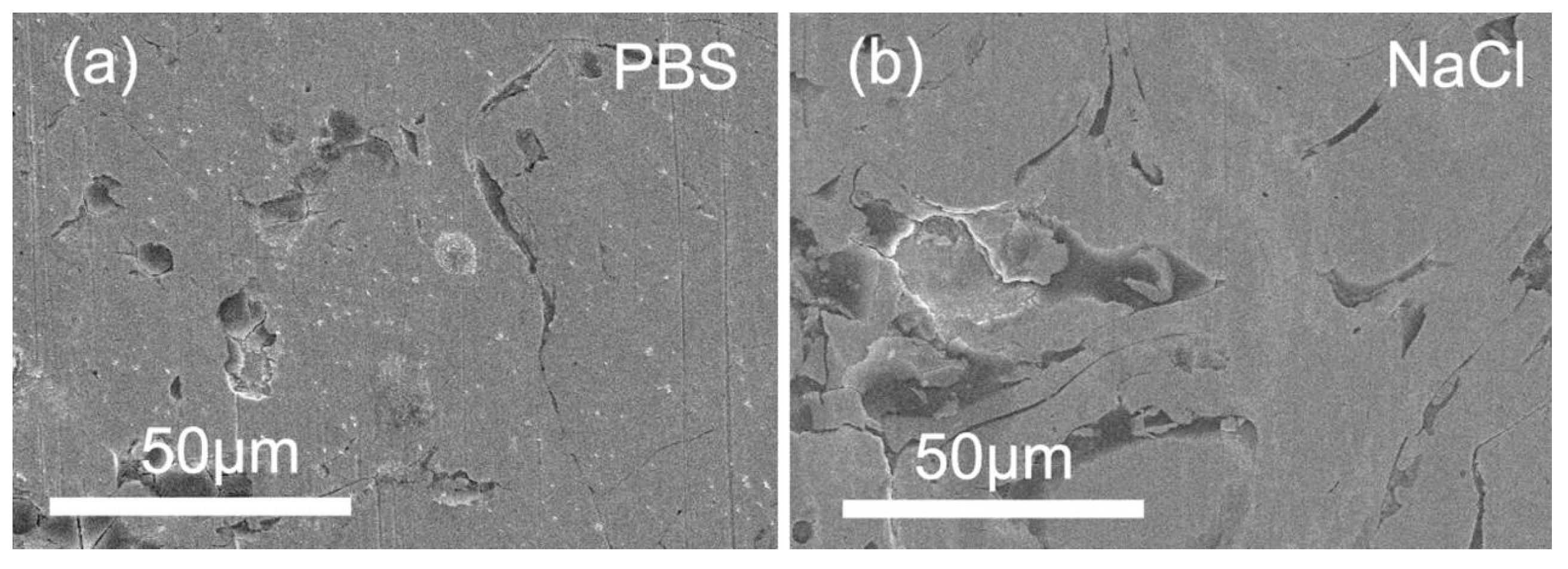
3.4. Wear Topography

The SEM images for the typical worn surface morphologies of the amorphous coatings are represented in Figure 10. As it can be seen, the worn surface of the amorphous coating is smooth and some fine scratches parallel to the sliding direction in PBS [14]. There are slender grooves and very small wear debris on the surface, suggesting the wear mechanism of amorphous coatings in PBS is abrasive wear and the microfracture is related to the laminate structure. Tribocorrosion is worse for sliding wear in 0.9% NaCl. The coating pullout occurs on the surface in 0.9% NaCl, and the reason may be that the microcrack initiation under the wear leads to the coating flaking. Meanwhile, the sharp edge indicates the appearance of a layered brittle fracture, and the wear mechanism of coatings may include abrasive wear accompanied with corrosive wear [11].

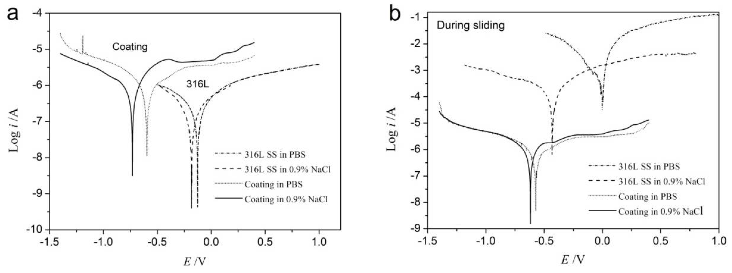
3.5. Tribocorrosion Behaviour

The static and dynamic polarization curves of amorphous coatings and 316L SS in different environments are shown in Figure 11. Dynamic polarization curves were obtained during sliding with a speed of 500 mm·min−1 under 0.9% NaCl and PBS solution, respectively. The corrosion current density (Icorr) and corrosion potential (Ecorr) for the evaluation of the corrosion resistance were deduced from Tafel extrapolation of static and dynamic polarization curves and listed in Table 4. Convection and agitation are present in the solution during sliding, and the depolarization of oxygen is promoted, which lead to the positive shift of corrosion potential. While the destruction of oxide film may accelerate the tendency of corrosion during sliding, which lead to the negative shift of corrosion potential. The shift of corrosion potential is affected by the combination of these two factors. In the static situation, the Icorr of 316L SS in 0.9% NaCl or PBS solution is slightly lower than that of the amorphous coating. However, in the dynamic situation, the Icorr of 316L SS is much higher than that of amorphous coating in 0.9% NaCl or PBS solution. By Faraday’s law, the corrosion rates of amorphous coating under 0.9% NaCl and PBS solution calculated are both about 0.011 mm·a−1 while, for 316L SS, the corrosion rates under 0.9% NaCl and PBS are 1.123·mm·a−1 and 7.542·mm·a−1, respectively. The corrosion rates of 316L SS are significantly faster than the amorphous coating. It reveals that the amorphous coating possesses better tribocorrosion resistance than 316L stainless steel. Since the good corrosion resistance of 316L SS comes from the dense oxide film formed from the chemical reaction between stainless steel surface and solution, Icorr of 316L SS increases obviously when the protective film is wiped off and fresh surface is exposed in the corrosive environment. In other words, the ablation of the wear friction displaces the corrosion product from the surface and exposes the underlying non-corroded place to the immersion solution [9]. For the different corrosion mechanism, the amorphous coating exhibits worse corrosion resistance in static situations because of the solidification defects, including micropores and microcracks formed from arc spraying. Additionally, it shows better corrosion resistance in dynamic situations for its instinct facts, such as without clear grain boundaries.

4. Conclusions

The arc-sprayed Fe-based amorphous coating with laminar structure was prepared, which contains about 86% amorphous phase and 6.7% porosity, and the average microhardness 1082.5 HV0.2. The sliding path influenced the wear loss strongly, and the volume wear loss with the linear path is higher than those with circular and triangle paths. In PBS solution with the load of 10 N, the wear losses of the amorphous coating and the 316L stainless steel are 0.461 × 10⁻³ mm3·m−1 and 0.783 × 10⁻³ mm3·m−1, respectively, which means the wear resistance of the amorphous coating is better than 316L SS. Since the ions in the solution accelerate the wear, the volume loss of the amorphous coating in 0.9% NaCl solution is higher than those that are dry or in PBS solution. With the increase of the load, the wear losses increased approximately linearly. The average friction coefficient for amorphous coating is about 0.7 during dry sliding, which is a little higher than it in 0.9% NaCl and PBS solution because they act as a lubricant. The typical worn surface morphologies of the amorphous coatings show the wear mechanism of amorphous coating in dry and PBS is abrasive wear, while it may include abrasive wear accompanying with corrosion wear in 0.9% NaCl. The amorphous coating exhibits better tribocorrosion resistance than 316L SS during sliding wear.

Acknowledgments

This research was supported by the National Natural Science Foundation of China (51475140), the Postgraduate Research and Practice Innovation Program of Jiangsu Province (KYCX17_0536), and the fundamental research funds for the central universities (2017B717X14).

Author Contributions

Xiulin Ji and Cuicui Ji conceived and designed the experiments; Chanyuan Luo performed the experiments; Yingtao Zhang analyzed the data; Hui Wang contributed analysis tools; Chanyuan Luo wrote the paper.

Conflicts of Interest

The authors declare no conflict of interest.

References

  1. Zivic, F.; Babic, M.; Mitrovic, S.; Vencl, A. Continuous control as alternative route for wear monitoring by measuring penetration depth during linear reciprocating sliding of Ti6Al4V alloy. J. Alloys Compd. 2011, 509, 5748–5754. [Google Scholar] [CrossRef]
  2. Alves, S.A.; Bayón, R.; Viteri, V.S.D.; Garcia, M.P.; Igartua, A.; Fernandes, M.H.; Rocha, L.A. Tribocorrosion Behavior of Calcium and Phosphorous-Enriched Titanium Oxide Films and Study of Osteoblast Interactions for Dental Implants. J. Bio Tribo Corros. 2015, 1, 1–23. [Google Scholar] [CrossRef]
  3. Choi, S.J.; Lee, H.S.; Jang, J.W.; Yi, S. Corrosion behavior in a 3.5 wt% NaCl solution of amorphous coatings prepared through plasma-spray and cold-spray coating processes. Met. Mater. Int. 2014, 20, 1053–1057. [Google Scholar] [CrossRef]
  4. Johnson, W.L. Bulk amorphous metal—An emerging engineering material. JOM 2002, 54, 40–43. [Google Scholar]
  5. Inoue, A.; Shinohara, Y.; Gook, J.S. Thermal and Magnetic Properties of Bulk Fe-based Glassy Alloys Prepared by Copper Mold Casting. Mater. Trans. JIM 1995, 36, 1427–1433. [Google Scholar] [CrossRef]
  6. Wang, Y.B.; Li, H.F.; Cheng, Y.; Wei, S.C.; Zheng, Y.F. Corrosion performances of a Nickel-free Fe-based bulk metallic glass in simulated body fluids. Electrochem. Commun. 2009, 11, 2187–2190. [Google Scholar] [CrossRef]
  7. Lin, J.; Wang, Z.; Lin, P.; Cheng, J.; Zhang, J.; Zhang, X. Microstructure and Corrosion Resistance of Fe-Based Coatings Prepared by Twin Wires Arc Spraying Process. J. Therm. Spray Technol. 2013, 23, 333–339. [Google Scholar] [CrossRef]
  8. Kobayashi, A.; Yano, S.; Kimura, H.; Inoue, A. Mechanical property of Fe-base metallic glass coating formed by gas tunnel type plasma spraying. Surf. Coat. Technol. 2008, 202, 2513–2518. [Google Scholar] [CrossRef]
  9. Lee, H.B.; Wu, M.Y. A Study on the Corrosion and Wear Behavior of Electrodeposited Ni–W–P Coating. Metall. Mater. Trans. A 2017, 48, 4667–4680. [Google Scholar] [CrossRef]
  10. Cheng, J.B.; Wang, Z.H.; Xu, B.S. Wear and Corrosion Behaviors of FeCrBSiNbW Amorphous/Nanocrystalline Coating Prepared by Arc Spraying Process. J. Therm. Spray Technol. 2012, 21, 1025–1031. [Google Scholar] [CrossRef]
  11. Ji, X.; Wang, H.; Bao, Y.; Zheng, D. Wear resistance of CuZr-based amorphous-forming alloys against bearing steel in 3.5% NaCl solution. Philos. Mag. 2017, 97, 3042–3054. [Google Scholar] [CrossRef]
  12. Tao, P.; Yang, Y.; Xie, Z.; He, Y. Research on friction and wear behavior of a bulk metallic glass under different sliding velocity. Mater. Lett. 2015, 156, 177–179. [Google Scholar] [CrossRef]
  13. Bennett, D.; Humphreys, L.; O’Brien, S.; Kelly, C.; Orr, J.; Beverland, D.E. The influence of wear paths produced by hip replacement patients during normal walking on wear rates. J. Orthop. Res. 2008, 26, 1210–1217. [Google Scholar] [CrossRef] [PubMed]
  14. Munoz, A.I.; Mischler, S. Effect of the environment on wear ranking and corrosion of biomedical CoCrMo alloys. J. Mater. Sci. Mater. Med. 2011, 22, 437–450. [Google Scholar] [CrossRef] [PubMed]
  15. Cheng, J.; Liu, D.; Liang, X.; Chen, Y. Wear Behaviors of Arc-Sprayed FeBSiNb Amorphous Coatings. Tribol. Lett. 2015, 60, 22. [Google Scholar] [CrossRef]
Figure 1. Three kinds of sliding paths used in the tribology tests.
Lubricants 06 00037 g001
Figure 2. Schematic diagram of the tribocorrosion tester.
Lubricants 06 00037 g002
Figure 3. XRD pattern of the Fe-based amorphous coating.
Lubricants 06 00037 g003
Figure 4. SEM images of the front (a) and the cross-section (b) of the amorphous coating.
Lubricants 06 00037 g004
Figure 5. The EDS spectra of the amorphous coating with linear scanning (a) and surface scanning (b).
Lubricants 06 00037 g005
Figure 6. Microhardness of the cross-section of the amorphous coating.
Lubricants 06 00037 g006
Figure 7. Effect of the environments and sliding paths on the wear loss of the amorphous coating.
Lubricants 06 00037 g007
Figure 8. Relationship between the wear loss of amorphous coating and the normal load.
Lubricants 06 00037 g008
Figure 9. Friction coefficient evolution with the sliding time for the amorphous coating in different environments.
Lubricants 06 00037 g009
Figure 10. SEM images of the worn amorphous coatings in (a) PBS solution and (b) 0.9% NaCl.
Lubricants 06 00037 g010
Figure 11. Polarization curves of amorphous coating and 316L SS obtained in 0.9% NaCl and PBS solutions under (a) static and (b) dynamic situations, respectively.
Lubricants 06 00037 g011
Table 1. Chemical composition of Q345 low-alloy steel.
ElementCSiMnPSVNb
Content (wt %)≤0.2≤0.551.0–1.6≤0.045≤0.0450.02–0.150.015–0.06
Table 2. Chemical composition of AISI 316L stainless steel.
ElementCSiMnPSCrNiMo
Content (wt %)≤0.08≤1.0≤2.0≤0.035≤0.0316.0–18.510.0–14.02.0–3.0
Table 3. Chemical composition of the amorphous coating.
ElementBCrNiFe
Content (wt %)2.4016.290.1481.18
Table 4. Icorr and Ecorr obtained from the static and dynamic polarization curves for the amorphous coatings comparing with 316L.
Materials and EnvironmentsStaticDynamic
Icorr (μA/cm2)Ecorr (V) Icorr (μA/cm2)Ecorr (V)
316L in PBS0.174−0.126644.6−0.002
316L in 0.9% NaCl0.103−0.18495.99−0.433
Amorphous coating in PBS0.786−0.5970.944−0.572
Amorphous coating in 0.9% NaCl0.664−0.7310.907−0.619

