Article

Measured and Predicted Operating Characteristics of a Tilting-Pad Journal Bearing with Jacking-Oil Device at Hydrostatic, Hybrid, and Hydrodynamic Operation

Institute of Tribology and Energy Conversion Machinery, Clausthal University of Technology, 38678 Clausthal-Zellerfeld, Germany
*
Author to whom correspondence should be addressed.
Lubricants 2018, 6(3), 81; https://doi.org/10.3390/lubricants6030081
Submission received: 19 July 2018 / Revised: 20 August 2018 / Accepted: 30 August 2018 / Published: 10 September 2018
(This article belongs to the Special Issue Fluid-Film Lubrication)

Abstract

:
Jacking-oil pockets are applied in many journals and thrust bearing applications in order to provide a hydrostatic oil film force that ensures a wear free run-up following a successful lift-off procedure. However, all components of the jacking-oil system have to be carefully designed in order to limit costs and prevent significant disturbance of hydrodynamic operation after deactivation of lift-oil. Experimental data and predictions for a four-pad tilting-pad journal bearing in load between pivot configuration are presented. Dynamic processes of the lift-off procedure as well as characteristic parameters of stationary conditions are studied. Moreover, hydrodynamic operation and hybrid lubrication providing a combined hydrodynamic and hydrostatic pressure distribution are investigated for sliding speeds up to 20 m/s. Analyzes of lift-off procedure prove that characteristic parameters such as lift-off pressures and vertical lift displacements are considerably influenced by manufacturing tolerances and misalignments. The comparison of hydrodynamic and hybrid lubrication provides a significant increase of load carrying capacity by additional jacking-oil supply at the maximum journal speed. In summary, results of measurements and predictions correlate well for all three investigated lubrication conditions.

Graphical Abstract

1. Introduction

Many application areas of hydrodynamically lubricated journal bearings require lift-oil or jacking-oil pockets on the sliding surfaces of the bearing pads located in load direction. During start-up or run-down of a machine, these pockets are fed with a high pressure oil pump in order to generate a fluid film force that ensures a complete separation of the sliding surfaces in the entire lubricant gap. Consequently, this enables a wear-free operation of the machine in low-level speed ranges and avoids bearing damages. The entire lift-oil system consisting of the pump, pockets on the sliding surface and all pipe and valve elements located in between has to be carefully designed to ensure sufficiently high pressure levels in the film for a successful lift-off process as well as safe operation if the lift-oil system is deactivated. Simultaneously, the limits for supply pressure as well as jacking-oil flow rate have to be considered in order to restrict costs.
The necessity of a lift-oil device for a certain application is a question of bearing material, specific bearing load and the number of start and stops. For whitemetal bearings Neale [1] gives 1.4 MPa as an upper limit of specific bearing load at start-up if the machine runs start and stop procedures several times a day. If the number of starts is reduced to once a day this value increases to 2.5 MPa. Design parameters of different hydrostatic jacking systems for thrust bearings from literature are listed in [2]. Several publications investigate operation of hybrid journal bearings building up a combined hydrostatic and hydrodynamic pressure, e.g., [3]. Varela and Santos, e.g., [4,5], present different investigations on active controllable journal bearings based on hydrostatic actuators. Only few publications are available investigating lift procedures at zero journal rotation. In this particular case, two states are of special interest. The first one is the breakaway process requiring the maximum oil feed pressure and defining the initial state of the dynamic lifting procedure. The second one is the holding pressure that is reached as a final state before the journal starts to rotate. Elwell [6] presents an empirical equation for the breakaway pressure, which depends on geometry, load and additional test data. Raud et al. [7] study the impact of jacking-oil pockets on steady state conditions of a large tilting-pad bearing with a special emphasis on misalignment between journal and bearing. Beside their nominal applications, lift-oil devices can be used as a short-term measure if field issues occur. Buchhorn et al. [8] report on a reduction of maximum measured pad temperature by up to ΔT = 10 K by activating the hydrostatic assistance system at rated operating conditions of a large turbine tilting-pad journal bearing. The authors relate this behavior to a combined effect of thermo-hydrodynamics and deformation.
Kluitenberg and Childs [9] investigate the impact of deactivated lift-oil pockets on dynamic coefficients for a four-pad tilting-pad journal bearing. The authors contrast their results with the ones identified by Tschoepe and Childs [10] for the same bearing without any lift-oil device. A significant decrease of main damping coefficients compared to the initial bearing configuration is detected. Hagemann et al. [11] and Kukla et al. [12] consider the geometrical influence of jacking-oil pockets in their analyses without determining their specific impact on their results. In their case, the jacking-oil pockets are machined into the white metal layer, however, without a bore communicating to an outer high pressure supply system or a check valve. Raud et al. [7] compare predictions with and without jacking-oil pockets and obtain significant influences of the concrete configuration on the journal displacement, shaft friction torque and minimum film thickness.
This paper presents an experimental and theoretical analysis of the less investigated lift process at zero journal rotation with lift-oil devices. Dynamic and stationary conditions are studied. Furthermore, hybrid lubrication with a combined hydrostatic and hydrodynamic pressure distribution as well as the impact of deactivated jacking-oil pockets on hydrodynamic operation are investigated.

2. Materials and Methods

2.1. Theoretical Model

2.1.1. Governing Equations

The governing equations of the applied bearing model including a specification of their numerical implementation are comprehensively introduced in [11,13]. Following the brief specifications given for this model in [14] and additionally assuming laminar flow the determination of fluid flow and pressure distribution p in the lubricant gap is based on a two-dimensional (2D) extended and generalized Reynolds equation:
x ( F 2 p x ) + z ( F 2 p z ) = U x [ Θ ( h F 1 F 0 ) ]  
Due to three-dimensional (3D) variable temperature distribution in the lubricant film, Equation (1) considers the impact of radial variable fluid viscosity η by the following factors using the radial coordinate y and the local film thickness h [15]:
F 0 = 0 h d y η , F 1 = 0 h y η d y , F 2 = 0 h y η ( y F 1 F 0 ) d y  
The parameter Θ represents the relation between the local and the nominal lubricant density. The 3D energy equation for a steady, incompressible and laminar fluid film applied to determine local lubricant temperature T is given by:
c ρ ( u T x + v T y + w T z ) = x ( λ T x ) + y ( λ T y ) + z ( λ T z )   + Φ
Here, Φ is the dissipation function based on shear stresses in the fluid and u, v, and w are the flow velocities. In the solid bodies of the bearing heat conduction equations are applied that can be derived from Equation (3) by neglect of dissipation and convective heat transfer. While a stationary 3D profile is established for the pad region the temperature distribution in the journal is assumed to be 2D as the temperature does not vary in circumferential direction due to sufficiently high rotor speeds at hydrodynamic operation. These equations are the basis of the subsequently used bearing model. Based on its general approach, the model further includes all effects of major influence such as cavitation and deformations. Moreover, its extensions to turbulent flow are described in [11,14]. However, except for deformations, these effects are not relevant for this study. The model accounts for hydraulic, mechanical and energetic interactions between the bearing components. It is flexible to consider different boundary conditions, and comprehensively described in [11,13,14]. The numerical implementation is validated for different applications of hydrodynamic operation in [11,12,13,14,16,17,18].

2.1.2. Oil Inlet Boundary Conditions
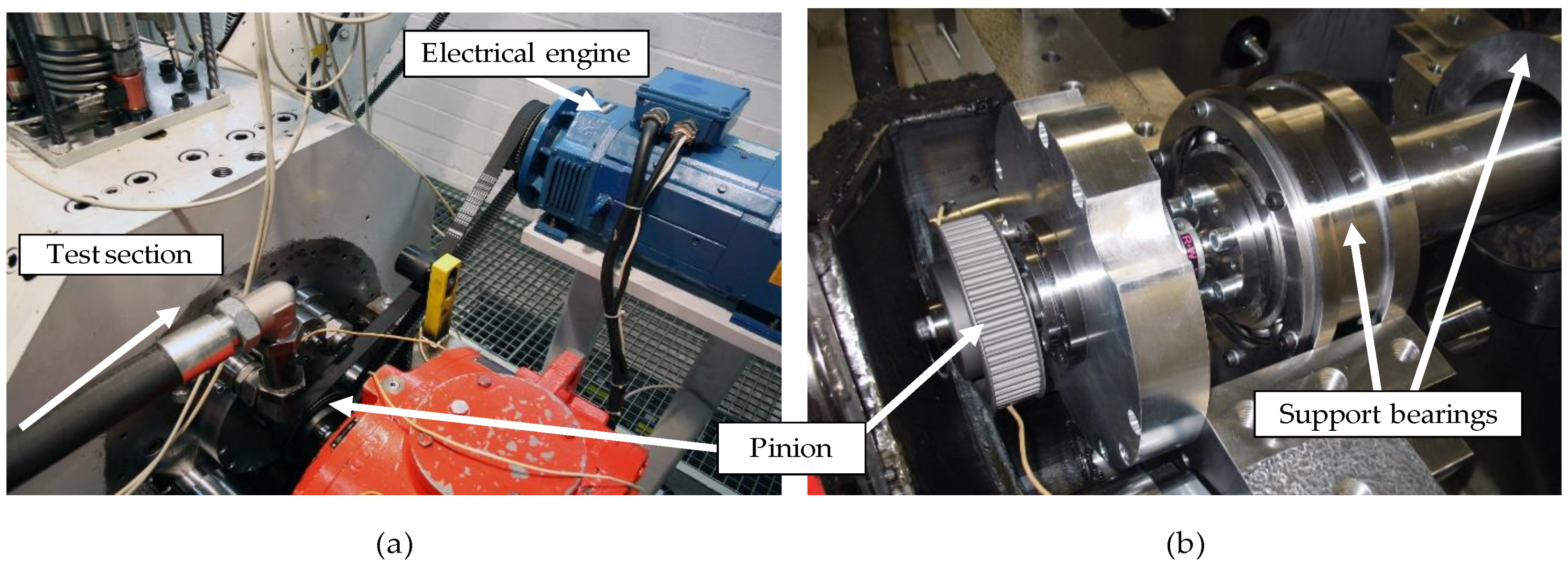
The jacking-oil pocket pressure is defined as a boundary condition for the extended and generalized Reynolds equation (1) and is assumed to be constant within the pocket area except on the axial interfaces to the pad region. Here, a pressure loss due to inertia effects is considered according to Ref. [19]. A balance of the flow rates across the pocket boundaries that are derived from the solution of Equation (1) provides the inlet flow rate of each pocket. The throttles between the oil supply system and the pockets define the relation between the particular pocket pressure and the outer feed pressure. The effective pocket pressure is determined iteratively. In the spaces between pads a constant lube oil flow rate is supplied and the pressure level equals the ambient one. The entire oil flow and fluid temperature inlet model is comprehensively described and validated in Ref. [14].

2.2. Test Rig

The test rig applied for the experimental investigations was earlier presented in Ref. [16,17]. Following generally the same description used in Ref. [16] for a setup for investigations of journal test bearings the test section is depicted in Figure 1a. The test shaft (1) is supported by two fluid-film journal bearings (2, 3). The test bearing (4) is mounted in a test bearing housing (5). A self-aligning coupling (6) connects the drive train with the test shaft (1). The test bearing is virtually unconstrained adjustable in the radial plane and it is aligned by six transversely flexible chains (7). Rods (9) connect the test bearing housing to a double-acting pneumatic bellow compensator (8) that applies static loads on the test bearing. Another compensator set, which is attached to the test bearing housing in a right angle, imposes horizontal load components. For wired signal transmission of the rotating sensors a rotary transmitter (10) is employed. The film pressure and thickness are measured by rotating sensors. Furthermore, displacement sensors detect the relative motion between rotor and stator motion. The test bearing and the supporting bearings are lubricated separately. The lubricant supply pressure, temperature and flow rate are measured for each bearing.
In opposite to Ref. [16,17] the following modifications are conducted to enable low rotational speeds at high mechanical loads. Rolling element bearings substitute the two fluid-film support bearings according to Figure 1b. The drive unit formerly consisting of a 630-kW electrical engine and a planetary gearbox with a transmission ratio of I = 5 is replaced by a 14-kW electrical engine with a maximum speed 3150 rpm. The modified drive unit depicted in Figure 2 is mounted parallel to the original one and connected to the test shaft by a gear belt with a transmission ratio of i = 1. Therefore, operation at low journal speeds is enabled. An axial piston pump providing a constant oil flow rate feeds the jacking-oil pockets.

2.3. Test Bearing and Instrumentation

The test bearing is a four-pad tilting-pad journal bearing with a directed lube oil supply via three nozzles located in each space between pads. The original bearing is studied in Ref. [18] at hydrodynamic operation and without jacking-oil pockets as shown in Figure 3a. Figure 3a additionally illustrates the load configuration for the subsequent investigations as well as the positions of the pad temperature sensors, which are located 4.25 mm below the sliding surface in the lateral middle plane of the bearing. Moreover, the nomenclature of the pads is included here. Figure 3b presents the modified test bearing with one jacking-oil pocket on each of the two highly loaded pads number 2 and 3. The jacking-oil pockets are located axially symmetric to the lateral middle plane and symmetrically to the rocker pivot line of the pad. The jacking-oil pockets are manufactured with a constant radius and merge to the sliding surface at their circumferential boundaries. Table 1 provides comprehensive quantitative information on the test bearing.
Beside the stator-sided temperature sensors in Figure 3a, pad number 3 features two piezoresistive pressure sensors measuring pressure in the jacking-oil supply bore and slightly behind the pocket in positive direction of rotation. The measurement positions are signed in Figure 3b by the bores the sensors communicate with. Furthermore, eight eddy current proximity probes detect the displacement between the bearing housing and the journal. Figure 4 shows these sensors mounted on a ring at the drive end side of the bearing. Four sensors are located on both sides of the bearing with an offset of 90° between each other. The stator-sided proximity probes are applied to align the bearing housing relative to the journal in the test rig using the chains depicted in Figure 1a. On the measurement shaft an eddy current proximity probe and a piezoelectric pressure sensor are located in the middle plane of the bearing.
The uncertainties of the applied thermocouples in the measurement chain corresponds to ±1.5 K. The nominal uncertainties of the eddy current proximity probes are specified with ±2 µm for the stator-sided sensors and ±1 µm in case of the one integrated into the shaft. The non-repeatability of the pressure sensors are ±0.2 MPa for the piezoelectric probe in the shaft and approximately ±0.1 MPa for the piezoresistive ones in the pad. Additionally, the measurement target and the shape of the investigated surfaces provide variations in the analyzed data. Beside influences of curvatures, the journal is able to rotate and provides an out-of-roundness error for experiments at zero journal rotation. This value can be assessed by the opposite located proximity probes at very low journal rotation. The procedure is comprehensively described in Ref. [20] and determines an additional uncertainty of ±3 µm. Furthermore, the rolling element bearings provide a variable stiffness characteristic due to the relation between load and the rolling bodies. These two influences are minimized by repeating each measurement several times and evaluating the mean of it.

3. Results

3.1. Lift Procedure at Zero Journal Rotation

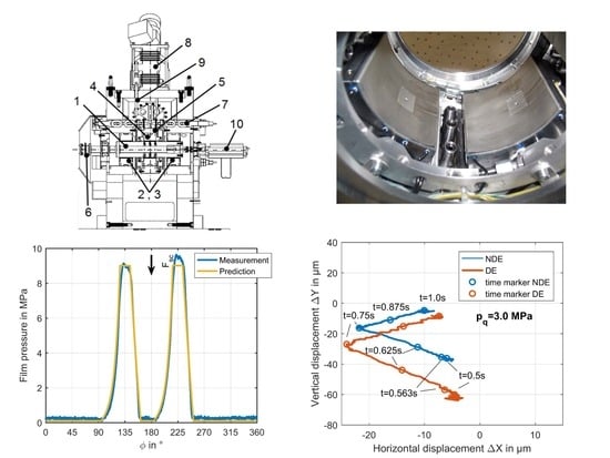
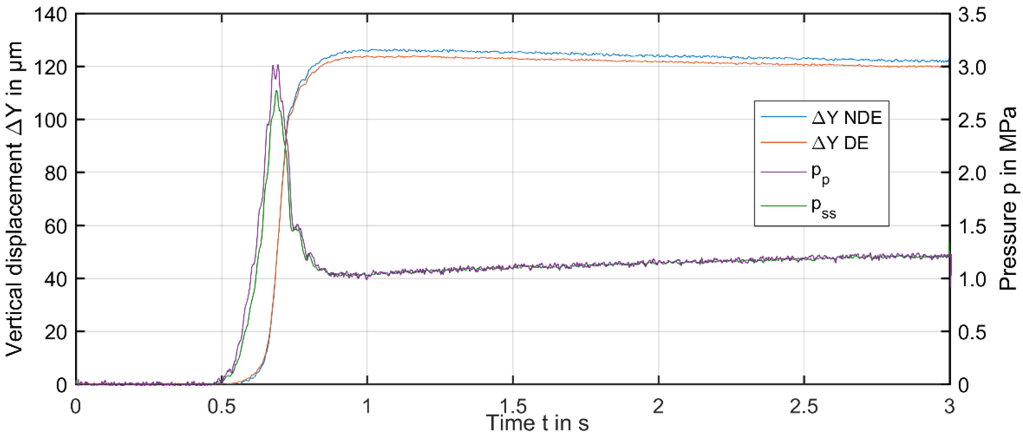
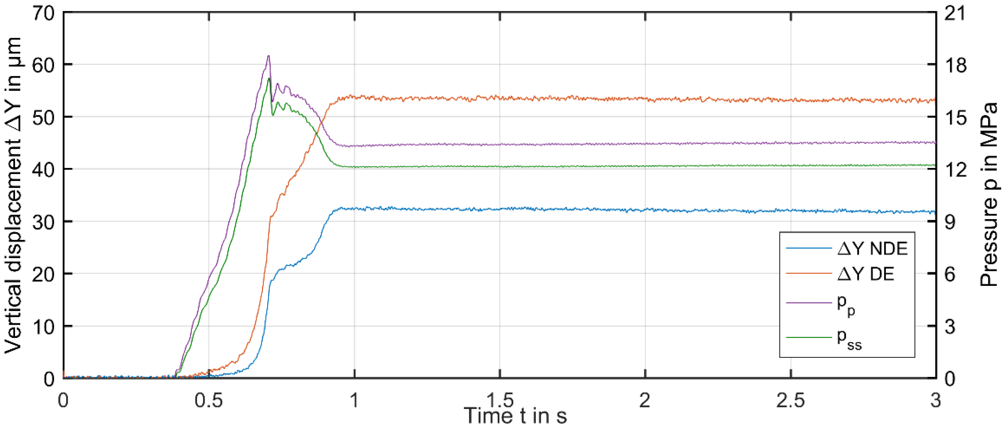
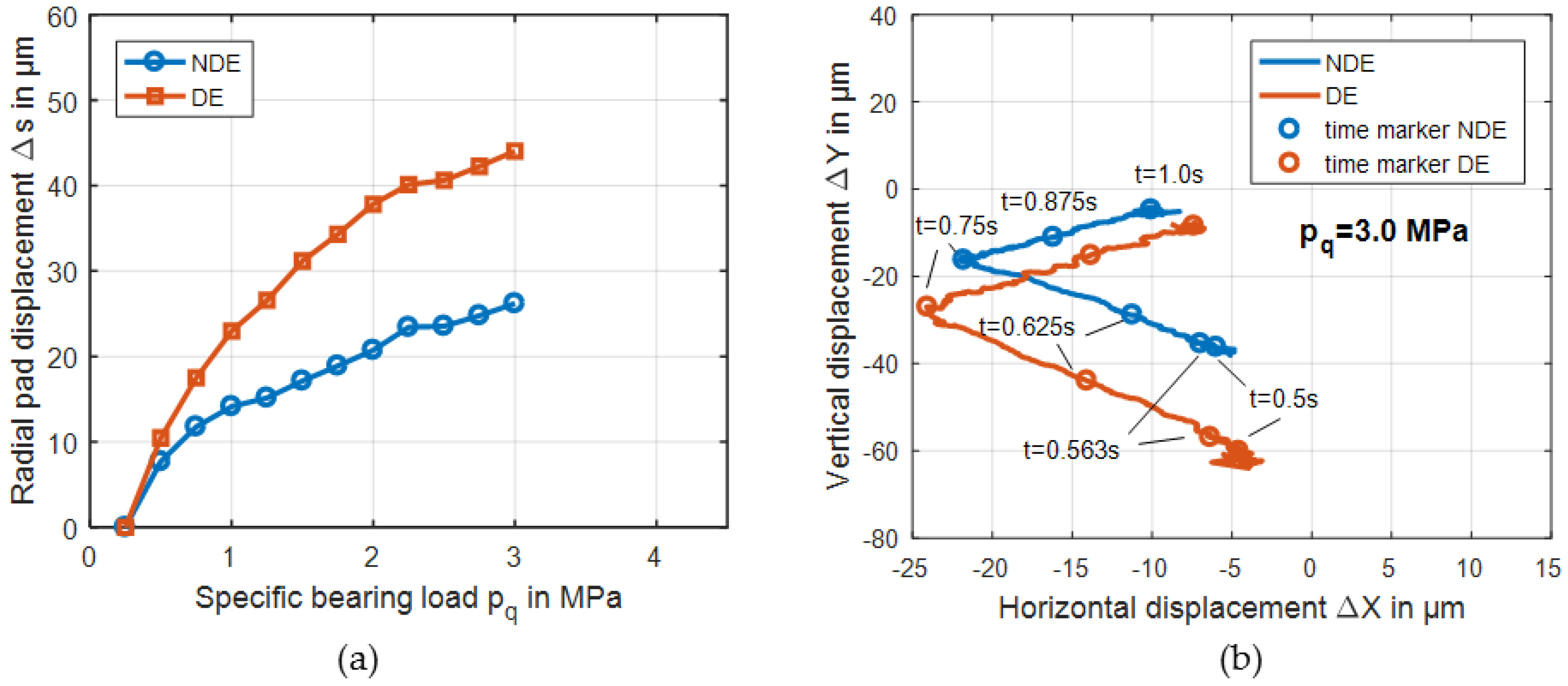
3.1.1. Dynamic Lift Procedure

Experimental investigations are conducted for the entire lift-off procedure for two different oil flow rates of 2.0 and 4.0 min−1 at specific mechanical bearings loads varying between 0.25 and 4.0 MPa.
Figure 5 shows proximity measurements relative to the initial state of displacement, which is reached with deactivated jacking-oil pockets due to applied static bearing load. Additionally, Figure 5 includes the pressure pp measured in the supply bore of the pocket and the one detected on the sliding surface close to the pocket pss according to the sensor position explained by Figure 3b. For this particular lift-off procedure, proximity probes prove that the bearing moves well aligned to the resting journal during lift-off as both sensors detect equal displacements at both axial bearing ends. A duration of approximately 2 s passes from maximum displacement in vertical direction until a stationary state is reached. Furthermore, the pressure measurement that exhibits the same time frame until its level remains constant proves this observed behavior. In addition to the time span presented in Figure 5, measurements with higher durations were conducted to confirm the point of time at which stationary conditions are present. As expected, the pressure sensor in the pocket shows slightly higher values than the one on the sliding surface. Comparing the time dependent characteristic of pressure and proximity measurement vertical movement of the bearing is first detected when the pressure reaches a value in the magnitude of the holding pressure obtained for stationary state after lift-off. In contrast to the previously described behavior, Figure 6 depicts a significant deviation between the displacement at the axial bearing ends during the lift-off procedure. Furthermore, vertical movement arises for pressures that are lower than the stationary holding pressure. These results can be referred to two major influences. First, Figure 7 clearly illustrates that the lift-off procedure exhibits a displacement behavior that is significantly asymmetric to the vertical layer but reproducible throughout the investigated load range. Moreover, the same characteristics of displacement are identified for the higher jacking-oil flow rates of 4.0 min−1. Consequently, the pressure in both jacking-oil pockets is different due to deviation in the hydraulic resistance of the lubricant gap. This behavior can be explained if the radial displacements of the pads are considered. To determine this parameter, the shift of the initial pad displacement due to applied vertical load is evaluated and shown in Figure 8a.
If this displacement between bearing and journal caused by increasing specific bearing load from 0.25 to 3.0 MPa before lift-off is considered, a modified displacement characteristic compared to the 3.0 MPa case in Figure 7 is identified due to pad elasticity and depicted in Figure 8b. Here, the initial conditions show a horizontal shift of the journal by approximately ΔX = 5 µm, and therefore, load on the left pad number 2 increases while it is reduced for pad number 3, which features the stator-sided pressure sensors. Secondly, the comparison of displacement measurements indicates that the differences of the displacement between the two bearing ends can be primarily attributed to axially varying pad elasticity. Misalignment between bearing housing and journal is significantly reduced after lift-off and nearly matches the one observed at a specific bearing load of pq = 0.25 MPa. Moreover, the following statements can be derived from Figure 8b:
  • With increasing load, the bearing housing moves close to the curve of maximum eccentricity among pad number 2 during the start of the lift-off procedure
  • The misalignment between bearing housing and journal changes its direction during the lift-off procedure
Measured pad elasticity for the investigated configuration is mainly related to the contact between journal and pad, and back of the pad and liner. Therefore, possible sources for the identified characteristic are entanglement between pad and liner, and more likely, errors in parallelism between sliding surface, back of the pad, liner, and bearing housing. The alignment between bearing housing and journal after lift-off is prove to be good.

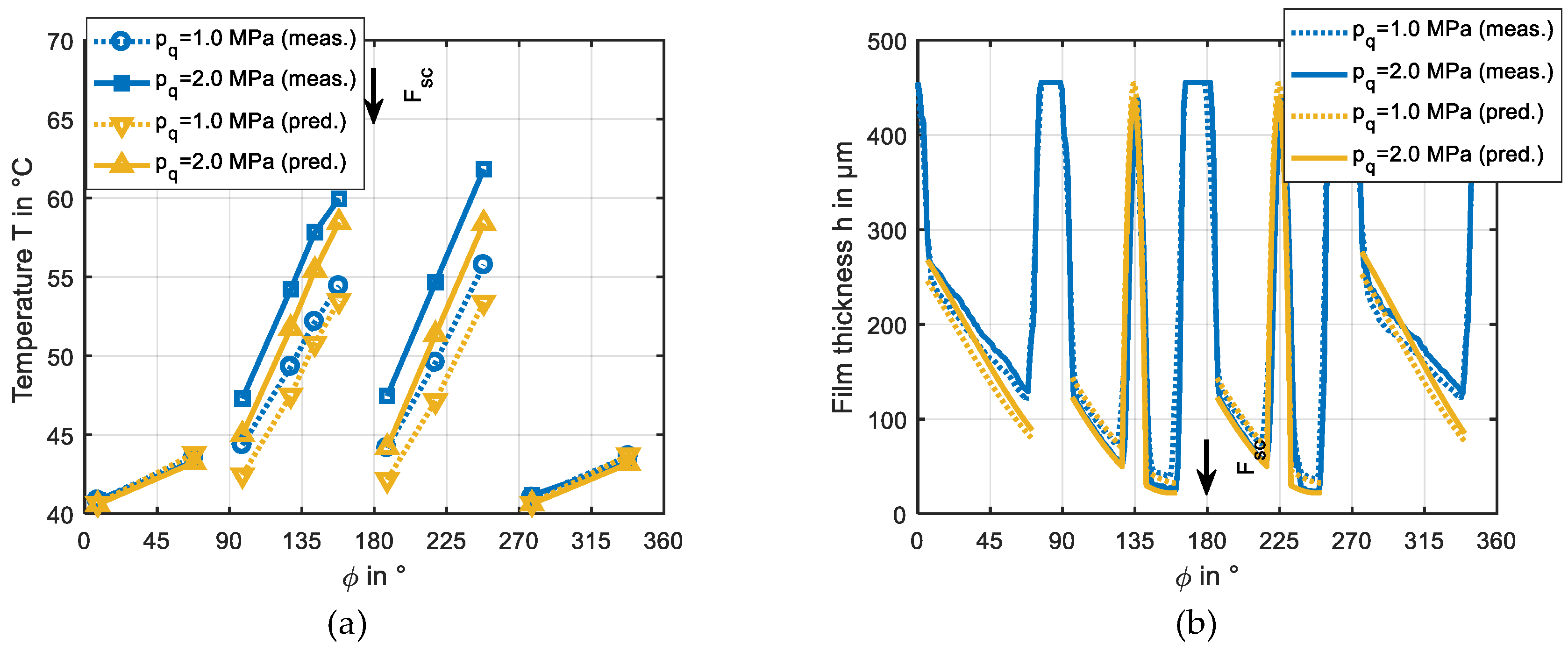
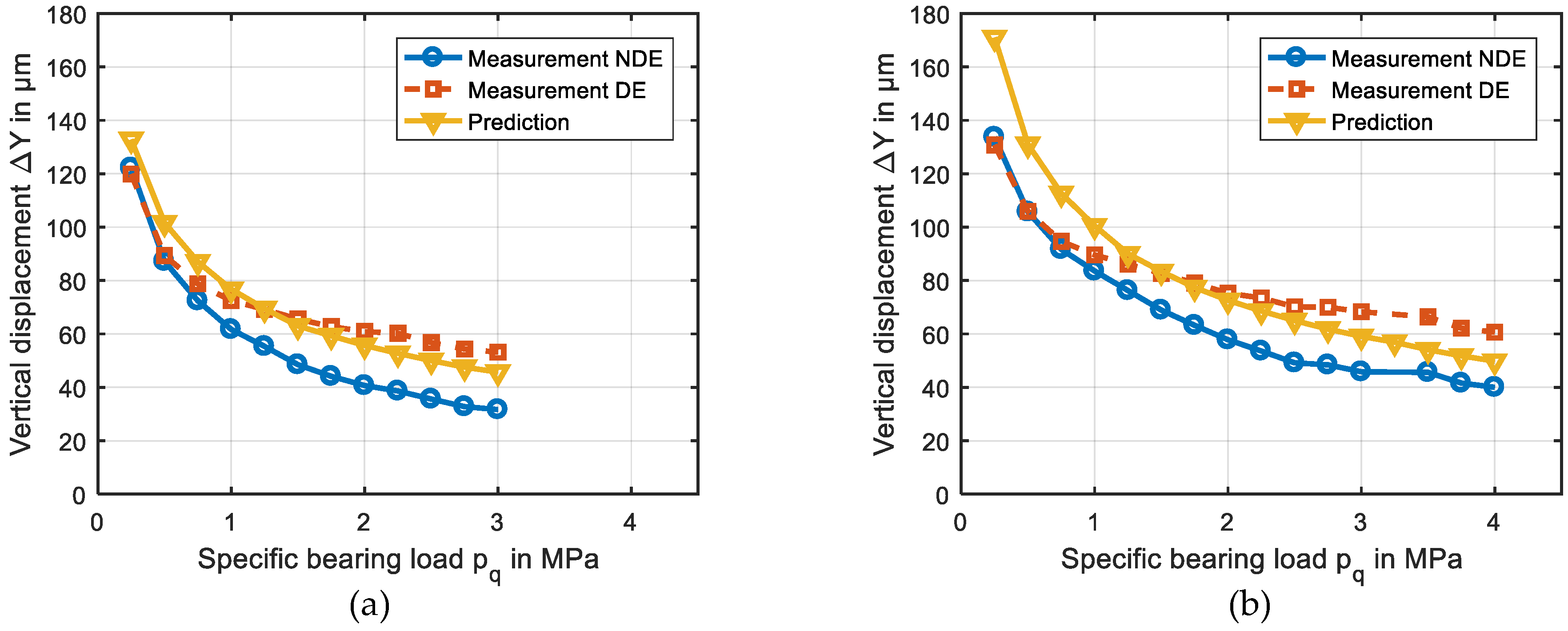
3.1.2. Stationary Characteristic Parameters of the Lift Procedure

The most important boundary condition that is required to design lift-off devices is the targeted lift displacement for a certain bearing load in order to ensure a sufficiently high minimum film thickness when the journal starts to rotate. This value and the bearing load define the configuration of the pump aggregate, which has to provide sufficient lift-off and holding pressure at certain oil flow rates. The lift-off pressure conforms to the maximum pocket pressure in order to ensure a successful lift procedure. In contrast to thrust bearings, the jacking-oil pockets of journal bearings can theoretically not be completely sealed by the shaft. Therefore, fluid film pressure on the sliding surface will always be present if jacking-oil is supplied, however, at much lower level than after lift-off as Figure 9 illustrates for the comparison between predicted pressure distributions of lift-off and holding conditions.
Although the lift-off pressure is of high practical relevance, there is no sharp definition of its determination. Here, a vertical displacement of ΔY = 2.0 µm is assumed in order to account for deformation of the Babbitt layer caused by pocket pressure. This displacement corresponds to a minimum film thickness of 1.4 µm located in the pivot region. Figure 10 shows good agreement between measured and predicted holding pressures for both investigated flow rates. However, deviations exist between the maximum measured pressure level and the predicted lift-off pressure, which can be related to the previously described characteristics of the entire lift-off procedure including the property that maximum pressures are expected on pad number 2.
While the flow rate does practically not influence the holding pressure level, it has an impact on the vertical displacement, which is decreasing with increasing bearing load according to Figure 11. For higher mechanical loads, the predicted values nearly match the average of the two displacements detected at both bearing ends. The vertical displacement for reduced bearing loads is overpredicted. In addition to the presented characteristic parameters, Figure 12 depicts the measured and predicted local film pressure and thickness distribution measured in the lateral middle plane of the bearing at a low rotational speed of 10 rpm. Measured and predicted data shows good agreement. The maximum pressure measured on the rotor side is slightly below the value detected by the stator-sided sensor in the pocket, which is included in Figure 10a,b. Furthermore, a slightly higher maximum pressure on pad number 3 is identified experimentally, while predictions provide nearly equal pocket pressures. This discrepancy is partly related to the previously explained geometrical and aligning errors. Moreover, remaining constraints and geometrical uncertainties in the entire experimental setup can support this behavior. The tilting angles of the upper unloaded pads are predefined and provide the same film thickness at the leading and trailing edge of the pad.

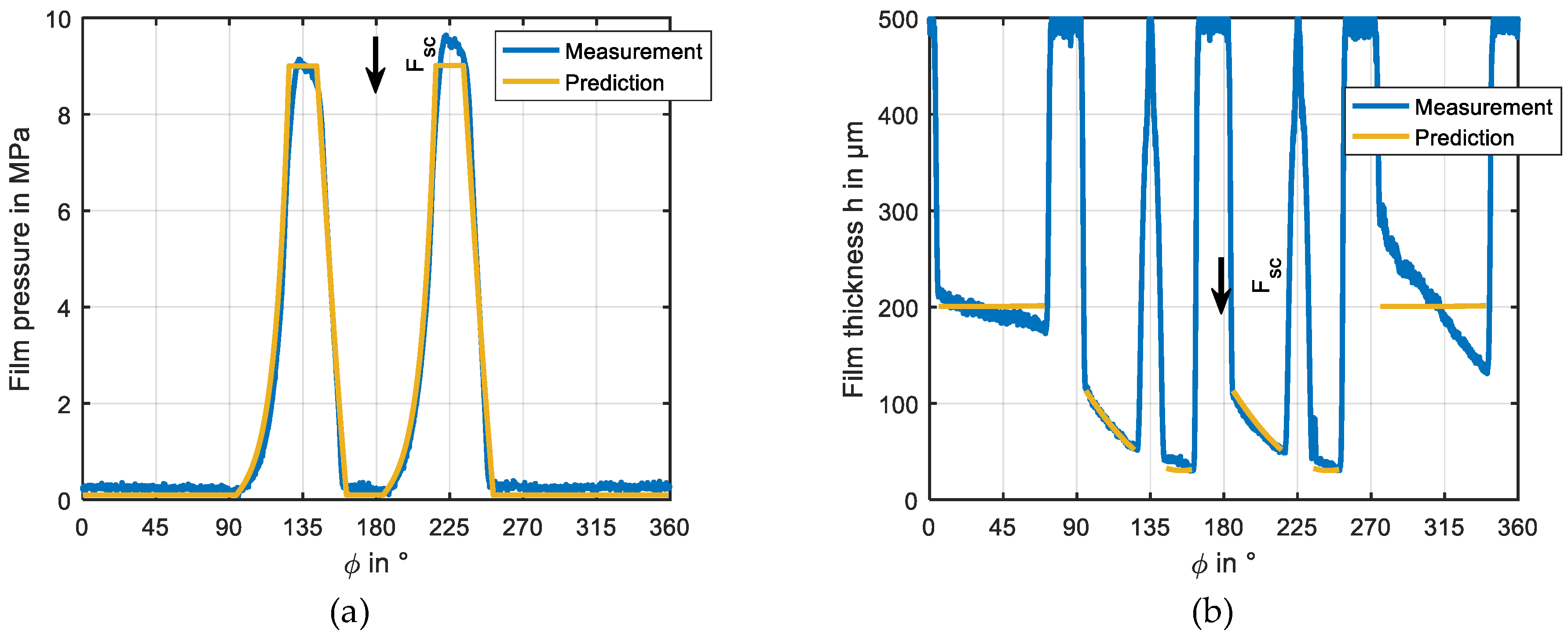
3.2. Hybrid Lubrication

Investigations of operation at hybrid lubrication providing a combined hydrostatic and hydrodynamic pressure are conducted for 10, 2000, and 3000 rpm. Figure 13 indicates that film pressure decreases with increasing journal speed while the minimum film thickness remains nearly constant within the investigated speed range. The latter result is in accordance with the one from Ref. [7]. The increase of film thickness from 2.0 to 2.5 MPa in Figure 13b was confirmed by repeating the measurement several times. Furthermore, experiments at 2000 rpm provided the same behavior too. This behavior might be related to a load dependent aligning processes within the bearing as no clear physical explanation for this behavior can be given based on hydrodynamic and hydrostatic lubrication theory. In addition to these results, Figure 14 shows generally good agreement of measured and predicted local film pressure and thickness distributions. Figure 14a depicts deviations of local pressures at the leading and trailing edge of the jacking-oil pockets on the highly loaded pads, which will be investigated in more detail for exclusive hydrodynamic operation in the subsequent chapter. While the film thicknesses in Figure 14b match excellently on the loaded pads, slight deviations exist on the upper pads. One reason for these differences is the deviation between the measured and predicted effective radial bearing clearance that can be determined as the mean of the film thickness values at the pivot positions. In the predictions an average radial pivot stiffness of 0.5 kN/µm is assumed based on the displacement measurements presented in Figure 8a.

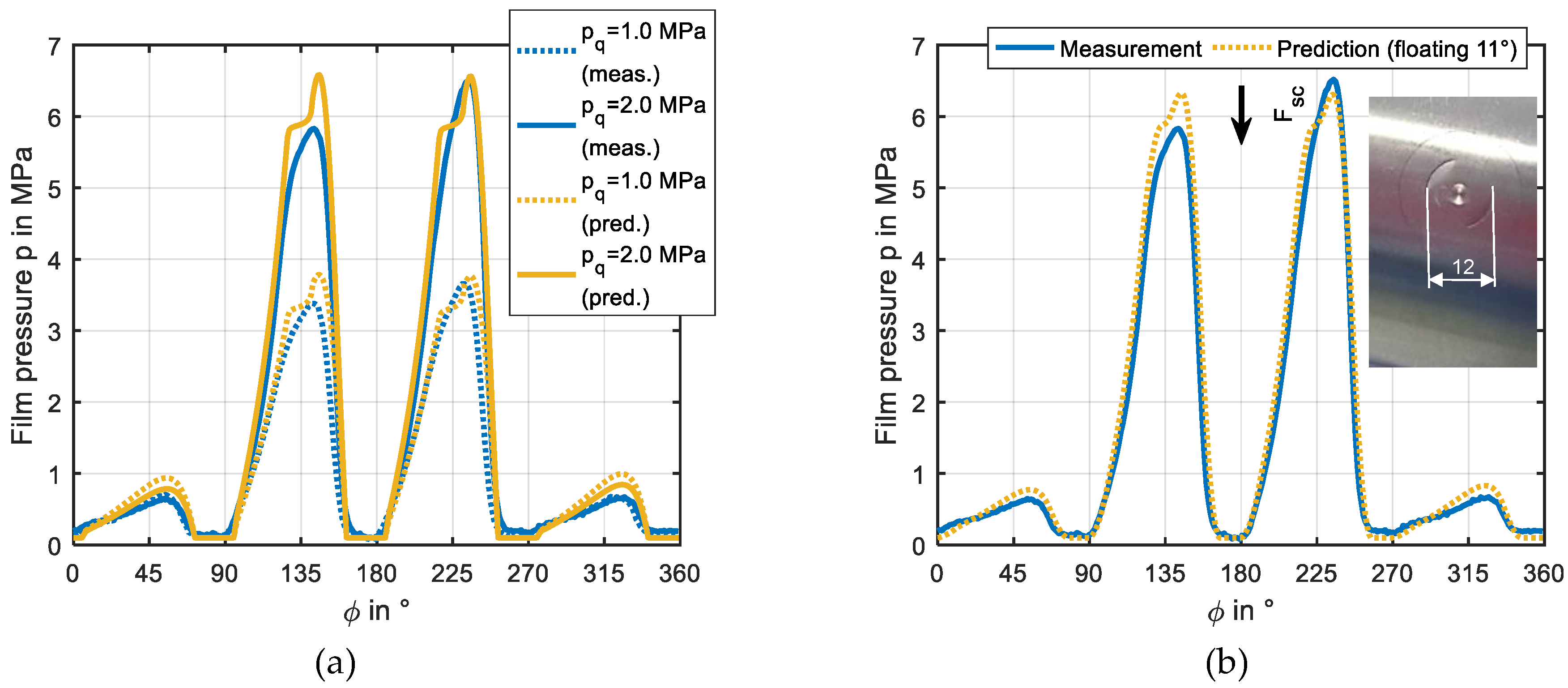
3.3. Operation in the Hydrodynamic Regime with Deactivated Jacking-Oil Pockets

Deactivated hydrostatic pockets disturb the shape of the sliding surface as an additional groove. To consider this impact within the predictions, the groove is modeled in the gap function used in the bearing code. Figure 15 depicts that temperature and film thickness distributions in the axial middle plane of bearing are predicted in good agreement with measurement data. However, slightly higher temperatures are obtained from simulation. Figure 16a provides a comparison of measured and predicted fluid film pressure distributions. While the pressure levels match well for both investigated bearing loads, the local characteristics of the pressure in the region of the jacking-oil pockets differ considerably. This result can be explained by the sensor geometry. The right side of Figure 16b shows a photography of the sensor and its mounting device, which has a diameter of approximately 12 mm. As the device does not smooth ideally to the journal surface, bypass flow occurs which equalizes the pressure level in this region. If the geometrical properties of the sensor are considered by a floating average value among its circumferential and lateral length, the predicted pressure characteristic gets closer to the measured one as illustrated in Figure 16b.
The comparison of hydrodynamic and hybrid lubrication in Figure 17a exhibits slightly higher maximum pressure levels for hybrid lubrication if mechanical load increases. Simultaneously, the minimum film thickness rises significantly. According to Figure 17b measured minimum film thickness at a journal speed of 3000 rpm and a specific bearing load of 2.0 MPa increases by approximately 7 µm while the predicted values rise by nearly 10 µm.

4. Discussion and Conclusions

Experimental and theoretical results for the impact of activated and deactivated jacking-oil pockets are presented from start-up to surface speeds of 20 m/s. For the lift procedure at zero journal rotation good correspondence between measured and predicted holding pressures is obtained, while experimentally determined maximum pressure values show a significantly lower level than theoretically established lift-off pressures. This behavior can be attributed to considerable disturbance of symmetric conditions, which are identified by displacement measurements between journal and bearing housing. Increasing mechanical loads at zero jacking-oil flow prove horizontally and in particular vertically non-symmetric displacements between journal and bearing housing. Measurement results for the dynamic lift procedure indicate that the entire process is sensitive to this influence especially before lift-off is achieved. Mean vertical displacements are overpredicted for low mechanical loads while good correspondence with measured results exists for the range of practical relevant loads from 2.0 to 4.0 MPa.
In accordance with the theoretical results of other researchers, the impact of the rotor speed on the measured and predicted minimum film thickness at hybrid lubrication with journal rotation at activated jacking-oil pockets is low in the investigated speed range. On the contrary, maximum pressure rises considerably with decreasing speed. If the lift-oil system is switched off and the check valve in the pad is closed, hydrodynamic lubrication is influenced by the disturbance of the sliding surface based on the shape of the jacking-oil pocket. The predicted impact of the pocket geometry on the local pressure distribution could not be proved experimentally. However, geometrical properties of the pressure measurement device on the journal surface explain an essential part of the observed discrepancies. Beside the previously described deviations, good correlation between measurement and prediction was obtained for all three investigated lubrication conditions regarding characteristic parameters as well as local distributions.
Experimental results indicate that the characteristic of the dynamic lift procedure is very sensitive to disturbance of symmetry. As a consequence, the lift-off pressure, which is a design parameter for the jacking-oil pump device, could not be determined reliably by the applied experimental set-up in these investigations.

Author Contributions

P.P. adjusted the test rig for the presented investigations and conducted all experiments. T.H. conducted simulations, evaluated the entire results and wrote the paper. H.S. supervised the project and added contributions by several discussions.

Funding

This research was funded by the German Federal Ministry of Economic Affairs and Energy. The financial support was assigned by the Industrial Research Association (AiF e. V.) in project number IGF 17173 N/1.

Acknowledgments

The authors thank the expert committees of the German research communities FVA e. V. and FVV e. V. for the technical and scientific steering of this research project.

Conflicts of Interest

The authors declare no conflict of interest.

Nomenclature

Bbearing length
clubricant specific heat
Dnominal bearing diameter
F0, F1, F2viscosity factors
Fscstatic bearing load
hfilm thickness
nrotor speed
ppressure
pppocket pressure
p q specific bearing load p q = F sc / ( B · D )
psspressure on sliding surface at sensor position
Qjojacking-oil flow rate
u, v, wflow velocities
x, y, zcartesian coordinates
Θlubricant density ratio
ηlubricant dynamic viscosity
λlubricant conductivity
ρlubricant density
φangular coordinate
Φdissipation

References

  1. Neale, M.J. The Tribology Handbook; Butterworth-Heinemann: Oxford, UK, 1995. [Google Scholar]
  2. Fillon, M.; Wodtke, M.; Wasilczuk, M. Effect of presence of lifting pocket on the THD performance of a large tilting-pad thrust bearing. Friction 2015, 3, 266–274. [Google Scholar] [CrossRef] [Green Version]
  3. Chaomleffel, J.P.; Nicolas, D. Experimental investigation of hybrid journal bearings. Tribol. Int. 1986, 19, 253–259. [Google Scholar] [CrossRef]
  4. Varela, A.C.; Santos, I.F. Performance improvement of tilting-pad journal bearings by means of controllable lubrication. Mech. Ind. 2012, 13, 17–32. [Google Scholar] [CrossRef]
  5. Varela, A.C.; Santos, I.F. Dynamic coefficients of a tilting pad with active lubrication: Comparison between theoretical and experimental results. ASME J. Tribol. 2015. [CrossRef]
  6. Elwell, R.C. Hydrostatic lubrication. In Handbook of Tribology; Booser, E.R., Ed.; CRC Press: Boca Raton, FL, USA, 1984. [Google Scholar]
  7. Raud, X.; Fillon, M.; Helene, M. Numerical modelling of hydrostatic lift pockets in hydrodynamic journal bearings–Application to low speed working conditions of highly loaded tilting pad journal bearings. Mech. Ind. 2013, 14, 327–334. [Google Scholar] [CrossRef]
  8. Buchhorn, N.; Kukla, S.; Bender, B.; Neumann, M. Tilting-pad journal bearing in hybrid operation: A numerical and experimental investigation. In Proceedings of the 63rd ASME Turbo Expo, Oslo, Norway, 11–15 June 2018. [Google Scholar]
  9. Kluitenberg, M.; Childs, D. Measuring the impact of jacking-oil ports on the rotordynamic characteristics of a four-pad, LBP, tilting-pad journal bearing. In Proceedings of the 1st Global Power and Propulsion Forum, Zurich, Switzerland, 16–18 January 2017. No. GPPF-2017-175. [Google Scholar]
  10. Tschoepe, D.P.; Childs, D.W. Measurements versus predictions for the static and dynamic characteristics of a four-pad, rocker-pivot, tilting-pad journal bearing. ASME J. Eng. Gas Turb. Power 2014. [Google Scholar] [CrossRef]
  11. Hagemann, T.; Kukla, S.; Schwarze, H. Measurement and prediction of the static operating conditions of a large turbine tilting-pad bearing under high circumferential speeds and heavy loads. In Proceedings of the 58th ASME Turbo Expo, San Antonio, TX, USA, 3–7 June 2013. [Google Scholar]
  12. Kukla, S.; Hagemann, T.; Schwarze, H. Measurement and prediction of the dynamic characteristics of a large turbine tilting-pad bearing under high circumferential speeds. In Proceedings of the 58th ASME Turbo Expo, San Antonio, TX, USA, 3–7 June 2013. [Google Scholar]
  13. Hagemann, T. Ölzuführungseinfluss Bei Schnell Laufenden und Hoch Belasteten Radialgleitlagern unter Berücksichtigung des Lagerdeformationsverhaltens. Ph.D. Thesis, Clausthal University of Technology, Clausthal-Zellerfeld, Germany, 2011. [Google Scholar]
  14. Hagemann, T.; Schwarze, H. A model for oil flow and fluid temperature inlet mixing in hydrodynamic journal bearings. ASME J. Tribol. 2018. [Google Scholar] [CrossRef]
  15. Dowson, D. A Generalized Reynolds Equation for Fluid Film Lubrication. Int. J. Mech. Sci. 1962, 4, 159–170. [Google Scholar] [CrossRef]
  16. Hagemann, T.; Blumenthal, H.; Kraft, C.; Schwarze, H. A study on energetic and hydraulic interaction of combined journal and thrust bearings. In Proceedings of the 60th ASME Turbo Expo, Montreal, QC, Canada, 15–19 June 2015. [Google Scholar]
  17. Hagemann, T.; Schwarze, H. Theoretical and experimental analyses of directly lubricated tilting-pad journal bearings with leading edge groove. ASME J. Eng. Gas Turb. Power 2018. [Google Scholar] [CrossRef]
  18. Hagemann, T.; Zeh, C.; Prölß, M.; Schwarze, H. The impact of convective fluid inertia forces on operation of tilting-pad journal bearings. Int. J. Rotat. Mach. 2017. [Google Scholar] [CrossRef]
  19. Bou-Said, B.; Chaomleffel, J.P. Hybrid Journal Bearings: Theoretical and Experimental Results. ASME J. Tribol. 1989, 111, 265–269. [Google Scholar] [CrossRef]
  20. Hagemann, T.; Kraft, C.; Pfeiffer, P.; Schwarze, H. Erhöhung der Betriebssicherheit von Rotierenden Maschinen deren Hydrodynamische Radial- und Axiallager Zusätzlich mit einer Hydrostatischen Laufhilfe Ausgestattet sind; Technical Report 1135; FVV: Frankfurt am Main, Germany, August 2017. [Google Scholar]
Figure 1. (a) Test section of the test rig, (b) modified test shaft with rolling element support bearings.
Lubricants 06 00081 g001
Figure 2. (a) Modified drive unit with gear belt, (b) test shaft with mounted pinion.
Lubricants 06 00081 g002
Figure 3. (a) Initial test bearing with red signed thermocouple positions, (b) modified pads with jacking-oil pockets.
Lubricants 06 00081 g003
Figure 4. Measurement of displacement between journal and bearing by proximity probes.
Lubricants 06 00081 g004
Figure 5. Measured pressure and vertical displacement during lift procedure (pq = 0.25 MPa, Qjo = 2.0 min−1).
Lubricants 06 00081 g005
Figure 6. Measured pressure and vertical displacement during lift procedure (pq = 3.0 MPa, Qjo = 2.0 min−1).
Lubricants 06 00081 g006
Figure 7. Measured displacement at both bearing ends during lift procedure (Qjo = 2.0 min−1).
Lubricants 06 00081 g007
Figure 8. (a) Measured radial pad displacement of the pad, (b) displacement at both bearing ends during lift procedure including pad displacement (Qjo = 2.0 min−1, pq = 3.0 MPa).
Lubricants 06 00081 g008
Figure 9. Predicted pressure distribution at start of lift-off (a) and at holding conditions (b) (Qjo = 2.0 min−1, pq = 3.0 MPa).
Lubricants 06 00081 g009
Figure 10. Measured and predicted pocket pressures ((a) Qjo = 2.0 min−1, (b) Qjo = variable).
Lubricants 06 00081 g010
Figure 11. Measured and predicted vertical displacement ((a) Qjo = 2.0 min−1, (b) Qjo = 4.0 min−1).
Lubricants 06 00081 g011
Figure 12. Measured and predicted film pressure (a) and film thickness (b) in the axial middle plane of the bearing (n = 10 rpm, Qjo = 2.0 min−1, pq = 2.0 MPa).
Lubricants 06 00081 g012
Figure 13. Measured and predicted maximum pressures (a) and minimum film thickness (b) (Qjo = 2.0 min−1).
Lubricants 06 00081 g013
Figure 14. Measured and predicted film pressure (a) and film thickness (b) in the axial middle plane of the bearing (n = 3000 rpm, Qjo = 2.0 min−1).
Lubricants 06 00081 g014
Figure 15. Measured and predicted local pad temperatures (a) and film thickness (b) in the axial middle plane of the bearing (n = 3000 rpm).
Lubricants 06 00081 g015
Figure 16. Measured and predicted local film pressure in the axial middle plane of the bearing (n = 3000 rpm, (a) pq = variable, (b) pq = 2.0 MPa).
Lubricants 06 00081 g016
Figure 17. Measured and predicted maximum pressures (a) and minimum film thickness (b) at hydrodynamic and hybrid lubrication (Qjo = 2.0 min−1).
Lubricants 06 00081 g017
Table 1. Test bearing parameters.
ParameterValue
Geometrical Properties
Number of tilting-pads4
Nominal diameter, mm120
Tilting-pad thickness, mm20
Bearing width, mm72
Angular length of tilting-pads, degrees70
Relative position of tilting-pad support0.6
Radial clearance (assembled), µm108
Preload (assembled)0.50
Angular length of jacking-oil pockets, degree16
Width of jacking-oil pockets, mm20
Maximum depth of jacking-oil pockets, mm0.4
Static Analysis Parameters
Bearing load, kN2.2–34.6
Rotational speed, rpm0–3000
Lubricant supply temperature, °C50
Lube oil flow rate, l/s1.0
Lubricant Properties
LubricantISO VG 32
Lubricant density kg/m³865 @ 40 °C
Lubricant specific heat capacity kJ/(kg·K)2.0 @ 20 °C
Thermal Boundaries and Material Properties
Lubricant thermal conductivity, W/(m·K)0.13
Pad and journal thermal conductivity, W/(m·K)45
Pad ambient temperature, °C60

