Scratching Cu|Au Nanolaminates


1
Department of Microsystems Engineering, University of Freiburg, Georges-Köhler-Allee 103, 79110 Freiburg, Germany
2
Institute for Applied Materials, Karlsruhe Institute of Technology, Straße am Forum 4, 76131 Karlsruhe, Germany
3
Freiburg Materials Research Center, University of Freiburg, 79104 Freiburg, Germany
4
Cluster of Excellence livMatS @ FIT—Freiburg Center for Interactive Materials and Bioinspired Technologies, University of Freiburg, Georges-Köhler-Allee 105, 79110 Freiburg, Germany
*
Author to whom correspondence should be addressed.
Lubricants 2019, 7(5), 44; https://doi.org/10.3390/lubricants7050044
Submission received: 15 March 2019
/
Revised: 3 May 2019
/
Accepted: 13 May 2019
/
Published: 21 May 2019
(This article belongs to the Special Issue Friction Mechanisms)
Abstract
:We used molecular dynamics simulations to study the scratching of Cu|Au nanolaminates of 5 nm layer thickness with a nanoscale indenter of 15 nm radius at normal forces between N and N. Our simulations show that Au layers wear quickly while Cu layers are more resistant to wear. Plowing was accompanied by the roughening of the Cu|Au heterointerface that lead to the folding of the nanolaminate structure at the edge of the wear track. Our explorative simulations hint at the complex deformation processes occurring in nanolaminates under tribological load.
1. Introduction
The “hardness” of a surface is determined through indentation experiments, which measure the force required for a macroscopic or microscopic indenter to penetrate a surface [1]. The same instruments are often used to test the scratch resistance of surfaces and thereby a means of studying structural transformation of materials [2] or flow patterns [3,4,5] under normal force and shear. A related technique, atomic-force microscopy (AFM), uses much smaller tips (on the order of ∼10 nm radius) and can be used to characterize the frictional properties of surfaces [6,7] but it is rarely used to probe surfaces in the plastic regime [8,9,10]. Yet, using the AFM to probe surfaces offers the possibility to map local variations in hardness [11,12] and study the intrinsic strength of materials since the deformed volume under an AFM indenter is small and often defect-free [13]. Plastic deformation is also responsible for part of the material loss during abrasive, sliding wear [8,14,15,16] and the plowing motion of asperities on the counter body contributes to the friction between two materials [16,17]. It has been noted that in metals the relationship between grain-size and indenter radius is important and that the friction force depends on hardness only for grain sizes smaller than the indenter [18].
We here use molecular dynamics (MD) simulations to study scratching of a specific class of materials that are nanostructured by design and therefore have an intrinsic scale that is on the order of the radius of an AFM tip. Metallic nanolaminates, often also called heterostructures or multilayers, consist of layers of pure metals or alloys of alternating composition and structure [19,20] that are typically grown in sputter deposition processes. In bulk composites, mechanical properties can often be obtained from rules of mixture but this simple description no longer holds for nanolaminates. The nanolaminates’ exceptional properties can be connected to two associated factors, the reduction in layer thickness to the intrinsic scales of dislocations, such as the Burgers vector or the splitting distance of Shockley partials and the importance of interfaces in the system [21]. These metallic nanolaminates not only exhibit enhanced strength and hardness [20,22,23,24,25], wear resistance [26,27] or toughness [28] but also offer the possibility to tailor those properties by choosing material combinations [29]. Metallic nanolaminates have been characterized using indentation [3,4] and scratch [5] experiments but not yet using tips of nanometer size.
2. Methods
Our atomistic model for the Cu|Au nanolaminate system consists of 8 layers of 5 nm thickness bringing the overall thickness to approximately 40 nm. Cu and Au are stacked with their surfaces and the topmost layer exposes a free Au surface. Cu and Au have the same crystal orientation. The total system is composed of approximately 20 million atoms. The lateral cell size needs to be commensurate with the lattice constant of both, Au (lattice constant Å) and Cu ( Å), phases. The nominal misfit between the two phases and the residual misfit between two crystalline supercells can be defined as [30]
where n and m are the numbers of unit cells of the Au and Cu supercells that constitute the individual layers in the multilayer stack. Our choice of simulation cell size minimizes while keeping the overall size small enough for our simulation methods. The size of the final system is 130 and 390 unit cells or 145 and 438 unit cells along the x- and y-directions, respectively. The lateral size of the system is 65 nm along the x-direction and 113 nm along the y-direction. Sliding takes place in the y-direction and both x- and y-directions are treated periodic. Figure 1 shows a snapshot of the system.
Since Cu and Au are miscible (and can even form stable binary phases) [31,32,33], the interface between Cu and Au were slightly intermixed to mimic interdiffusion observed in high-resolution microscopy of these multilayers [3]. In brief, the ideal concentration profile for Fickian diffusion between the two miscible species was computed. Cu and Au atoms were then randomly swapped such that this profile is reproduced on average; more details are given in Reference [34]. Note that this adds friction between the layers; a perfect Cu|Au heterointerface shows almost negligible friction because it forms a perfect triangular lattice of Shockley partial dislocations at the interface [35]. A few atomic layers are kept fixed at the bottom of the simulation box to act as a rigid substrate and anchor the atomistic model in space.
We modeled the indenter by a rigid sphere of 30 nm diameter. This diameter is typical for tips used in classic atomic-force microscopy (AFM) type experiments [36,37]. AFM tips are also considered as models for a single asperity on a rough surface [7]. The indenter was obtained by freezing the structure of a Cu50Zr50 metallic glass obtained by melting a random solid solution of Cu50Zr50 at 2500 K and then quenching it down to 0 K at a rate of 6 K ps. A purely repulsive (cut-off radius ) Lennard-Jones potential acted between atoms in the nanolaminate slab and the indenter. The interaction parameters with Cu and Au are , , , [38]. Compared with a perfectly smooth mathematical representation of a hemisphere, the amorphous structure introduced finite friction between indenter and metallic surface and gives rise to realistic stress fluctuations at the contacting interface [13,39]. The rationale behind this model is that nearly all experimental tips will have some some sort of surface disorder: AFM tips are commonly made out of Silicon which oxidizes to amorphous silica at ambient conditions [37]. Note that this interaction model ignores adhesion between tip and substrate.
We used an embedded atom method potential for the simulation of the binary Cu-Au system. The potential is based on two high-quality potentials for the pure Cu and Au phases [40,41]. These potentials in particular describe well the stacking fault energy that is crucial for the proper description of mechanical properties of our structures. Since all binary Cu-Au potentials underestimate the stacking fault energy by around an order of magnitude, we tailored the cross-potential to the properties of the Cu3Au, CuAu and CuAu3 phases. A detailed description of the potential and its properties can be found in Reference [42].
Our simulations were run at constant temperature (300 K) using a Langevin thermostat with a damping constant of 10 ps acting on the bottom two laminate layers of the system. The calculations were performed in two steps. The first step consisted in lowering the spherical indenter along axis. The indenter was lowered with a downward velocity of Å ps (=15 m s) until the force acting on the rigid indenter atoms reached the targeted value. We ran four sets of calculations at 300, 620, 1000 and 1800 eV Å (≈0.48, , and N). Then the indenter was moved along the sliding direction over a distance of 40 nm from the indentation point. The calculations were run at a constant sliding velocity of Å ps (=50 m s). Since the tip model in our simulation was a spherical shell and represents just the bottom part of a true AFM tip, the mass of the sliding indenter was artificially increased by a factor of 50. The tip moved at constant velocity and the direction of movement was instantaneously reversed upon reaching the dead centers. We performed a maximum of 5 reciprocating passes. The stroke length of 40 nm required 1.6 ns of simulation time for a single reciprocating cycle.
The simulations were post-processed using two techniques. First, we analyzed the defect structure introduced by the plastic deformation using the adaptive common neighbor analysis (CNA) [43,44,45]. This allows us to count and classify the dislocations present in the system. Second, in order to quantify plastic rearrangements rather than defects (that are the carriers of plasticity by may disappear at sinks), we computed the local strain tensor from the analysis of Falk & Langer within local neighbor spheres of radius Å that includes just an atom’s nearest neighbors [46]. More precisely, we compute the local deformation gradient tensor for each atom from the displacements of each atom’s neighbors between two consecutive snapshots. From the deformation gradient we then obtained the Green-Lagrangian strain tensor for atom i [47], . Finally, we computed the von-Mises invariant of . This allows us to visualize the total amount of deformation experienced by the layers.
3. Results
Figure 1 shows the initial structure of the simulation setup. The system was composed of several flat Cu|Au layers and terminated by an Au layer on top. The system was defect-free except for the defects introduced by intermixing the Cu|Au layers at the interfaces. Individual panels in Figure 2 show the qualitative evolution of the system at the different calculation stages at a normal force of 1000 eV Å.
During indentation (Figure 2b), the indenter created a depression in the soft uppermost Au layer but did not penetrate all the way to the next Cu layer. The indenter penetrated to a depth of 1.4 nm at a normal force of 300 eV Å and to a depth of 2.5 nm at a normal force of 620 eV Å. The latter depth is approximately half way through the first Au layer. At 1000 eV Å, the identation depth (around 4 nm) reached the first interfacial zone where Cu and Au are intermixed. These initial indentation depths are the leftmost points of the data shown in Figure 3, that is the depth from which we start cyclic sliding. At a normal force of 1800 eV Å, the indenter completely sank through the first Au layer during initial indentation. During subsequent cycling, the indenter penetrated all layers up to the bottom boundary of the simulation cell within the first cycle, indicating that the load exceeded the hardness of the composite material. In the following, we will therefore focus on describing the results obtained at 300, 620 and 1000 eV Å normal force where we observe steady sliding and continuous wear.
After indentation (Figure 2b), we moved the indenter laterally at a constant velocity of 0.5 Å ps in a reciprocating motion. During this displacement the normal force was held constant. The true force acting on the indenter comprises a component from the inertia of the tip and varies around the target value. The fluctuation is on the order of ±10 eV Å at a normal force of 300 eV Å, ±19 eV Å at a normal force of 620 eV Å and ±23 eV Å at a normal force of 1000 eV Å (Figure 4a). The lateral forces necessary to displace the indenter are shown in Figure 4b. The reversal of the sliding direction was accompanied by a reversal of the sign of the force and a corresponding jump. Except for the lowest normal force investigated here (300 eV Å), the absolute value of the force jumped to a lower value as the sliding direction was reversed. At 1000 eV Å, it is clearly visible in Figure 4b that the force increased monotonously with sliding distance for all individual strokes, that is, the system shows what is sometimes denoted as “frictional strenghtening”. A similar increase is visible during the initial cycles at 620 eV Å, yet it appears that the system “runs in” and the friction response remains constants and reproducible during the later cycles. We observe no such frictional strengthening at 300 eV Å. Another notable feature in the two cases at higher normal force is that during cycles 2 to 5, the rate a which the lateral force strengthened increased as the indenter approached the dead centers. (See the kink indicated denoted “(3)” in Figure 4b.)
Figure 4c, panels (1) and (2), show snapshots of the reverse stroke at two different stages during frictional strengthening for the most pronounced case at 1000 eV Å. (Figure 4b indicates where in the friction loop those snapshots were taken.) The snapshots clearly show that material is pushed by the indenter in the sliding direction. As the indenter approaches the point of reversal (Figure 4c (3) and (4)), this material is pushed into the pile up near the dead ends.
The progression in geometry at a normal force of 1000 eV Å after each subsequent sliding cycle is shown in Figure 2c–f. The indenter progressively sank into the substrate, accompanied by transfer of material to the edge of the wear track where it piled up. Figure 2 and Figure 3 also shows that the indenter sank quickly into an Au layer while it requires multiple cycles to break through the harder Cu layer. At a normal force of 620 eV Å the indenter tip barely reached the pure Cu layer after 5 cycles and the penetration rate was hence significantly reduced over the case at the larger normal force. At a normal force of 300 eV Å the indenter tip barely reached a depth corresponding to half the thickness of the first Au layer. Note that in Figure 2d both the terminating Cu and the Au layer underneath had thinned, indicating transport of material out of the contact by the reciprocating motion. Besides thinning of the softer Au layer, the heterointerface developed roughness. This is especially visible in Figure 2c–e for the heterointerface right under the sliding tip. Roughening is also observed outside of the wear track just below the material piled up by the motion of the tip.
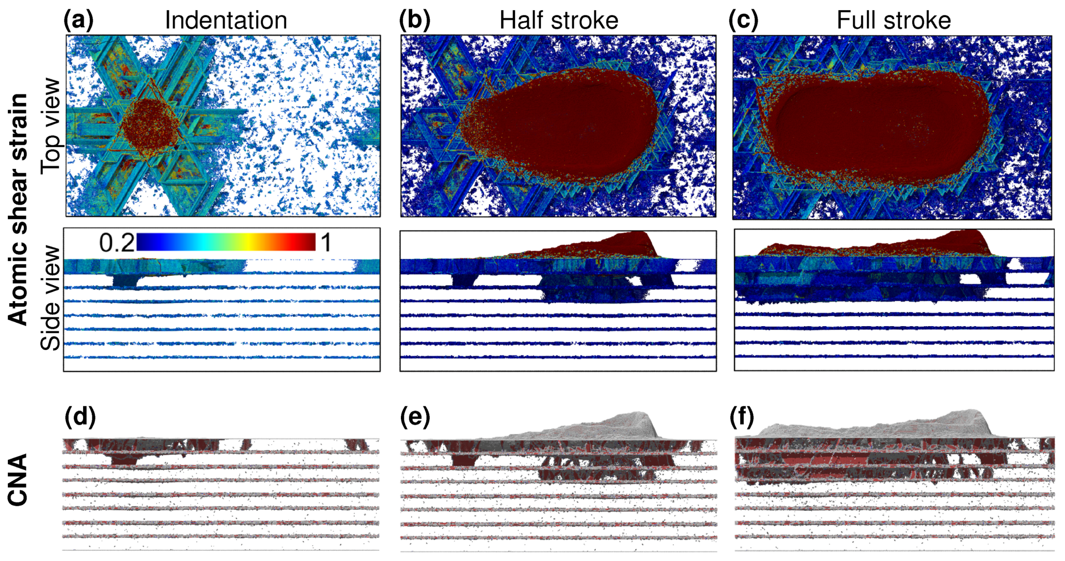
We show details of the deformation process in Figure 5 for the simulation at a normal force of 1000 eV Å. Panels (a)–(c) show the strain accumulated for each atom. We hide atoms that had experienced less than 20% of atomic strain. During indentation, the strain is localized within the terminating Au layer and a small region beneath the indenter apex. We complemented this strain analysis by a common neighbor analysis (CNA) that reveals the defect structure. (The supplementary material contains videos of the CNA analysis of all three simulations described here.) Figure 5d shows stacking faults in the heavily strained region, demonstrating that the deformation of the material is accompanied by the formation of stable defects. The top view of the deformation during indentation reflects the threefold symmetry of the slip planes outside of the main indenter depression. Dislocations nucleated underneath the indenter apex and then escaped on the respective FCC slip planes leading to a region with six-fold symmetry that carries most of the deformation.
The strain accumulated in the first layer and the corresponding density of defects (Figure 5d–f) increased after the first stroke. Interestingly, damage in the lower-lying Cu layer (and the next Au layer) can only be seen at the location of indentation and the opposite end of the wear track. After the first full stroke, deformation and defect structure had spread from the terminating Au layer to the next Cu and the following Au layer (Figure 5f). At this point the indenter had started to penetrated the harder Cu layer (Figure 2c). The softer Au layer beneath then directly accommodated some of the deformation introduced into the layer (Inset of Figure 3).
4. Discussion
We first discuss the results obtained for a normal force of 1000 eV Å. During the initial indentation (Figure 2a and Figure 3) the indenter did not penetrate entirely the first Au layer. Figure 5d shows a significant density of stacking faults right underneath the indenter. As expected by various models such as the Hall-Petch or confined layer slip (CLS) [48,49,50], at such a small scales the interface plays a critical role blocking dislocations, since there is no space for dislocations to pile up. The accumulation of defects is therefore responsible for the hardening of the single crystal Au layer, allowing the indenter to only penetrate a fraction of its depth. The sudden increase in indentation depth at the onset of sliding, marked by an arrow in Figure 3, can be explained by a sudden burst of dislocation activity in the third layer while the indenter remains above the first interface. The burst of dislocations and therefore plastic deformation is clearly captured by the atomic strain analysis shown in the inset of Figure 3. During the whole indentation process, part of the dislocations leave the contacting regions as prismatic half-loops parallel to the surface, leading to sixfold symmetric deformation patterns (Figure 5a). Identical patterns have been observed in experiments [51,52], discrete dislocation dynamics [53] and molecular dynamics simulations [13].
The frictional strengthening observed in Figure 4b can be rationalized by the indenter displacing material into the sliding direction as shown in Figure 4c ((1)–(3)). The pile-up of material in front of the indenter facilitates flow of material towards the ends of the wear track. This happens because the pile-up distributes the force over a cross-sectional area that is increasing with sliding distance (leading to lower stresses) but also because the material inside the pile-ups is hardened [15,16]. The rapid rise in lateral force in Figure 4b, found in the region indicated by arrows (3) and (4), corresponds to the indenter pushing plowed material against the wall of the slide track upon reaching the dead center. This mode of deformation has been experimentally observed on Ag|Cu multilayer with layer thickness ranging from 4 nm to 20 nm [27]. In both simulations, the forces observed in the first two cycles corresponds to a friction coefficients ranging from 0.25 to 0.75 which are in good agreement with friction of coefficient for dry contact sliding of metals [54]. The friction coefficients are the average lateral force divided by the average normal force, derived from the value of the onset lateral force and final lateral force upon reaching the dead centers (approx. 250 and 750 eV Å for the 1000 eV Å calculation).
The rapid rise in frictional strengthening near the dead centers is because the indenter slides against more and more metal, piled up in previous sliding cycles. The fold outside the wear track in Figure 2f emerges from a pronounced interface roughness in the previous strokes. The interface roughens as dislocation cross it to leave behind steps. The folds are plastic instabilities that have been previously observed in nanoindentation of Cu|Au nanolaminates [3,4]. More generally, during machining the formation of folds can be explained from plastic heterogeneity. Computer simulations have shown the formation of folds at continuum [55] and molecular [56] scales. In our case, heterogeneity is introduced by the mismatch in elastic and plastic modulus of the two constituents of the nanolaminate.
In contrast to sliding at 1000 eV Å, we do not observe frictional strengthening at the 300 eV Å. After the initial sliding cycle, the lateral force remains constant over the sliding distance and only increases as the indenter hits the dead centers that contain piled-up material from the first sliding cycle. This increase in lateral force simply represents the elastic response of the piled-up region. The indenter smoothly slides on top of a Au surface with little lateral material transport, leading to a stable friction response. We note that this constitutes a form of “run in”, where the friction force develops over the initial sliding cycles and then stabilizes. Molecular dynamics calculations of covalently bonded amorphous hydrocarbon have related the “run-in” process to self-passivation, the saturation of chemical bonds by available binding partners within the film [57]. The run-in process here is entirely different, with the bulk Au hardening to a point where plastic deformation no longer occurs and the indenter slides on the surface.
Common measures of hardness for Au and Cu films show that Cu is the harder of the two materials [58]. Hardness directly correlates with the fact that Au is penetrated faster than Cu in our simulations. Cu layers also show a higher resistance towards sliding than Au layer. Friction forces shown in Figure 4b are higher for the strokes displacing Cu atoms than those that plow an Au layer. Besides pure Au and pure Cu, our calculations also contain a randomly intermixed intermetallic region at the interface between the layers. For the calculation using a normal force of 620 eV Å we observe lower friction forces as the indenter slides within the interfacial region. This is likely due to pre-existing partial dislocations [34], lowering the work required to plastically deform the substrate.
5. Summary & Conclusions
We have shown and discussed simulations of scratching Cu|Au metallic nanolaminates with an indenter of a size that corresponds to an atomic-force microscopy (AFM) tip for three different normal forces. Our samples were initially terminated with an Au layer. The indenter sank into the soft Au layer and friction is then determined by the force required to plow through the Au laminate layer. During further cycles, the indenter slowly wore the subsequent (harder) Cu layer. Plastic activity remained localized in the topmost layers and terminated at a harder Cu layer, since the motion of dislocation across Cu|Au interfaces is hindered. This localized deformation to the top layers of the nanolaminate. Our results are markedly different from those obtained recently in scratching experiments, where the indenter radius ∼15 m was much larger than the layer thickness. Under these conditions the subsurface deforms significantly, giving rise to large rotations and the formation of Vortex-like structures [5]. Scratching with nanoscale tips is a complementary technique that allows to study mechanical properties of individual layers under confined conditions. Cu|Au is the prototypical example of a miscible system and the general observations here likely transfer to other miscible nanolaminates. Future work should focus on studying an exemplary immiscible system, such as Cu|Ni, because immiscible systems can form ideal misfit dislocation networks at the interface [35,59].
Supplementary Materials
The following are available online at https://www.mdpi.com/2075-4442/7/5/44/s1.
Author Contributions
L.P. conceived the study. A.G. carried out molecular dynamics calculations, analyzed and visualized the results. Both authors wrote the manuscript and contributed to reviewing and editing it.
Funding
This research was partially supported by the Helmholtz Association and the Chinese Academy of Sciences through a joint research group (HCJRG-217 and GJHZ1401) and the Deutsche Forschungsgemeinschaft DFG (grant PA 2023/2 and INST 39/963-1 FUGG).
Acknowledgments
We thank Peter Gumbsch, Ruth Schwaiger and Guang-Ping Zhang for useful discussion. All molecular dynamics calculations were carried out with LAMMPS [60]. We are indebted to Simon Rettberg for helping with conversion of big-endian LAMMPS restart files. ASE [61] and OVITO [62] was used for pre-processing, post-processing and visualization. Computations were carried out on NEMO (University of Freiburg), ForHLR II (Steinbuch Center for Computing at Karlsruhe Institute of Technology, project “MULTILAYER”) and JUQUEEN (Jülich Supercomputing Center, project “hka18”).
Conflicts of Interest
The authors declare no conflict of interest.
References
- Vlassak, J.J.; Nix, W.D. Measuring the elastic properties of materials by means of indentation. J. Mech. Phys. Solids 1994, 42, 1223–1245. [Google Scholar] [CrossRef]
- Minowa, K.; Sumino, K. Stress-induced amorphization of silicon crystal by mechanical scratching. Phys. Rev. Lett. 1992, 69, 320–322. [Google Scholar] [CrossRef]
- Zhang, G.P.; Liu, Y.; Wang, W.; Tan, J. Experimental Evidence of Plastic Deformation Instability in Nanoscale Au/Cu Multilayers. Appl. Phys. Lett. 2006, 88, 013105. [Google Scholar] [CrossRef]
- Li, Y.P.; Zhu, X.F.; Zhang, G.P.; Tan, J.; Wang, W.; Wu, B. Investigation of Deformation Instability of Au/Cu Multilayers by Indentation. Philos. Mag. 2010, 90, 3049–3067. [Google Scholar] [CrossRef]
- Luo, Z.P.; Zhang, G.P.; Schwaiger, R. Microstructural Vortex Formation during Cyclic Sliding of Cu/Au Multilayers. Scr. Mater. 2015, 107, 67–70. [Google Scholar] [CrossRef]
- Carpick, R.W.; Salmeron, M. Scratching the Surface: Fundamental Investigations of Tribology with Atomic Force Microscopy. Chem. Rev. 1997, 97, 1163–1194. [Google Scholar] [CrossRef] [PubMed]
- Szlufarska, I.; Chandross, M.; Carpick, R.W. Recent Advances in Single-Asperity Nanotribology. J. Phys. D Appl. Phys. 2008, 41, 123001. [Google Scholar] [CrossRef]
- Gnecco, E.; Bennewitz, R.; Meyer, E. Abrasive Wear on the Atomic Scale. Phys. Rev. Lett. 2002, 88, 5–8. [Google Scholar] [CrossRef] [PubMed]
- Egberts, P.; Bennewitz, R. Atomic-Scale Nanoindentation: Detection and Identification of Single Glide Events in Three Dimensions by Force Microscopy. Nanotechnology 2011, 22, 425703. [Google Scholar] [CrossRef]
- Egberts, P.; Gralla, R.; Bennewitz, R. Temporal Development of Indentation Plasticity on the Atomic Scale Revealed by Force Microscopy. Phys. Rev. B 2012, 86, 035446. [Google Scholar] [CrossRef]
- Caron, A.; Louzguine-Luzguin, D.V.; Bennewitz, R. Structure vs Chemistry: Friction and Wear of Pt-Based Metallic Surfaces. ACS Appl. Mater. Interfaces 2013, 5, 11341–11347. [Google Scholar] [CrossRef] [PubMed]
- Caron, A.; Bennewitz, R. Lower Nanometer-Scale Size Limit for the Deformation of a Metallic Glass by Shear Transformations Revealed by Quantitative AFM Indentation. Beilstein J. Nanotechnol. 2015, 6, 1721–1732. [Google Scholar] [CrossRef] [PubMed]
- Klemenz, A.; Gola, A.; Moseler, M.; Pastewka, L. Contact Mechanics of Graphene-Covered Metal Surfaces. Appl. Phys. Lett. 2018, 112, 061601. [Google Scholar] [CrossRef]
- Khruschov, M.M. Principles of Abrasive Wear. Wear 1974, 28, 69–88. [Google Scholar] [CrossRef]
- Mishra, M.; Szlufarska, I. Analytical Model for Plowing Friction at Nanoscale. Tribol. Lett. 2012, 45, 417–426. [Google Scholar] [CrossRef]
- Mishra, M.; Egberts, P.; Bennewitz, R.; Szlufarska, I. Friction Model for Single-Asperity Elastic-Plastic Contacts. Phys. Rev. B 2012, 86, 045452. [Google Scholar] [CrossRef]
- Rigney, D.A.; Hirth, J.P. Plastic Deformation and Sliding Friction of Metals. Wear 1979, 53, 345–370. [Google Scholar] [CrossRef]
- Li, A.; Szlufarska, I. How grain size controls friction and wear in nanocrystalline metals. Phys. Rev. B 2015, 92, 075418. [Google Scholar] [CrossRef]
- Was, G.S.; Foecke, T. Deformation and Fracture in Microlaminates. Thin Solid Films 1996, 286, 1–31. [Google Scholar] [CrossRef]
- Misra, A.; Verdier, M.; Lu, Y.C.; Kung, H.; Mitchell, T.E.; Nastasi, M.; Embury, J.D. Structure and Mechanical Properties of Cu-X (X = Nb,Cr,Ni) Nanolayered Composites. Scr. Mater. 1998, 39, 555–560. [Google Scholar] [CrossRef]
- Misra, A.; Kung, H.; Embury, J.D. Preface to the Viewpoint Set on: Deformation and Stability of Nanoscale Metallic Multilayers. Scr. Mater. 2004, 50, 707–710. [Google Scholar] [CrossRef]
- Tsakalakos, T.; Jankowski, A.F. Mechanical Properties of Composition-Modulated Metallic Foils. Ann. Rev. Mater. Sci. 1986, 16, 293–313. [Google Scholar] [CrossRef]
- Lehoczky, S.L. Strength Enhancement in Thin-layered Al-Cu Laminates. J. Appl. Phys. 1978, 49, 5479–5485. [Google Scholar] [CrossRef]
- Misra, A.; Krug, H. Deformation Behavior of Nanostructured Metallic Multilayers. Adv. Eng. Mater. 2001, 3, 217–222. [Google Scholar] [CrossRef]
- Wang, J.; Misra, A. An Overview of Interface-Dominated Deformation Mechanisms in Metallic Multilayers. Curr. Opin. Solid State Mater. Sci. 2011, 15, 20–28. [Google Scholar] [CrossRef]
- Ruff, A.W.; Lashmore, D.S. Effect of Layer Spacing on Wear of Ni/Cu Multilayer Alloys. Wear 1991, 151, 245–253. [Google Scholar] [CrossRef]
- Wen, S.P.; Zong, R.L.; Zeng, F.; Gao, Y.; Pan, F. Investigation of the Wear Behaviors of Ag/Cu Multilayers by Nanoscratch. Wear 2008, 265, 1808–1813. [Google Scholar] [CrossRef]
- Zhang, J.Y.; Liu, G.; Zhang, X.; Zhang, G.J.; Sun, J.; Ma, E. A Maximum in Ductility and Fracture Toughness in Nanostructured Cu/Cr Multilayer Films. Scr. Mater. 2010, 62, 333–336. [Google Scholar] [CrossRef]
- Gola, A.; Gumbsch, P.; Pastewka, L. Atomic-Scale Simulation of Structure and Mechanical Properties of Cu1-xAg|Ni multilayer systems. Acta Mater. 2018, 150, 236–247. [Google Scholar] [CrossRef]
- Gumbsch, P. Atomistic Study of Misfit Accommodation in Cube-on-Cube Oriented Ag/Ni Heterophase Boundaries. Z. Metallkd. 1992, 83, 499–508. [Google Scholar]
- Paulson, W.M.; Hilliard, J.E. Interdiffusion in Composition-modulated Copper-gold Thin Films. J. Appl. Phys. 1977, 48, 2117–2123. [Google Scholar] [CrossRef]
- Fitzner, K.; Guo, Q.; Wang, J.; Kleppa, O.J. Enthalpies of Liquid–Liquid Mixing in the Systems Cu–Ag, Cu–Au and Ag–Au by Using an in-Situ Mixing Device in a High Temperature Single-Unit Differential Calorimeter. J. Alloys Compd. 1999, 291, 190–200. [Google Scholar] [CrossRef]
- Borders, J.A. Ion Back-Scattering Analysis of Interdiffusion in Cu-Au Thin Films. Thin Solid Films 1973, 19, 359–370. [Google Scholar] [CrossRef]
- Gola, A.; Pastewka, L. Structure of Interfaces in Cu|Au Nanolaminates. In NIC Symposium 2018—Proceedings; Binder, K., Müller, M., Trautmann, A., Eds.; NIC Series; Forschungszentrum Jülich: Jülich, Germany, 2018; pp. 247–254. [Google Scholar]
- Shao, S.; Wang, J.; Misra, A.; Hoagland, R.G. Spiral Patterns of Dislocations at Nodes in (111) Semi-Coherent FCC Interfaces. Sci. Rep. 2013, 3, 2448. [Google Scholar] [CrossRef]
- Sedin, D.L.; Rowlen, K.L. Influence of tip size on AFM roughness measurements. Appl. Surf. Sci. 2001, 182, 40–48. [Google Scholar] [CrossRef]
- Jacobs, T.D.B.; Wabiszewski, G.E.; Goodman, A.J.; Carpick, R.W. Characterizing Nanoscale Scanning Probes Using Electron Microscopy: A Novel Fixture and a Practical Guide. Rev. Sci. Instrum. 2016, 87, 013703. [Google Scholar] [CrossRef] [PubMed]
- Halicioǧlu, T.; Pound, G.M. Calculation of Potential Energy Parameters Form Crystalline State Properties. Phys. Status Solidi (A) 1975, 30, 619–623. [Google Scholar] [CrossRef]
- Luan, B.; Robbins, M.O. The Breakdown of Continuum Models for Mechanical Contacts. Nature 2005, 435, 929–932. [Google Scholar] [CrossRef]
- Mishin, Y.; Mehl, M.J.; Papaconstantopoulos, D.A.; Voter, A.F.; Kress, J.D. Structural Stability and Lattice Defects in Copper: Ab Initio, Tight-Binding, and Embedded-Atom Calculations. Phys. Rev. B 2001, 63, 224106. [Google Scholar] [CrossRef]
- Grochola, G.; Russo, S.P.; Snook, I.K. On Fitting a Gold Embedded Atom Method Potential Using the Force Matching Method. J. Chem. Phys. 2005, 123, 204719. [Google Scholar] [CrossRef]
- Gola, A.; Pastewka, L. Embedded Atom Method Potential for Studying Mechanical Properties of Binary Cu–Au Alloys. Model. Simul. Mater. Sci. Eng. 2018, 26, 055006. [Google Scholar] [CrossRef]
- Honeycutt, J.D.; Andersen, H.C. Molecular Dynamics Study of Melting and Freezing of Small Lennard-Jones Clusters. J. Phys. Chem. 1987, 91, 4950–4963. [Google Scholar] [CrossRef]
- Faken, D.; Jónsson, H. Systematic Analysis of Local Atomic Structure Combined with 3D Computer Graphics. Comp. Mater. Sci. 1994, 2, 279–286. [Google Scholar] [CrossRef]
- Stukowski, A. Structure Identification Methods for Atomistic Simulations of Crystalline Materials. Model. Simul. Mater. Sci. Eng. 2012, 20, 045021. [Google Scholar] [CrossRef]
- Falk, M.L.; Langer, J.S. Dynamics of Viscoplastic Deformation in Amorphous Solids. Phys. Rev. E 1998, 57, 7192–7205. [Google Scholar] [CrossRef]
- Shimizu, F.; Ogata, S.; Li, J. Theory of Shear Banding in Metallic Glasses and Molecular Dynamics Calculations. Mater. Trans. 2007, 48, 2923–2927. [Google Scholar] [CrossRef] [Green Version]
- Hall, E.O. The Deformation and Ageing of Mild Steel: III Discussion of Results. Proc. Phys. Soc. B 1951, 64, 747. [Google Scholar] [CrossRef]
- Petch, N. The Cleavage Strength of Polycrystals. J. Iron Steel Inst. 1953, 174, 25–28. [Google Scholar]
- Misra, A.; Hirth, J.P.; Hoagland, R.G. Length-Scale-Dependent Deformation Mechanisms in Incoherent Metallic Multilayered Composites. Acta Mater. 2005, 53, 4817–4824. [Google Scholar] [CrossRef]
- Miura, Y. Punched-Out Dislocation Rosettes in Low-Dislocation-Density Copper. J. Appl. Phys. 1972, 43, 2917–2918. [Google Scholar] [CrossRef]
- Miura, Y.; Nakamura, H.; Kaieda, H. Prismatic Dislocation Loops in Copper Revealed by X-Ray Topography. Trans. Jpn. Inst. Met. 1976, 17, 793–798. [Google Scholar] [CrossRef] [Green Version]
- Gagel, J.; Weygand, D.; Gumbsch, P. Formation of extended prismatic dislocation structures under indentation. Acta Mater. 2016, 111, 399–406. [Google Scholar] [CrossRef]
- Bhushan, B. Introduction to Tribology; Wiley: New York, NY, USA, 2002. [Google Scholar]
- Sundaram, N.K.; Guo, Y.; Chandrasekar, S. Mesoscale Folding, Instability, and Disruption of Laminar Flow in Metal Surfaces. Phys. Rev. Lett. 2012, 109, 106001. [Google Scholar] [CrossRef] [Green Version]
- Beckmann, N.; Romero, P.A.; Linsler, D.; Dienwiebel, M.; Stolz, U.; Moseler, M.; Gumbsch, P. Origins of Folding Instabilities on Polycrystalline Metal Surfaces. Phys. Rev. Appl. 2014, 2, 064004. [Google Scholar] [CrossRef]
- Pastewka, L.; Moser, S.; Moseler, M. Atomistic insights into the running-in, lubrication, and failure of hydrogenated diamond-like carbon coatings. Tribol. Lett. 2010, 39, 49–61. [Google Scholar] [CrossRef]
- Li, X.; Kreuter, T.; Luo, X.M.; Schwaiger, R.; Zhang, G.P. Detecting Co-Deformation Behavior of Cu–Au Nanolayered Composites. Mater. Res. Lett. 2017, 5, 20–28. [Google Scholar] [CrossRef]
- Rao, S.I.; Hazzledine, P.M. Atomistic simulations of dislocation–interface interactions in the Cu-Ni multilayer system. Philos. Mag. A 2000, 80, 2011–2040. [Google Scholar] [CrossRef]
- Plimpton, S. Fast Parallel Algorithms for Short-Range Molecular Dynamics. J. Comput. Phys. 1995, 117, 1–19. [Google Scholar] [CrossRef] [Green Version]
- Hjorth Larsen, A.; Mortensen, J.J.; Blomqvist, J.; Castelli, I.E.; Christensen, R.; Dułak, M.; Friis, J.; Groves, M.N.; Hammer, B.; Hargus, C.; et al. The atomic simulation environment-a Python library for working with atoms. J. Phys. Condens. Matter 2017, 29, 273002. [Google Scholar] [CrossRef]
- Stukowski, A. Visualization and Analysis of Atomistic Simulation Data with OVITO–the Open Visualization Tool. Model. Simul. Mater. Sci. Eng. 2010, 18, 015012. [Google Scholar] [CrossRef]
Figure 1.
Illustration of the atomistic setup for the nano-scratch MD calculations. Atoms are color coded according to their type and mobility with mobile Au atoms in red and mobile Cu in blue, fixed Cu atoms are in white and indenter atoms in gray.
Figure 1.
Illustration of the atomistic setup for the nano-scratch MD calculations. Atoms are color coded according to their type and mobility with mobile Au atoms in red and mobile Cu in blue, fixed Cu atoms are in white and indenter atoms in gray.

Figure 2.
Snapshots of the reciprocating sliding contact simulation at a normal force of 1000 eV Å. Each panel shows a 3D view of the system sliced parallel to the sliding direction for clarity. Panel (a) shows the initial simulation setup, (b) the final stage of the indentation at 1000 eV Å and panels (c–f) show the final snapshot after cycles 1 to 4, respectively. Cu atoms are in shown blue and Au atoms are in shown in red.
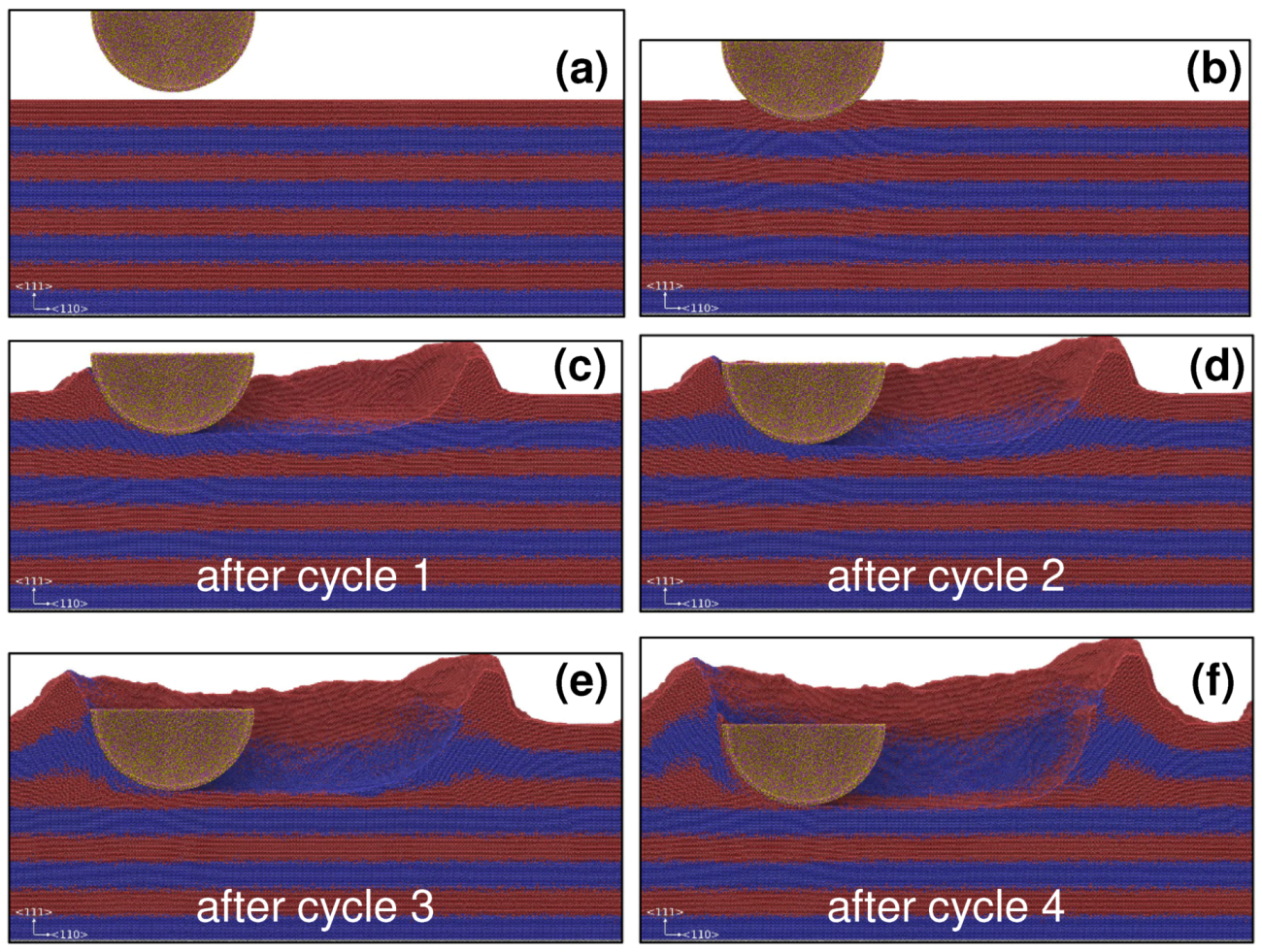
Figure 3.
Indentation depth as a function of the sliding cycle at normal forces of 300, 620 and 1000 eV Å. The horizontal shaded area represents the intermixed volume around the interfaces due to Cu-Au interdiffusion. The inset shows a snapshot of the atomic system near the sudden drop event observed for the 1000 eV Å case marked by a black arrow (see text for more information). Atoms in the inset are colored after their local atomic shear strain using the color-map displayed at the bottom. The atomic strains are computed using two consecutive snapshots separated by 50 ps (corresponding to a sliding distance of ∼2.5 nm). Interfaces are indicated by white dashed lines.

Figure 4.
Normal (a) and lateral (b) force on the indenter over the sliding cycles for three loading conditions, that is, normal forces of , and eV Å. The thick colored lines in (a) show the floating overage of the normal force over a period of 50 ps, the thin lines show the full data. (c) Sequence of snapshots taken during cycle 3 at eV Å at the positions within the friction loop indicated by arrows in (b).

Figure 5.
Reciprocating sliding simulation snapshots with a force of 1000 eV Å after (a,d) indentation, (b,e) half a stroke and (c,f) one full stoke. Atoms in panels (a–c) are colored after their local atomic shear strain values. Atoms with a atomic shear strain value lower than 0.2 are removed for clarity. The atomic strains are computed using the relaxed undeformed state of the system a the reference configuration. Panels (d–f) shows the corresponding common neighbor analysis (CNA). Atoms in red are in an HCP local environment, atoms in blue are in a BCC local environment, atoms in white are in an undefined local environment. In the CNA snapshots, all the FCC atoms have been removed for clarity.

© 2019 by the authors. Licensee MDPI, Basel, Switzerland. This article is an open access article distributed under the terms and conditions of the Creative Commons Attribution (CC BY) license (http://creativecommons.org/licenses/by/4.0/).
Share and Cite
MDPI and ACS Style
Gola, A.; Pastewka, L. Scratching Cu|Au Nanolaminates. Lubricants 2019, 7, 44. https://doi.org/10.3390/lubricants7050044
AMA Style
Gola A, Pastewka L. Scratching Cu|Au Nanolaminates. Lubricants. 2019; 7(5):44. https://doi.org/10.3390/lubricants7050044
Chicago/Turabian StyleGola, Adrien, and Lars Pastewka. 2019. "Scratching Cu|Au Nanolaminates" Lubricants 7, no. 5: 44. https://doi.org/10.3390/lubricants7050044
Note that from the first issue of 2016, this journal uses article numbers instead of page numbers. See further details here.