Quarter Century Development of Laser Peening without Coating


1
Institute for Molecular Science, National Institutes of Natural Sciences, Okazaki 444-8585, Japan
2
Institute of Scientific and Industrial Research, Osaka University, Ibaraki 567-0047, Japan
Metals 2020, 10(1), 152; https://doi.org/10.3390/met10010152
Submission received: 4 January 2020
/
Revised: 13 January 2020
/
Accepted: 17 January 2020
/
Published: 19 January 2020
(This article belongs to the Special Issue Laser Shock Processing and Related Phenomena)
Abstract
:This article summarizes the development of laser peening without coating (LPwC) during the recent quarter century. In the mid-1990s, the study of LPwC was initiated in Japan. The objective at that time was to mitigate stress corrosion cracking (SCC) of structural components in operating nuclear power reactors (NPRs) by inducing compressive residual stresses (RSs) on the surface of susceptible components. Since the components in NPRs are radioactive and cooled underwater, full-remote operation must be attained by using lasers of water-penetrable wavelength without any surface preparation. Compressive RS was obtained on the top-surface by reducing pulse energy less than 300 mJ and pulse duration less than 10 ns, and increasing pulse density (number of pulses irradiated on unit area). Since 1999, LPwC has been applied in NPRs as preventive maintenance against SCC using frequency-doubled Q-switched Nd:YAG lasers (λ = 532 nm). To extend the applicability, fiber-delivery of intense laser pulses was developed in parallel and has been used in NPRs since 2002. Early first decade of the 2000s, the effect extending fatigue life was demonstrated even if LPwC increased surface roughness of the components. Several years ago, it was confirmed that 10 to 20 mJ pulse energy is enough to enhance fatigue properties of weld joints of a structural steel. Considering such advances, the development of 20 mJ-class palmtop-sized handheld lasers was initiated in 2014 in a five-year national program, ImPACT under the cabinet office of the Japanese government. Such efforts would pave further applications of LPwC, for example maintenance of infrastructure in the field, beyond the horizons of the present laser systems.
1. Introduction
Progress in laser science and technology has realized advanced processes and applications in industries. Development of laser peening without coating (LPwC) is a landmark to deploy high-power lasers for maintenance work of infrastructure in the field. LPwC has advantage because of inertia-less process over mechanical treatment in operating nuclear facilities [1,2]. LPwC introduces compressive residual stresses (RSs) on metallic materials by simply irradiating successive laser pulses to the bare surface of components covered with water [3]. A remote processing system of LPwC was developed and has been applied to components of existing nuclear power reactors (NPRs) to mitigate stress corrosion cracking (SCC) since 1999 [1].
In the earliest system of LPwC for NPRs, laser pulses travel 50 m from laser units to the reactor components through waterproof guide pipes with reflecting mirrors at corners [1]. A technology for delivering 20 MW (100 mJ, 5 ns) laser pulses using optical fiber was also developed to increase the flexibility and extend the applicability of LPwC [4,5]. A miniaturized optical head with a diameter of 10 mm was developed with a fast-responding focusing function [6,7] that controls the focal point just on the surface within an accuracy required for fiber-delivered LPwC, namely less than ±0.5 mm. By integrating these technologies, fiber-delivery has been utilized in NPRs since 2002 [2].
Regarding fatigue issues, LPwC has positive effects to improve mechanical properties of various materials including ceramics [8,9]. LPwC significantly enhanced the fatigue strength and prolonged the fatigue life of steels [10,11,12], aluminum alloys [13] titanium alloys [14,15], etc. Recently, Sakino et al. confirmed the effect enhancing fatigue properties of HT780 (780 MPa grade high-strength steel) by low-energy LPwC with pulse energies down to 20 and 10 mJ [16]. Considering these advances, the Japanese government launched a five-year national program, ImPACT (Impulsing PAradigm Change through Disruptive Technologies) in 2014 to develop compact high-power pulsed lasers including 20 mJ-class palmtop-sized handheld lasers [17], which brings about further applications beyond the horizons of the present LPwC by realizing a portable system with the handheld lasers, for example applications to infrastructure in the field such as bridges, windmills, etc.
In this article, the development of LPwC in the recent quarter century is reviewed including the perspective brought by palmtop-sized handheld lasers.
2. Fundamental Process of LPwC
The fundamental process of LPwC is illustrated in Figure 1a [18]. When the high-power laser pulse with a duration of several nanoseconds is focused on the material, the top surface immediately transforms into plasma through ablative interaction with the laser pulse. If the surface of the material is covered with water, the pressure of the plasma significantly increases because the inertia of the water prevents expansion of the plasma. Under certain conditions, the peak pressure becomes 10 to 100 times higher than that in air, reaching several GPa which exceeds the yield strength of most metals. A shock wave is generated by this sudden pressure rise, propagates toward inside the material and attenuates to induce plastic deformation of the material. After passage of the shock wave, compressive RS generates in the surface layer due to elastic constraint from the surrounding part.
LPwC usually employs Q-switched Nd:YAG lasers. In our development, the wavelength was halved to water-penetrable visible light (λ = 532 nm) to apply to water-immersed objects. Surface RSs become compressive by increasing the number of pulses irradiated in unit area (pulses/m2) [18], in spite of intense heat input due to the direct interaction of laser pulses with the bare surface of the objects. To make the heat input negligible the interaction time was reduced, i.e., the laser pulse duration was decreased to several nanoseconds from tens of nanoseconds in the laser peening with coating [19,20,21,22]. The pulse energy was also reduced to around 200 mJ from several tens of Joules.
In the mid-1990s, we attained surface compression by LPwC for the first time in the world [18]. This achievement is a landmark for the maintenance of NPRs because LPwC doesn’t require drainage of cooling water used for radiation shielding but only irradiates laser pulses to bare components underwater without any preparation on the surface of the components.
In case of laser peening with coating, sacrificial overlay (coating) is pasted on material [19,20,21,22], which controls laser energy absorption and prevent the surface from melting. This scheme of laser peening uses high energy Nd:glass lasers with near infrared wavelength (λ = 1.05 μm) and black polymer tape or metal foil as the coating which is pasted prior to laser irradiation and removed after the treatment. The details of the process described elsewhere [22].
3. Effects of LPwC
3.1. Effects on Residual Stress
The effect of LPwC on RS was studied through experiments. As shown in Figure 2, a sample was immersed in water and driven two-dimensionally with an X-Y stage during consecutive irradiation of laser pulses. Samples were cut out from a type-304 austenitic stainless steel plate after 20% cold-working which simulated the irradiation hardening due to fast neutrons during long-term operation of NPRs (2 × 1025 neutrons/m2, neutron energy >1 MeV). The size of the samples was 40 mm × 60 mm with 10 mm thickness and an area of 20 mm × 20 mm was processed. Laser irradiation conditions were 200 mJ pulse energy, 8 ns pulse duration, 0.8 mm focal spot diameter and 36 pulses/mm2 pulse density. This corresponds to 50 TW/m2 laser peak power density on the sample. Prior to LPwC, the sample surface was ground in the rolling direction of the original plate to introduce a tensile RS on the surface. X-ray diffraction (XRD; sin2Ψ method) was used to measure the surface RS, and the in-depth profile was estimated by alternately repeating the XRD and electrolytic polishing.
Figure 3 exhibits the RS in-depth profiles with and without LPwC together with those predicted by time-dependent elasto-plastic simulation based on finite element method (FEM) [23,24,25], which reproduced experimental results quite well in terms of magnitude and profile. It is obvious that LPwC can induce compressive RSs in the surface layer of material, typically up to around 1 mm depth.
The simulation of LPwC was made in two steps. The first one is to calculate temporal evolution of plasma pressure based on Fabbro’s model [26] in which the plasma was assumed to be an ideal gas. To calibrate the plasma pressure, we measured the expansion velocity of the plasma generated on the sample surface underwater [3], then the velocity was converted to the pressure with Fabbro’s model. The second step is to calculate the RS in-depth profile by using a home-made FEM program SAFFRON developed in a framework of a non-linear displacement-based incremental scheme [27]. The calculation system was discretized with 20-node isoparametric solid elements [23,24,25]. The plasma pressure calculated in the first step of the simulation was used as the time-dependent external load working on the sample. Stress-strain relation was modeled by the data obtained from static tensile test of the sample material. The Poisson’s ratio was assumed to be 0.28. The von Mises yield criterion and a combined hardening rule were applied in the second step of the simulation.
3.2. Effects on Fatigue Properties
Fatigue test samples were prepared from a low carbon type austenitic stainless steel (type-316L) as shown in Figure 4 [28]. Two types of heat treatments were applied to the samples before LPwC, namely full heat (FH; 1373 K, 3600 s in vacuum) treatment and stress relieving (SR; 1173 K, 3600 s). Figure 5 shows the microstructure of the materials after the heat treatments. The grain sizes of the materials after FH and SR treatments were 88 μm and 24 μm, respectively. LPwC was made with 200 mJ pulse energy, 0.8 mm spot diameter and 36 pulses/mm2 pulse density. Then, rotating bending fatigue testing (R = −1) were made with a frequency of 2820 rpm. During fatigue loading, the samples were cooled by flowing distilled water. The micro-vickers hardness (Hv) and RS were measured for the samples with and without LPwC [28].
The results showed that LPwC hardened the surface of both FH and SR materials down to about 0.6 mm from the surface. The hardness of both materials was increased by about 140 Hv with LPwC and reached about 300 Hv at just below the surfaces. The RS in-depth profiles exhibited anisotropy between longitudinal (z) and circumferential (θ) directions; σz on the surface was about −400 MPa, on the other hand σθ was about −200 MPa. The maximum compressive RSs were about −600 MPa (σz) and −400 MPa (σθ) at 60–100 µm depth.
Figure 6 shows the fatigue test results. Fatigue strengths of FH and SR materials with LPwC were 300 MPa and 340 MPa at 108 cycles, respectively, i.e., LPwC enhanced the fatigue strengths by 1.7 and 1.4 times as great as those of the reference materials. Fatigue properties enhancement was also confirmed in uniaxial fatigue of steel [16,29,30], aluminum alloy [31] and titanium alloy [15].
3.3. Effects on SCC Susceptibility and Application to NPRs
Creviced bent beam (CBB) type testing was performed to evaluate the effect of LPwC on SCC susceptibility [24]. Samples of 10 mm × 50 mm and 2 mm thick were cut out from a plate of type-304 austenitic stainless steel with thermal sensitization (893 K, 8.64 × 10⁴ s) followed by 20% cold working. As shown in Figure 7, samples were bent to make 1% tensile strain on the surface by using a curved fixture. After LPwC on the sample surface, crevices were made with graphite wool, and then the samples were immersed in 561 K water with 8 ppm dissolved oxygen and 10−4 S/m electrical conductivity for 1.8 × 10⁶ s duration by using autoclaves.
After the immersion, the surface and cross-section of all samples were precisely observed with microscopes. Inter-granular type SCC appeared in all reference samples, however no cracks were found out in samples with LPwC. Typical cross-sectional micrographs are shown in Figure 8. LPwC induced compressive RSs on the surfaces of austenitic stainless steels, nickel-based alloys and their weld metals, and prevented SCC in all tested materials [32].
Figure 9 illustrates LPwC in a boiling water reactor (BWR) [1]. Laser pulses are delivered from the laser system on the top floor of the reactor building to weld lines of the reactor core shroud with waterproof guide pipes and mirrors at corners of the piping. An elaborate beam tracking/alignment system with a fast-responding anti-vibration function was developed and implemented to control laser irradiation point within accuracy of 0.1 mm at about 50 m away from the laser system.
Fiber delivery technology was also developed to extend the applicability of LPwC [4,5]. The intense laser pulses sometimes cause damage on the inlet surface of optical fiber and, if not, the incoming laser pulses tend to converge and lead to damage inside the optical fiber due to reflection at the curved boundary between core and cladding and/or the non-linear effect of refractive index. To avoid this situation, an inlet optics with a homogenizer consist of micro lens arrays was developed, which flatten the spatial distribution of laser intensity and eliminated conceivable hot spots. Thus, the technology was established for delivering frequency-doubled Nd:YAG laser pulses with 100 mJ energy and 5 ns duration with a single optical fiber, which improves the applicability to 3D structures, together with a tiny optical head as presented in Figure 10.
4. Palmtop-Sized Handheld Laser Development
The effect of low-energy LPwC on fatigue properties was investigated for HT780 welded joints around 2013. In the course of the investigation, the pulse energy was reduced from 200 mJ to 100 mJ and then 50 mJ, the fatigue lives were significantly prolonged nevertheless [33]. Further experiments showed LPwC with the pulse energy even down to 20 mJ or 10 mJ has sufficient effects to enhance fatigue properties as shown in Figure 11 [16].
Considering such progress on the low-energy LPwC, the development of 20 mJ-class palmtop-sized handheld lasers was initiated in 2014 in a five-year Japanese national program, ImPACT [17]. A near-infrared (λ = 1.06 μm), sub-nanosecond (<1 ns) and passively Q-switched Nd:YAG laser with a weight of less than 1 kg was developed in IMS (Institute for Molecular Science ) led by Prof. Taira [34,35], as shown in Figure 12.
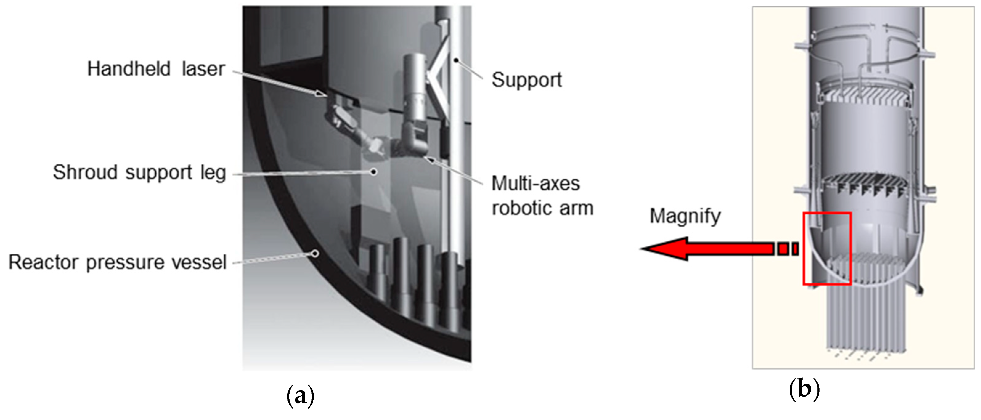
A concept of LPwC system with the handheld laser is illustrated in Figure 13. A miniaturized optical head containing the laser is manipulated by a multi-axes robotic arm. Such a simple LPwC system could certainly extend the applicability and drastically reduce the time required in all phases of applications, i.e., designing, manufacturing, system integration, testing, training, transportation, installation, operation, quality assurance and dismantling.
Compared to earlier LPwC systems with current massive lasers, the system proposed above would be much smaller and simpler taking full advantage of ultra-compact handheld lasers. The pronounced characteristics expected are as follows:
- Higher reliability and operability can be expected due to simplicity of the system, which requires fewer personnel for the operation and maintenance.
- The system is much tolerant toward ambient conditions, i.e., temperature change, vibration, etc., resulting from the smaller system volume and number of parts.
- Required laser power can be decreased due to smaller transmitting loss of laser energy resulting from the shorter optical path and simpler optics.
- Application to infrastructure such as NPRs, bridges, windmills, etc. could be easier due to the smaller and simpler system.
5. Concluding Remarks
The processes, effects, and applications of laser peening without coating (LPwC) were reviewed. A series of experimental studies clearly demonstrated that LPwC improves fatigue properties and reduces the susceptibility to stress corrosion cracking (SCC) through the impartment of compressive residual stresses (RSs) in the near surface layer of objects. LPwC has been applied to nuclear power reactors (NPRs) as a preventive maintenance against SCC of structural components since 1999 [1].
Low-energy LPwC was applied to welded joints of HT780 (780 MPa grade high-strength steel) structural steel with pulse energies down to 10 mJ. Fatigue testing revealed that the fatigue lives were sufficiently prolonged by LPwC even if 10 mJ pulse energy was used [16].
The Japanese government launched a five-year national program, ImPACT in 2014 [17], which was designed to trigger off disruptive innovation for changes in society. In the program, compact high-power pulsed lasers including 20 mJ-class palmtop-sized handheld lasers has been developed. Due to the simplicity and robustness of handheld lasers, the application including LPwC necessarily expands in various fields, for example field maintenance of infrastructure such as bridges, windmills, power plants, etc.
Funding
This work was partially supported by ImPACT Program of Council for Science, Technology and Innovation (Cabinet Office, Government of Japan).
Conflicts of Interest
The author declares no conflict of interest.
References
- Sano, Y.; Kimura, M.; Sato, K.; Obata, M.; Sudo, A.; Hamamoto, Y.; Shima, S.; Ichikawa, Y.; Yamazaki, H.; Naruse, M.; et al. Development and Application of Laser Peening System to Prevent Stress Corrosion Cracking of Reactor Core Shroud. In Proceedings of the 8th International Conference on Nuclear Engineering (ICONE-8), Baltimore, MD, USA, 2–6 April 2000. [Google Scholar]
- Yoda, M.; Chida, I.; Okada, S.; Ochiai, M.; Sano, Y.; Mukai, N.; Komotori, G.; Saeki, R.; Takagi, T.; Sugihara, M.; et al. Development and Application of Laser Peening System for PWR Power Plants. In Proceedings of the 14th International Conference on Nuclear Engineering (ICONE-14), Miami, FL, USA, 17–20 July 2006. [Google Scholar]
- Sano, Y.; Mukai, N.; Okazaki, K.; Obata, M. Residual stress improvement in metal surface by underwater laser irradiation. Nucl. Instrum. Methods Phys. Res. B 1997, 121, 432–436. [Google Scholar] [CrossRef]
- Schmidt-Uhlig, T.; Karlitschek, P.; Marowsky, G.; Sano, Y. New simplified coupling scheme for the delivery of 20 MW Nd: YAG laser pulses by large core optical fibers. Appl. Phys. B 2001, 72, 183–186. [Google Scholar] [CrossRef]
- Schmidt-Uhlig, T.; Karlitschek, P.; Yoda, M.; Sano, Y.; Marowsky, G. Laser shock processing with 20 MW laser pulses delivered by optical fibers. Eur. Phys. J. AP 2000, 9, 235–238. [Google Scholar] [CrossRef]
- Sano, Y.; Tamura, M.; Chida, I.; Suezono, N. Underwater Maintenance and Repair Technologies for Reactor Components by Laser Material Processing. In Proceedings of the 7th International Welding Symposium (7WS), Kobe, Japan, 20–22 November 2001. [Google Scholar]
- Sano, Y.; Kimura, M.; Yoda, M.; Mukai, N.; Sato, K.; Uehara, T.; Ito, T.; Shimamura, M.; Sudo, A.; Suezono, N. Development of Fiber-Delivered Laser Peening System to Prevent Stress Corrosion Cracking of Reactor Components. In Proceedings of the 9th International Conference on Nuclear Engineering (ICONE-9), Nice, France, 8–12 April 2001. [Google Scholar]
- Akita, K.; Sano, Y.; Takahashi, K.; Tanaka, H.; Ohya, S. Strengthening of Si3N4 ceramics by laser peening. Mater. Sci. Forum 2006, 524–525, 141–146. [Google Scholar] [CrossRef]
- Saigusa, K.; Takahashi, K.; Sibuya, N. Evaluation of surface properties of silicon nitride ceramics treated with laser peening. Int. J. Peen. Sci. Technol. 2019, 1, 221–232. [Google Scholar]
- Sano, Y.; Obata, M.; Kubo, T.; Mukai, N.; Yoda, M.; Masaki, K.; Ochi, Y. Retardation of crack initiation and growth in austenitic stainless steels by laser peening without protective coating. Mater. Sci. Eng. A 2006, 417, 334–340. [Google Scholar] [CrossRef]
- Sakino, Y.; Sano, Y.; Kim, Y.-C. Application of laser peening without coating on steel welded joints. Int. J. Struct. Integ. 2011, 2, 332–344. [Google Scholar] [CrossRef]
- Masaki, K.; Ochi, Y.; Matsumura, T.; Ikarashi, T.; Sano, Y. Effects of laser peening treatment on high cycle fatigue and crack propagation behaviors in austenitic stainless steel. J. Power Energy Syst. 2010, 4, 94–104. [Google Scholar] [CrossRef] [Green Version]
- Sano, Y.; Masaki, K.; Gushi, T.; Sano, T. Improvement in fatigue performance of friction stir welded A6061-T6 aluminum alloy by laser peening without coating. Mater. Des. 2012, 36, 809–814. [Google Scholar] [CrossRef]
- Maawad, E.; Sano, Y.; Wagner, L.; Brokmeier, H.-G.; Genzel, C. Investigation of laser shock peening effects on residual stress state and fatigue performance of titanium alloys. Mater. Sci. Eng. A 2012, 536, 82–91. [Google Scholar] [CrossRef]
- Altenberger, I.; Sano, Y.; Nikitin, I.; Scholtes, B. Fatigue Behavior and Residual Stress State of Laser Shock Peened Materials at Ambient and Elevated Temperatures. In Proceedings of the 9th International Fatigue Congress (FATIGUE 2006), Atlanta, GA, USA, 14–19 May 2006. [Google Scholar]
- Sakino, Y.; Sano, Y. Investigations for lowering pulse energy of laser-peening for improving fatigue strength. Q. J. Jpn. Weld. Soc. 2018, 36, 153–159. [Google Scholar] [CrossRef] [Green Version]
- Ubiquitous Power Laser for Achieving a Safe, Secure and Longevity Society under ImPACT Program. Available online: https://www.jst.go.jp/impact/sano/index.html (accessed on 31 December 2019).
- Mukai, N.; Aoki, N.; Obata, M.; Ito, A.; Sano, Y.; Konagai, C. Laser Processing for Underwater Maintenance in Nuclear Plants. In Proceedings of the 3rd JSME/ASME International Conference on Nuclear Engineering (ICONE-3), Kyoto, Japan, 23–27 April 1995. S404-3. [Google Scholar]
- Fabbro, R.; Peyre, P.; Berthe, L.; Scherpereel, X. Physics and applications of laser-shock processing. J. Laser Appl. 1998, 10, 265–279. [Google Scholar] [CrossRef]
- Peyre, P.; Chaieb, I.; Braham, C. FEM calculation of residual stresses induced by laser shock processing in stainless steels. Model. Simul. Mater. Sci. Eng. 2007, 15, 205–221. [Google Scholar] [CrossRef]
- Fairand, B.P.; Clauer, A.H.; Jung, R.G.; Wilcox, B.A. Quantitative assessment of laser-induced stress waves generated at confined surfaces. Appl. Phys. Lett. 1974, 25, 431–433. [Google Scholar] [CrossRef]
- Sokol, D.W.; Clauer, A.H.; Ravindranath, R. Applications of Laser Peening to Titanium Alloys. In Proceedings of the ASME/JSME 2004 Pressure Vessels and Piping Division Conference, San Diego, CA, USA, 25–29 July 2004. [Google Scholar]
- Sano, Y.; Kimura, M.; Mukai, N.; Yoda, M.; Obata, M.; Ogisu, T. Process and Application of Shock Compression by Nano-Second Pulses of Frequency-Doubled Nd: YAG Laser. In Proceedings of the International Forum on Advanced High-Power Lasers and Applications (AHPLA’99), Osaka, Japan, 1–5 November 1999. [Google Scholar]
- Sano, Y.; Mukai, N.; Yoda, M.; Ogawa, K.; Suezono, N. Underwater laser shock processing to introduce residual compressive stress on metals. Mater. Sci. Res. Int. 2001, 2, 453–458. [Google Scholar]
- Sano, Y.; Yoda, M.; Mukai, N.; Obata, M.; Kanno, M.; Shima, S. Residual stress improvement mechanism on metal material by underwater laser irradiation. J. Atom. Energy Soc. Jpn. 2000, 42, 567–573. [Google Scholar] [CrossRef] [Green Version]
- Fabbro, R.; Fournier, J.; Ballard, P.; Devaux, D.; Virmont, J. Physical Study of Laser-produced Plasma in Confined Geometry. J. Appl. Phys. 1990, 68, 775–784. [Google Scholar] [CrossRef]
- Sano, Y. A Finite Element Method for Contact Problems between Three-Dimensional Curved Bodies. J. Nucl. Sci. Technol. 1996, 33, 119–127. [Google Scholar] [CrossRef]
- Ochi, Y.; Masaki, K.; Matsumura, T.; Wakabayashi, Y.; Sano, Y.; Kubo, T. Effects of Laser Peening on High Cycle Fatigue Properties in Austenitic Stainless Steel. In Proceedings of the 12th International Conference on Experimental Mechanics (ICEM12), Bari, Italy, 29 August–2 September 2004. [Google Scholar]
- Sakino, Y.; Sano, Y.; Sumiya, R.; Kim, Y.-C. Major factor causing improvement in fatigue strength of butt welded steel joints after laser peening without coating. Sci. Technol. Weld. Join. 2012, 17, 402–407. [Google Scholar] [CrossRef]
- Sano, Y.; Sakino, Y.; Mukai, N.; Obata, M.; Chida, I.; Uehara, T.; Yoda, M.; Kim, Y.-C. Laser peening without coating to mitigate stress corrosion cracking and fatigue failure of welded components. Mater. Sci. Forum 2008, 519, 580–582. [Google Scholar] [CrossRef]
- Adachi, T.; Takehisa, H.; Nakajima, M.; Sano, Y. Effect of Laser Peening on Fatigue Properties for Aircraft Structure Parts. In Proceedings of the 10th International Conference on Shot Peening (ICSP10), Tokyo, Japan, 15–18 September 2008. [Google Scholar]
- Sano, Y.; Obata, M.; Yamamoto, T. Residual stress improvement of weldment by laser peening. Weld. Int. 2006, 20, 598–601. [Google Scholar] [CrossRef]
- Sakino, Y.; Yoshikawa, K.; Sano, Y.; Sumiya, R.; Kim, Y.-C. A basic study for application of laser peening to large-scale steel structure. Q. J. Jpn. Weld. Soc. 2013, 31, 231–237. [Google Scholar] [CrossRef] [Green Version]
- Zheng, L.; Kausas, A.; Taira, T. Drastic thermal effects reduction through distributed face cooling in a high power giant-pulse tiny laser. Opt. Mater. Exp. 2017, 7, 3214–3221. [Google Scholar] [CrossRef]
- Ubiquitous Power Laser for Achieving a Safe, Secure and Longevity Society under ImPACT Program. Available online: https://www.youtube.com/watch?v=nMsOkkEPK5I (accessed on 31 December 2019).
Figure 1.
Fundamental process: (a) Laser peening without coating (LPwC); (b) Laser peening with coating (sacrificial overlay).
Figure 1.
Fundamental process: (a) Laser peening without coating (LPwC); (b) Laser peening with coating (sacrificial overlay).

Figure 2.
Experiment of underwater LPwC.
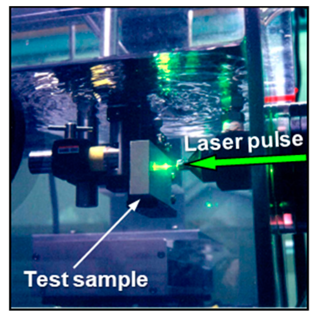
Figure 3.
Residual stress in-depth profiles of 20% cold-worked type-304 austenitic stainless steel. Time-dependent elasto-plastic simulation based on a finite element method (FEM) well reproduces the experimental result.
Figure 3.
Residual stress in-depth profiles of 20% cold-worked type-304 austenitic stainless steel. Time-dependent elasto-plastic simulation based on a finite element method (FEM) well reproduces the experimental result.

Figure 4.
Type-316L austenitic stainless steel sample: (a) Dimensions; (b) External appearance. The color of the center part changed from metallic to grayish due to direct laser irradiation.
Figure 4.
Type-316L austenitic stainless steel sample: (a) Dimensions; (b) External appearance. The color of the center part changed from metallic to grayish due to direct laser irradiation.
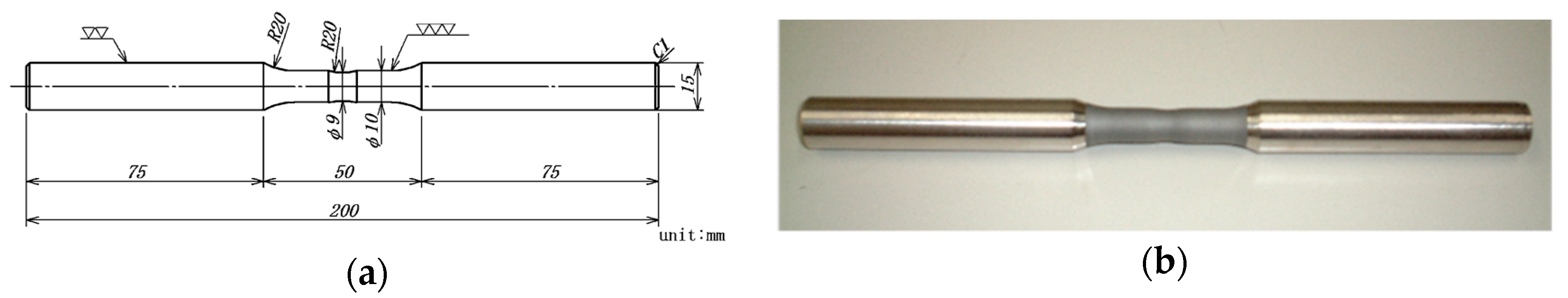
Figure 5.
Microstructure of type-316L austenitic stainless steel: (a) Full heat-treated (FH); (b) Stress-relieved (SR).
Figure 5.
Microstructure of type-316L austenitic stainless steel: (a) Full heat-treated (FH); (b) Stress-relieved (SR).

Figure 6.
Rotating bending fatigue test results of type-316L austenitic stainless steel. Fatigue strengths of FH and SR materials were increased by LPwC by 70% and 40%, respectively.
Figure 6.
Rotating bending fatigue test results of type-316L austenitic stainless steel. Fatigue strengths of FH and SR materials were increased by LPwC by 70% and 40%, respectively.
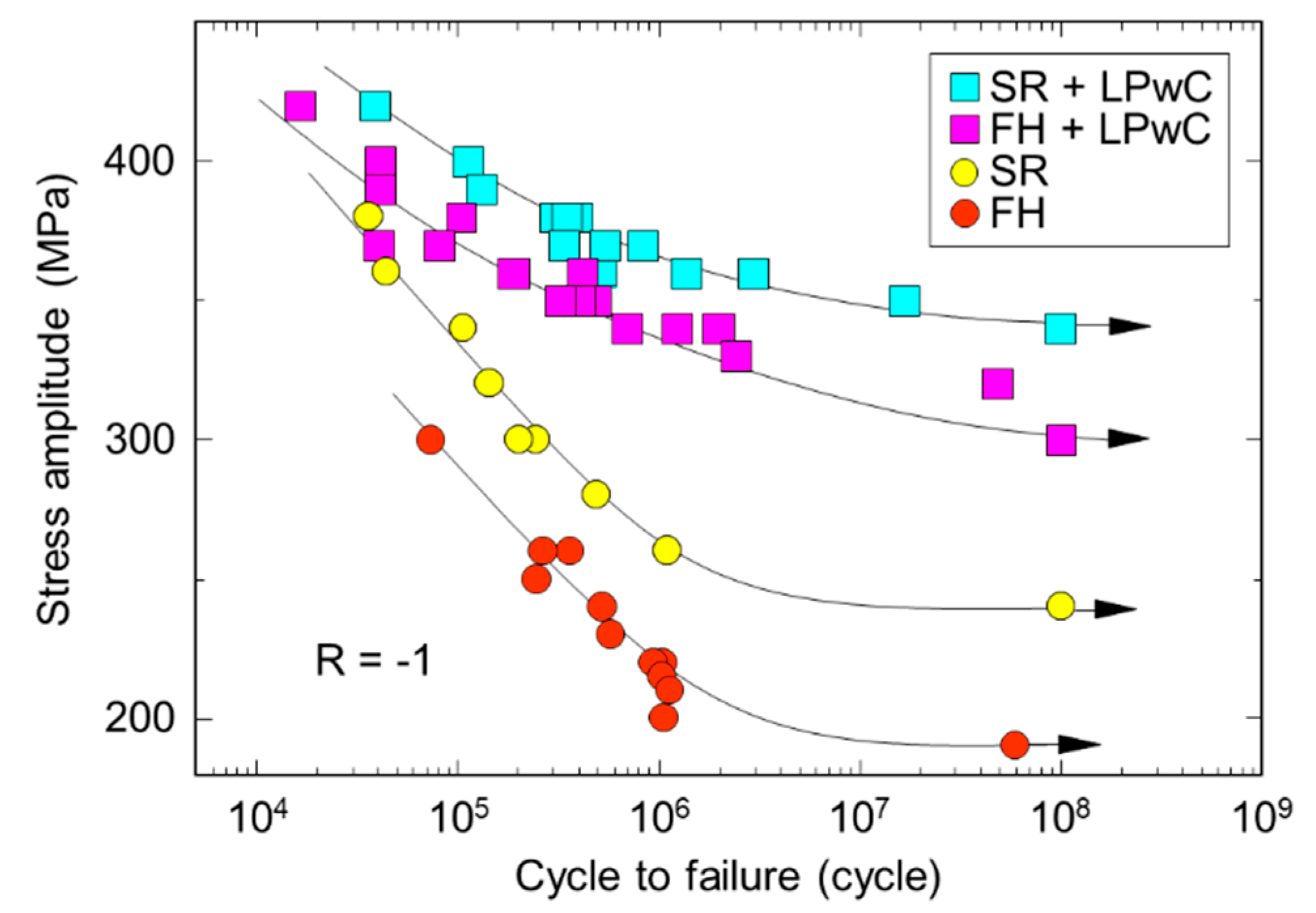
Figure 7.
Procedure of accelerating stress corrosion cracking (SCC) test: (a) Sample setting and LPwC; (b) Preparation of crevices on sample surface for immersion in autoclave.
Figure 7.
Procedure of accelerating stress corrosion cracking (SCC) test: (a) Sample setting and LPwC; (b) Preparation of crevices on sample surface for immersion in autoclave.
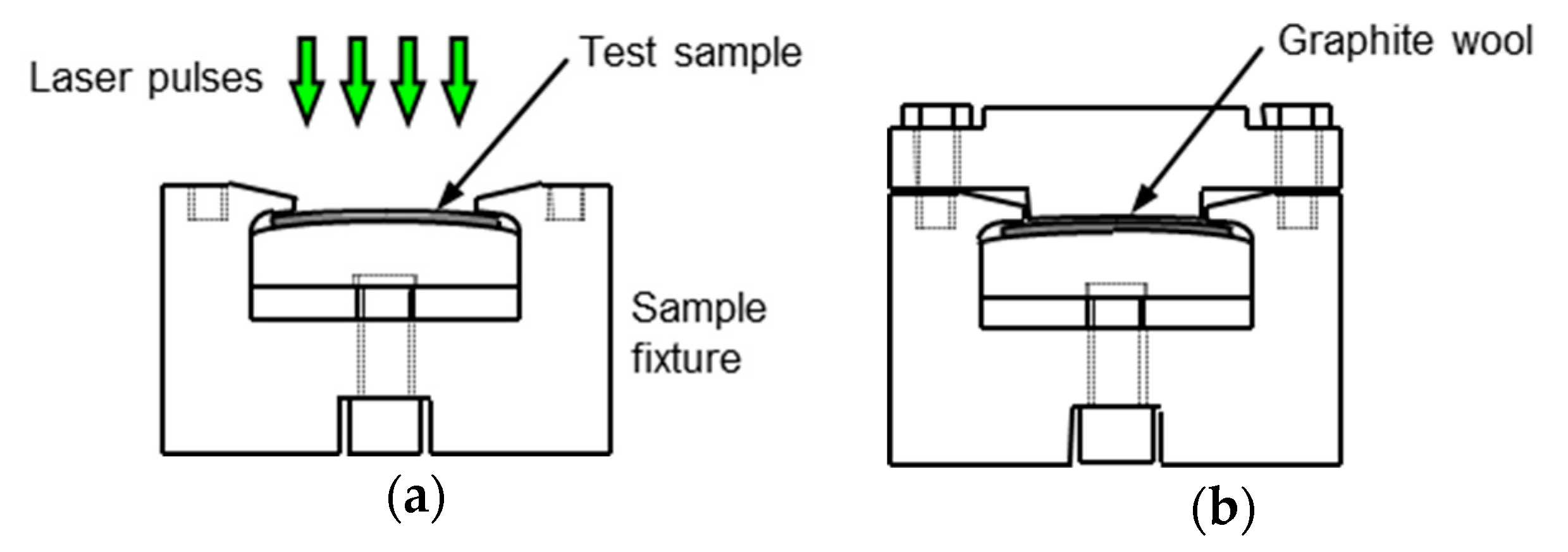
Figure 8.
SCC test results of type-304 austenitic stainless steel: (a) Cross-section of reference material (unpeened); (b) Material with LPwC.
Figure 8.
SCC test results of type-304 austenitic stainless steel: (a) Cross-section of reference material (unpeened); (b) Material with LPwC.

Figure 9.
Schematic of LPwC for weld lines of a reactor core shroud in a boiling water reactor (BWR).
Figure 9.
Schematic of LPwC for weld lines of a reactor core shroud in a boiling water reactor (BWR).

Figure 10.
Fiber-delivered LPwC: (a) Optical head; (b) Mockup experiment for the bottom of a BWR.

Figure 11.
Fatigue test results of 780 MPa grade high-strength steel (HT780) welded joints. LPwC with 10 mJ and 20 mJ pulse energies significantly extends the fatigue life.
Figure 11.
Fatigue test results of 780 MPa grade high-strength steel (HT780) welded joints. LPwC with 10 mJ and 20 mJ pulse energies significantly extends the fatigue life.
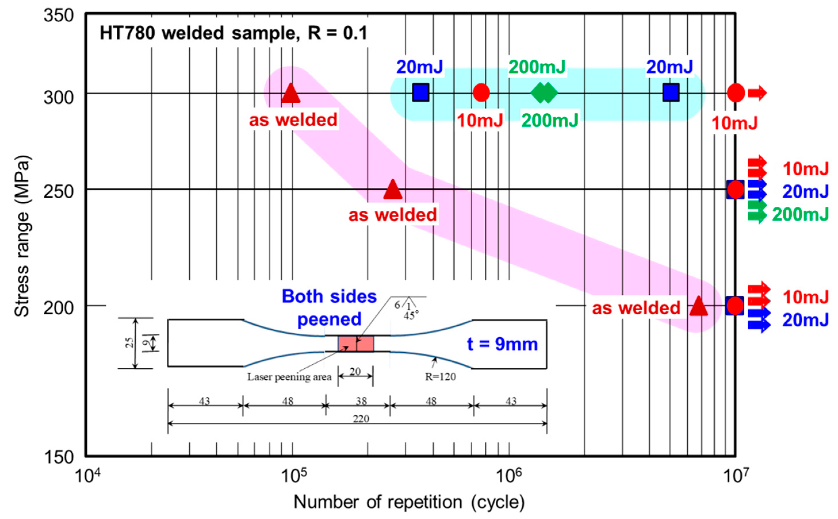
Figure 12.
Palmtop-sized handheld laser: (a) External appearance; (b) Handheld laser manipulated by a robotic arm along a pipe object. Neither the movement nor vibration affects the function of the handheld laser.
Figure 12.
Palmtop-sized handheld laser: (a) External appearance; (b) Handheld laser manipulated by a robotic arm along a pipe object. Neither the movement nor vibration affects the function of the handheld laser.
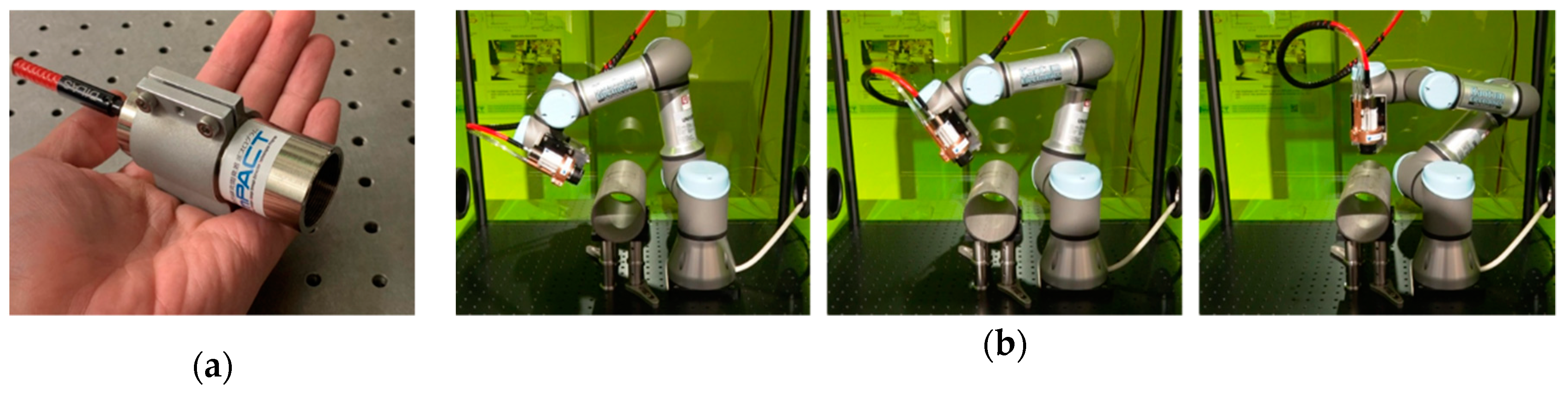
Figure 13.
Schematic of LPwC using a handheld laser for SCC mitigation in a BWR: (a) Concept to apply LPwC to hidden weld lines; (b) Cutaway view of a reactor pressure vessel in outage. The concept reduces the scale of LPwC system and laser transmission distance from tens of meters (~50 m) to tens of millimeters (~0.05 m).
© 2020 by the author. Licensee MDPI, Basel, Switzerland. This article is an open access article distributed under the terms and conditions of the Creative Commons Attribution (CC BY) license (http://creativecommons.org/licenses/by/4.0/).
Share and Cite
MDPI and ACS Style
Sano, Y. Quarter Century Development of Laser Peening without Coating. Metals 2020, 10, 152. https://doi.org/10.3390/met10010152
AMA Style
Sano Y. Quarter Century Development of Laser Peening without Coating. Metals. 2020; 10(1):152. https://doi.org/10.3390/met10010152
Chicago/Turabian StyleSano, Yuji. 2020. "Quarter Century Development of Laser Peening without Coating" Metals 10, no. 1: 152. https://doi.org/10.3390/met10010152
Note that from the first issue of 2016, this journal uses article numbers instead of page numbers. See further details here.