Characterization of Ni–CNTs Nanocomposites Produced by Ball-Milling
by
 , , and
Íris Carneiro
1, 
Filomena Viana
1,2,
Manuel F. Vieira
1,2,
José Valdemar Fernandes
3 and
Sónia Simões
1,2,* 1
CEMMPRE, Department of Metallurgical and Materials Engineering, University of Porto, R. Dr Roberto Frias, 4200-465 Porto, Portugal
2
INEGI-Institute of Science and Innovation in Mechanical and Industrial Engineering, R. Dr Roberto Frias, 4200-465 Porto, Portugal
3
CEMMPRE, Department of Mechanical Engineering, University of Coimbra, Rua Luís Reis Santos, Pinhal de Marrocos, 3030-788 Coimbra, Portugal
*
Author to whom correspondence should be addressed.
Metals 2020, 10(1), 2; https://doi.org/10.3390/met10010002
Submission received: 23 November 2019
/
Revised: 12 December 2019
/
Accepted: 16 December 2019
/
Published: 18 December 2019
(This article belongs to the Special Issue Metal Matrix Composites Reinforced with Carbon Nanotubes)
Abstract
:This research focuses on the characterization of a metal matrix nanocomposite (MMNC) comprised of a nickel matrix reinforced by carbon nanotubes (CNTs). The aim of this study was to characterize Ni–CNTs nanocomposites produced by powder metallurgy using ball-milling. CNTs were initially untangled using ultrasonication followed by mixture/dispersion with Ni powder by ball-milling for 60, 180, or 300 min. The mixtures were cold-pressed and then pressureless sintered at 950 °C for 120 min under vacuum. Their microstructural characterization was mainly performed by optical microscopy (OM), scanning electron microscopy (SEM), and electron backscatter diffraction (EBSD). The mechanical properties were evaluated by Vickers microhardness. The results indicate that combining ultrasonication and ball-milling can successfully produce Ni–CNTs nanocomposites. The ball-milling time has a significant effect on both the CNT dispersion and the final nanocomposite microstructure.
1. Introduction
The development of metal matrix nanocomposites (MMNCs) is still an exciting topic in the scientific community due to the potential of obtaining unique advanced materials. For instance, advanced lightweight composites are excellent candidates to fulfil some needs of the aerospace industry. In this sense, one of the most-explored issues by researchers has been to understand the potential use of nanometric reinforcements for the production of unique nanocomposites. Among other reinforcements, carbon nanotubes (CNTs) have already proved to be an excellent reinforcement material for various metal matrices, such as Ni [1,2,3,4,5,6,7], Cu [8,9,10,11,12,13], Ti [14,15,16,17,18,19], Mg [20,21,22,23,24], Al [25,26,27,28,29,30,31,32,33,34], and their alloys [20,35,36,37,38]. However, to meet application requirements, it is essential to combine the suitable production of nanocomposites with improved mechanical properties, which can only be achieved with uniform dispersion of the reinforcing material [39,40]. The efficiency of the strengthening mechanisms is often correlated with the nanocomposite production technique, particularly reinforcement dispersion methods. For this reason, it is crucial to ensure the use of an effective production route for the development of nanocomposites that promotes the uniform dispersion of CNTs, which should be undamaged and well-bonded to the metallic matrices in order for the strengthening mechanisms to be effective in nanocomposites [39,41].
Although there are diverse production techniques, powder metallurgy (PM) is considered one of the most efficient, and is often used to produce these nanocomposites [42,43,44,45,46]. This method is based upon four fundamental steps: manufacturing the powder(s), mixture and dispersion of the reinforcement particles and the matrix metallic powders, pressing of the powders to form compacts, and sintering. However, the production of these MMNCs still faces some challenges, such as unfavorable chemical reaction between CNTs and metal, poor interfacial bonding between reinforcement and matrix, and difficulties in achieving a uniform dispersion of CNTs throughout the matrix. This last aspect is crucial since only a homogeneous dispersion of CNTs results in a high-performance nanocomposite [39,47].
One of the most widely used dispersion methods for metal matrix nanocomposites is ball-milling, performed in a container with high-hardness balls. During ball-milling, the metallic powders are continuously fractured and re-welded, entrapping the CNTs inside. Since milling motion is responsible for untangling the CNT agglomerates, the duration of the process is a useful and valuable parameter to analyze. Milling time also influences the shape of the particles, and as milling time increases, the powders generally become flattened, which can later affect the density after pressing [18,26].
Esawi et al. [48,49], Morsi and Esawi [50], and Liu et al. [34] investigated the effect of CNTs content and ball-milling time on the mechanical properties of Al–CNTs nanocomposites produced using the ball-milling technique. These studies showed that the technique was efficient for nanocomposite production, as a strengthening effect occurred due to the strong bond between the reinforcement and the matrix. However, excessive cold-welding often occurs when long milling times are used, which can be undesirable; in this case, control agents such as methanol can be successfully used. On the other hand, Bundy et al. [51] addressed the effect of CNTs length on Ni–CNTs mixtures obtained by ball-milling. To improve the dispersion of CNTs, the authors combined two different dispersion techniques—ultrasonic bath, and ball-milling. The results demonstrate that the initial CNT length affects the CNT distribution during the ball-milling, as well as the Ni–CNTs particle morphology.
Although ball-milling is one of the most attractive processes for the industrial production of these nanocomposites, many works have shown that the damage of the reinforcement is significant, affecting the final potential properties of these materials. Thus, some studies report new approaches to the dispersion process in order to act and reduce the damage of CNTs. These new approaches involve using combined dispersion techniques, or wet environments and/or dispersion agents in the ball-milling, to help break up CNT agglomerates and thus achieve good dispersion without increasing ball-milling time [27,34,48]. Some studies are reporting promising results with the use of these new approaches applied to the ball-milling process for Al–CNT nanocomposites, but there is still little work done with other matrices (i.e., Ni).
Given this limited research, the main objective of the present work was to produce MMNCs with a nickel matrix reinforced by CNTs and to evaluate the use of the ball-milling process in order to obtain a uniform CNT dispersion in the matrix. Microstructural and mechanical characterizations were performed to evaluate the influence of ball-milling time on reinforcement dispersion and in the final microstructure and properties of the nanocomposite.
2. Materials and Methods
The nickel powders (Goodfellow Cambridge Ltd., Huntingdon, UK) and the multi-walled carbon nanotubes (MWCNTs; Fibermax Nanocomposites Ltd., London, UK) used in this study have been characterized in previous works [1,27,42].
The nanocomposites were produced with 1.00% vol. This percentage was selected based on previous results [25,42] which show that this concentration presented the best dispersion of CNTs in different matrices, using the ultrasonication method.
MWCNTs ultrasonication was performed for 5 min at 20,400 kHz to untangle some larger aggregates, before the dispersion/mixture process of CNTs and Ni powders by ball-milling.
The dispersion/mixture of the previously untangled MWCNTs in the Ni powder was performed by ball-milling. In order to reduce CNT damage, and according to the results obtained in a previous study [27] with the same CNTs but using Al as matrix, the ball-milling process was performed using isopropanol in a stainless-steel container and balls of ≈9.98 ± 0.02 mm diameter, with a ball-to-powder ratio (BPR) of 20:1.
The ball-milling method was performed at a speed of 150 rpm, for 60, 180, or 300 min. A schematic illustration of the full process of disentanglement of MWCNTs followed by their dispersion/mixture in the Ni powders can be seen in Figure 1. After filtration and drying, the powder mixtures were pressed at 900 MPa, producing compacts of 10 mm diameter and ≈3 mm thickness, which were then sintered at 950 °C for 120 min under a vacuum of 10−2 Pa.
Microstructural characterization of Ni–CNTs nanocomposites was performed by optical microscopy (OM) using a Leica DM 4000 M with a Leica DFC 420 camera (Leica Microsystems, Wetzlar, Germany) and the software Leica LAS (version 4.13.0, Leica Microsystems, Wetzlar, Germany), and by scanning electron microscopy (SEM) with an electron backscatter diffraction (EBSD) detector, employing a FEI QUANTA 400 FEG SEM (FEI Company, Hillsboro, Or, USA) with an EDAX-TSL OIM EBSD system (EDAX Inc. (Ametek), Mahwah, NJ, USA).
The roundness values of the powders were obtained by image analysis with the Leica LAS software, while for the powder size distributions, 200 particles were measured using Image J software (version 1.51, Wayne Rasban, National Institutes of Health, Bethesda MD, USA). The average grain size of the sintered samples was the result of ≈500 grain measurements in each sample using the Image J software. These measurements were performed on optical images of the samples previously etched with a solution of 10 mL H2SO4, 100 mL HCl, and 10 g CuSO4, at room temperature for times between 0.5 and 2 min, to reveal the grain boundaries [52]. The nanocomposites’ fracture surfaces were obtained by striking notched samples with a small load.
The raw EBSD data were submitted to a dilation clean-up routine, with a grain tolerance angle of 15° and minimum grain size of 2 points to avoid untrue results from incorrect pattern indexation. This cleanup procedure checks for an incorrect indexing indication in each point of the map, including isolated or low-confidence factor points. The plotted EBSD maps, inverse pole figures (IPFs), kernel average misorientation (KAM), and grain orientation spread (GOS) were obtained, and the data were treated similarly to the maps used in a previous study [53].
For mechanical evaluation, Vickers microhardness tests were performed on Ni and Ni–CNTs samples produced under the same processing conditions. The tests were performed using a Duramin-1 (Duramin-1; Struers A/S, Ballerup, Denmark) equipment. Indentation matrices with ten columns and ten rows with an indentation distance of 100 µm were performed using a low indentation load of 490 mN.
3. Results and Discussion
3.1. Influence of Ball-Milling Time on Powders Morphology
The characterization of the ball-milled powders is fundamental since particle morphology affects the porosity and microstructure of the nanocomposites. Therefore, the influence of the ball-milling time on the size and roundness of the powders was analyzed by OM. It was observed that the presence of CNTs did not influence the Ni powders’ morphology—that is, no difference was observed between samples with and without CNTs.
Figure 2 shows OM images, sizes, and roundness distributions of the Ni–CNTs powder particles obtained for different times of dispersion/mixture by ball-milling. By the observation of the OM images, the significant effect of the ball-milling time on the particle morphology is visible. As the ball-milling time increased, the particles became more elongated, which is especially evident in the sample ball-milled for 300 min. This observation was confirmed by the roundness distribution in the graphs on the left side of Figure 2. In these graphs, a particle is defined as perfectly round with a roundness value of 1. The percentage of round particles decreased from 67% to 37% with the increase of ball-milling time from 60 to 300 min.
The value of D50 was similar for all three samples. Small changes in the powder size distribution were measured; as the ball-milling time increased from 60 to 180 min, a slight decrease in D50 was observed, which increased again for the ball-milling time of 300 min. Similar trends are reported by Bundy et al. [51] who investigated Ni–CNTs mixtures using ball-milling with methanol, a BPR of 5:1, and a speed of 1750 rpm. For milling times between 90 and 360 min, the results revealed a D50 in the range ≈ 20–25 µm when using longer MWCNTs (10 to 30 µm in length) and a D50 ≈ 13–23 µm when using shorter MWCNTs (0.2 to 5.0 µm in length). For mixtures with the shorter CNTs, a decrease in D50 was observed when ball-milling time increased from 90 to 270 min and there was an increase in the D50 value for higher ball-milling times. The authors attribute this to an initial particle fracture that reduced its size up to a ball-milling time of 270 min, while for more prolonged periods re-welding occurred due to the increased surface area of the particles, which promoted the increase of the particle size.
For more detailed observation of the powder morphology, SEM analysis was performed. Figure 3 presents the images of as-received Ni powders and Ni–CNTs powders after ball-milling for 60 min. As already noted concerning OM analysis, a significant difference was observed between the morphology of these two powders after 60 min of ball-milling. Due to the ball-milling process, the particles became longer and less round. In the detail of Figure 3b, the presence of CNTs within the Ni particles is visible.
In addition to changing the morphology of Ni powders, increasing the ball-milling time also affected the structure of CNTs, with shorter CNTs dispersed in Ni particles. Some studies [50,54] report deformation, cold welding, and fragmentation of particles during the ball-milling process, as well as morphological changes and damage of the CNTs structure. Tucho et al. [54] investigated the effect of the ball-milling process on CNTs damage and observed that this process led to the CNTs’ transformation into short, open-topped nanotubes because of the high pressure generated locally from the collisions between balls in the milling chamber. In the mentioned work, it was possible to reduce CNTs’ damage using wet milling. The present work used isopropanol to reduce the number and size of CNT clusters while preventing structural damage.
3.2. Influence of Ball-Milling Time on the Nanocomposites’ Microstructure
Once the study of the effect of ball-milling duration on the powder particles was completed, it was then crucial to study this effect on sintered specimens. The characterization was initially performed using OM images, as exemplified in Figure 4a–c, for the global study of the samples microstructure, evaluating porosity and CNT agglomerates.
The percentages of porosity and agglomerates were measured in the cross-section OM images (which are not distinguishable by OM), as shown in Table 1. This analysis revealed a higher value for the Ni–CNTs than for Ni, regardless of the ball-milling conditions. For both materials, porosity decreased with the ball-milling duration, which could be due to changing particle morphology.
The presence and morphology of the CNTs agglomerates were evident in the fracture surfaces of the nanocomposites. In the image of the fracture surface of the sample produced with 180 min of ball-milling (Figure 4e), CNTs were also observed in the Ni matrix. Although the sample with 300 min of ball-milling showed lower porosity measurements, it presented some plate structures and larger agglomerates, which could reduce the strengthening effect.
To further evaluate the effect of the presence of CNTs on the nanocomposites’ microstructures, EBSD analysis was used. With this analysis, inverse pole figure (IPF) maps and the second-neighbor kernel average misorientation (KAM) maps were generated, as observed in Figure 5.
Combining IPF and KAM maps allows the influence of the process on the nanocomposite microstructure to be evaluated, namely, in terms of grain size and deformation structures [55,56].
The IPF maps indicate that nanocomposites had grains with twins. As the ball-milling time increased, it can be seen that the grains’ geometry changed from equiaxed to elongated. Another important feature we observed is that for longer ball-milling times, both IPF and KAM maps show zones within the grains with different orientations.
The average grain size of the sintered samples is presented in Table 2. The grain size can be affected by the presence of CNTs, and the evaluation of this microstructure feature is crucial since it has a substantial influence on mechanical properties. The average grain size seemed to decrease with increasing ball-milling time, which can be explained by the deformation that occurs during the dispersion/mixing process. While the CNTs can be an obstacle to the movement of grain boundaries, thus inhibiting grain growth during sintering which results in small grain size, the deformation can also influence the grain size due to the decrease of the Ni particles during the ball-milling process or even with the formation of dislocation cell structures. It is essential to evaluate these microstructure features, as they significantly affect the mechanical properties of nanocomposites.
The KAM maps presented in Figure 5 show that increasing the ball-milling time promoted misorientation within the grains due to the deformation of the particles. Evidence of this effect remained even after sintering. In the powder sample ball-milled for 60 min, the KAM maps show only a few red dots (≅5° misorientation) around the pores and CNT clusters. The powder sample ball-milled for 180 min shows more intense red areas indicative of pronounced deformation, although some blue (less than 1° misorientation), that is, less-deformed areas, are also visible. With a 300 min dispersion, the maps reveal general deformation, with almost no blue areas. These results indicate that the remaining deformation in the nanocomposite microstructures after sintering increased proportionally to the ball-milling time. This remaining deformation could be associated with subgrain boundary structures with an average size that decreases with increasing ball-milling time.
The SEM images and EBSD maps indicate that, among the three tested conditions, 180 min was the more efficient production time, presenting a more homogenous dispersion of the reinforcement, with few local deformations in the microstructure.
3.3. Characterization of Ni–CNTs Nanocomposite Produced with 180 min of Ball-Milling
As the ball-milling dispersion for 180 min revealed a more effective dispersion condition of the CNTs without damage, the samples produced in this way were studied in more detail. Figure 6 shows IPF maps, with details of high-angle, low-angle, and twin boundaries, as well as grain orientation spread (GOS) maps. In these IPF maps, high-angle boundaries were defined by a misorientation greater than 15°, being representative of the grain boundaries. Dislocation cells and subgrains, represented as low-angle boundaries, are defined by misorientations in the range 5–15°. The twins represented in Figure 6 are Σ3 and Σ9, being the most common nickel twins [57,58].
Figure 6 reveals evident differences between the nickel and the nanocomposite. In the IPF detail, with grain boundaries delineated Figure 6a–c. A higher dislocation density, represented by low-angle boundaries, is visible in the nanocomposite after sintering. This detail is associated with more pronounced deformation in the nanocomposite rather than in the unreinforced nickel.
This result was also confirmed using GOS maps, which show the recrystallization state of each grain of the sample by comparing the orientation of each measured point with the average grain orientation. In this sense, by definition, the blue grains are considered as fully recrystallized, since the orientation spread value is less than 1°, and similarly the red grains are still far from recrystallization [57]. In these maps (Figure 6b–d) it is possible to note a higher amount of recrystallized grains (in blue) on the nickel sample, while the GOS map of the nanocomposite is mainly constituted by highly deformed grains (in red and yellow).
In the recrystallization process, the formation of twins is common, which is more visible in the nickel samples, confirming a more extensive recrystallization process in these samples. This difference is the result of the obstacle effect of the CNTs to dislocation slip and grain boundary movement, hindering the recovery and recrystallization processes that can occur during the sintering step, as already seen in a previous work using ultrasonication dispersion methods [53].
A detailed analysis using Vickers microhardness was performed to investigate the influence of CNTs on hardness and how this mechanical property may vary within the same sample. The hardness results confirm the choice of 180 min mixing time as the most appropriate. The increase in hardness of Ni–CNTs compared to Ni produced under the same conditions was −1%, 11%, and 8% for the times of 60, 180, and 300 min, respectively.
The hardness distribution was analyzed by performing an average of 100 indentations with the load of 490 mN and with approximately the same spacing, as shown in the optical microscopy images of Figure 7.
From the hardness distribution maps shown in Figure 7, some differences between the Ni and Ni–CNTs samples are evident; similar hardnesses were determined all over the pure nickel sample, while the hardness measurements of nanocomposites showed a higher dispersion. The Ni sample showed an average hardness of 88 HV 0.05 with a standard error of the mean of ±1, while the Ni–CNTs sample presented 104 HV 0.05, with a standard error of the mean of ±3, with a confidence index of 95%.
The nanocomposite produced with 180 min of ball-milling presented higher localized microhardness values, marked on the map by the colors yellow, orange, and red, with a maximum of 153 HV 0.05, while the Ni presented a maximum value of 100 HV 0.05. The fluctuation in hardness values in the nanocomposite is attributed to the increase in hardness in regions adjacent to the CNT agglomerates, as well as the remaining plastic deformation after sintering, as previously shown by the EBSD analysis.
4. Conclusions
The study concerning the influence of ball-milling duration on the powder particles revealed that the process affected nickel and nanocomposite powders, modifying the particle morphology, which became flatter and longer as ball-milling duration increased.
The present research also demonstrated that the combination of ultrasonication and ball-milling as dispersion/mixture techniques could be effective in the production of nickel nanocomposites reinforced by CNTs by the classical powder metallurgy route.
Microstructural characterization of the samples obtained with different ball-milling durations revealed that 180 min was associated with a higher homogeneity of the CNTs dispersion. This characterization also showed CNTs agglomerates inside pores and in the nickel matrix.
The EBSD analysis of the sintered nickel and nanocomposite produced using 180 min of ball-milling under identical conditions showed evident microstructural differences. The Ni–CNTs displayed higher plastic deformation than the nickel sample, revealing that the presence of CNTs acted as an obstacle to the dislocation rearrangement and grain boundaries movement, hindering the recovery and recrystallization processes.
CNTs influenced the hardness of nanocomposite, which was harder than pure nickel (approximately 18% higher hardness), as well as the dispersion of results. The hardness matrices showed more hardness variation for the nanocomposites due to the higher microhardness in the zones adjacent to the CNTs agglomerates.
Author Contributions
Conceptualization, Í.C.; investigation, Í.C. and S.S.; writing—original draft preparation, Í.C. and S.S; supervision, S.S. and J.V.F.; formal analysis, F.V. and M.F.V; validation, J.V.F.; writing—review and editing, F.V, M.F.V., and J.V.F. All authors have read and agreed to the published version of the manuscript.
Funding
This work was supported by funds from the Portuguese Foundation for Science and Technology (FCT) and by FEDER funds via project reference UID/EMS/00285/2019-Centre for Mechanical Engineering, Materials and Processes. One of the authors, Íris Carneiro, was supported by a PhD grant for scientific research from the Portuguese Foundation for Science and Technology (FCT), reference PD/BD/143030/2018.
Acknowledgments
The authors are grateful to CEMUP—Centro de Materiais da Universidade do Porto for expert assistance with SEM.
Conflicts of Interest
The authors declare no conflicts of interest.
References
- Simões, S.; Carneiro, Í.; Viana, F.; Reis, M.A.L.; Vieira, M.F. Microstructural Characterization of Carbon Nanotubes (CNTs)-Reinforced Nickel Matrix Nanocomposites. Microsc. Microanal. 2019, 25, 180–186. [Google Scholar] [CrossRef] [PubMed]
- Suárez, S.; Ramos-Moore, E.; Lechthaler, B.; Mücklich, F. Grain growth analysis of multiwalled carbon nanotube-reinforced bulk Ni composites. Carbon 2014, 70, 173–178. [Google Scholar] [CrossRef]
- Katzensteiner, A.; Müller, T.; Kormout, K.; Aristizabal, K.; Suarez, S.; Pippan, R.; Bachmaier, A. Influence of Processing Parameters on the Mechanical Properties of HPT-Deformed Nickel/Carbon Nanotube Composites. Adv. Eng. Mater. 2019, 21, 1800422. [Google Scholar] [CrossRef] [Green Version]
- Singh, A.R.P.; Hwang, J.Y.; Scharf, T.W.; Tiley, J.; Banerjee, R. Bulk nickel–carbon nanotube nanocomposites by laser deposition. Mater. Sci. Technol. 2010, 26, 1393–1400. [Google Scholar] [CrossRef]
- Wen, T.; Fan, K.; Zhang, F. High strength and high ductility in nickel matrix nanocomposites reinforced by carbon nanotubes and onion-like-carbon hybrid reinforcements. J. Alloys Compd. 2020, 814, 152303. [Google Scholar] [CrossRef]
- Suárez, S.; Lasserre, F.; Mücklich, F. Mechanical properties of MWNT/Ni bulk composites: Influence of the microstructural refinement on the hardness. Mater. Sci. Eng. A 2013, 587, 381–386. [Google Scholar] [CrossRef]
- An, Z.; He, L.; Toda, M.; Yamamoto, G.; Hashida, T.; Ono, T. Microstructuring of carbon nanotubes-nickel nanocomposite. Nanotechnology 2015, 26, 195601. [Google Scholar] [CrossRef]
- Faria, B.; Guarda, C.; Silvestre, N.; Lopes, J.N.C.; Galhofo, D. Strength and failure mechanisms of cnt-reinforced copper nanocomposite. Compos. Part B Eng. 2018, 145, 108–120. [Google Scholar] [CrossRef]
- Nayan, N.; Shukla, A.K.; Chandran, P.; Bakshi, S.R.; Murty, S.V.S.N.; Pant, B.; Venkitakrishnan, P.V. Processing and characterization of spark plasma sintered copper/carbon nanotube composites. Mater. Sci. Eng. A 2017, 682, 229–237. [Google Scholar] [CrossRef]
- Guiderdoni, C.; Pavlenko, E.; Turq, V.; Weibel, A.; Puech, P.; Estournès, C.; Peigney, A.; Bacsa, W.; Laurent, C. The preparation of carbon nanotube (CNT)/copper composites and the effect of the number of CNT walls on their hardness, friction and wear properties. Carbon 2013, 58, 185–197. [Google Scholar] [CrossRef] [Green Version]
- Sule, R.; Olubambi, P.A.; Sigalas, I.; Asante, J.K.O.; Garrett, J.C. Effect of SPS consolidation parameters on submicron Cu and Cu–CNT composites for thermal management. Powder Technol. 2014, 258, 198–205. [Google Scholar] [CrossRef]
- Li, H.; Misra, A.; Zhu, Y.; Horita, Z.; Koch, C.C.; Holesinger, T.G. Processing and characterization of nanostructured Cu-carbon nanotube composites. Mater. Sci. Eng. A 2009, 523, 60–64. [Google Scholar] [CrossRef]
- Pham, V.T.; Bui, H.T.; Tran, B.T.; Nguyen, V.T.; Le, D.Q.; Than, X.T.; Nguyen, V.C.; Doan, D.P.; Phan, N.M. The effect of sintering temperature on the mechanical properties of a Cu/CNT nanocomposite prepared via a powder metallurgy method. Adv. Nat. Sci. Nanosci. Nanotechnol. 2011, 2, 015006. [Google Scholar] [CrossRef]
- Li, F.X.; Hao, P.D.; Yi, J.H.; Chen, Z.; Prashanth, K.G.; Maity, T.; Eckert, J. Microstructure and strength of nano-/ultrafine-grained carbon nanotube-reinforced titanium composites processed by high-pressure torsion. Mater. Sci. Eng. A 2018, 722, 122–128. [Google Scholar] [CrossRef]
- Munir, K.S.; Zheng, Y.; Zhang, D.; Lin, J.; Li, Y.; Wen, C. Improving the strengthening efficiency of carbon nanotubes in titanium metal matrix composites. Mater. Sci. Eng. A 2017, 696, 10–25. [Google Scholar] [CrossRef]
- Xue, F.; Jiehe, S.; Yan, F.; Wei, C. Preparation and elevated temperature compressive properties of multi-walled carbon nanotube reinforced Ti composites. Mater. Sci. Eng. A 2010, 527, 1586–1589. [Google Scholar] [CrossRef]
- Kondoh, K.; Threrujirapapong, T.; Umeda, J.; Fugetsu, B. High-temperature properties of extruded titanium composites fabricated from carbon nanotubes coated titanium powder by spark plasma sintering and hot extrusion. Compos. Sci. Technol. 2012, 72, 1291–1297. [Google Scholar] [CrossRef] [Green Version]
- Li, S.; Sun, B.; Imai, H.; Mimoto, T.; Kondoh, K. Powder metallurgy titanium metal matrix composites reinforced with carbon nanotubes and graphite. Compos. Part A Appl. Sci. Manuf. 2013, 48, 57–66. [Google Scholar] [CrossRef]
- Wang, F.-C.; Zhang, Z.-H.; Sun, Y.-J.; Liu, Y.; Hu, Z.-Y.; Wang, H.; Korznikov, A.V.; Korznikova, E.; Liu, Z.-F.; Osamu, S. Rapid and low temperature spark plasma sintering synthesis of novel carbon nanotube reinforced titanium matrix composites. Carbon 2015, 95, 396–407. [Google Scholar] [CrossRef]
- Saikrishna, N.; Reddy, G.P.K.; Munirathinam, B.; Dumpala, R.; Jagannatham, M.; Sunil, B.R. An investigation on the hardness and corrosion behavior of MWCNT/Mg composites and grain refined Mg. J. Magnes. Alloy 2018, 6, 83–89. [Google Scholar] [CrossRef]
- Shi, H.L.; Wang, X.J.; Zhang, C.L.; Li, C.D.; Ding, C.; Wu, K.; Hu, X.S. A Novel Melt Processing for Mg Matrix Composites Reinforced by Multiwalled Carbon Nanotubes. J. Mater. Sci. Technol. 2016, 32, 1303–1308. [Google Scholar] [CrossRef]
- Goh, C.S.; Wei, J.; Lee, L.C.; Gupta, M. Ductility improvement and fatigue studies in Mg-CNT nanocomposites. Compos. Sci. Technol. 2008, 68, 1432–1439. [Google Scholar] [CrossRef]
- Aung, N.N.; Zhou, W.; Goh, C.S.; Nai, S.M.L.; Wei, J. Effect of carbon nanotubes on corrosion of Mg–CNT composites. Corros. Sci. 2010, 52, 1551–1553. [Google Scholar] [CrossRef]
- Han, G.Q.; Shen, J.H.; Ye, X.X.; Chen, B.; Imai, H.; Kondoh, K.; Du, W.B. The influence of CNTs on the microstructure and ductility of CNT/Mg composites. Mater. Lett. 2016, 181, 300–304. [Google Scholar] [CrossRef]
- Simões, S.; Viana, F.; Reis, M.A.L.; Vieira, M.F. Aluminum and Nickel Matrix Composites Reinforced by CNTs: Dispersion/Mixture by Ultrasonication. Metals 2017, 7, 279. [Google Scholar] [CrossRef]
- Chen, B.; Kondoh, K. Sintering Behaviors of Carbon Nanotubes—Aluminum Composite Powders. Metals 2016, 6, 213. [Google Scholar] [CrossRef] [Green Version]
- Simões, S.; Viana, F.; Reis, M.A.L.; Vieira, M.F. Microstructural Characterization of Aluminum-Carbon Nanotube Nanocomposites Produced Using Different Dispersion Methods. Microsc. Microanal. 2016, 22, 725–732. [Google Scholar] [CrossRef]
- Hassanzadeh-Aghdam, M.K.; Mahmoodi, M.J. A comprehensive analysis of mechanical characteristics of carbon nanotube-metal matrix nanocomposites. Mater. Sci. Eng. A 2017, 701, 34–44. [Google Scholar] [CrossRef]
- Singh, L.K.; Bhadauria, A.; Laha, T. Al-MWCNT nanocomposite synthesized via spark plasma sintering: Effect of powder milling and reinforcement addition on sintering kinetics and mechanical properties. J. Mater. Res. Technol 2019, 8, 503–512. [Google Scholar] [CrossRef]
- Carvalho, O.; Miranda, G.; Soares, D.; Silva, F.S. Carbon nanotube dispersion in aluminum matrix composites—Quantification and influence on strength. Mech. Adv. Mater. Struct. 2016, 23, 66–73. [Google Scholar] [CrossRef]
- Xu, Z.Y.; Li, C.J.; Li, K.R.; Yi, J.H.; Tang, J.J.; Zhang, Q.X.; Liu, X.Q.; Bao, R.; Li, X. Carbon nanotube-reinforced aluminum matrix composites enhanced by grain refinement and in situ precipitation. J. Mater. Sci. 2019, 54, 8655–8664. [Google Scholar] [CrossRef]
- Yu, Z.; Tan, Z.; Xu, R.; Ji, G.; Fan, G.; Xiong, D.-B.; Guo, Q.; Li, Z.; Zhang, D. Enhanced load transfer by designing mechanical interfacial bonding in carbon nanotube reinforced aluminum composites. Carbon 2019, 146, 155–161. [Google Scholar] [CrossRef]
- Shahrdami, L.; Sedghi, A.; Shaeri, M.H. Microstructure and mechanical properties of Al matrix nanocomposites reinforced by different amounts of CNT and SiCW. Compos. Part B Eng. 2019, 175, 107081. [Google Scholar] [CrossRef]
- Liu, Z.Y.; Xu, S.J.; Xiao, B.L.; Xue, P.; Wang, W.G.; Ma, Z.Y. Effect of ball-milling time on mechanical properties of carbon nanotubes reinforced aluminum matrix composites. Compos. Part A Appl. Sci. Manuf. 2012, 43, 2161–2168. [Google Scholar] [CrossRef]
- Seo, H.Y.; Jiang, L.R.; Kang, C.G.; Jin, C.K. A Hot Extrusion Process without Sintering by Applying MWCNTs/Al6061 Composites. Metals 2018, 8, 184. [Google Scholar] [CrossRef] [Green Version]
- Cai, W.; Feng, X.; Sui, J. Preparation of multi-walled carbon nanotube-reinforced TiNi matrix composites from elemental powders by spark plasma sintering. Rare Met. 2012, 31, 48–50. [Google Scholar] [CrossRef]
- Zhu, K.; Li, Z.; Jiang, C. Surface mechanical properties of shot-peened CNT/Al–Mg–Si alloy composites. J. Alloys Compd. 2019, 773, 1048–1053. [Google Scholar] [CrossRef]
- Chen, M.; Fan, G.; Tan, Z.; Yuan, C.; Xiong, D.; Guo, Q.; Su, Y.; Naito, M.; Li, Z. Tailoring and characterization of carbon nanotube dispersity in CNT/6061Al composites. Mater. Sci. Eng. A 2019, 757, 172–181. [Google Scholar] [CrossRef]
- Malaki, M.; Xu, W.; Kasar, A.K.; Menezes, P.L.; Dieringa, H.; Varma, R.S.; Gupta, M. Advanced Metal Matrix Nanocomposites. Metals 2019, 9, 330. [Google Scholar] [CrossRef] [Green Version]
- Agarwal, A.; Bakshi, S.R.; Lahiri, D. Carbon Nanotubes: Reinforced Metal Matrix Composites, 1st ed; CRC Press: Boca Raton, FL, USA, 2011; ISBN 978-143-981-150-4. [Google Scholar]
- Simões, S.; Viana, F.; Vieira, M.F. Carbon Nanotubes and Their Nanocomposites. In Nanomaterials and Nanocomposites: Zero-to Three-Dimensional Materials and Their Composites, 1st ed.; Visakh, P.M., Morlanes, M.J.M., Eds.; Wiley-VCH Verlag GmbH Co. KGaA: Weinheim, Germany, 2016; pp. 75–106. ISBN 978-352-733-780-4. [Google Scholar]
- Simões, S.; Viana, F.; Reis, M.A.L.; Vieira, M.F. Improved dispersion of carbon nanotubes in aluminum nanocomposites. Compos. Struct. 2014, 108, 992–1000. [Google Scholar] [CrossRef]
- Suarez, S.; Souza, N.; Lasserre, F.; Mücklich, F. Influence of the Reinforcement Distribution and Interface on the Electronic Transport Properties of MWCNT-Reinforced Metal Matrix Composites. Adv. Eng. Mater. 2016, 18, 1626–1633. [Google Scholar] [CrossRef] [Green Version]
- Fan, G.; Jiang, Y.; Tan, Z.; Guo, Q.; Xiong, D.-b.; Su, Y.; Lin, R.; Hu, L.; Li, Z.; Zhang, D. Enhanced interfacial bonding and mechanical properties in CNT/Al composites fabricated by flake powder metallurgy. Carbon 2018, 130, 333–339. [Google Scholar] [CrossRef]
- Kondoh, K.; Threrujirapapong, T.; Imai, H.; Umeda, J.; Fugetsu, B. Characteristics of powder metallurgy pure titanium matrix composite reinforced with multi-wall carbon nanotubes. Compos. Sci. Technol. 2009, 69, 1077–1081. [Google Scholar] [CrossRef] [Green Version]
- Chen, M.; Fan, G.; Tan, Z.; Yuan, C.; Guo, Q.; Xiong, D.; Chen, M.; Zheng, Q.; Li, Z.; Zhang, D. Heat treatment behavior and strengthening mechanisms of CNT/6061Al composites fabricated by flake powder metallurgy. Mater. Charact. 2019, 153, 261–270. [Google Scholar] [CrossRef]
- Azarniya, A.; Safavi, M.S.; Sovizi, S.; Azarniya, A.; Chen, B.; Madaah Hosseini, H.R.; Ramakrishna, S. Metallurgical Challenges in Carbon Nanotube-Reinforced Metal Matrix Nanocomposites. Metals 2017, 7, 384. [Google Scholar] [CrossRef] [Green Version]
- Esawi, A.M.K.; Morsi, K.; Sayed, A.; Taher, M.; Lanka, S. Effect of carbon nanotube (CNT) content on the mechanical properties of CNT-reinforced aluminium composites. Compos. Sci. Technol. 2010, 70, 2237–2241. [Google Scholar] [CrossRef]
- Esawi, A.; Morsi, K. Dispersion of carbon nanotubes (CNTs) in aluminum powder. Compos. Part A Appl. Sci. Manuf. 2007, 38, 646–650. [Google Scholar] [CrossRef]
- Morsi, K.; Esawi, A. Effect of mechanical alloying time and carbon nanotube (CNT) content on the evolution of aluminum (Al)–CNT composite powders. J. Mater. Sci. 2007, 42, 4954–4959. [Google Scholar] [CrossRef]
- Bundy, V.; Chauhan, M.; Fitch, C.; Modi, P.; Morsi, K. Effect of Carbon Nanotube (CNT) Length on the Mechanical Milling of Ni-CNT Powders and Ni-CNT/Al Reactive Synthesis. Metall. Mater. Trans. A 2018, 49, 6351–6358. [Google Scholar] [CrossRef]
- Li, D.; Guo, Q.; Guo, S.; Peng, H.; Wu, Z. The microstructure evolution and nucleation mechanisms of dynamic recrystallization in hot-deformed Inconel 625 superalloy. Mater. Des. 2011, 32, 696–705. [Google Scholar] [CrossRef]
- Carneiro, Í.; Viana, F.; Vieira, F.M.; Fernandes, V.J.; Simões, S. EBSD Analysis of Metal Matrix Nanocomposite Microstructure Produced by Powder Metallurgy. Nanomaterials 2019, 9, 878. [Google Scholar] [CrossRef] [PubMed] [Green Version]
- Tucho, W.M.; Mauroy, H.; Walmsley, J.C.; Deledda, S.; Holmestad, R.; Hauback, B.C. The effects of ball milling intensity on morphology of multiwall carbon nanotubes. Scr. Mater. 2010, 63, 637–640. [Google Scholar] [CrossRef]
- Wright, S.I.; Nowell, M.M.; Field, D.P. A review of strain analysis using electron backscatter diffraction. Microsc. Microanal. 2011, 17, 316–329. [Google Scholar] [CrossRef] [PubMed]
- Wright, S.I.; Nowell, M.M.; Lindeman, S.P.; Camus, P.P.; Graef, M.D.; Jackson, M.A. Introduction and comparison of new EBSD post-processing methodologies. Ultramicroscopy 2015, 159, 81–94. [Google Scholar] [CrossRef] [PubMed] [Green Version]
- Bair, J.L.; Hatch, S.L.; Field, D.P. Formation of annealing twin boundaries in nickel. Scr. Mater. 2014, 81, 52–55. [Google Scholar] [CrossRef]
- Randle, V. Mechanism of twinning-induced grain boundary engineering in low stacking-fault energy materials. Acta Mater. 1999, 47, 4187–4196. [Google Scholar] [CrossRef]
Figure 1.
Schematic illustration of the full process of disentanglement of multi-walled carbon nanotubes (MWCNTs) and dispersion/mixture of the powders: (1) addition of the tangled MWCNTs to isopropanol, (2) ultrasonication of MWCNTs, (3) addition of untangled MWCNTs in isopropanol and Ni powder to the ball-milling container, (4) dispersion/mixture of the MWCNTs in the Ni powder during the ball-milling process, (5) isopropanol filtration, (6) drying of the mixture.

Figure 2.
Optical microscopy (OM) images, roundness (graphs on left), and particle size distributions (graphs on right) of Ni–CNTs ball-milled for 60, 180, and 300 min.
Figure 2.
Optical microscopy (OM) images, roundness (graphs on left), and particle size distributions (graphs on right) of Ni–CNTs ball-milled for 60, 180, and 300 min.
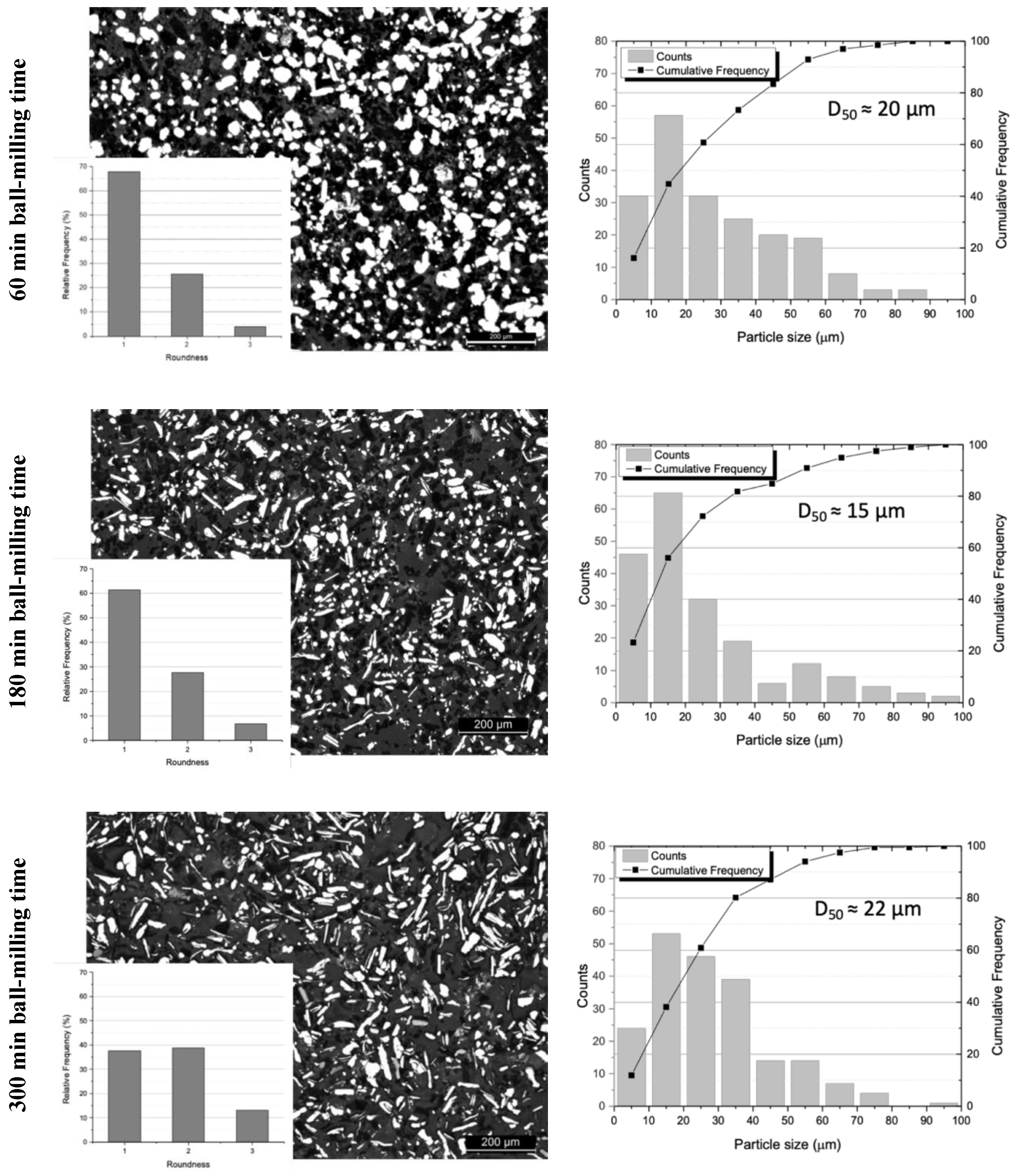
Figure 3.
SEM images of (a) as-received Ni powder, (b) Ni–CNTs ball-milled for 60 min with a detail of a particle with CNTs dispersed.
Figure 3.
SEM images of (a) as-received Ni powder, (b) Ni–CNTs ball-milled for 60 min with a detail of a particle with CNTs dispersed.

Figure 4.
OM images of the sintered Ni–CNTs in cross section (a–c) and SEM images of the fracture surface (d–f) after ball-milling for: (a and d) 60 min, (b and e) 180 min, and (c and f) 300 min.
Figure 4.
OM images of the sintered Ni–CNTs in cross section (a–c) and SEM images of the fracture surface (d–f) after ball-milling for: (a and d) 60 min, (b and e) 180 min, and (c and f) 300 min.
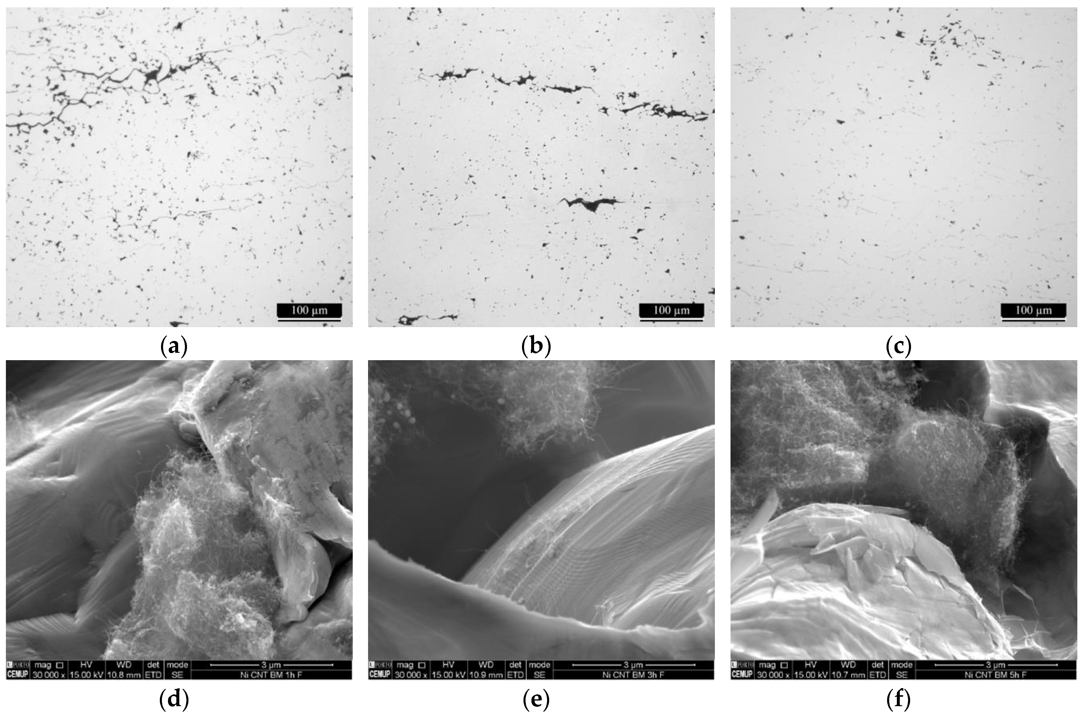
Figure 5.
Inverse pole figure (IPF) maps and second-neighbor kernel average misorientation (KAM) maps of sintered Ni–CNTs, using ball-milling for 60, 180, and 300 min. BM: ball-milled.
Figure 5.
Inverse pole figure (IPF) maps and second-neighbor kernel average misorientation (KAM) maps of sintered Ni–CNTs, using ball-milling for 60, 180, and 300 min. BM: ball-milled.
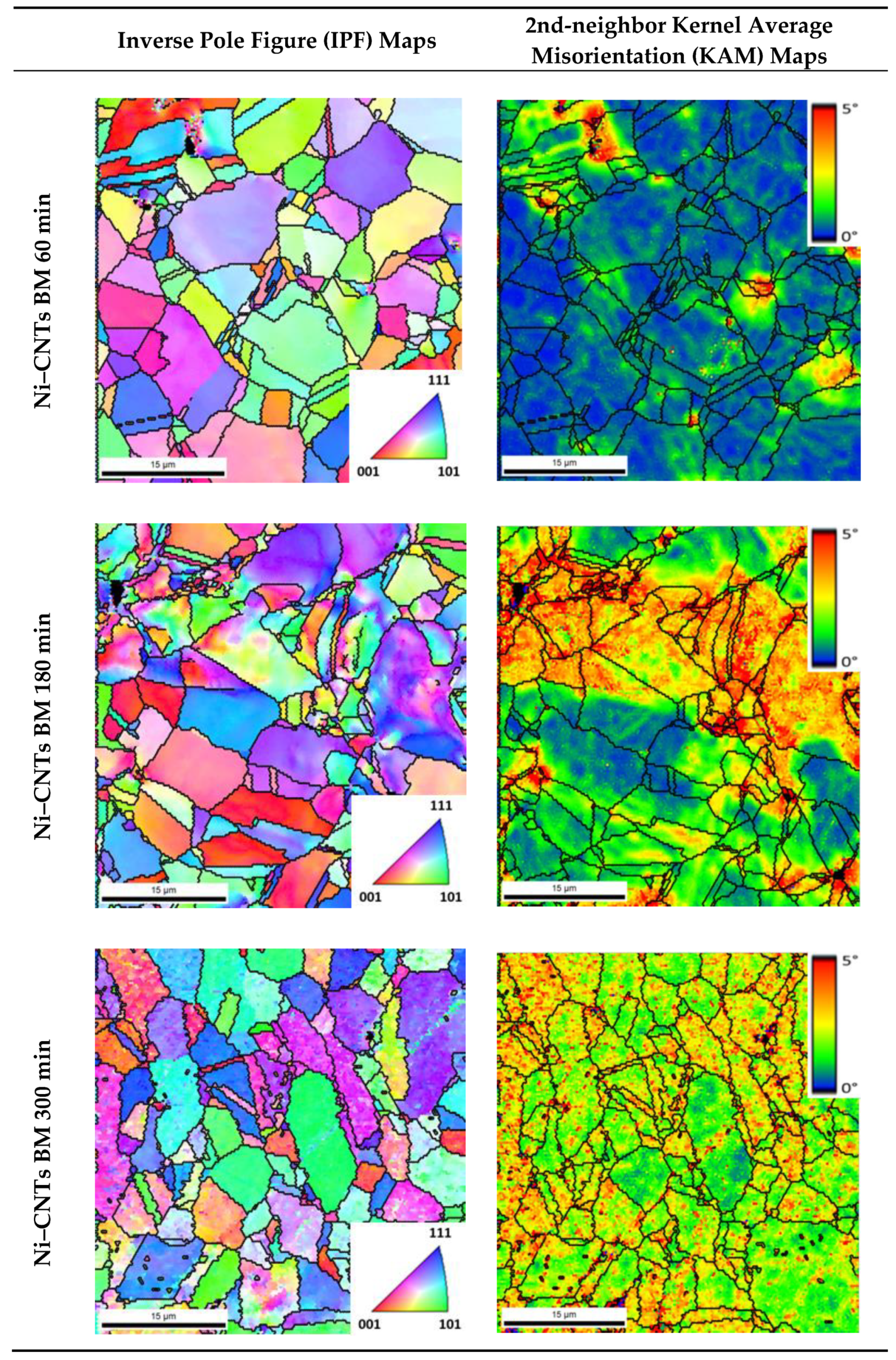
Figure 6.
(a,c) IPF maps (on the left with detail in the center) and (b,d) grain orientation spread (GOS) maps (on the right) of samples ball-milled for 180 min: (a,b) sintered Ni; (c,d) sintered Ni–CNTs.
Figure 6.
(a,c) IPF maps (on the left with detail in the center) and (b,d) grain orientation spread (GOS) maps (on the right) of samples ball-milled for 180 min: (a,b) sintered Ni; (c,d) sintered Ni–CNTs.
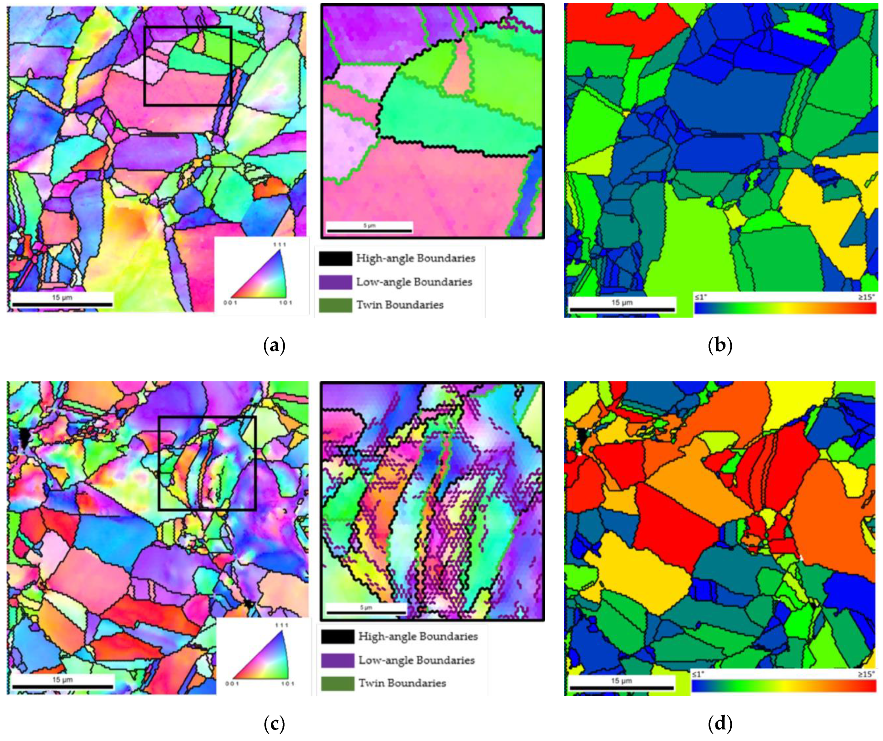
Figure 7.
Hardness distribution maps (HV 0.05) of (a) Ni and (b) Ni–CNT, processed by 180 min of ball-milling.
Figure 7.
Hardness distribution maps (HV 0.05) of (a) Ni and (b) Ni–CNT, processed by 180 min of ball-milling.


Table 1.
Percentage of porosity and CNT agglomerates of sintered samples for different ball-milling times.
Table 1.
Percentage of porosity and CNT agglomerates of sintered samples for different ball-milling times.
| Samples | Ball-Milling Time | ||
|---|---|---|---|
| 60 min | 180 min | 300 min | |
| Ni | 2.0% | 1.3% | 0.4% |
| Ni–CNTs | 3.7% | 2.4% | 1.0% |
Table 2.
The average grain size of sintered samples for different ball-milling times.
| Samples | Ball-Milling Time | ||
|---|---|---|---|
| 60 min | 180 min | 300 min | |
| Ni | 12.3 ± 7.9 µm | 10.2 ± 5.4 µm | 8.0 ± 4.6 µm |
| Ni–CNTs | 10.5 ± 5.2 µm | 8.9 ± 5.0 µm | 6.6 ± 4.2 µm |
© 2019 by the authors. Licensee MDPI, Basel, Switzerland. This article is an open access article distributed under the terms and conditions of the Creative Commons Attribution (CC BY) license (http://creativecommons.org/licenses/by/4.0/).
Share and Cite
MDPI and ACS Style
Carneiro, Í.; Viana, F.; Vieira, M.F.; Valdemar Fernandes, J.; Simões, S. Characterization of Ni–CNTs Nanocomposites Produced by Ball-Milling. Metals 2020, 10, 2. https://doi.org/10.3390/met10010002
AMA Style
Carneiro Í, Viana F, Vieira MF, Valdemar Fernandes J, Simões S. Characterization of Ni–CNTs Nanocomposites Produced by Ball-Milling. Metals. 2020; 10(1):2. https://doi.org/10.3390/met10010002
Chicago/Turabian StyleCarneiro, Íris, Filomena Viana, Manuel F. Vieira, José Valdemar Fernandes, and Sónia Simões. 2020. "Characterization of Ni–CNTs Nanocomposites Produced by Ball-Milling" Metals 10, no. 1: 2. https://doi.org/10.3390/met10010002
Note that from the first issue of 2016, this journal uses article numbers instead of page numbers. See further details here.