Effects of Solution Treatment on Laser Welding of Ti–6Al–4V Alloy Plate Produced through Wire Arc Additive Manufacturing

Jiangxi Key Laboratory of Forming and Joining Technology for Aerospace Components, Nanchang Hangkong University, Nanchang 330063, China
*
Author to whom correspondence should be addressed.
†
These authors contributed equally to this work.
Metals 2020, 10(10), 1310; https://doi.org/10.3390/met10101310
Submission received: 26 August 2020
/
Revised: 27 September 2020
/
Accepted: 28 September 2020
/
Published: 30 September 2020
(This article belongs to the Special Issue Laser Welding Innovations)
Abstract
:Laser beam welding (LBW) had been successfully applied to the welding of Ti–6Al–4V plates by wire arc additive manufacturing. The effects of solution treatment on microstructure, tensile properties, and microhardness after LBW in different deposition directions were studied. When the wire speeding was 3 m/min and travel speed was 0.36 m/min, the difference in mechanical properties was related to the anisotropy of the microstructure. The long columnar grain along the building direction could provide an α path with a large aspect ratio and high elongation. More grain boundaries are present along the scanning direction than in others, showing high strength. The microstructure of the as-deposited condition mainly consists of coarse prior-β grains, partial basket-weave structure, and numerous martensite α′ phase. In LBW without solution treatment, the microstructure of the welds mainly consists of a large amount of martensite α′ and a small amount of basket-weave structure. The weld had high strength and hardness. The tensile strength was between 930 and 970 MPa. The hardness was between 415 and 456 HV. The elongation ranged from 5% to 7%. Afterwards, the temperature was maintained at 870 °C for 2 h, cooled to 600 °C in the furnace for 1 h, and finally air cooled to room temperature. The martensite α′ was almost completely transformed into platelet α. The microstructure of the welds mainly consists of partial β grains, thimbleful martensite α′, and a large of α path. The strength and hardness of the welds were reduced. The tensile strength is between 910 and 950 MPa. The hardness was between 398 and 445 HV. However, the elongation was significantly improved, and the elongation ranged from 10% to 12%.
1. Introduction
Ti-6Al-4V alloy has the advantages of low density (4.44 g/cm3), high specific strength (sb/g = 23.5, alloy steel: sb/g ≤ 18), corrosion resistance and heat resistance, non-magnetism, and good biocompatibility [1,2,3,4,5,6]. It consists of the HCP-α phase and the BCC-β phase. With a strong influence on the transformation temperature, and based on their effect on the transformation temperature, the alloying elements are separated into two groups, α- and β-stabilizers [7]. Al is a strong α-stabilizer; with increasing solute content, it increases the transformation temperature. Sufficient concentration of β-stabilizing elements, such as vanadium (V), lowers the transformation temperature, thereby stabilizing the β-phase down to room temperature. For Ti–6Al–4V, the β phase is distributed between the α phase and contains approximately 6% Al for α stabilization and 4% V for β stabilization, leading to the good weldability of the Ti–6Al–4V alloy [8,9]. Thus, it has been widely used in aerospace, biomedicine, petrochemical, and other fields.
Wire and arc additive manufacturing (WAAM) is attracting considerable attention due to its low cost, high efficiency, and ability to rapidly manufacture large components [3,10]. WAAM is a good solution to low laser deposition efficiency and is not limited by vacuum chamber in contrast to electron beam additive manufacturing. In manufacturing Ti–6Al–4V alloy by WAAM, due to a large amount of thermal input, the columnar β grains and grain size in WAAM-ed wall usually increase with increasing layers. These coarse columnar β grains are epitaxially grown by multilayer deposition and reach several millimeters; thus, they have strong anisotropy [6,11,12,13,14,15,16]. For manufacturing large components, thermal cycling and cooling during WAAM generate large internal stress, leading to deformation and fracture, thereby affecting the performance of the parts [17]. It is a feasible method for manufacturing large parts with reduced internal stress by separately manufacturing parts through additive manufacturing (AM) and jointing them together by welding [18]. Wang et al. [19] proposed an approach for fabricating the part as a hybrid component by combining the parts of AM with that of the economical conventional processing methods. Electron beam melted (EBM)-built Ti–6Al–4V plates were joint to wrought counterparts through laser welding. The result indicated that laser welding is an effective method of fabricating large-scale components by joint EBM-built metal to its wrought form. Sun et al. [18] melted Ti–6Al–4V to wrought Ti–6Al–4V through laser welding of electron beam. The investigation suggests that laser welding is an effective method to fabricate large-scale components by joint EBM-built metal to its wrought form and provide sufficient tensile properties. Chen et al. [20] individually fabricated two titanium alloy thick plates (Ti: Base, Al: 6.5%, Mo: 3.5%, Zr: 1.5%, Si: 0.3% in wt.%) by laser additive manufacturing and then jointed them together through EBW. Finally, the joint was successfully obtained without defects.
In the current study, a WAAM-ed Ti–6Al–4V plate was welded by laser welding and solution treatment, and the effect of solution treatment on the anisotropy of WAAM-ed Ti–6Al–4V was determined by studying the microstructure and mechanical properties of the product. This work aimed to provide a theoretical basis for connecting the reliability of WAAM-ed Ti–6Al–4V and expanding the applications of laser welding technology.
2. Materials and Methods
A Ti–6Al–4V wall was produced via additive manufacturing using a CMT TPS-2700 welding machine (Fronius International GmbH, Pettenbach, Austria) supplied by Fronius. A 1 mm-diameter Ti–6Al–4V wire AM was used on the Ti–6Al–4V substrate (length: 200 mm, width: 80 mm, height: 3 mm). The WAAM-ed parameters were as follows: U (9.8 V), I (83 A), travel speed (0.36 m/min), wire feeding speed (3.0 m/min), air flow (15 L/min), number of AM layers reaching 25, and inter-layer cooling time of 120 s. The composition of wire and substrate are listed in Table 1. The required plates were machined with a wire electric discharge machine (ChuangYuan Machine Tool co., Ltd., Taizhou, China). Then, 50 mm × 40 mm × 3 mm Ti–6Al–4V plates were obtained from the as-built wall. The selection mode is shown in Figure 1a,e. The plate surface was cleaned to remove grease and oil with acetone before welding.
A laser welding joint with welding direction parallel and vertical to the building direction is defined as building direction (BD) and scanning direction (SD), respectively. BD and SD were jointed via an IPG YLS-4000 laser welding equipment (IPG Photonics Corporation, Oxford, MA, USA). Before laser welding, an IPG-YLS-4000 fiber laser system was used during the pre-experiment on the Ti–6Al–4V alloy plate after AM. The test parameters are shown in Table 2. The macroscopic morphology of weld is shown in Figure 2. Excessive laser power in Group 1 and Group 2 led to the narrow weld bead, the low laser power in Group 4 led to the too wide weld bead, and the low power led to incomplete penetration in Group 5 and Group 6 and poor weld bead formation in Group 7. A 2 mm-wide and silvery weld bead can be produced under Group 3. The optimal welding parameters are as follows: 0 mm defocus distance, 1.5 kW laser power, and 2 m/min welding speed. Laser welding was performed in an argon-shielded environment and air flow was 15 L/min as shown in Figure 1c.
After welding, tensile samples were machined from each laser-welded plate, and the selection mode and size are shown in Figure 1b,d. Tensile testing was performed on an Instron universal testing machine (Model 8872, INSTRON Corporation, Boston, MA, USA) at a cross head speed 0.5 mm/min. The surfaces and cross-section were investigated via scanning electron microscopy (SEM) (Hitachi SU 1510, Tokyo, Japan) by using a Hitachi SU 1510 scanning electron microscope. A KSL-1100-M box furnace (Kejing Material Technology co., Ltd., Hefei, China), which can work under 1000 °C for a long time with temperature control accuracy of ±1 °C, was used for solution treatment. The heating rate was approximately 20 °C /min, and the cooling rate was approximately 4 °C /min. The samples were vacuum packaged with quartz tubes and placed into the furnace for solution treatment. As such, the oxidation of Ti–6Al–4V alloy during solution treatment can be prevented from affecting the mechanical properties or microstructure. The Ti–6Al–4V samples were solution treated at 870 °C for 2 h, furnace cooled, heated at 600 °C for 1 h, and air cooled to room temperature.
An SiC emery paper grind sample was used, and polishing paste (ZPOUN diamond co., Ltd., Shenzhen, China) was used to polish the sample. The Kroll reagent (1 mL 48% HF (FUYU Chemical GmbH, Tianjin, China), 3 mL 70% HNO3 (Jingen industrial limited company, Shanghai, China), 25 mL H2O) was used to etch the samples for microstructure. Then, the microstructures of the cross-section of the laser weld joints were observed under an optical microscope (Mingyu Instrument equipment co., Ltd., Shenzhen, China). Microhardness was measured using a QNESS 10A+ semiautomatic Vickers hardness tester (QATM GmbH, Salzburg, Austria) with a test load of 100 g and a dwell time of 10 s. Two more points near each point to average were obtained to ensure the accuracy of hardness value.
3. Results and Discussion
3.1. Micro and Macrostructure of Weld
Figure 3 shows the micro and macrostructure of the laser-welded joints in different directions. Through the optimized parameters in this study, the full penetration joint was obtained. As the laser welding speed was fast, the heat-affected zone (HAZ) was small, and the cooling speed was fast (>410 °C/s). The rapid cooling of the fusion zone (FZ) promoted the formation of the supersaturated martensite α′ with high energy storage [21].
The two zones in the HAZ are distinguished by the β phase transition temperature. The near-HAZ is approximately the area where the highest temperature is greater than Tβ and less than TL, and the far-HAZ is approximately the area where the highest temperature is less than Tβ but greater than the minimum temperature required for microstructure change. However, this temperature is difficult to define because additive manufacturing is a thermal cycle process. The microstructure of FZ is the columnar β grain epitaxial growth toward the center of the weld joint. The α phase stable element Al in the alloy may be evaporated by burning during welding, thereby hindering the transformation from the β phase to α′ phase to a certain extent [22]. The microstructure of HAZ is mainly composed of basket-weave, partial martensite α′, and residual β phase. The fusion zone (FZ) is the zone where the temperature exceeds the TL, and the fusion line separates FZ from HAZ. However, determining this boundary is difficult because of the numerous coarse β columnar grains in this area in the WAAM titanium alloy. The Ti–6Al–4V alloy manufactured by WAAM is mainly composed of a large number of α laths and martensite α′ phase as shown in Figure 3a (a5). Some β columnar grains are present at the bottom-FZ, in which the basket-weave structure and a large number of martensite α′ phases coexist as shown in Figure 3a (a3). The middle-FZ is mainly composed of martensite α′ and some basket-weave as shown in Figure 3a (a1). The martensite α′ content is also different due to the different distance from near-HAZ and far-HAZ to FZ in Figure 3a (a2 and a4).
As for the BD + BD samples, the martensite α′ content was obviously reduced as shown in Figure 3b (b5),c (c5). The near-HAZ of BD + BD sample is similar to SD + SD and mainly composed of a large number of martensite α′ and some basket weave as shown in Figure 3b (b1). The SD + BD sample was mainly composed of some martensite α′ and a large number of basket weave as shown in Figure 3c (c3). In the far-HAZ of BD sides, only a small amount of martensite α′ was present and was mainly composed of basket weave structure as shown in Figure 3b (b2),c (c2). Compared with the top-FZ, the bottom-FZ had more martensite α′, indicating that the bottom of the joint had a higher cooling rate than the top as shown in Figure 3b (b4),c (c4). In the bottom-FZ, the acicular martensite α′ orientation in the columnar β grains was different and chaotic, and the large primary martensite α′ phase and the small secondary martensite α′ phase coexist as shown in Figure 3c (c4).
Figure 4 shows the high magnification of martensite α′ structure from the SD + BD sample. The high temperature of welding plays an important role in the heat treatment of HAZ, and the martensite α′ precipitation in near-HAZ became extremely fine α in Figure 4b. Only the weld still had a large amount of martensite α′ as shown in Figure 4a. The Far-HAZ has many platelet α and a small amount of martensite α′. The original platelet α of Far-HAZ was coarsened and αs was formed after subjected to high temperature as shown in Figure 4f.
3.2. Post Welding Solution Treatment
The microstructure boundary of the joint after solution treatment is easy to observe. Martensitic α′ phase with high energy storage exists in FZ, HAZ, and BM before solution treatment. The main function of the solution treatment is to homogenize α phases with different morphologies generated during AM. It can promote the decomposition of metastable phase produced during solution treatment and result in a strengthening effect. After solution treatment, the martensite α′, which had not been precipitated in time due to the rapid cooling rate, was transformed into α phase. Figure 5a shows that the base materials (BM) are all SD, and the joint structure is approximately symmetrically distributed along the center line. After the acicular martensite α′ phase reaches a certain temperature (~800 °C), the α platelet begins to precipitate, and the primary α platelet continues to grow when heated, resulting in the decrease in aspect ratio. Compared with the top-FZ, Bottom-FZ has finer and longer platelet α, which indicates that the bottom of the joint has a higher cooling rate than the top before solution treatment. After solution treatment, αGB and α colonies began to precipitate on β grain boundaries in the BM (Figure 5a (a5)). The bottom-FZ had a faster cooling rate than the top-FZ; thus, the bottom-FZ had a finer and longer platelet α as shown in Figure 5a (a1 and a3). The difference between near-HAZ and far-HAZ was not remarkable, and showed typical basket weave organization in Figure 5a (a2 and a4). Figure 5b shows the macrostructure of BD + BD sample. After solution treatment, a large martensite α′ precipitated platelet α and αs in far-HAZ and near-HAZ in Figure 5b (b2 and b3). Compared with the other zones, the bottom-FZ had more chaotic platelet α as shown in Figure 5b (b4).
The microstructure of the SD + BD samples was obviously different from that of SD + SD (Figure 5a). The acicular martensite α′ orientation in the near-HAZ and far-HAZ was different and cluttered, and the larger primary martensite α′ phase and the smaller secondary martensite α′ phase coexist in Figure 5c (c2 and c4). The HAZ on the SD side became small, which may be caused by the different growth states of columnar grains in two different directions.
Figure 6 shows the high magnification of the martensite α′ structure from SD + BD sample after solution treatment. The acicular martensite α′ in the welds was completely precipitated, and α phase began to precipitate on the prior-β grain boundary. The platelet α of HAZ increased further, and the contour became clear and could be calculated. The platelet α widths of FZ, near-HAZ, and far-HAZ were 1.14 ± 0.11, 1.59 ± 0.16, and 1.80 ± 0.17 μm, respectively.
3.3. Tensile Properties
Figure 7 shows that the critically resolved shear stress is the component of shear stress on a certain slip plane, resolved in the direction of slip, which is required to cause slip on a certain colony [23]. The red box shows the maximum shear stresses τ at a 45° to the principal stress σ (the maximum shear stresses appear in pairs).
Colonies could control the whole prior-β grain in some areas, thus enabling dislocations to move for long distances because the size of colonies determines the effective slippage length [24]. However, the size of α colonies depends on the cooling rate of the β phase field and the grain size of β that limits the maximum α colonies size. The differences in elongation and strength in the scanning and building directions can be attributed to coarse β columnar grains. The Stroh pile-up model proposes neighboring strong and weak grains, where a strong (hard) grain is a grain unfavorably oriented for slip (such as β grain) and a weak (soft) grain is a grain favorably oriented for slip (such as platelet α) [25,26]. For joints of the SD side, the strength resulting from the prior-β grain boundaries is higher than that from the β grains, leading to the β grain boundary separation that requires a greater tensile force than that of the BD sample [27]. At the same time, the slip plane is almost perpendicular to the maximum principal stress σ. So, the strength of the SD + SD specimen is higher than that of the BD + BD. Figure 7 shows that as for the joints of the SD + BD sample, the SD side has excellent tensile strength and the BD side has good elongation, with remarkable strength and ductility. The mechanical properties obtained are shown in Table 3. After solution treatment, the tensile strength and elongation exceeded ASTM B381-13 standard, and SD + BD had excellent overall properties, indicating that proper solution treatment could improve the mechanical properties of the laser-welded WAAM-ed Ti–6Al–4V plate.
The index of plane anisotropy (IPA) could be used to compare the properties of anisotropy in two states. Anisotropy is expressed as follows:
where YSBD is the yield strength of the longitudinal, YS45° is specimen axis at 45° direction, and YSSD is the yield strength of the transverse. For the tensile property test results in the directions of the longitudinal, 45° and transverse, Formula (1) could be simplified as follows [28]:
The average yield and ultimate tensile strengths are higher in the longitudinal direction than in the transverse direction [11]. According to Formula (2), the smaller the YSBD, the smaller the anisotropy of the sample.
Figure 8 shows the fracture morphology of tensile samples before solution treatment. The microhardness and strength of titanium alloy generally follow the order α′ > α > β [29]. All the samples are fractured at the FZ. A void is one of the most common and harmful defects in laser welding of titanium alloy that easily causes stress concentration and reduces the comprehensive performance of the weld. Most of the voids are distributed at the interfaces between the FZ and HAZ [30]. In laser welding, the great temperature gradient inside the weld pool prevents the protective gas caught in the weld pool after rapid solidification to escape, thus forming pores at the bottom of the weld pool [31], as shown in Figure 8b. The fractures are flat from the macro, and shallow torn edges are visible under SEM, indicating instantaneous fracture (Figure 8c). A large number of spalling martensite α′ structures and river pattern are present at the fracture surface as shown in Figure 8d,e. A large amount of martensite α′ was the cause of brittleness of the weld. However, partial dimples were still observed as shown in Figure 8f, suggesting that it was a ductile-brittle mixed fracture.
Figure 9 shows the fracture morphology of the tensile specimen after solution treatment. Martensite is almost completely transformed into α phase, and only a small amount of martensite could be observed on the fracture surface as shown in Figure 9d. The deep dimples and torn edges show the samples were remarkably elongated due to the increased of platelet α content, indicating that the fracture mode was ductile fracture dominated by α phase in Figure 9a,b. All cross through columnar β grains and finally break along platelet α. After solution treatment, the samples were all fractured in the BM, which was mainly due to the acicular martensite α′ in the FZ that transformed into fine α lath and αs. The α lath in the BM was coarsened, and the aspect ratio was reduced, resulting in the final strength being inferior to that in the FZ.
3.4. Microhardness
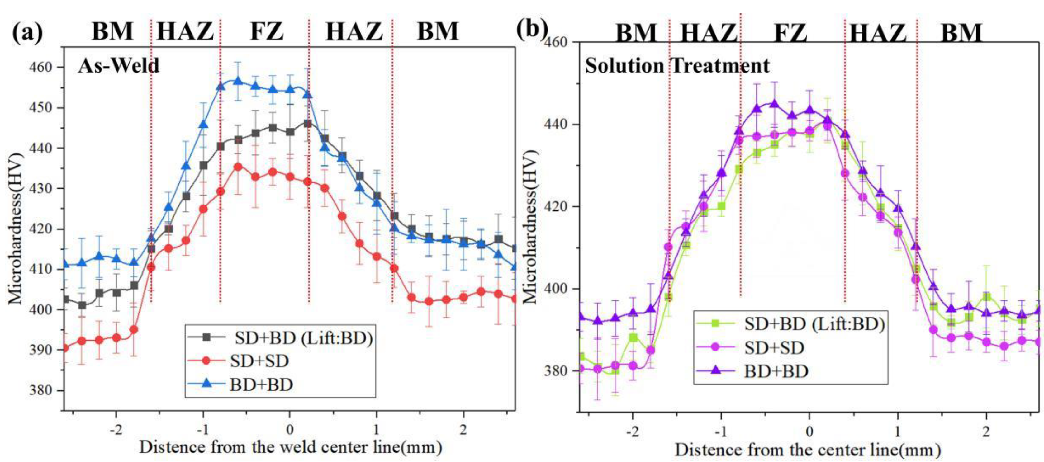
The microhardness profiles of the Ti–6Al–4V laser welding samples following the welding-related treatments are shown in Figure 10. The distribution range of the hardness was consistent with the three regions (i.e., BM, HAZ, and FZ) that featured distinct microstructures, with FZ as the hardest region and hardness decreasing rapidly as the distance from the FZ increased in all conditions. The BD + BD sample with no solution treatment showed the highest hardness of 456.58 ± 5.6 HV in FZ. The hardness of SD + SD and SD + BD sample FZ were 435.44 ± 5.87 HV and 446.18 ± 4.54 HV, respectively. After solution treatment, the hardness of samples decreased slightly because the brittle martensite α′ content was reduced. The mean hardness values of SD + SD, SD + BD, and BD + BD were 439.75 ± 2.85, 441.24 ± 4.68, and 444.89 ± 2.98 HV, respectively.
4. Conclusions
This study first jointed the plates in different directions of WAAM-ed Ti–6Al–4V plates via laser welding to overcome the size limitation issue. A full-density joint was successfully produced through laser welding. The effects of solution treatment on the microstructure and mechanical properties of samples in different welding directions were systematically studied. The major conclusions of the present study can be summarized as follows:
- (1)
- Rapid cooling caused shear deformation of the β phase and formed a large number of acicular martensite α′. As the FZ depth increased, acicular α′ became finer and denser due to the increased cooling rate.
- (2)
- The post welding solution treatment promoted the decomposition of the metastable phase produced, and a large martensite α′ phase transformed into platelet α. The decreased martensite α′ content led to a slight decrease in tensile strength and microhardness, but elongation was significantly improved.
- (3)
- The welds of samples without solution treatment were filled with a large amount of martensite α′. Solution treatment made the structure uniform, and the outline of weld clear. FZ, HAZ, and BM were composed of platelet α with different aspect ratios, which all showed a typical basket-weave structure morphology.
Author Contributions
Formal analysis, Y.C. and M.X.; methodology, M.X.; writing—original draft preparation, M.X.; writing—review and editing, Y.C. and T.Z.; funding acquisition, Y.C.; data curation, H.D. and D.J.; conceptualization, Y.C. All authors have read and agreed to the published version of the manuscript.
Funding
This paper was supported by the National Defense Basic Research Program grant number JCKY2018401C003; Key Research and Development Project of Jiangxi Province grant number 20192BBH80018; Jiangxi Distinguished Young Scholars grant number 2018ACB21016; Jiangxi Advantageous Scientific and Technological Innovation Team grant number 20171BCB24007.
Conflicts of Interest
The authors declare no conflict of interest.
References
- Zhang, X.; Li, L.; Lei, Z.; Chen, Y. Study on welding characteristics of combining laser welding and resistance seam welding joined Ti-6Al-4V lap joints. Pac. Int. Conf. Appl. Lasers Opt. 2008, 2008, 341. [Google Scholar]
- Fomin, F.; Froend, M.; Ventzke, V.; Alvarez, P.; Bauer, S.; Kashaev, N. Correction to: Metallurgical aspects of joining commercially pure titanium to Ti-6Al-4V alloy in a T-joint configuration by laser beam welding. Int. J. Adv. Manuf. Technol. 2018, 97, 2019–2031. [Google Scholar] [CrossRef] [Green Version]
- Mcandrew, A.R.; Rosales, M.A.; Colegrove, P.A.; Hönnige, J.R.; Ho, A.; Fayolle, R.; Eyitayo, K.; Stan, I.; Sukrongpang, P.; Crochemore, A.; et al. Interpass rolling of ti-6al-4v wire+arc additively manufactured features for microstructural refinement. Addit. Manuf. 2018, 21, 340–349. [Google Scholar] [CrossRef]
- Lei, R.; Xiao, W.; Ma, C.; Zheng, R.; Zhou, L. Development of a high strength and high ductility near β-ti alloy with twinning induced plasticity effect. Scr. Mater. 2018, 156, 47–50. [Google Scholar]
- Wang, W.; Huang, R.; Zhao, Y.; Liu, H.; Huang, C.; Yang, X.; Shan, Y.; Zhao, X.Q.; Li, L. Adjustable zero thermal expansion in Ti alloys at cryogenic temperature. J. Alloys Compd. 2018, 740, 47–51. [Google Scholar] [CrossRef]
- Tsai, T.J.; Wang, L.M. Improved mechanical properties of Ti–6Al–4V alloy by electron beam welding process plus annealing treatments and its microstructural evolution. Mater. Des. 2014, 60, 587–598. [Google Scholar] [CrossRef]
- Leyens, C.; Peters, M. Titanium and Titanium Alloys: Fundamentals and Applications; DLR: Dresden, Germany, 2003. [Google Scholar]
- Saresh, N.; Pillai, M.G.; Mathew, J. Investigations into the effects of electron beam welding on thick Ti–6Al–4V titanium alloy. J. Mater. Process. Technol. 2007, 192–193, 83–88. [Google Scholar] [CrossRef]
- Meshram, S.D.; Mohandas, T. A comparative evaluation of friction and electron beam welds of near-α titanium alloy. Mater. Des. 2010, 31, 2245–2252. [Google Scholar] [CrossRef]
- Williams, S.W.; Martina, F.; Addison, A.C.; Ding, J.; Pardal, G.; Colegrove, P.A. Wire + Arc Additive Manufacturing. Mater. Sci. Technol. 2016, 32, 641–647. [Google Scholar] [CrossRef] [Green Version]
- Wang, F.; Williams, S.W.; Colegrove, P.A.; Antonysamy, A.A. Microstructure and Mechanical Properties of Wire and Arc Additive Manufactured Ti-6Al-4V. Metall. Mater. Trans. A 2013, 44, 968–977. [Google Scholar] [CrossRef]
- Wang, F.; Williams, S.W.; Rush, M.T. Morphology investigation on direct current pulsed gas tungsten arc welded additive layer manufactured Ti6Al4V alloy. Int. J. Adv. Manuf. Technol. 2011, 57, 597–603. [Google Scholar] [CrossRef] [Green Version]
- Qian, M.; Xu, W.; Brandt, M.; Tang, H.P. Additive manufacturing and postprocessing of Ti-6Al-4V for superior mechanical properties. MRS Bull. 2016, 41, 775–784. [Google Scholar] [CrossRef] [Green Version]
- Sun, Y.Y.; Gulizia, S.; Fraser, D.; Oh, C.H.; Lu, S.L.; Qian, M. Layer Additive Production or Manufacturing of Thick Sections of Ti-6Al-4V by Selective Electron Beam Melting (SEBM). JOM 2017, 69, 1836–1843. [Google Scholar] [CrossRef]
- Albermani, S.S.; Blackmore, M.L.; Zhang, W.; Todd, I. The Origin of Microstructural Diversity, Texture, and Mechanical Properties in Electron Beam Melted Ti-6Al-4V. Metall. Mater. Trans. A 2010, 41, 3422–3434. [Google Scholar] [CrossRef]
- Wang, P.; Tan, X.; Nai, M.L.S.; Tor, S.B.; Wei, J. Spatial and geometrical-based characterization of microstructure and microhardness for an electron beam melted Ti–6Al–4V component. Mater. Des. 2016, 95, 287–295. [Google Scholar] [CrossRef]
- Wang, H.; Zhang, S.; Wang, X. Progress and Challenges of Laser Direct Manufacturing of Large Titanium Structural Components (Invited Paper). Chin. J. Lasers 2009, 36, 3204–3209. [Google Scholar] [CrossRef]
- Sun, Y.Y.; Wang, P.; Lu, S.L.; Li, L.Q.; Nai, M.L.S.; Wei, J. Laser welding of electron beam melted Ti-6Al-4V to wrought Ti-6Al-4V: Effect of welding angle on microstructure and mechanical properties. J. Alloys Compd. 2019, 782, 967–972. [Google Scholar] [CrossRef]
- Wang, P.; Nai, M.L.S.; Lu, S.; Bai, J.; Zhang, B.; Wei, J. Study of Direct Fabrication of a Ti-6Al-4V Impeller on a Wrought Ti-6Al-4V Plate by Electron Beam Melting. JOM 2017, 69, 2738–2744. [Google Scholar] [CrossRef]
- Chen, X.H.; Zhang, J.; Chen, X.; Cheng, X.; Huang, Z. Electron beam welding of laser additive manufacturing Ti–6.5Al–3.5Mo–1.5Zr–0.3Si titanium alloy thick plate. Vacuum 2018, 151, 116–121. [Google Scholar] [CrossRef]
- Bermingham, M.J.; Stjohn, D.H.; Krynen, J.; Tedman, J.S.; Dargusch, M.S. Promoting the columnar to equiaxed transition and grain refinement of titanium alloys during additive manufacturing. Acta Mater. 2019, 168, 261–274. [Google Scholar] [CrossRef]
- Bu, H.; Gao, Q.; Li, Y.; Wang, F.Y.; Zhan, X.H. Comparative Study on Microstructure and Aluminum Distribution Between Laser Beam Welding and Electron Beam Welding of Ti–6Al–4V Alloy Plates. Met. Mater. Int. 2020, 26, 1–13. [Google Scholar] [CrossRef]
- Gioacchino, F.D.; Fonseca, J.A. An experimental study of the polycrystalline plasticity of austenitic stainless steel. Int. J. Plast. 2015, 74, 92–109. [Google Scholar] [CrossRef]
- Lu, W.; Shi, Y.; Lei, Y.; Li, X. Effect of electron beam welding on the microstructures and mechanical properties of thick TC4-DT alloy. Mater. Des. 2012, 34, 509–515. [Google Scholar] [CrossRef]
- Whittaker, M.T.; Jones, P.; Pleydellpearce, C.; Rugg, D.; Williams, S. The effect of prestrain on low and high temperature creep in Ti834. Mater. Sci. Eng. A 2010, 527, 6683–6689. [Google Scholar] [CrossRef] [Green Version]
- Whittaker, M.T. Considerations in fatigue lifing of stress concentrations in textured titanium 6-4. Int. J. Fatigue 2011, 33, 1384–1391. [Google Scholar] [CrossRef] [Green Version]
- Shen, C.; Pan, Z.; Cuiuri, D.; Dong, B.; Li, H. In-depth study of the mechanical properties for Fe3Al based iron aluminide fabricated using the wire-arc additive manufacturing process. Mater. Sci. Eng. A 2016, 669, 118–126. [Google Scholar] [CrossRef]
- Banumathy, S.; Mandal, R.K.; Singh, A.K. Texture and anisotropy of a hot rolled Ti-16Nb alloy. J. Alloys Compd. 2010, 500, 325–338. [Google Scholar] [CrossRef]
- Zeng, L.; Bieler, T.R. Effects of working, heat treatment, and aging on microstructural evolution and crystallographic texture of α, α′ α″ and β phases inTi-6Al-4V wire. Mater. Sci. Eng. A 2015, 392, 403–414. [Google Scholar] [CrossRef]
- Yu, H.C.; Li, F.Z.; Yang, J.J.; Shao, J.J.; Wang, Z.M.; Zeng, X.Y. Investigation on laser welding of selective laser melted Ti-6Al-4V parts: Weldability, microstructure and mechanical properties. Mater. Sci. Eng. A 2018, 712, 20–27. [Google Scholar] [CrossRef]
- Kumar, C.; Das, M.; Paul, C.P.; Singh, B. Experimental investigation and metallo-graphic characterization of fiber laser beam welding of Ti-6Al-4V alloy using re-sponse surface method. Opt. Lasers Eng. 2017, 95, 52–68. [Google Scholar] [CrossRef]
Figure 1.
Schematic of sampling and welding. (a) YOZ direction, (b) configuration of the tensile specimens, (c) laser welding schematic, (d) selection of tensile sample and metallographic structure, and (e) macro of the Wire and arc additive manufacturing (WAAM)-ed Ti–6Al–4V alloy.
Figure 1.
Schematic of sampling and welding. (a) YOZ direction, (b) configuration of the tensile specimens, (c) laser welding schematic, (d) selection of tensile sample and metallographic structure, and (e) macro of the Wire and arc additive manufacturing (WAAM)-ed Ti–6Al–4V alloy.
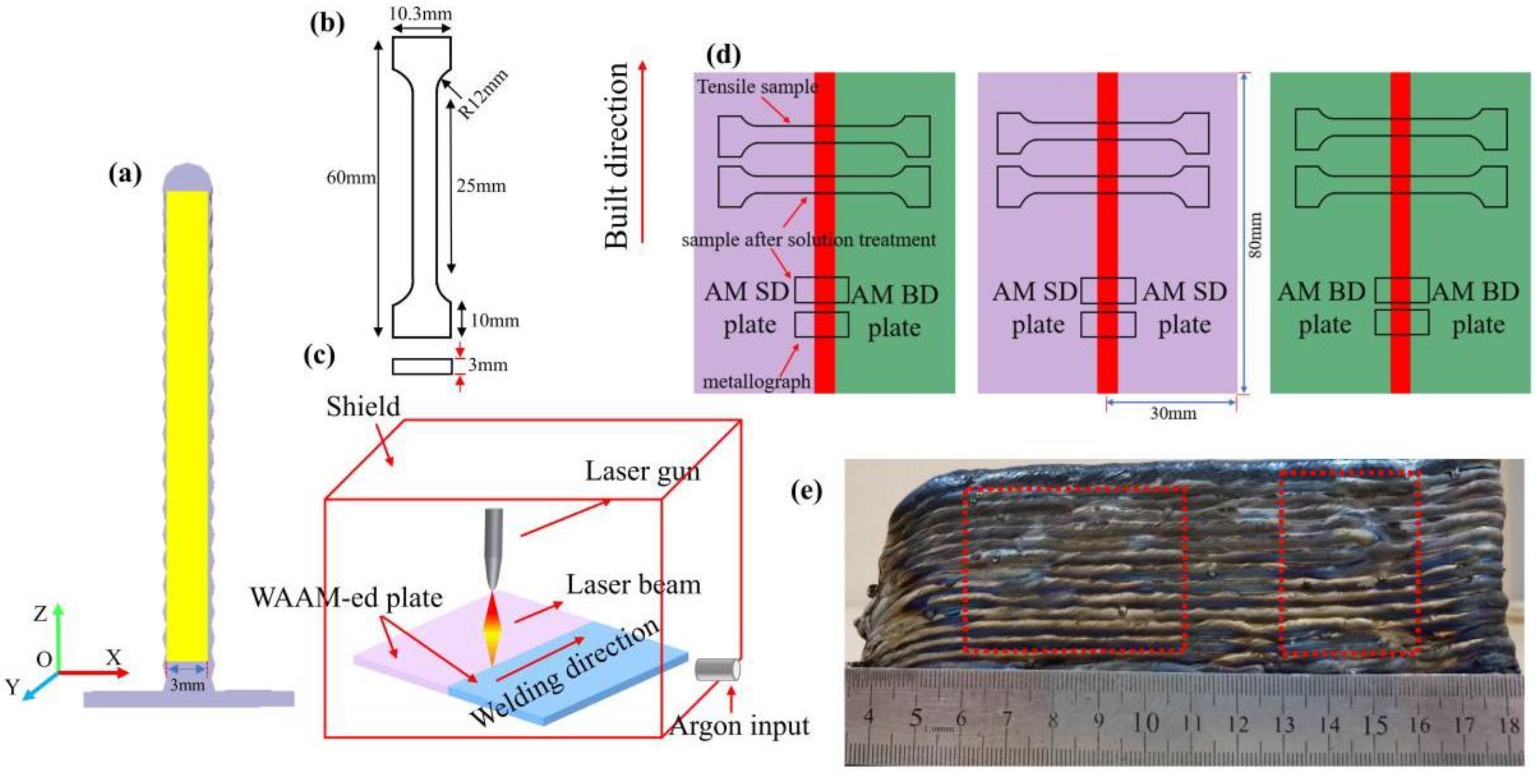
Figure 2.
Macro-morphology of welds with different parameters.
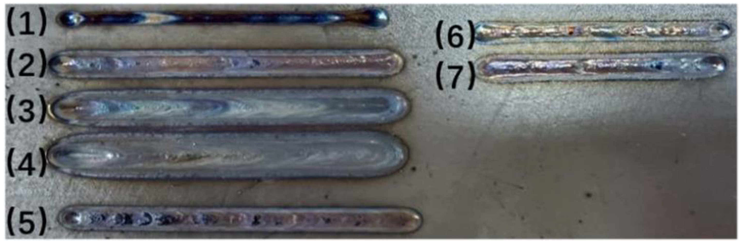
Figure 3.
No solution treatment. (a) scanning direction (SD) + SD sample, (b) building direction (BD) + BD sample (c) SD + BD sample.
Figure 3.
No solution treatment. (a) scanning direction (SD) + SD sample, (b) building direction (BD) + BD sample (c) SD + BD sample.
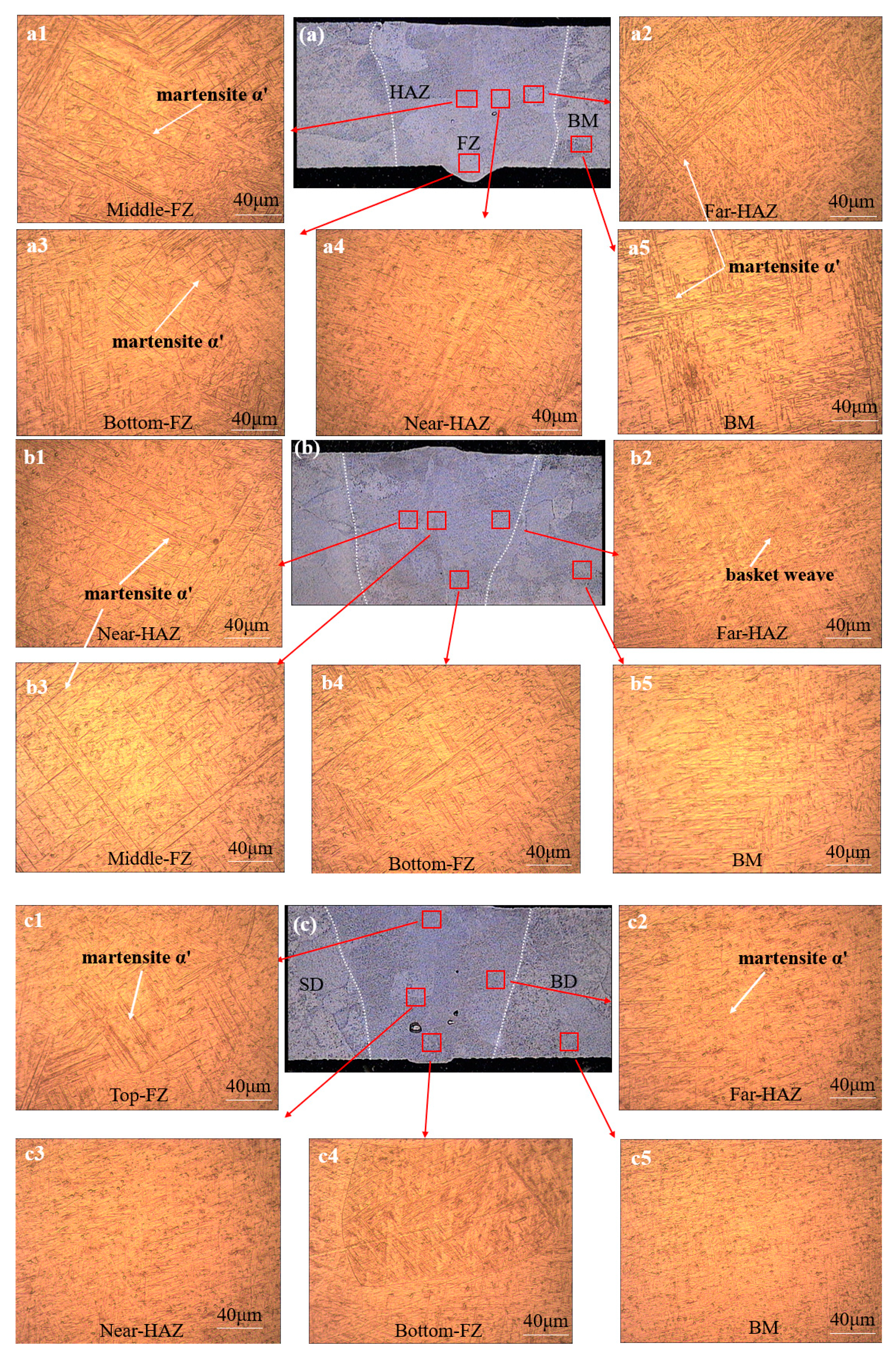
Figure 4.
SEM in SD + BD sample As-weld. (a) fusion zone (FZ), (b) Near-heat-affected zone (HAZ), (c) Far-HAZ, (d–f) are the enlarged pictures of (a–c), respectively.
Figure 4.
SEM in SD + BD sample As-weld. (a) fusion zone (FZ), (b) Near-heat-affected zone (HAZ), (c) Far-HAZ, (d–f) are the enlarged pictures of (a–c), respectively.
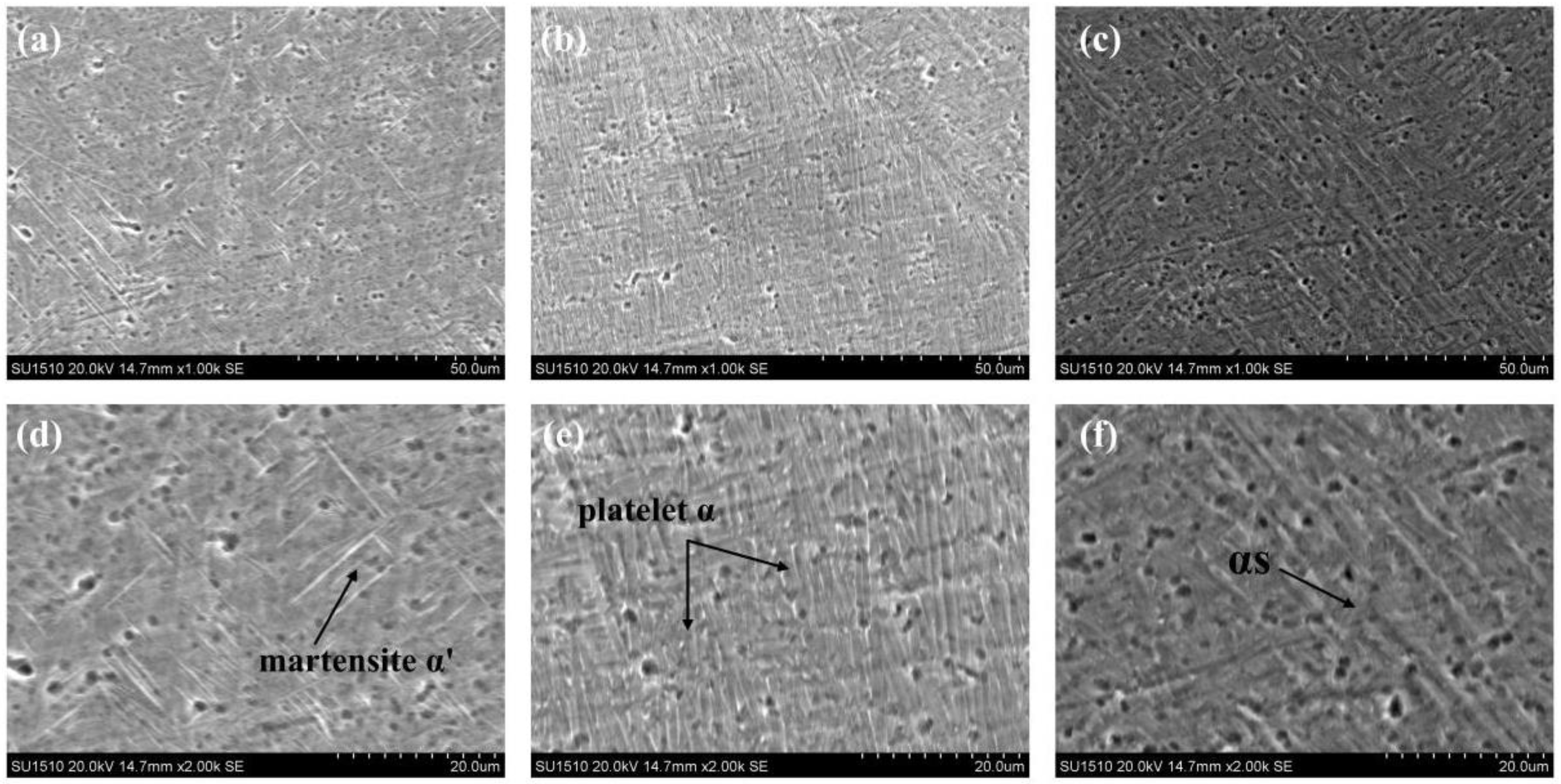
Figure 5.
Solution treatment. (a) SD + SD sample, (b) BD + BD sample, and (c) SD + BD sample.
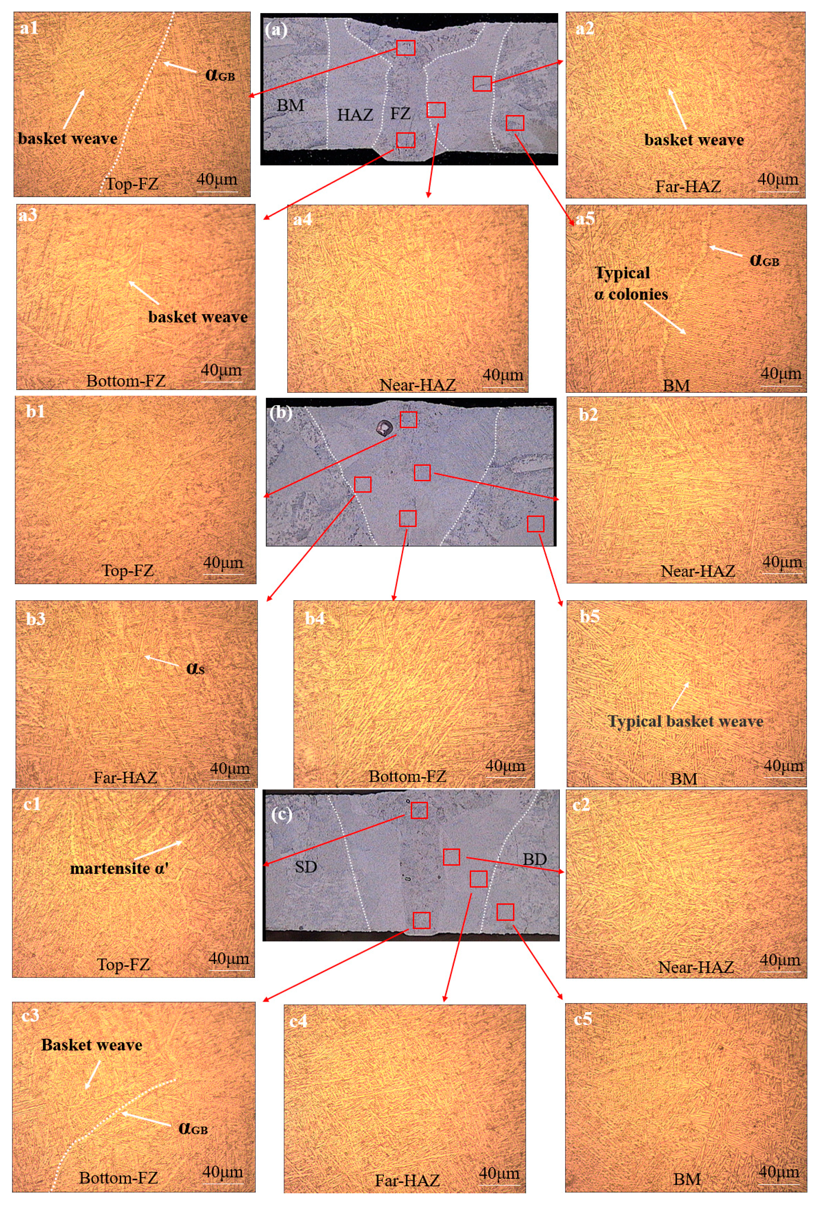
Figure 6.
SEM in SD + BD sample after solution treatment. (a) FZ, (b) near-HAZ, (c) far-HAZ, and (d), (e), and (f) are the enlarged images of (a–c), respectively.
Figure 6.
SEM in SD + BD sample after solution treatment. (a) FZ, (b) near-HAZ, (c) far-HAZ, and (d), (e), and (f) are the enlarged images of (a–c), respectively.
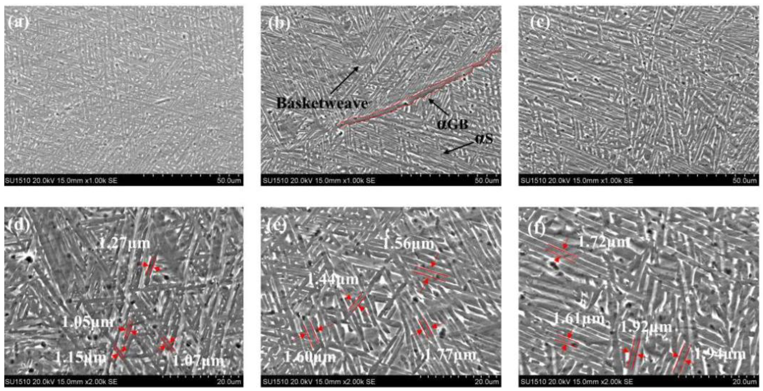
Figure 7.
Stress state of red boxes in the laser welding when subjected to uniaxial tension.
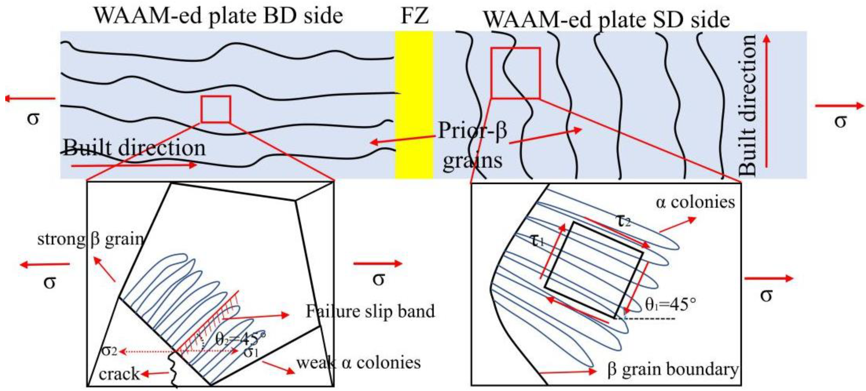
Figure 8.
Fracture morphology of the sample after solution treatment. (a,b) SD + SD, (c,d) BD + SD, (e,f) SD + BD.
Figure 8.
Fracture morphology of the sample after solution treatment. (a,b) SD + SD, (c,d) BD + SD, (e,f) SD + BD.
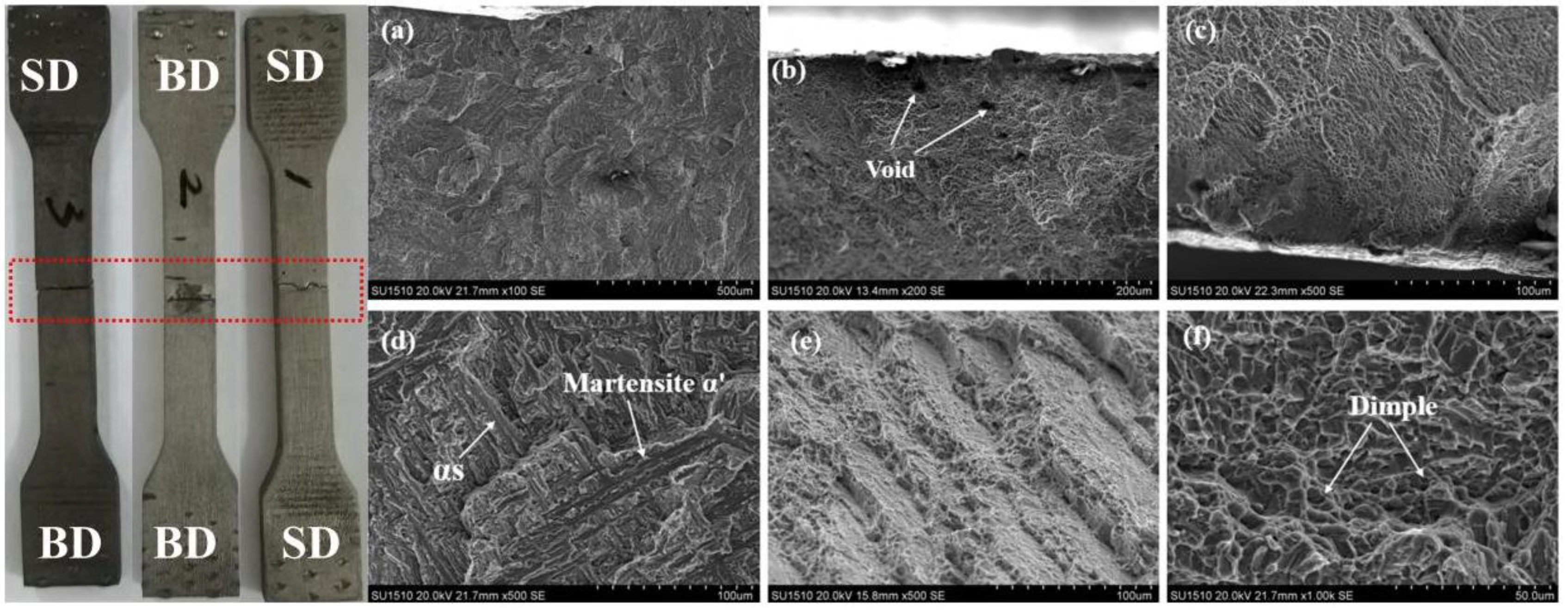
Figure 9.
Fracture morphology of the sample after solution treatment. (a,b) SD + BD, (c) BD + BD, (d) SD + SD, and (e,f) are the enlarged areas of BOX1 and BOX2, respectively.
Figure 9.
Fracture morphology of the sample after solution treatment. (a,b) SD + BD, (c) BD + BD, (d) SD + SD, and (e,f) are the enlarged areas of BOX1 and BOX2, respectively.

Figure 10.
Microhardness profiles of the Ti–6Al–4V laser welding samples (a) As–weld; (b) solution treatment.
Figure 10.
Microhardness profiles of the Ti–6Al–4V laser welding samples (a) As–weld; (b) solution treatment.

Table 1.
Main chemical constituents of the Ti–6Al–4V wire and substrate (wt.%).
| Category | Al | V | Fe | C | N | H | O | Ti |
|---|---|---|---|---|---|---|---|---|
| Wire | 6.05 | 4.00 | 0.15 | 0.02 | 0.01 | 0.003 | 0.018 | Bal. |
| Substrate | 6.10 | 3.90 | 0.15 | 0.08 | 0.05 | 0.015 | 0.02 | Bal. |
Table 2.
Laser welding process parameters.
| Group | Defocus Distance Δf/mm | Laser Power P/kW | Welding Speed V/(m/min) | Argon Shielded Q/(L/min) |
|---|---|---|---|---|
| 1 | 0 | 2.5 | 2 | 15 |
| 2 | 0 | 2 | 2 | 15 |
| 3 | 0 | 1.5 | 2 | 15 |
| 4 | 0 | 1 | 2 | 15 |
| 5 | 0 | 1 | 1.5 | 15 |
| 6 | 0 | 1 | 1 | 15 |
| 7 | 0 | 1.5 | 1 | 15 |
Table 3.
Room temperature tensile properties of laser welding WAAM-ed Ti–6Al–4V.
| Before Solution Treatment | Tensile Strength (MPA) | Elongation (%) | After Solution Treatment | Tensile Strength (MPA) | Elongation (%) |
|---|---|---|---|---|---|
| SD + SD | 970.2 ± 5 | 5.13 ± 0.82 | SD + SD | 948.9 ± 4 | 10.07 ± 0.77 |
| SD + BD | 966.8 ± 3 | 6.07 ± 0.75 | SD + BD | 924.8 ± 6 | 11.03 ± 2.62 |
| BD + BD | 933.6 ± 4 | 6.98 ± 0.83 | BD + BD | 911.6 ± 8 | 12.23 ± 1.22 |
| ASTM B381-13 | ≥895 | ≥10 | - | - | - |
© 2020 by the authors. Licensee MDPI, Basel, Switzerland. This article is an open access article distributed under the terms and conditions of the Creative Commons Attribution (CC BY) license (http://creativecommons.org/licenses/by/4.0/).
Share and Cite
MDPI and ACS Style
Xu, M.; Chen, Y.; Zhang, T.; Deng, H.; Ji, D. Effects of Solution Treatment on Laser Welding of Ti–6Al–4V Alloy Plate Produced through Wire Arc Additive Manufacturing. Metals 2020, 10, 1310. https://doi.org/10.3390/met10101310
AMA Style
Xu M, Chen Y, Zhang T, Deng H, Ji D. Effects of Solution Treatment on Laser Welding of Ti–6Al–4V Alloy Plate Produced through Wire Arc Additive Manufacturing. Metals. 2020; 10(10):1310. https://doi.org/10.3390/met10101310
Chicago/Turabian StyleXu, Mingfang, Yuhua Chen, Timing Zhang, Huaibo Deng, and Di Ji. 2020. "Effects of Solution Treatment on Laser Welding of Ti–6Al–4V Alloy Plate Produced through Wire Arc Additive Manufacturing" Metals 10, no. 10: 1310. https://doi.org/10.3390/met10101310
Note that from the first issue of 2016, this journal uses article numbers instead of page numbers. See further details here.