Influence of the Longitudinal Magnetic Field on the Formation of the Bead in Narrow Gap Gas Tungsten Arc Welding

School of Mechanical and Electrical Engineering, Wuhan Institute of Technology, Wuhan 430205, China
*
Author to whom correspondence should be addressed.
Metals 2020, 10(10), 1351; https://doi.org/10.3390/met10101351
Submission received: 12 September 2020
/
Revised: 29 September 2020
/
Accepted: 30 September 2020
/
Published: 9 October 2020
Abstract
:The oscillation arc assisted by an extra alternating longitudinal magnetic field (LMF) in narrow gap tungsten arc welding is proved to be effective in avoiding welding defects due to insufficient fusion at the side walls in joining thick wall plates. The behavior of the welding arc and molten pool under the LMF is simulated to reveal the influence of the LMF on the formation of a uniform penetration weld bead. A unified mathematical model was developed for the narrow gap tungsten arc welding including the plasma arc, molten pool, electrode, and their interactions. Under the LMF, the whole welding arc is deflected and oscillates between the two side walls. When the magnetic-field strength is larger than 6 mT, the axis of the arc deflects to the side wall; the maximum value of heat flux at the bottom decreases by one-half, and the maximum value at the side wall is increased by a factor of ten. On the other hand, under the LMF, the forces acting on the molten pool are changed; the fluid flow pattern is helpful to increase the heat transferred to the side walls. The model is validated by experimental results. Both the percentage deviations of the simulation weld penetration at the side wall and at the bottom from the experimental results are lower than 10%.
1. Introduction
Thick wall plates are widely applied in marine, energies, transport industries, and so on. The joining technology of them is a key factor influencing the manufacturing efficiency and stability. Narrow gap welding has a lower welding area compared with the normal welding technology, so the linear heat input and the plastic deformation along the thickness of the plate are small; it makes the residual stress and residual deformation small. Compared with the other joining technology, narrow gap welding has the advantages of low cost, small deformation, high efficiency, and so on; in addition, it has been the preferred method for the thick wall plates [1]. However, the swing amplitude of the welding arc is limited by the narrow gap, and it is difficult to heat the groove corner and groove side walls directly. So, a lack of penetration appears frequently at the weld bead.
Some solutions are proposed to prevent welding defects due to the lack of penetration. Wang et al. [2] developed a swing arc system in narrow gap gas metal arc welding, in which a motor with a hollow axis rotates the micro bent conductive rod, and the rod drives the arc to swing between the narrow gap. The swing arc process greatly improves the side wall penetration. Then, the authors optimized the welding parameters experimentally [3]. Xu et al. [4] developed a heat source model for the swing arc and investigated the characteristic of weld formation. Huang et al. [5] found that the swing hybrid TIG(tungsten inert gas arc weding)-MIG(metal-inert gas welding) technology can obtain enough side wall penetration. Guo et al. [6] applied the rotating arc technology to avoid a lack of penetration and pointed out it can remove the slag at the interlayer. Wei et al. [7] developed non-axisymmetric tungsten narrow gap tungsten arc welding, in which the heating of the rotating arc and the stirring action of the molten pool make a good shape weld. Cai et al. [8,9] combined the tandem technology to the narrow gap welding; a uniform fusion weld was obtained under appropriate welding parameters. In the above solutions, the motion path of the welding arc is changed mechanically, so the welding arc can heat the side wall directly, and the side wall penetration is increased significantly. However, the welding equipment is relatively complex, and many parameters are introduced.
An extra magnetic field is effective in regulating the arc welding process, and it has the advantages of easy operation and low cost [10]. Belous [11] first applied an alternating longitudinal magnetic field (LMF) in narrow gap welding to join titanium alloy and obtained no defect weld. Kang and Na [12] studied the characteristics of the welding arc and weld bead dimensions in narrow gap welding, and they optimized the magnetic and welding parameters. Sun et al. [13,14] developed a novel double magnetic pole system for narrow gap welding to produce more uniform magnetic-field lines [13,14,15]. Wang et al. [16] used the LMF in low-frequency pulse narrow gap welding; the distribution of arc pressure and heat is more reasonably between the bottom and side wall of the narrow groove. The present studies about LMF-assisted narrow gap gas tungsten arc welding (LMF-NG-GTAW) are mainly focused on the characteristics of the weld shape under different magnetic-field parameters and the welding equipment. The studies about the welds formation mechanism are still not enough.
When an extra magnetic field is applied to the arc welding, many physical fields will be changed, such as the current density, heat flux, and fluid flow [17,18,19], and all these factors have a critical influence on the weld formation. To better apply the LMF in NG-GTAW, it is essential to study the heating characteristics of the magnetically oscillation arc (MOA) and the fluid flow in the molten pool. In this paper, a 3D mathematical model is developed for the LMF-NG-GTAW, and the weld formation process is simulated. The model is validated by using the experimental data from references.
2. Mathematical Model
The schematic diagram of LMF-NG-GTAW is shown in Figure 1. In the narrow groove, the welding torch is fixed with the magnetic generator equipment. The wave of the excitation current flowing through the coils is shown in Figure 1c. The magnetic lines are parallel with the welding direction, and the Lorentz force is perpendicular to the welding direction. The Lorentz force drives the arc plasma oscillations between the narrow groove side walls, as shown in Figure 1b. In the LMF-NG-GTAW process, the transient plasma arc and the weld pool are not symmetrical, so a 3D mathematical model is needed. The model should consider the complicated physical processes, such as the arc burning, heat, and mass transfer in the weld pool, the melting and solidification of the work piece, and the coupling interaction between them.
2.1. Computational Domain
The simulation domain is shown in Figure 2. It includes the gas phase, electrode, arc column, weld pool, and solidus work piece. The shielding gas flows into the arc zone from the gas inlet ABEF and flows out from the outlets ABCD and EFGH; the welding arc burns between the electrode tip and the narrow welding groove. The weld pool is formed under the MOA, and then it is solidified into weld beads. The dimension of the work piece is 20 × 20 × 14 mm; the groove dimension is 20 × 10 × 9 mm. The origin coordinates are located at the axis of the electrode. The distribution of the LMF is not the study point in this paper, so the magnetic excitation equipment is not included in this model, and the distribution of the LMF is assumed as uniform. In the simulation domain, both the shielding gas and plasma arc are treated as a gas phase; the weld pool is set as liquid phase, and the work piece with a temperature lower than the melting point is also treated as a liquid phase but with a big viscosity.
2.2. Governing Equations
The main physical fields that appeared during the welding process are calculated; they are the temperature field, fluid flow, and the electromagnetic field. The magnetohydrodynamics conservation equations are calculated in the whole domain, including the mass, energy, momentum, and the Maxwell’s equations. The heating and flow mechanisms are different in the arc column, weld pool, and the solidus phase; they are considered by using distinct source terms in different zones.
Mass conservation equation:
Momentum conservation equation:
Energy conservation equation:
In the above equations, ρ is the density; t is the time; is the velocity vector; p is the pressure; μ is the viscosity; is the current density vector; is the vector of magnetic induction density; G is the gravity in the z-axis direction; is the additional momentum source term; cp is the specific heat; k is the thermal conductivity; jx, jy, and jz are the x, y, and z component of the current density; and σ is the electrical conductivity. The right second term is joule heat; Sφ is the additional energy source term.
The term in Equation (2) represents the Lorentz force produced by the self-magnetic field. In the welding arc zone, the Lorentz force from the extra LMF is treated as the momentum source term Fs, and it is expressed as shown in Equation (4). In the molten pool, the additional momentum source term is the buoyancy force, which is expressed as shown in Equation (5).
In the welding arc,
In the weld pool,
where is the extra magnetic induction density; is the gravitational vector; β is the thermal expansion coefficient; and Tref is the reference temperature.
For the additional source term in Equation (3), the enthalpy transport of electron and the radiation loss were added to the welding arc zone, the latent heat of fusion was added to the weld pool, and the additional source terms were expressed as Equations (6) and (7).
In the welding arc zone,
In the weld pool zone,
where KB is the Boltzmann constant; e is the electron charge; U represents the radiation losses; ΔH is the latent heat of fusion; and f1 is the liquid fraction.
Maxwell’s equations
where ϕ is the electrical potential; is the magnetic vector potential; and μ0 is the permeability of the vacuum.
2.3. Treatment of Interface
There are two internal faces in the simulation domain, the first interface is between the MOA and the molten pool, and the other interface is between the molten pool and the solidus work piece. For the former interface, the position changes with the movement of the MOA; it should be traced in real time. The volume of fluid method is used in this model to trace the gas and liquid interface. The heat-transfer process at this interface mainly includes the conduction heat flux; the electron condensation heat occurred at the sheath layer and the radiation loss. The sheath layer is too thin to include in this model and is treated by the “local thermodynamic equilibrium-diffusion approximation” form reference [20]. The electron condensation heat and the radiation loss are treated as source terms and added to the interface meshes (0 < F < 1). The conduction heat flux is considered by solving the unified energy conservation equation. The molten pool surface is balanced under three forces; they are the arc pressure, arc drag force, and surface tension. The arc pressure and the arc shear stress are calculated by the unified momentum conservation equation. The surface tension is calculated by Equation (15).
where F is the fluid volume fraction; Sh is the additional energy source term at the interior interface; ja is the anode current density; φw is the work function of the anode material; ε is the radiation emissivity; α is the Stefan-Boltzman constant; is the gradient operator of free surfaces; is the tangential unit vector; γ is the surface tension coefficient; and κ is the surface curvature.
At the interface between the molten metal and the solidus metal, there is a mushy zone. The enthalpy-porosity technique was used for modeling the solidification/melting process. The momentum sink in the mushy zone and the pull velocity of the solidified material movement were calculated by Equation (16).
In the up equations, f1 is the liquid fraction; δ is a very small number to avoid a zero denominator; Amush is a constant to measure amplitude damping; and is the drag velocity.
2.4. External Boundary Conditions and Material Properties
The external faces of the work piece were set as walls, the velocity was zero, ; the temperature condition includes the conduction heat and the radiation loss; the electric potential was set as zero. For the gas inlet, the temperature was set as 300 K; the velocity was calculated according to the shielding gas flow rate. The outlet of gas was set as a pressure outlet. The temperature at the tungsten electrode tip was set as 3000 K, which is lower than the melting point of tungsten; the current density flows through the electrode tip was assumed uniform. The detailed boundary conditions are listed in Table 1.
The shielding gas is pure argon; its properties were only set as functions of temperature and the important physical and transport properties come from reference [21] and [22], and they are shown in Figure 3. The work piece is stainless steel (SUS 304); its thermal conductivity, viscosity, and specific heat are functions of temperature, as shown in Equations (17)–(19); the other main properties are listed in Table 2. The values of material properties that are depending on the temperature were treated as piece-wise functions of temperature in the model.
The CFD software Ansys Fluent (11.0, Ansys. Inc., Pennsylvania, PA, USA) was used to calculate the model. The hexahedral structural mesh is used in the whole simulation domain; the mesh size is fine for the arc and molten pool zones, and the minimum size is 0.2 mm. The simulation time step is 6 × 10⁻⁵ s. The SIMPLE solution method is used, and the solving procedure of the equations is shown in Figure 4.
3. Results and Discussion
The weld formation is mainly decided by the heat flux and forces of the welding arc. When an LMF is applied, the welding arc will be deflected under the Lorentz force, so it is necessary to study the influence of an LMF on the arc and weld pool. The welding processes with different LMFs were simulated. The parameters used in the model are as follows: the welding current was 200 A; the gas flow rate is 20 L/min, the distance between the electrode tip to bottom was 4 mm. The magnetic-field parameters are as follows: the frequency was 10 Hz; the magnetic-field strength B values were 0, 3, and 9 mT, respectively.
3.1. Welding Arc Behavior under LMF
The temperature field of the welding arc with no LMF at sections of x = 0 and y = 0 is shown in Figure 5. The welding arc profile is similar to the free-burning arc which is bell shaped, but it is compressed by the narrow groove side walls slightly; the maximum length of the arc profile with temperature higher than 6000 K at the x direction is 11.2 mm, and at the y direction, it is 9 mm. The maximum temperature is 19,937 K. When there is an LMF with the magnetic-field strength 9 mT, the arc profile is changed greatly; as shown in Figure 6a, the whole arc column is deflected to one side. However, the maximum temperature is 19,832 K, which is basically not changed. At the x = 0 cross-section, at one side of the electrode, the arc column is compressed, and at the other side, the arc is put upward, as shown in Figure 6b.
The main reason of the change of the welding arc is the distribution of the electromagnetic force, and it is shown in Figure 7. In Figure 7a, there is no LMF; it is the self-induced magnetic force. In Figure 7b, the B is 9 mT, it is the summation of the self-induced magnetic force and the extra magnetic force. When there is no LMF, the electromagnetic force is symmetrical about the axis, and a symmetrical welding arc is formed. When there is an LMF, the electromagnetic force forms a circulation. According to the Fleming’s rule, at the left side of the electrode, the extra magnetic force has the same direction with the self-induced magnetic force; the resultant force compressed the arc further. At the other side of the electrode, the two forces have the opposite direction, and the resultant force put the arc upward.
As the magnetic-field strength incrementally increases, the resultant force is increased and the deflecting magnitude of the welding arc is increased, as shown in Figure 8. When the magnetic field is 0 mT (B = 0 mT), the welding arc is only burning between the bottom and the electrode tip; the axis of the arc points to the center of the bottom. When B is 3 mT, the axis of the arc is deflected and points to the bottom of the narrow groove. When B is 6 mT, part of the welding arc could burn between the electrode and the groove side wall, and the axis nearly points to the corner of the groove. With the increase of the magnetic field strength, the maximum temperature is 19,937 K, 19,930 K, and 19,891 K respectively, i.e., the maximum temperature of the welding arc is basically not changed with the LMF. However, the affected zone by arc plasma with high temperature moves from the center of the bottom to the side wall gradually. If B is bigger than 6 mT in the simulation case, most of the arc column with high temperature can heat the side wall directly; if B is lower than 6 mT, most of the arc still heats the groove bottom. So, there is a critical magnetic-field strength; in this simulation case, it is 6 mT. The heating area is enlarged, which is helpful for the decrease of the heat flux.
The heat flux distribution along the bottom and right side of the x = 0 section is calculated with different LMFs and is shown in Figure 9. At the bottom of the section, when B is lower than 6 mT, the heat flux distribution is similar to the Gaussian function, except that when B is 3 mT, the maximum heat flux moves to the right side, and the maximum value is decreased; the reason is at this case the arc axis is deflected; when B is equal to or greater than 6 mT, the maximum value of the heat flux is decreased further, and there is a platform at the curve. At the right side of the section, when B is lower than 6 mT, the heat flux is relatively small compared with it at the bottom; when B is equal to or greater than 6 mT, the increment of the heat flux is significant, and the maximum value is almost close to it at the bottom. It can be concluded that when there is an LMF, the heat flux will be decreased at the bottom and increased at the side wall, especially when the magnetic-field strength is larger than the critical value. It also can be seen that the heat flux is dispersed when there is an LMF; the welding arc is not only concentrated on the bottom but also distributed on the side wall. The dispersion effect of heat flux is helpful to form a uniform penetration weld.
During the oscillation process, the profile of the welding arc changes dynamically, and the process is studied. In this simulation model, the first period of the excitation current is from 0 to 0.1 s. At 0.025 s, the current first changes from positive to negative. At this time, the deflecting direction of the welding arc will be changed. We used the outline of 8000 K at the x = 0 section to represent the deflecting arc profile, the positions of the outlines at 0.025, 0.0251, 0.0254, and 0.027 s are shown in Figure 10. At time 0.025 s, the excitation current is still positive; the welding arc points to the right side wall. At time 0.0251 s, the direction of the current changes, but the arc still points to the right side wall except that the deflecting amplitude is decreased. At time 0.0254 s, the welding arc is already pointing to the left side. At time 0.027 s, the deflecting amplitude of the welding arc reaches its maximum value again. From 0.021 to 0.0254 s, the welding arc finishes the change of the deflecting direction. So, the heat flux during this time has a little effect on the weld’s pool formation.
The heat flux distribution is different with different magnetic-field strength, and the weld pool formation will be different. The temperature field of the weld pool at 0.37 s with two LMFs (B = 3 mT and B = 9 mT) is shown in Figure 11 to study the influence of the LMF on the weld formation. When B is 0 mT, there is finger penetration at the weld pool, the maximum temperature and penetration appear under the electrode, and at the corner and side wall, the weld penetration is small. When B is 3 mT, the welding arc still mainly heats the bottom, so the molten metal at the bottom has a high temperature. The penetration is deeper at the bottom than at the side wall. When B = 9 mT, although the heat flux at the bottom is decreased and at the side wall it is increased greatly according to Figure 9, the maximum heat flux is still at the bottom, and the maximum temperature of the weld pool is still at the bottom. The width and depth are important dimensions of the weld pool, and they are defined in Figure 11c. The influence of the magnetic-field strength on the weld bead dimensions is shown in Table 3. When the magnetic-field strength increased from 0 to 9 mT, the weld depth decreased from 3.9 to 2.3 mm, and the weld width is increased from 10.9 to 12.8 mm. One of the reasons is the heat flux at the bottom is decreased, and the heat flux at the side wall is increased with the increasing of the magnetic-field strength.
3.2. Molten Pool Behavior under LMF
The flow pattern of the molten pool has an important effect on the heat transfer and welds formation. The velocity distribution of the liquid metal at the cross-section with different magnetic-field strength is shown in Figure 12. When B is 0 mT, at the center of the bottom molten pool, the fluid flows down to the bottom and then turns to two sides. On the outside of the weld pool, the fluid flows to the edge and then turns to the bottom. The fluid has the biggest velocity at the center; it transfers heat to the bottom quickly and forms finger penetration. The velocity of the outside vortex is small; it limits the heat transferred from the center to the edge, and the penetration is small. When B is 3 mT and 9 mT, at the right part of the pool, the molten metal flows down from the side wall to the bottom and forms a counter-clockwise flow circulation; the flow patterns are the same under the two LMFs. At the left side wall, the flow patterns are different under the two LMFs. When B is 3 mT, there is a clockwise circulation at the bottom of the weld pool, and the molten metal at the side wall flows to the weld pool bottom; when B is 9 mT, the molten metal at the bottom of the weld pool flows down to the left and then flows up to the side wall, while the molten metal at the left side forms a counter-clockwise flow circulation.
The flow pattern of the liquid metal is affected by many forces, as shown in Figure 13. When the magnetic-field strength is different, the deflecting magnitude of the welding arc is different, and this leads to the change of the arc drag force and the arc pressure, but they have no effect on the other forces such as the electromagnetic force. When B is 0 mT, the maximum arc pressure locates at the center; this force and the electromagnetic force can drive the liquid metal flowing to the bottom. At the periphery of the weld pool, the surface tension drives the liquid metal flowing to the edge. At 0.37 s, when there is an LMF, the welding arc deflects to left, and there is almost no arc pressure and an arc drag force at the right side. So, the flow pattern at the right side of the weld pool is the same under the two LMFs. At the left side, when the magnetic-field strength is big enough, the welding arc flows to the side wall of the groove with a high speed and then changes direction and flows out along the side wall. So, there is a big drag force along the side wall, which leads to the counter-clockwise flow of the molten metal when B is 9 mT. If the arc has a small deflect angle, the welding arc flows to the bottom of the weld pool, and the biggest arc drag force and arc pressure appear here. These forces drive the liquid metal flow down to the left, and when they encounter the molten metal flowing down driven by the gravity and surface tension, they change their direction and form a clockwise circulation at the bottom. The molten metal at the bottom has a higher temperature, and when it flows to the side wall, they can transfer heat to the corner and the side wall, which is helpful to avoid a lack of fusion defects here. If the magnetic-field strength is small, the molten metal at the bottom cannot arrive at the side wall, and it leads to the width of the weld pool being small.
3.3. Validation of the Model
The experimental result of reference [13] with permission from Sun Q. 2015 was selected to validate the model. The magnetic-field strength is 9 mT and the frequency is 10 Hz. The welding current is 200 A; the welding speed is 60 mm/min. The simulation weld bead shape is shown in Figure 14. The comparison of measured and calculated welds dimensions is shown in Table 4. For the weld width, the simulation result is 14.2 mm, and the experimental result is 14.6 mm; the percentage deviation from the experimental result is 2.8%. For the weld penetration at the bottom, the calculated result is 1.8 mm, and the experimental result is 2 mm; the percentage deviation from the experimental result is 8.7%.
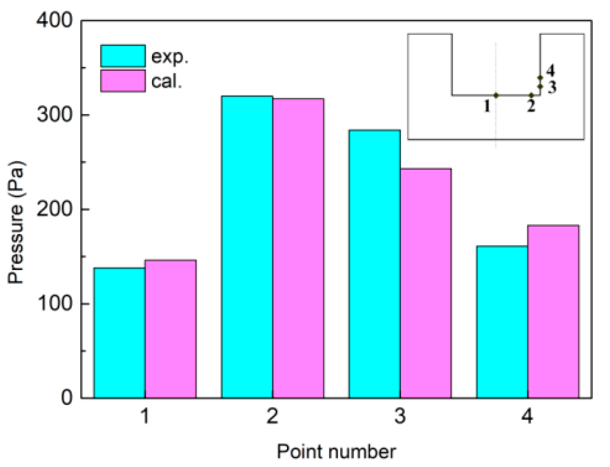
Arc pressure is one important factor influencing the formation of the weld bead; the predicted arc pressure at four different points on the narrow gap face is compared with the experimental data adapted from [16] with permission from Wang, J. 2018, as shown in Figure 15. Point 1 is at the bottom center; point 2 is 2 mm away from point 1; point 3 is 1 mm above the corner, and the distance between point 4 and point 3 is 1 mm. The maximum pressure appears at point 1; the calculated and experimental values are 317 and 320 Pa, respectively; their difference is small. The maximum difference of arc pressure appears at point 3; the calculated and experimental values are 243 and 284 Pa, respectively; the difference is 41 Pa, which is about 14% of the experimental value.
4. Conclusions
- (1)
- A unified 3D simulation model for LMF-NG-GTAW is developed including the electrode, welding arc, weld pool, and work piece; it can simulate the arc behavior and the weld pool formation process.
- (2)
- The profile of the deflecting welding arc has a big effect on the heat flux distribution. When the magnetic-field strength is 6 mT, the axis of the arc column moves from the bottom to the side wall; the decrease of the maximum heat flux at the bottom is about one-half, and the maximum heat flux at the side wall is increased by a factor of 10. The heat flux is dispersed along the narrow groove face, and this is helpful to form a uniform penetration weld.
- (3)
- The flow pattern in the weld pool is different with different magnetic-field strength. When the magnetic field is suitable, the flow pattern can transfer heat from the bottom to the side wall.
- (4)
- The model is validated by experimental data from references. Both the percentage deviations of the simulation weld penetration at the side wall and at the bottom from the experimental results are lower than 10%.
Author Contributions
Methodology, X.J.; resources, H.W.; writing—original draft, X.J.; funding acquisition, X.J. All authors have read and agreed to the published version of the manuscript.
Funding
This research was funded by “National Natural Science Foundation of China, grant number 51705133” and “the Open Research Fund Program of Hubei Provincial Key Laboratory of Chemical Equipment Intensification and Intrinsic Safety, grant number 2019KA02” and “Wuhan Institute of Technology Science Foundation, grant number K202009”.
Conflicts of Interest
The authors declare no conflict of interest.
References
- Zhang, G.; Shi, Y.; Zhu, M.; Fan, D. Arc characteristics and metal transfer behavior in narrow gap gas metal arc welding process. J. Mater. Process. Technol. 2017, 245, 15–23. [Google Scholar] [CrossRef]
- Wang, J.; Zhu, J.; Fu, P.; Su, R.; Han, W.; Yang, F. A Swing arc system for narrow gap GMA welding. ISIJ Int. 2012, 52, 110–114. [Google Scholar] [CrossRef] [Green Version]
- Wang, J.; Zhu, J.; Zhang, C.; Xu, G.; Li, W. Effect of arc swing parameters on narrow gap vertical GMA weld formation. ISIJ Int. 2016, 56, 844–850. [Google Scholar] [CrossRef] [Green Version]
- Xu, G.; Wang, J.; Li, P.; Zhu, J.; Cao, Q. Numerical analysis of heat transfer and fluid flow in swing arc narrow gap GMA welding. J. Mater. Process. Technol. 2018, 252, 260–269. [Google Scholar] [CrossRef]
- Huang, J.; Chen, H.; He, J.; Yu, S.; Pan, W.; Fan, D. Narrow gap applications of swing TIG-MIG hybrid weldings. J. Mater. Process. Technol. 2019, 271, 609–614. [Google Scholar] [CrossRef]
- Guo, N.; Wang, M.; Guo, W.; Yu, J.; Feng, J. Study on forming mechanism of appearance defects in rotating arc narrow gap horizontal GMAW. Int. J. Adv. Manuf. Technol. 2014, 75, 15–20. [Google Scholar] [CrossRef]
- Wei, B.; Jia, C.; Wu, W.; Fang, C.; Wu, C. Stirring effect of the rotating arc on the molten pool during non-axisymmetric tungsten NG-GTAW. J. Mater. Process. Technol. 2020, 285, 116769. [Google Scholar] [CrossRef]
- Cai, X.Y.; Lin, S.; Fan, C.L.; Yang, C.L.; Zhang, W.; Wang, Y.W. Molten pool behaviour and weld forming mechanism of tandem narrow gap vertical GMAW. Sci. Technol. Weld. Join. 2016, 21, 124–130. [Google Scholar] [CrossRef]
- Cai, X.; Dong, B.; Lin, S.; Murphy, A.B.; Fan, C.; Yang, C. Heat source characteristics of ternary-gas-shielded tandem narrow-gap GMAW. Materials 2019, 12, 1397. [Google Scholar] [CrossRef] [Green Version]
- Sharma, P.; Chattopadhyaya, S.; Singh, N.K. A review on magnetically supported gas metal arc welding process for magnesium alloys. Mater. Res. Express 2019, 6, 082002. [Google Scholar] [CrossRef]
- Belous, V.Y. Conditions for formation of defect-free welds in narrow-gap magnetically controlled arc welding of low titanium alloys. Paton Weld. J. 2011, 3, 16–18. [Google Scholar]
- Kang, Y.H.; Na, S.J. Characteristics of welding and arc signal in narrow groove gas metal arc welding using electromagnetic arc oscillation. Weld. J. 2003, 82, 93S–99S. [Google Scholar]
- Sun, Q.; Wang, J.; Cai, C.; Li, Q.; Feng, J. Optimization of magnetic arc oscillation system by using double magnetic pole to TIG narrow gap welding. Int. J. Adv. Manuf. Technol. 2015, 86, 761–767. [Google Scholar] [CrossRef]
- Sun, Q.; Hun, H.F.; Li, W.J.; Liang, Y.C.; Feng, J.C. Electrode tips geometry and penetrating in narrow gap welding. Sci. Technol. Weld. Join. 2013, 18, 198–203. [Google Scholar] [CrossRef]
- Wang, J.; Feng, J.; Zhao, H.; Sun, Q.; Wang, S. Characteristics of welding and arc pressure in TIG narrow gap welding using novel magnetic arc oscillation. Int. J. Adv. Manuf. Technol. 2016, 90, 413–420. [Google Scholar] [CrossRef]
- Wang, J.; Sun, Q.; Zhang, T.; Zhang, S.; Liu, Y.; Feng, J. Arc characteristics in alternating magnetic field assisted narrow gap pulsed GTAW. J. Mater. Process. Technol. 2018, 254, 254–264. [Google Scholar] [CrossRef]
- Nomura, K.; Ogino, Y.; Hirata, Y. Shape control of TIG arc plasma by cusp-type magnetic field with permanent magnet. Weld. Int. 2012, 26, 759–764. [Google Scholar] [CrossRef]
- Liu, Z.; Li, Y.; Su, Y. Simulation and analysis of heat transfer and fluid flow characteristics of arc plasma in longitudinal magnetic field-tungsten inert gas hybrid welding. Int. J. Adv. Manuf. Technol. 2018, 98, 2015–2030. [Google Scholar] [CrossRef]
- Wang, L.; Chen, J.; Wu, C.; Luan, S. Numerical analysis of arc and droplet behaviors in gas metal arc welding with external compound magnetic field. J. Mater. Process. Technol. 2020, 282, 116638. [Google Scholar] [CrossRef]
- Lowke, J.J.; Tanaka, M. ‘LTE-diffusion approximation’ for arc calculations. J. Phys. D Appl. Phys. 2006, 39, 3634–3643. [Google Scholar] [CrossRef]
- Murphy, A.B.; Arundelli, C.J. Transport coefficients of argon, nitrogen, oxygen, argon-nitrogen, and argon-oxygen plasmas. Plasma Chem. Plasma Process. 1994, 14, 451–490. [Google Scholar] [CrossRef]
- Cram, L.E. Statistical evaluation of radiative power losses from thermal plasmas due to spectral lines. J. Phys. D Appl. Phys. 1985, 18, 401–411. [Google Scholar] [CrossRef]
Figure 1.
Schematic diagram of longitudinal magnetic field-assisted narrow gap gas tungsten arc welding (LMF-NG-GTAW): (a) Front view; (b) Side view of the oscillation arc; (c) Waveform of the excitation current.
Figure 1.
Schematic diagram of longitudinal magnetic field-assisted narrow gap gas tungsten arc welding (LMF-NG-GTAW): (a) Front view; (b) Side view of the oscillation arc; (c) Waveform of the excitation current.

Figure 2.
Computational domain.
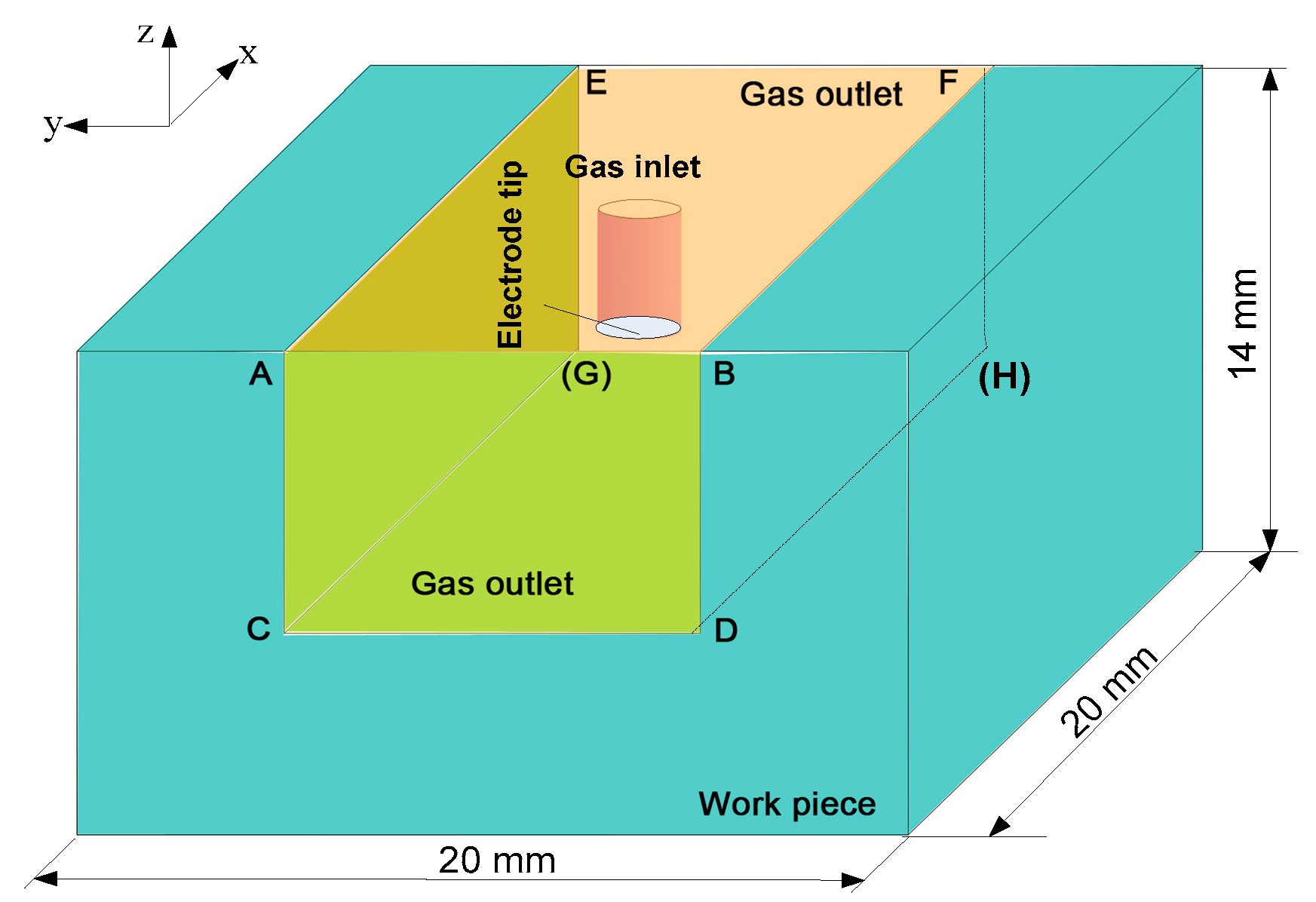
Figure 3.
Physical properties of pure argon: (a) Density; (b) Specific heat; (c) Viscosity; (d) Thermal conductivity; (e) Electric conductivity; (f) Radiation coefficient.
Figure 3.
Physical properties of pure argon: (a) Density; (b) Specific heat; (c) Viscosity; (d) Thermal conductivity; (e) Electric conductivity; (f) Radiation coefficient.
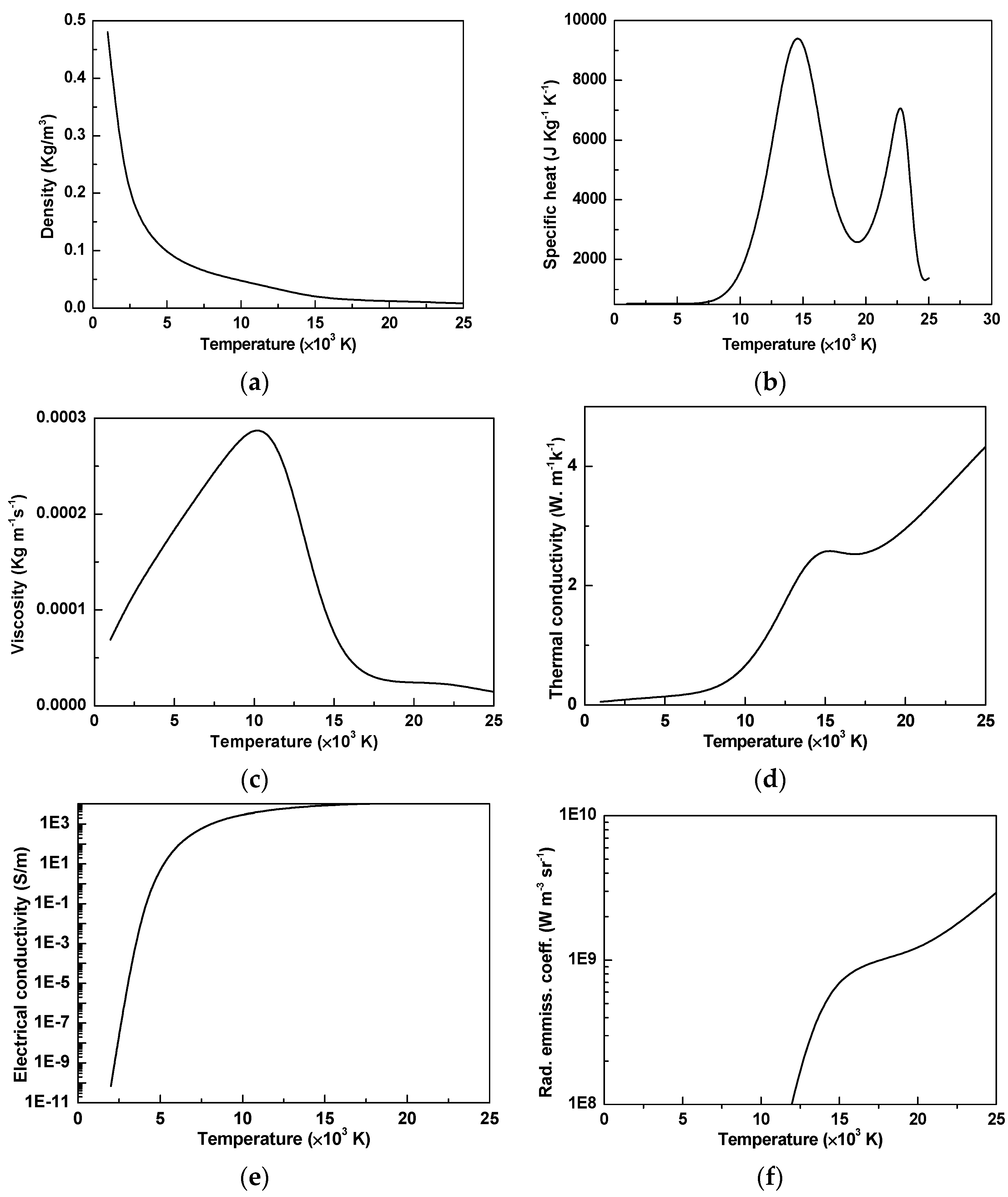
Figure 4.
Flow chart of the calculation.
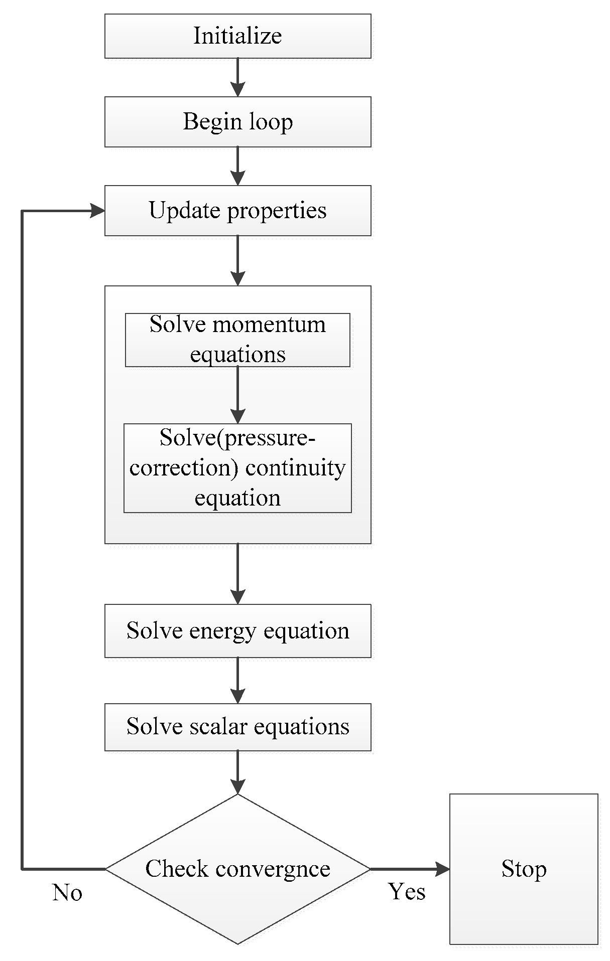
Figure 5.
The temperature field of the welding arc (B = 0 mT).
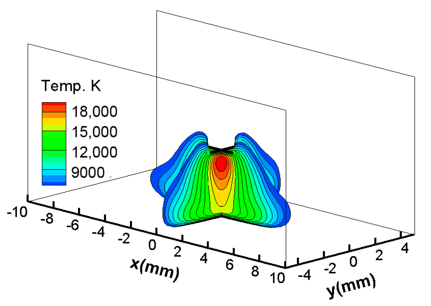
Figure 6.
The temperature field of the welding arc (B = 9 mT): (a) Temperature at cross-section y = 0, y = 1.5, y = 3, y = 4.5; (b) Temperature at cross-section x = 0.
Figure 6.
The temperature field of the welding arc (B = 9 mT): (a) Temperature at cross-section y = 0, y = 1.5, y = 3, y = 4.5; (b) Temperature at cross-section x = 0.
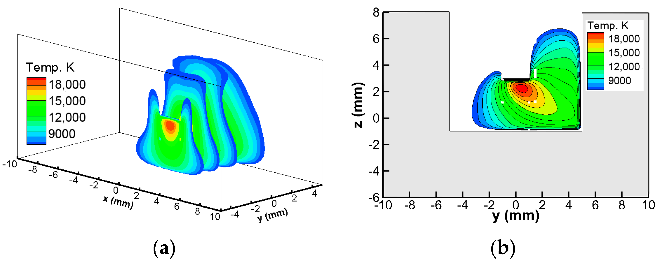
Figure 7.
Electromagnetic force in the arc column: (a) B = 0 mT; (b) B = 9 mT.

Figure 8.
Temperature of the welding arc at cross-section x = 0 at different magnetic fields: (a) B = 0 mT; (b) B = 3 mT; (c) B = 6 mT.
Figure 8.
Temperature of the welding arc at cross-section x = 0 at different magnetic fields: (a) B = 0 mT; (b) B = 3 mT; (c) B = 6 mT.
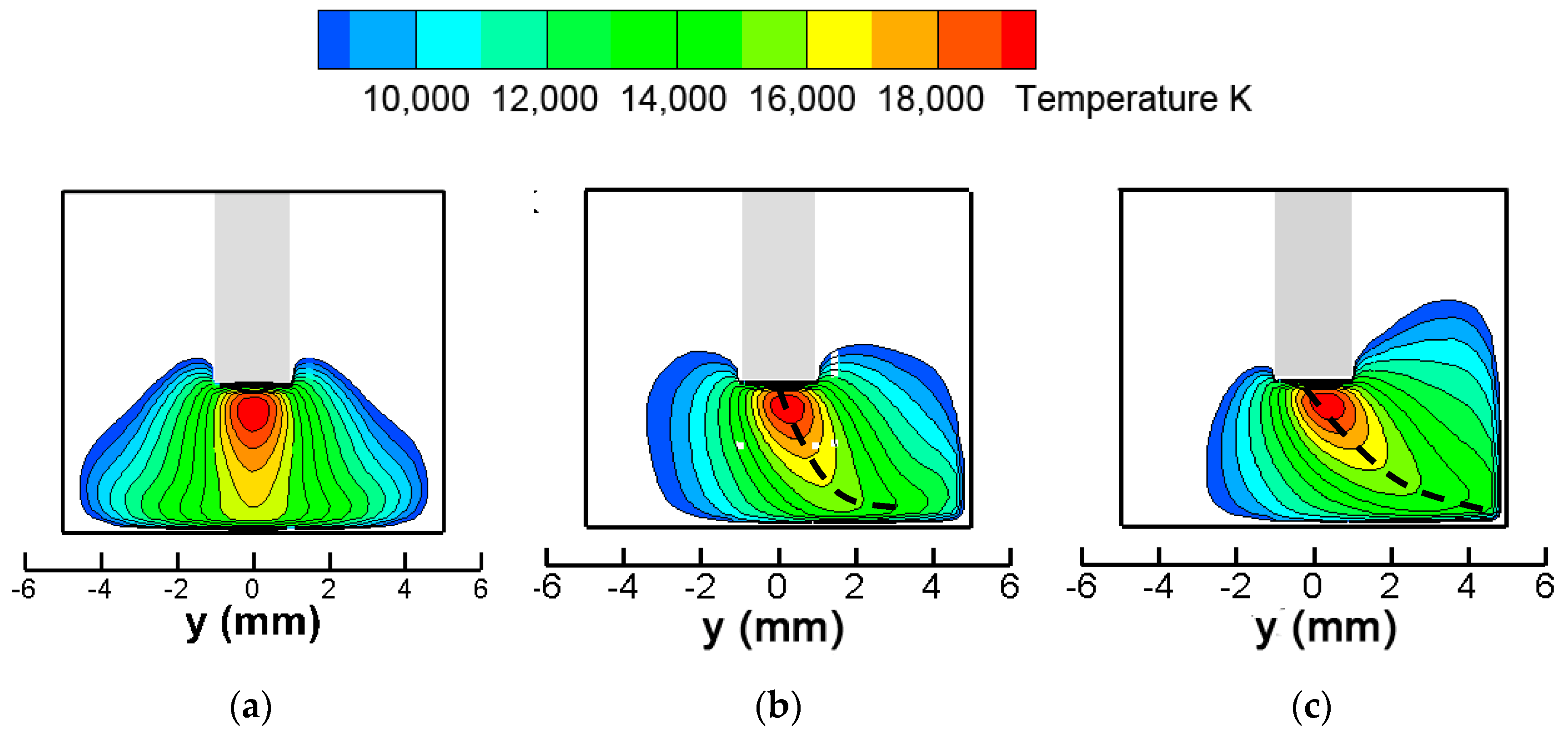
Figure 9.
Heat flux distribution at the bottom and side wall of x = 0 cross-section: (a) Heat flux at bottom; (b) Heat flux at side wall.
Figure 9.
Heat flux distribution at the bottom and side wall of x = 0 cross-section: (a) Heat flux at bottom; (b) Heat flux at side wall.
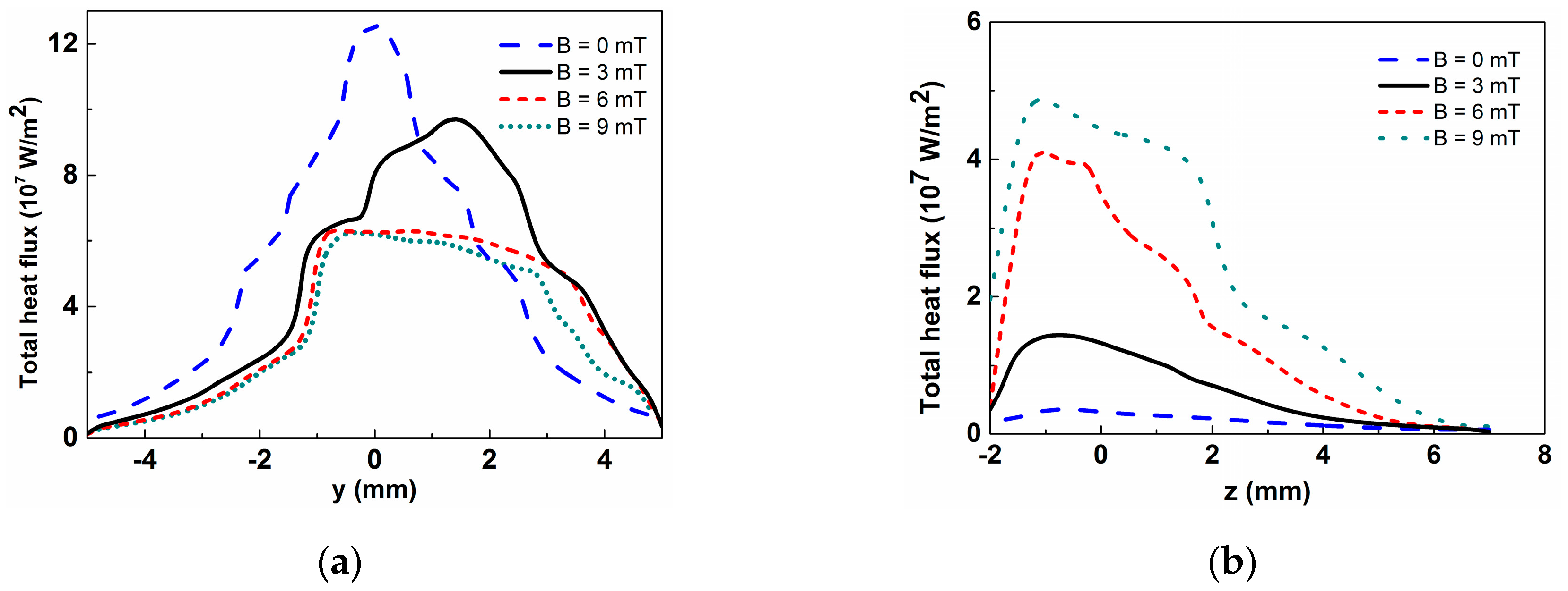
Figure 10.
The positions of the deflecting arc outlines at different time (B = 9 mT).
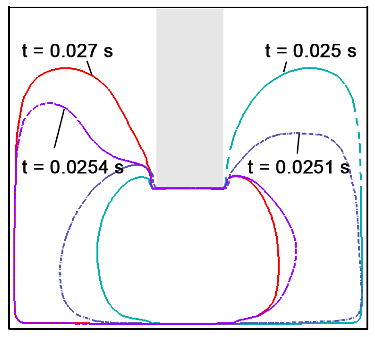
Figure 11.
The temperature field at cross-section x = 0 (t = 0.37 s): (a) B = 0 mT; (b) B = 3 mT; (c) B = 9 mT; (d) Weld pool dimension (unit: mm).
Figure 11.
The temperature field at cross-section x = 0 (t = 0.37 s): (a) B = 0 mT; (b) B = 3 mT; (c) B = 9 mT; (d) Weld pool dimension (unit: mm).
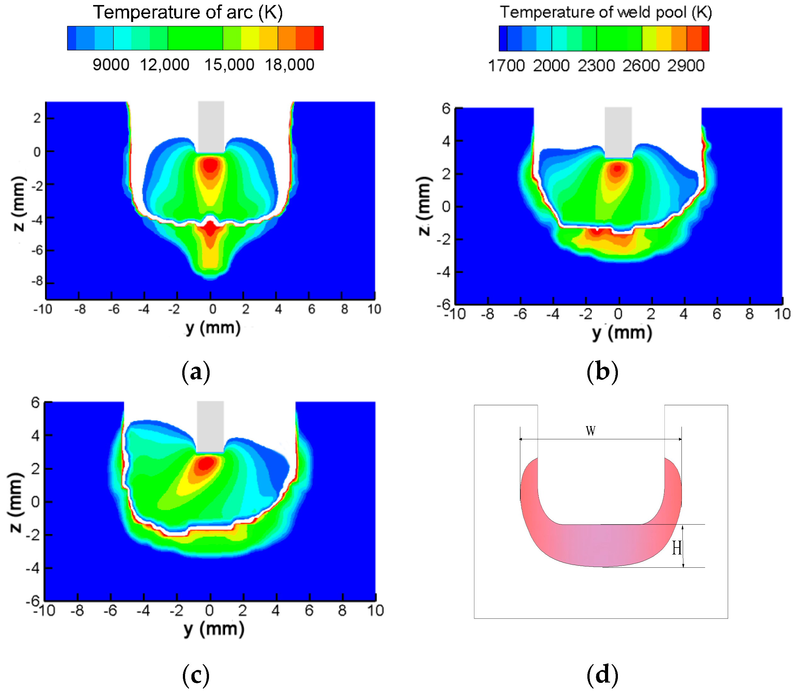
Figure 12.
Velocity distribution at cross-section x = 0 (t = 0.37 s): (a) B = 0 mT; (b) B = 3 mT; (c) B = 9 mT.
Figure 12.
Velocity distribution at cross-section x = 0 (t = 0.37 s): (a) B = 0 mT; (b) B = 3 mT; (c) B = 9 mT.
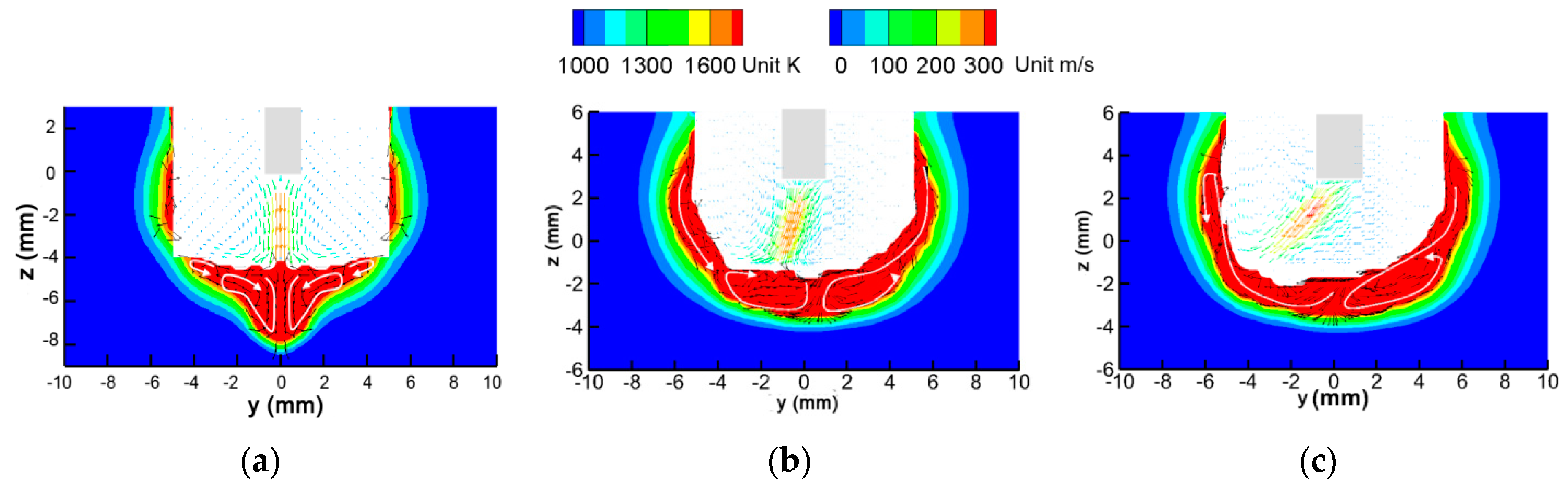
Figure 13.
Forces in the weld pool and their effects on the molten metal.

Figure 14.
The calculated weld shape.
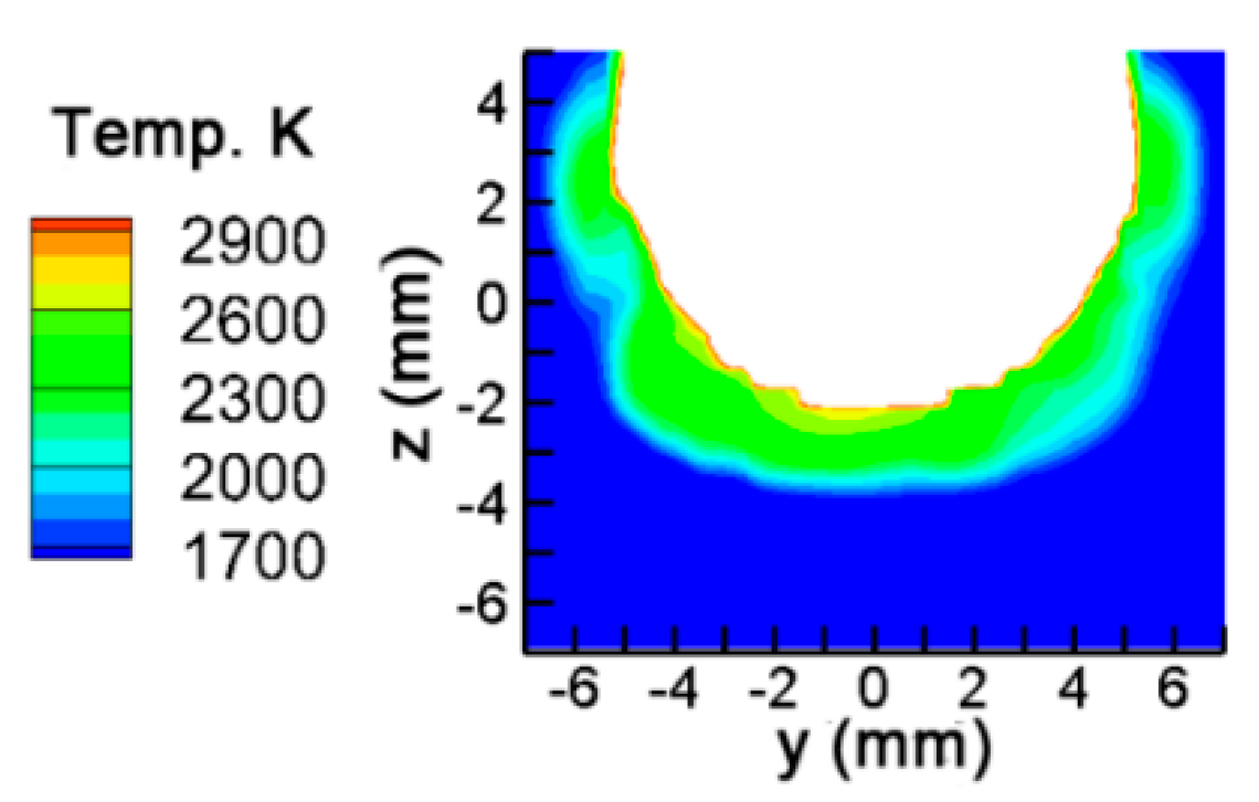
Figure 15.
Comparison between simulated and experimental arc pressure of four points, using experimental data from [16].
Figure 15.
Comparison between simulated and experimental arc pressure of four points, using experimental data from [16].

Table 1.
Boundary conditions.
| Boundary | T (K) | V (m/s) | Φ (V) | A |
|---|---|---|---|---|
| Gas inlet | 500 | vx = vy = 0, vz = vg | ||
| Electrode tip | 3000 | - | ||
| Electrode surface | 1000 | - | ||
| Gas outlet | 1000 | - | 0 | |
| External surfaces of work piece | - | ϕ = 0 |
Table 2.
Major physical properties of 304 stainless used in this model.
| Nomenclature | Value |
|---|---|
| freezing point | 1670 K |
| melting point | 1727 K |
| density | 7200 kg·m−3 |
| electric conductivity | 7.7 × 10⁵ S/m |
| surface tension coefficient | 1.2 N·m−1 |
| surface tension temperature gradient | 1 × 10⁻⁴ N·m−1·K−1 |
| work function | 4.65 eV |
Table 3.
Weld pool dimension at different magnetic field strength.
| Magnetic Field Strength (mT) | Weld Pool Width (mm) | Weld Pool Depth (mm) |
|---|---|---|
| B = 0 | 10.9 | 3.9 |
| B = 3 | 12.1 | 2.6 |
| B = 9 | 12.8 | 2.3 |
Table 4.
Comparison of measured and calculated welds.
| Experimental [13] | Simulation | Deviation | |
|---|---|---|---|
| Weld width (mm) | 14.6 | 14.2 | 2.8% |
| Weld depth (mm) | 2 | 1.8 | 8.7% |
© 2020 by the authors. Licensee MDPI, Basel, Switzerland. This article is an open access article distributed under the terms and conditions of the Creative Commons Attribution (CC BY) license (http://creativecommons.org/licenses/by/4.0/).
Share and Cite
MDPI and ACS Style
Jian, X.; Wu, H. Influence of the Longitudinal Magnetic Field on the Formation of the Bead in Narrow Gap Gas Tungsten Arc Welding. Metals 2020, 10, 1351. https://doi.org/10.3390/met10101351
AMA Style
Jian X, Wu H. Influence of the Longitudinal Magnetic Field on the Formation of the Bead in Narrow Gap Gas Tungsten Arc Welding. Metals. 2020; 10(10):1351. https://doi.org/10.3390/met10101351
Chicago/Turabian StyleJian, Xiaoxia, and Hebao Wu. 2020. "Influence of the Longitudinal Magnetic Field on the Formation of the Bead in Narrow Gap Gas Tungsten Arc Welding" Metals 10, no. 10: 1351. https://doi.org/10.3390/met10101351
Note that from the first issue of 2016, this journal uses article numbers instead of page numbers. See further details here.