Article

Mechanical Properties of Friction Stir Welded AA1050-H14 and AA5083-H111 Joint: Sampling Aspect

Cape Peninsula University of Technology, Faculty of Engineering and the Built Environment, Mechanical Engineering Department, P.O. Box 1906, Bellville 7535, South Africa
*
Author to whom correspondence should be addressed.
Metals 2020, 10(2), 214; https://doi.org/10.3390/met10020214
Submission received: 10 December 2019 / Revised: 23 January 2020 / Accepted: 25 January 2020 / Published: 3 February 2020
(This article belongs to the Special Issue Advanced Welding Technology in Metals)

Abstract

:
Welding of dissimilar aluminium alloys has been a challenge for a long period until the discovery of the solid-state welding technique called friction stir welding (FSW). The discovery of this technique encouraged different research interests revolving around the optimization of this technique. This involves the welding parameters optimization and this optimization is categorized into two classes, i.e., similar alloys and dissimilar alloys. This paper reports about the mechanical properties of the friction stir welded dissimilar AA1050-H14 and AA5083-H111 joint. The main focus is to compare the mechanical properties of specimens extracted from different locations of the welds, i.e., the beginning, middle, and the end of the weld. The specimen extracted at the beginning of the weld showed low tensile properties compared to specimens extracted from different locations of the weld. There was no certain trend noted through the bending results. All three specimens showed dimpled fracture, which is the characterization of the ductile fracture.

1. Introduction

Friction stir welding (FSW) is classified as one of the welding techniques that joins materials through heat generated during friction occurring between the tool shoulder and the workpieces [1]. The invention of this welding technique was based on the materials which were classified as un-weldable materials through conventional methods. Those classified materials included certain classes of aluminium alloys. Aluminium alloys are mostly used in many industries like aviation, shipbuilding, and automotive because of their light weight. The focus towards FSW has expanded such that it includes testing the capability of the technique in welding other materials that are outside the aluminium class. This includes the welding of copper and its alloys, titanium and magnesium and its alloys [2]. When the aluminium alloys are welded with the conventional technique, they are likely to have weld splitting on the joint line. The fusion welding of aluminium alloys is more difficult than the welding of steel due to their low melting point, softness, and so forth. The aluminium alloys sometimes bend and shrink when welded using conventional welding and those effects are caused by residual thermal stress [3].
In some materials, FSW possesses good metallurgical properties when compared to fusion welding, and this is caused by the microstructural modification that occurs during welding. Mishra and Ma [4] reported that to have a great weld and to avoid defects on the weld, it is important to take welding parameters, material flow, and heat generation into consideration during the welding process.
There are mainly four crucial steps that are involved during the performance of FSW, i.e., plunging, dwelling, welding, and pulling. The rotating tool is inserted into the butt joint slowly until the shoulder touches the surface of the workpieces (plunging). The plunged tool remains in one location for a certain period with the purpose of building up input heat (dwelling). The plunged tool moves along the plates being joined at a specified speed (welding). The rotating tool gets removed vertically from the welded plates soon after reaching the ends of the plates (pulling), and this normally leaves a hole that indicates the end of the weld [5].
There are several studies focusing on FSW of aluminium alloys [6]. Typical examples include the production of Al/NiTi composites by FSW assisted by electrical current, analysis of welding properties in FSW of AA6351 plates added with silicon carbide particles, and dynamics of rotational flow in FSW of aluminium alloys [7,8,9]. It has been reported that for the production of the good weld, the tool geometry and welding parameters play a very important role. This includes the rotation speed, traverse speed, tool tilt angle, and plunged depth. Plunge depth has been found to be a critical parameter in the heat generation and for proper consolidation of material without defects. The plunge depth was also identified as one of the parameters that plays an important role towards the microstructural arrangement of the joint [10].
Welding dissimilar materials is quite challenging when compared with similar welding materials due to the difference in mechanical properties and chemical composition of the base materials. To acquire better weld mechanical properties, the harder material must be placed on the retreating and softer material placed in the advancing side [11,12]. The tool geometry plays a very important role in welding dissimilar materials. Welding dissimilar alloys requires the use of different tool profiles such as threaded, squared, and triangular profiles to transfer the material from top of the joint to bottom and vice versa by stirring movement [13]. Kundu and Singh [14] reported that tool pin profile geometry plays an important role in weld quality, while the surface quality of the weld joint depends upon the tool tilt angle. The increase in tool tilt angle affects the flow and fill up of material during welding.
In most cases, the welding of dissimilar materials involves the welding of aluminium alloys, which are not far from each other in terms of mechanical properties, e.g., 5xxx will be welded together with 6xxx, 6xxx welded with 7xxx, etc. Recently, there are attempts that have been made in trying to weld the aluminium alloys that are mechanically far apart from each other, i.e., FSW of AA2024 to AA6061 [15]. This investigation used a single- and a dual-pin tool. The defect-free joint was obtained in all selected parameters except the welding speed beyond 90 mm/min. The onion rings were visible on the nugget region for joints produced using the dual-pin tool but absent on the single-pin tool. The highest ultimate tensile strength (UTS) was obtained with the dual-pin tool at a welding speed of 150 mm/min, whereas the single-pin produced the UTS at a welding speed of 90 mm/min. However, the UTS provided by single-pin was always less than the one produced by the dual-pin tool.
There are various aspects that have been studied through the use of dissimilar materials. This involves the analysis of the strain hardening behaviour on the friction stir welded dissimilar alloys, which are mechanically far apart from each other, i.e., 2024-T351 and 5083-H112, 2024-T351 and 7075-T651 [16]. This analysis was performed on two types of joints, i.e., 2024-T351 and 5083-H112, with 2024-T351 on the advancing side and 5083-H112 on the retreating side. The second joint was 2024-T351 and 7075-T651, with 2024-T351 on the retreating side and 7075-T651 on the advancing side. It was discovered that the strain-hardening rate of the AA7075/AA2024 joint was higher than that of the parent material, while the strain-hardening rate of the AA2024/AA5083 joint lay between those of the parent material. It was also found that the tensile properties of both joints were lower than those of the parent material. Xia-Wei et al. [17] did the microstructural analysis correlatively with mechanical properties of the FSW joint using dissimilar alloys. The lamellar structure in the bottom of the nugget zone was found to be more homogeneous and finer than other regions. The hardness on the copper side of the nugget was higher than that on the aluminium side. The UTS of the joint was found to be relatively lower than that of the base metal. The tensile morphology revealed ductile-brittle fracture mode.
Kumbhar and Bhanumurthy [18] did a comparative study on friction stir welding of similar to dissimilar aluminium alloys, i.e., AA5052 to AA6061, and AA6061 to AA6061. The similar and dissimilar joints were produced at various combinations of tool rotation speeds and tool traverse speeds. The microstructural analysis revealed that there was no rigorous mixing in the nugget region for both materials. The tensile properties of dissimilar materials (AA5052-AA6061) were much better compared to the properties of similar materials (AA6061-AA6061). Welding dissimilar aluminium alloys that are mechanically far apart has gained much attention and interest from researchers [19]. This includes the analysis of friction stir welding of dissimilar AA2017A-T451 and AA7075-T651 plates at a different tool rotation speed. The results revealed that the best tensile properties were achieved when AA2017A-T451 was on the retreating side. It was also established that the material that is located on the retreating side dominates the weld centre, and this is consistent with the results reported by other researchers [11,12,16]. Ranjith and Kumar [20] analysed the impact of joining two dissimilar aluminium alloys AA2014 T651 and AA6063 T651 by friction stir welding. They discovered that the tensile strength was better when the tool was offset towards AA2014 (advancing side). When it was offset towards AA6063 (retreating side), it resulted in insufficient heat generation on the advancing side, which then resulted in an incomplete fusion of AA2014. Sarsılmaz and Caydas [21] conducted a study on statistical analysis on mechanical properties of friction-stir-welded AA1050-H14/AA5083-H321 couples. The study investigated the effect of friction stir welding parameters focusing on rotational speed, traverse speed, and stirrer geometry. In their investigation, they discovered that traverse speed has a significant effect on UTS and nugget hardness. Their analysis also included the optimized welding parameters to be used in welding the said aluminium alloys.
The analysis of the effect of material positioning during FSW has gone outside the aluminium family. This includes the study which analyzed the effect of location variation in FSW of steel with different carbon content. It was discovered that the placement of the stronger material on the advancing side reduced the weld nugget size and increased the amount of martensite formation. The location of the strongest material on the advancing side led to higher temperature and stress due to the highest temperature on the advancing side [22]. It is evident from the literature that the FSW that involved materials that are mechanically apart involved mainly 2xxx as the weaker material. There are very few studies which utilized AA1xxx [21].
This paper reports on the mechanical properties of the weld produced by the friction stir welding technique using AA1050-H14 and AA5083-H111. The AA1050-H14 is mostly used in the chemical industry, automotive industry, reflectors, heat exchangers, and food industry [23]. The AA5083-H111 is widely used in the prevention of corrosion, hence used in shipbuilding. This alloy is also used in the automotive industry as well [24]. It was then crucial to analyze different aspects related to the joint formed from these two distinct materials. This was done so as to prepare the future application of these two materials in producing products and components. It then became crucial to analyze comparatively the mechanical behaviour of the joint in different locations. This type of analysis will give information regarding the best location for sampling the welds produced from the materials with unique properties and composition.

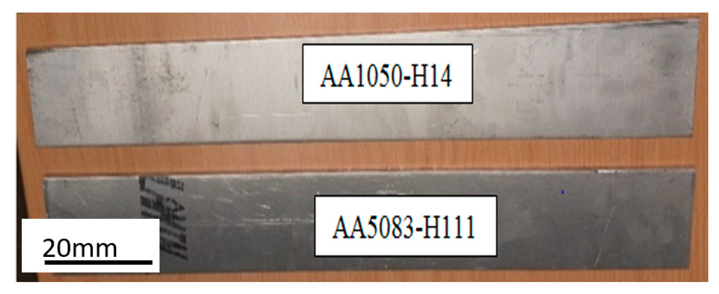
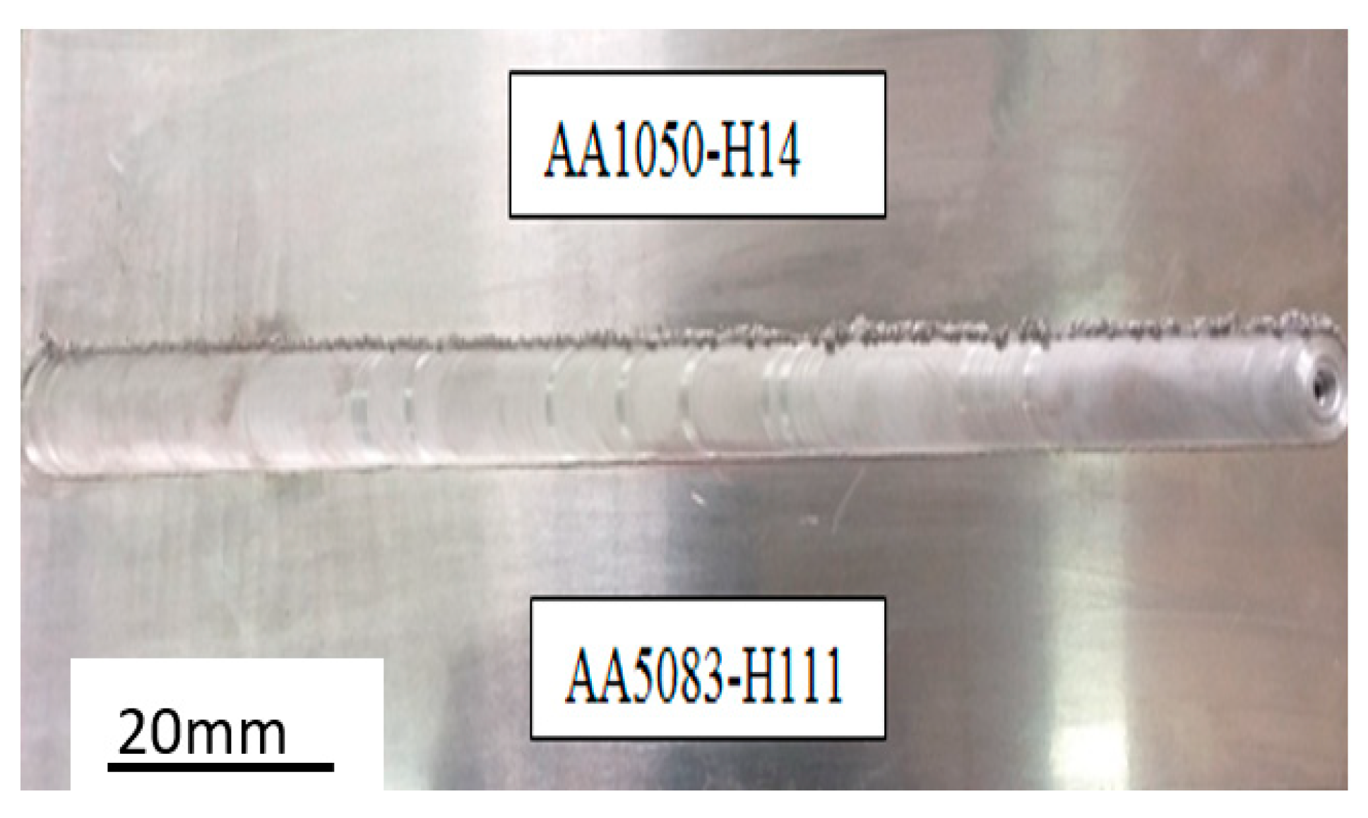
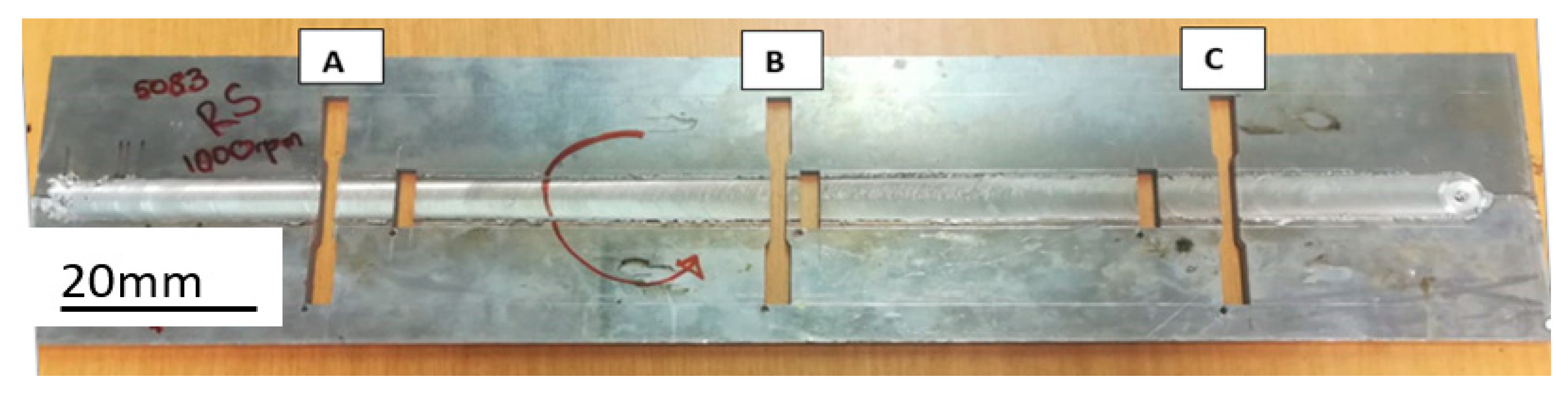
2. Experimental Procedure

The 6mm thick AA1050-H14 and AA5083-H111 plates were cut into 70 mm × 530 mm long strips using a guillotine cutting machine (see Figure 1).
The two dissimilar plates were fixed on the backplate of the semi-automated milling machine (FSW machine), as shown in Figure 2. The AA5083-H111 was kept on the retreating side throughout the experiments, while AA1050-H14 was on the advancing side. This kind of material location was followed based on the recommendation from the literature [11,12,16,19,25,26]. The plates were fixed on the machine’s backplate by eight clamps. The function of clamps was to make sure the plates did not move apart when the rotating pin was in motion.
The plates were then friction stir welded using a high carbon steel (H13) tool shown in Figure 3. The tool was machined using a lathe machine and was heat-treated to about 50HRC. The profile of the pin was triangularly threaded with a 20 mm shoulder diameter and 6 mm pin diameter. The triangular threaded pin had a 1mm pitch and the height of 5.8 mm. The FSW parameters used in this study are presented in Table 1, and these parameters were chosen based on various speed test combinations performed prior to the main welding. However, those trial results are not included in this work since they are not part of the paper’s focus.
Figure 4 shows the friction stir welding of 6 mm thick AA1050 and AA5083 plates. Stage 1 shows two plates ready for welding. Stage 2 shows the rotating tool plunged into the two pieces being welded, i.e., AA1050-H14 and AA5083-H111. Stage 3 shows the welded part of the plates. Stage 4 shows the end of FSW and the unplunging of the tool. The finished product is clearly shown in Figure 5. The nominal chemical composition for materials used in this study is presented in Table 2. The chemical composition was measured using the BELEC COMPACT PORT HLC spectrometer (Belec Spektrometrie Opto-Elektronik GmbH, Georgsmarrienhutte, Germany) according to ASTM E716-16 standard. These chemical compositions were in the range of those reported in the literature [16,21,27].

3. Welded Joint Analysis
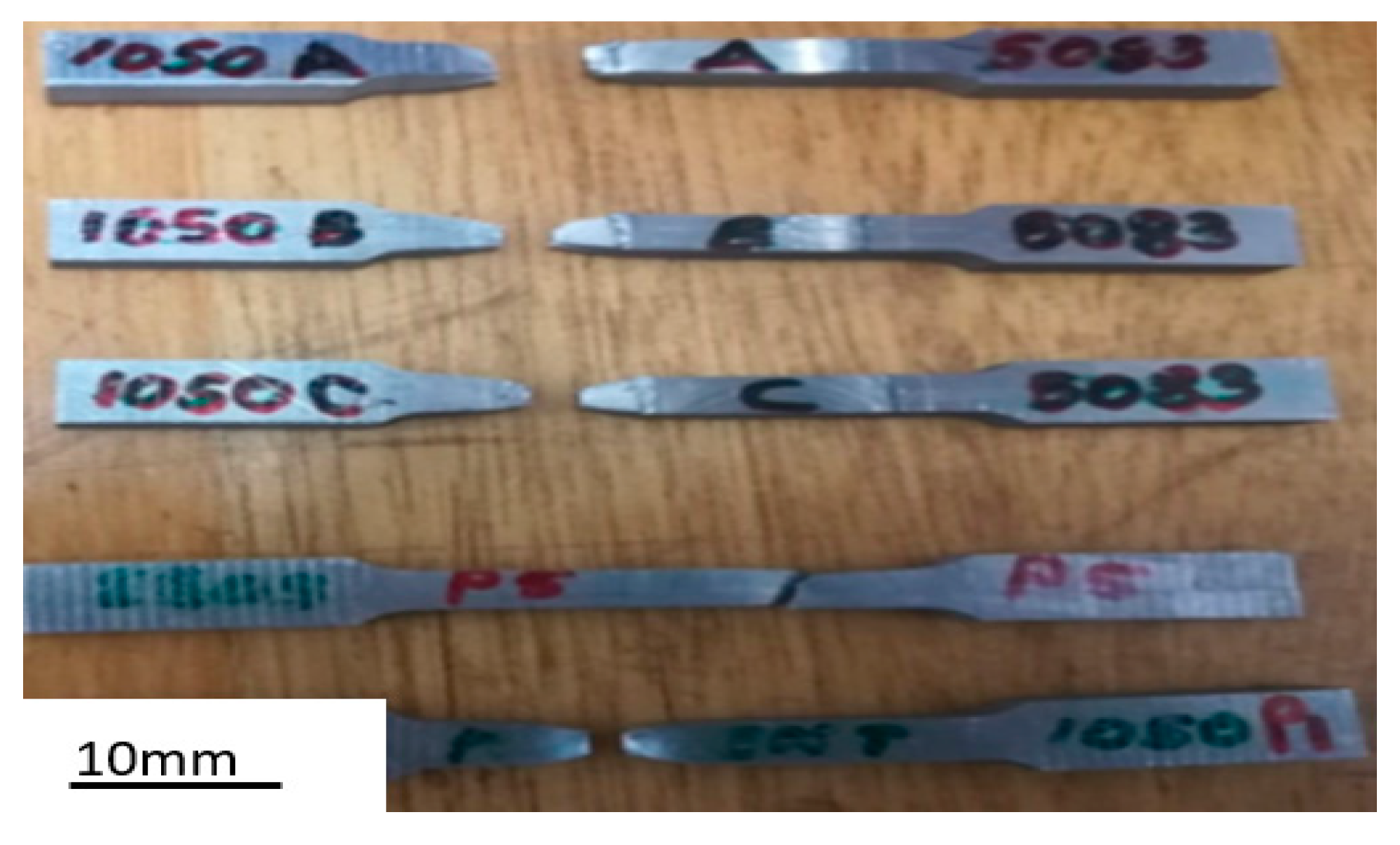
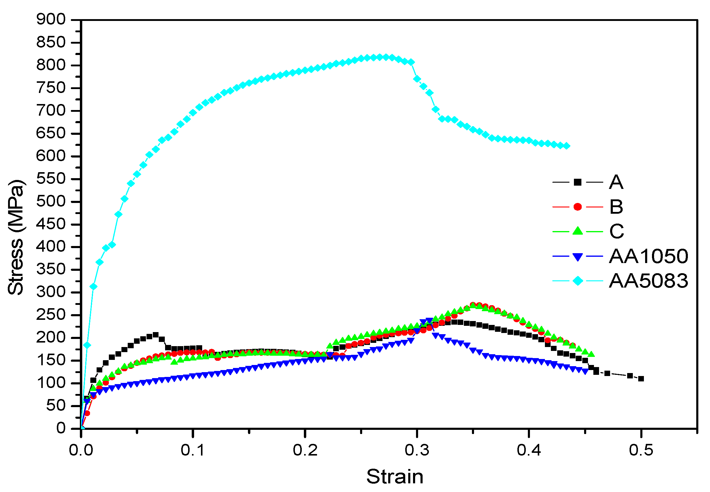
This section describes the mechanical and microstructural analysis of the welded joint. This includes the use of the tensile test machine, microstructure analysis, bending test, and scanning electron microscope (SEM). It should be noted that the friction stir welded joint had start, middle, and end points. The specimens were all labeled A, B, and C. Label A indicated the specimens cut at the beginning of the joint, specimens cut in the middle were labeled B, while C symbolized the specimens cut at the end of the joint. This format was followed throughout the performance of the tests.

3.1. Tensile Test

The machine that was used for the tensile test was the Hounsfield tensometer (universal testing machine). The tensile test was performed using the ASTM E8 standard. The tensile test specimens were cut perpendicular to the welding direction (see Figure 6). The tensile test specimens were designed according to the ASTM E8M-04 standard [28] for accurate dimensions. The specimens were cut using CNC wire cutters and the coordinates for cutting specimens were manually generated using 2-D drawings in Solidworks, shown in Figure 7. This method of cutting was selected because it does not induce heat during cutting. There were three tensile specimens extracted from different locations of the plate (see Figure 6). The extensometer was used to capture the data relevant to the joint.
The specimens were tensile tested until they fractured.

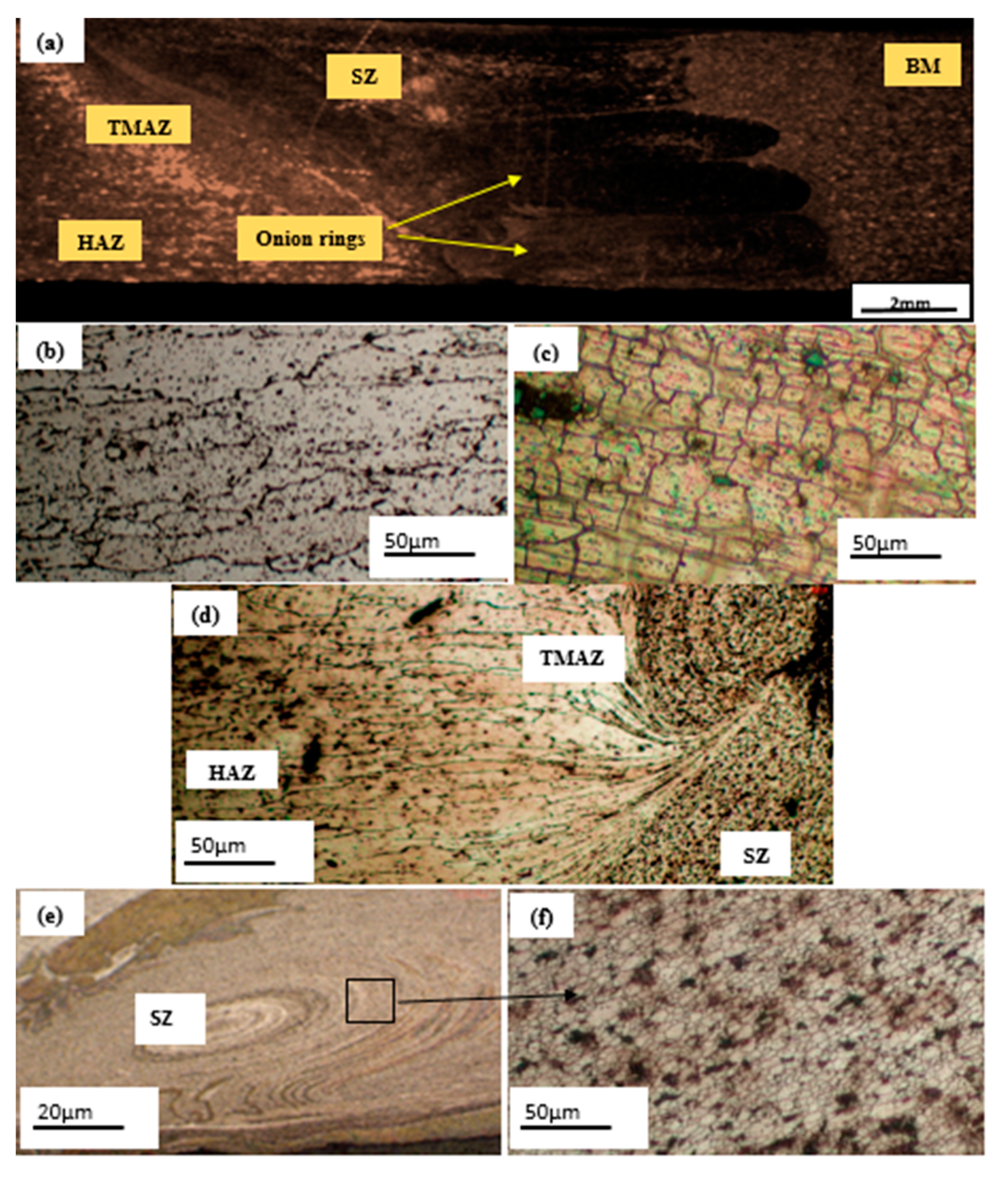
3.2. Microstructure Analysis
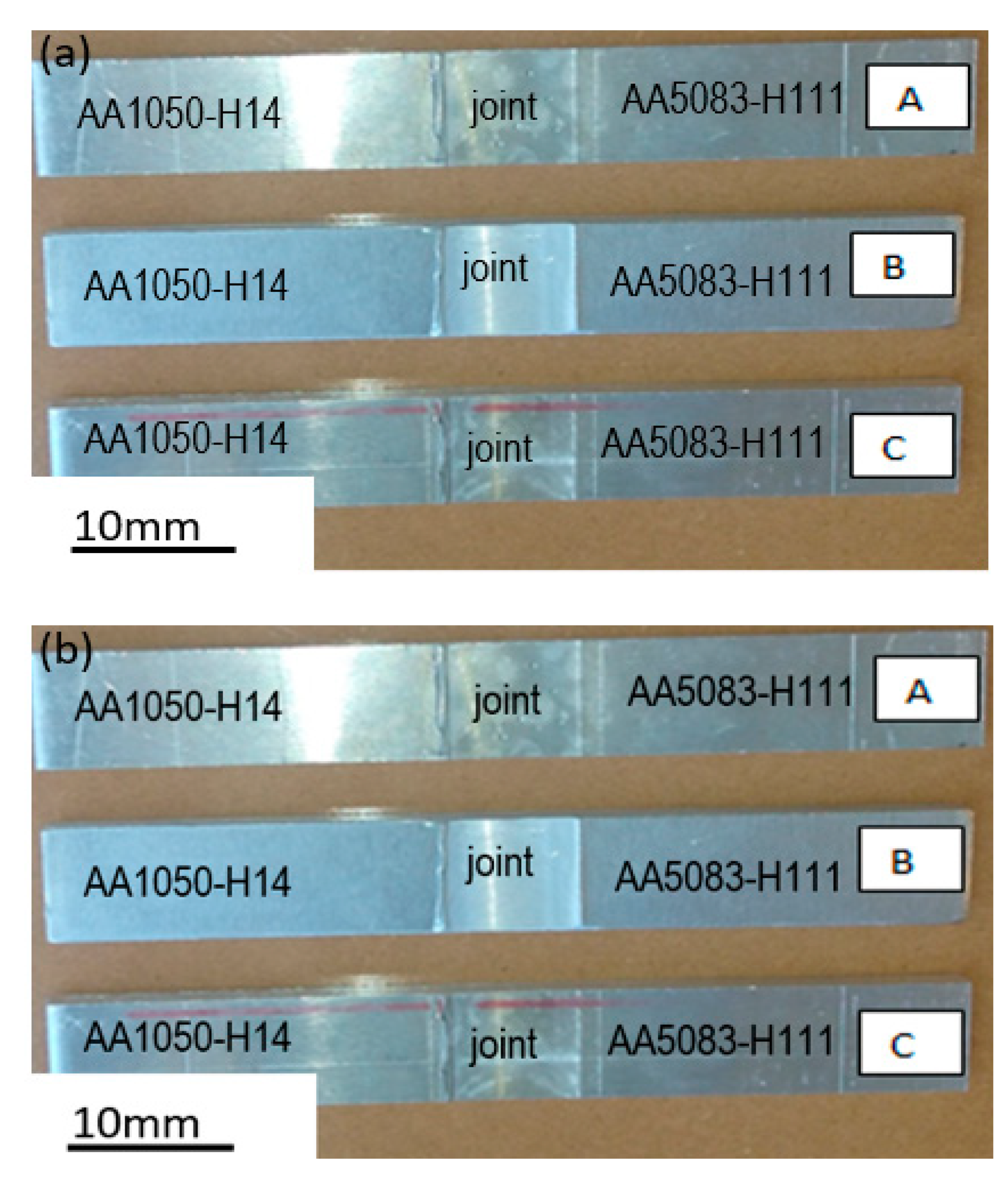
The microstructure analysis was performed using the Nikon Eclipse L150 microscope (Nikon, Tokyo, Japan). The microstructure was observed under a polarized slider with an Axiocam 105 colour camera for acquiring the pictures. The specimens were cut into 26 × 8 × 6 mm using the CNC wire cutter and prepared for analysis using Keller’s reagent etchant.

3.3. Bending Test

Three-point bending tests were conducted using the same Hounsfield tensometer previously used for the tensile tests. The performance of the bending test was based on the ASTM E290-97a standard. There were six rectangular-shaped specimens prepared for bending tests. The bending tests were performed on the face and the root of the joint. The three specimens presented in Figure 8 show the face of the joint (the surface that was in contact with the tool shoulder) and another three presented in Figure 9 show the root of the joint (the surface that was in contact with the backplate). For comparative purposes, the bending test was also performed on parent materials.

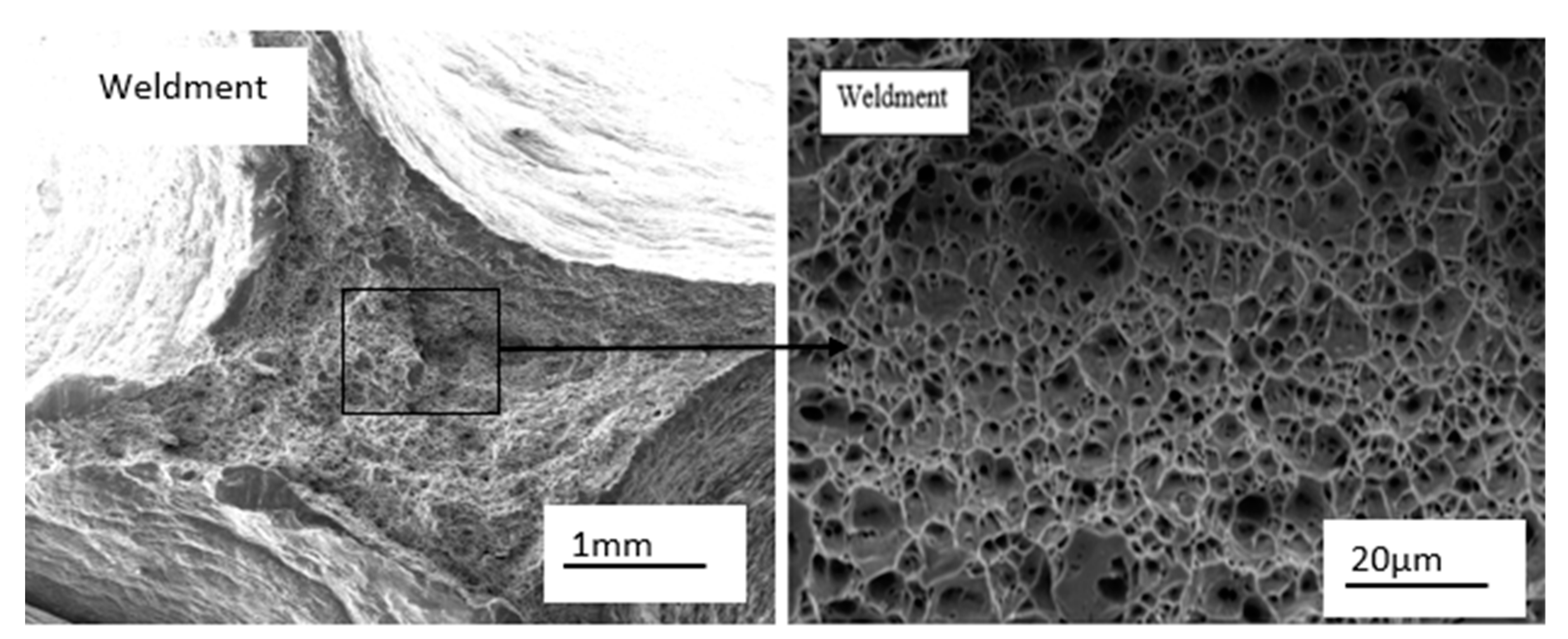
3.4. Scanning Electron Microscope (SEM)

The SEM used was the Zeiss Auriga (Carl Zeiss Microscopy GmbH Co., Germany). Prior to the analysis, the samples were coated with a layer of carbon to ensure sufficient conductivity during analysis. The results obtained are presented and explained in the next section.

4. Results and Discussion

The detailed discussions of the results obtained from the various tests performed are presented in this section. The results obtained include the tensile test, bending test, microstructure and SEM analysis.

4.1. Microstructure

The FSW joint was characterized by general unique zones as shown in Figure 9. Those zones included the stir zone (SZ) around the weld centre line, the thermo-mechanically affected zone (TMAZ) on both sides of the weld nugget/stir zone, the heat-affected zone (HAZ), which surrounded the TMAZ, and the non-affected base metal (BM) [12,13,14,15,16,17,18]. The regions originated from the material flow behaviour caused by the tool rotation. The macroscopic and microscopic patterns of the three specimens were similar, hence one pattern is presented to avoid duplication. Figure 9a shows the macroscopic view of the joint with its thermal zones. There are no defects visible on the joint. This suggests that the welding was performed successfully [21,29]. Figure 9b,c shows the micrographs of base metals AA1050-H14 and AA5083-H111, respectively. Figure 9d shows the microscopic view of the AA1050-H14 pulled towards the stir zone, and this morphology is called hook defect [30]. Figure 9e shows rotational traces of the materials at the stir zone. Figure 9f shows the magnified morphology of the stir zone. The magnified view shows the refined grain structures at the stir zone. The average grain size for the base metal AA1050-H14 was about 29 µm while the average grain size of AA5083-H111 base metal was about 7.3 µm. The average grain size for the stir zone was about 9.35 µm. The average grain size for the stir zone is close to the average grain size for AA5083-H111 base metal.

4.2. Tensile Test

Figure 10 shows the fractured specimens post tensile tests. It was observed that the fracture occurred on the advancing side (AA1050) of the specimen. This behaviour suggests that the weld joint was mechanically stronger than the AA1050 alloy [11,12,28]. This also suggests that the welded joint was dominated by AA5083-H111, hence it was stronger [16,29,30,31].
Table 3 shows the results of the ultimate tensile stress (UTS) and percentage elongation. The AA1050 and AA5083 show the UTS of 104.89 MPa and 326.75 MPa, respectively, while the FSW specimens A, B, and C show 50.67 MPa, 66.47 MPa, and 63.19 MPa, respectively. It should be noted that all the specimens were fractured by the HAZ region of the AA1050-H14 side. The HAZ region is known to have a negative impact towards the UTS of a material due to the coarsened grains that are normally associated with this region [19,20,30,31,32,33]. This is suggested to be the cause of the lower UTS for the three specimens compared to the parent materials. This assumption is in line with the grain variations observed during microstructural analysis. The percentage elongation was found to be 19%, 25%, and 26% for specimen A, B, and C, respectively. These indicate that the FSW specimens B and C were more ductile compared to the specimen A and AA1050-H14 parent material, but less ductile compared to parent material AA5083.
Figure 11 shows the tensile test-strain curve of AA1050-H14, AA5083, and FSW specimens A, B, and C. The UTS of the parent material AA5083 was larger than that of the parent material AA1050-H14 and of the FSW specimens. Specimen A, which was the first specimen from the welded plate, was the weakest while specimens B and C were close to each other. This behaviour was assumed to be caused by insufficient heat input at the beginning of the weld. The temperature stabilized from the middle to the end of the plate, hence improved UTS.

4.3. Bending Test

Figure 12 and Figure 13 are the post-bending test specimens for FSW and parent materials. The reddish-brown line appearing on specimens in Figure 12a,b indicates the center of the joint. The face and the root bending occurred towards the advancing side of the joint. This behaviour suggests that the joint was mechanically stronger compared to AA1050-H14, hence bending occurred on the advancing side. This behaviour is in agreement with the behaviour observed in the tensile analysis. The post-bending results showed the tested specimens without failure. This means that the welded materials bonded well during welding.
Figure 14 and Figure 15 show bending stress and strain curves of the joint, together with parent materials. As it has been mentioned before that all the welded specimens bent on AA1050-H14, the flexural stresses for both face and root were within the range of that of AA1050-H14 (see Table 4). The average stress for face and root was 218.94 MPa and 259 MPa, respectively. These values suggest that the root side of the weld was stronger than that of the face. This could be caused by the fact that the lower side of the weld was exposed to the restricted downward movement due to bed backing plate. The flexural stress values were comparatively higher than the tensile values and this was due to higher temperatures involved during FSW.

4.4. Scanning Electron Microscopy (SEM)

It should be noted that the fractured surface for base metals was studied comparatively with specimen C. The elimination of other specimens was due to the fact that there was no distinction on the surface morphology for the other specimens. Figure 16 and Figure 17 show the surface morphologies of the base metals and weldment (joint). All the specimens showed a cup-like dimpled fracture, which is a characterization of ductile failure mode [30,32,33]. The similarity in surface fracture suggests that the ductility of the materials involved in the joint formation was preserved post welding even though there was some percentage of elongation variation.

5. Conclusions

The absence of voids or defects on the macrostructure of the joint suggests the success of welding the two dissimilar aluminium alloys (AA1050-H14 and AA5083-H111). The UTS of the base metals was found to be higher than the UTS of the tested specimens. In addition to this, the specimen extracted at the beginning of the weld exhibited the lowest UTS compared to the specimens extracted from other locations of the weld. The ductility of the specimens fluctuated between that of the parent materials. The fracture location was found to be consistent with the one reported in the literature [11,12,16]. This kind of failure is due to the coarsened grain found in the location of failure (AA1050-H14 HAZ region). The characteristic hook defect on the side of the weaker material was also observed during the microstructural analysis [29,30,31,33]. The morphology of the fracture surface indicated ductile failure mode, which was characterized by cup-like dimples for all the specimens.

Author Contributions

Authors have contributed equally to this work. All authors have read and agreed to the published version of the manuscript.

Funding

This research received no external funding.

Acknowledgments

Authors would like to thank EM Masekwana for his technical assistance during welding.

Conflicts of Interest

The authors declare no conflict of interest.

References

  1. Mishra, R.S.; Mahoney, W. Friction stir welding and processing. ASM Int. 2007, 1, 368. [Google Scholar]
  2. Thomas, W.; Nicholas, E. Friction stir welding for the transportation industries. Mat. Des. 1997, 18, 269–273. [Google Scholar] [CrossRef]
  3. Genevois, C.; Deschamps, A.; Denquin, A.; Boisneau-Cottignies, B. Quantitative investigation of precipitation and mechanical behaviour for AA2024 friction stir welds. Act. Mat. 2005, 53, 2447–2458. [Google Scholar] [CrossRef]
  4. Mishra, R.S.; Ma, Z.Y. Friction stir welding and processing. Mat. Sc. Eng. 2005, 50, 1–78. [Google Scholar] [CrossRef]
  5. Farias, A.; Batalha, G.F.; Prados, E.F.; Magnabosco, R. Tool wear evaluations in friction stir processing of commercial titanium Ti-6Al-4V. Int. J. Sc.Techn. Fric. Lub. Wr. 2013, 302, 1327–1333. [Google Scholar] [CrossRef]
  6. Tiwari, S.K.; Shukla, D.K.; Chandra, R. Friction Stir Welding of Aluminium Alloys: A review. Int. J. Mech. Aer. Ind. Mechat. Manuf. Eng. 2013, 7, 1326–1331. [Google Scholar]
  7. Liu, X.C.; Sun, Y.F.; Morisada, Y.; Fujii, H. Dynamics of rotational flow in friction stir welding of aluminium alloys. J. Mat. Proc. Tech. 2018, 252, 643–651. [Google Scholar] [CrossRef]
  8. Oliveira, J.P.; Duarte, J.F.; Inácio, P.; Schell, N.; Miranda, R.M.; Santos, T.G. Production of Al/NiTi composites by friction stir welding assisted by electrical current. Mat. Des. 2017, 113, 311–318. [Google Scholar] [CrossRef] [Green Version]
  9. Nallusamy, S. Analysis of Welding Properties in FSW Aluminium 6351 Alloy Plates Added with Silicon Carbide Particles. Int. J. Eng. Res. Afr. 2016, 21, 110–117. [Google Scholar] [CrossRef]
  10. Soundarajan, V.; Yarrapareddy, E. Investigation of the friction stir lap welding of aluminium alloys AA 5182 and AA 6022. J. Mat. Eng. Perf. 2007, 16, 477–484. [Google Scholar] [CrossRef]
  11. Sadeesh, P.; Rajkumar, P.; Avinash, N.; Arivazhagan, K.; Narayanan, S. Studies on friction stir welding of AA 2024 and AA 6061 dissimilar metals. Proc. Eng. 2014, 75, 145–149. [Google Scholar] [CrossRef] [Green Version]
  12. Amancio-Filho, S.T.; Sheikhi, S.; dos Santos, J.F.; Bolfarini, C. Preliminary study on the microstructure and mechanical properties of dissimilar friction stir welds in aircraft aluminium alloys 2024-T351 and 6056-T4. J. Mat. Proc. Techn. 2008, 206, 132–142. [Google Scholar] [CrossRef] [Green Version]
  13. Biswas, P.; Kumar, D.A. Friction stir welding of aluminium alloy with varying tool geometry and process parameters. J. Eng. Man. 2011, 226, 641. [Google Scholar] [CrossRef]
  14. Kundu, J.; Singh, H. Friction stir welding of dissimilar Al alloys: Effect of process parameters on mechanical properties Friction stir welding of dissimilar Al alloys. Eng. Sol. Mech. 2016, 4, 125–132. [Google Scholar] [CrossRef]
  15. Hou, W.; Shen, Y.; Huang, G.; Yan, Y.; Guo, C.; Li, J. Dissimilar friction stir welding of aluminium alloys adopting a novel dual-pin tool: Microstructure evolution and mechanical properties. J. Man. Proc. 2018, 36, 613–620. [Google Scholar] [CrossRef]
  16. Niu, P.L.; Li, W.Y.; Chen, D.L. Strain hardening behaviour and mechanisms of friction stir welded dissimilar joints of aluminium alloys. Mat. Let. 2018, 231, 68–71. [Google Scholar] [CrossRef]
  17. Xia-wei, L.I.; Da-tong, Z.; Cheng, Q.I.U.; Wen, Z. Microstructure and mechanical properties of dissimilar pure copper / 1350 aluminium alloy butt joints by friction stir welding. Trans. Nonf. Met. Soc. China 2012, 22, 1298–1306. [Google Scholar]
  18. Kumbhar, N.T.; Bhanumurthy, K. Friction Stir Welding of Al 5052 with Al 6061 Alloys. J. Met. 2012, 2012, 1–7. [Google Scholar] [CrossRef] [Green Version]
  19. Kopyściański, M.; Węglowska, A.; Pietras, A.; Hamilton, C.; Dymek, S. Friction Stir Welding of Dissimilar Aluminium Alloys. K. Eng. Mat. 2016, 682, 31–37. [Google Scholar] [CrossRef]
  20. Ranjith, R.; Senthil Kumar, B. Joining of dissimilar aluminium alloys AA2014 T651 and AA6063 T651 by friction stir welding process. W. Trans. App. Theo. Mech. 2014, 9, 179–186. [Google Scholar]
  21. Sarsılmaz, F.; Çaydaş, U. Statistical analysis on mechanical properties of friction-stir-welded AA 1050/AA 5083 couples. Int. J. Adv. Man. Techn. 2009, 43, 248–255. [Google Scholar] [CrossRef]
  22. Choi, D.H.; Lee, C.Y.; Ahn, B.W.; Yeon, Y.M.; Park, S.H.C.; Sato, Y.S.; Kokawa, H.; Jung, S.B. Effect of fixed location variation in friction stir welding of steels with different carbon contents. Sc. Techn. Weld. Join. 2010, 15, 299–304. [Google Scholar] [CrossRef]
  23. Mouhri, S.E.; Essoussi, H.; Ettaqi, S.; Benayoun, S. Relationship between microstructure, residual stress, thermal aspect in friction stir welding of AA1050. Proc. Manuf. 2019, 32, 889–894. [Google Scholar] [CrossRef]
  24. Tsangaraki-Kaplanoglou, I.; Theohari, S.; Dimogerontakis, T.; Wang, Y.M.; Kuo, H.; Kia, S. Effect of alloy types on the anodizing process of aluminium. Surf. Coat. Tech. 2006, 200, 2634–2641. [Google Scholar] [CrossRef]
  25. Sameer, M.D.; Birru, A.K. Mechanical and metallurgical properties of friction stir welded dissimilar joints of AZ91 magnesium alloy and AA 6082-T6 aluminium alloy. J. Magn. All. 2019, 7, 264–271. [Google Scholar]
  26. Azeez, S.; Mashinini, M.; Akinlabi, E. Sustainability of friction stir welded AA6082 plates through post-weld solution heat treatment. Proc. Manuf. 2019, 33, 27–34. [Google Scholar] [CrossRef]
  27. Fattah-alhosseini, A.; Naseri, M.; Gholami, D.; Imantalab, O.; Attarzadeh, F.R.; Keshavarz, M.K. Microstructure and corrosion characterization of the nugget region in dissimilar friction-stir-welded AA5083 and AA1050. J. Mater. Sci. 2019, 54, 777–790. [Google Scholar] [CrossRef]
  28. Annual Book of ASTM Standards. Standard Test Methods for Tension Testing of Metallic Materials; ASTM International: West Conshohocken, PA, USA, 2014. [Google Scholar]
  29. Koilraj, M.; Sundareswaran, V.; Vijayan, S.; Koteswara Rao, S.R. Friction stir welding of dissimilar aluminium alloys AA2219 to AA5083-Optimisation of process parameters using Taguchi technique. Mat. Des. 2012, 42, 1–7. [Google Scholar] [CrossRef]
  30. Patel, V.; Li, W.; Wang, G.; Wang, F.; Vairis, A.; Niu, P. Friction Stir Welding of Dissimilar Aluminum Alloy Combinations: State-of-the-Art. Metals 2019, 9, 270. [Google Scholar] [CrossRef] [Green Version]
  31. Jesusa, J.S.; Gruppelaara, M.; Costaa, J.M.; Loureiroa, A.; Ferreira, J.A.M. Effect of geometrical parameters on Friction Stir Welding of AA 5083-H111 T-joint. Proc. Str. Int. 2016, 1, 242–248. [Google Scholar] [CrossRef] [Green Version]
  32. Sato, Y.; Urata, M.; Kokawa, H.; Ikeda, K. Hall–Petch relationship in friction stir welds of equal channel angular-pressed aluminium alloys. Mat. Sc. Eng. 2003, 354, 298–305. [Google Scholar] [CrossRef]
  33. Li, P.; Chen, S.; Dong, H.; Ji, H.; Li, Y.; Guo, X.; Yang, G.; Zhang, X.; Han, X. Interfacial microstructure and mechanical properties of dissimilar aluminium/steel joint fabricated via refilled friction stir spot welding. J. Man. Proc. 2020, 49, 385–396. [Google Scholar] [CrossRef]
Figure 1. Aluminium alloy plates prepared for welding.
Metals 10 00214 g001
Figure 2. Friction stir welding machine.
Metals 10 00214 g002
Figure 3. Friction stir welding tool.
Metals 10 00214 g003
Figure 4. Friction stir welding process.
Metals 10 00214 g004
Figure 5. FSW joint.
Metals 10 00214 g005
Figure 6. FSW plate showing specimen positioning.
Metals 10 00214 g006
Figure 7. Tensile test specimen.
Metals 10 00214 g007
Figure 8. Bending specimens, (a) face; (b) root.
Metals 10 00214 g008
Figure 9. (a) Macrostructure of the welded joint; (b) microstructure of AA1050-H14; (c) microstructure of AA5083-H111; (d) thermo-mechanical affected zone; (e) stir zone; (f) grains of the stir zone.
Metals 10 00214 g009
Figure 10. Fractured specimens.
Metals 10 00214 g010
Figure 11. Stress-strain curve.
Metals 10 00214 g011
Figure 12. (a) Tested bending specimen (face), (b) Tested bending specimen (root).
Metals 10 00214 g012
Figure 13. Tested bending specimen (parent materials).
Metals 10 00214 g013
Figure 14. Bending stress—strain curves (face).
Metals 10 00214 g014
Figure 15. Bending stress—strain curves (root).
Metals 10 00214 g015
Figure 16. Micrograph of parent material.
Metals 10 00214 g016
Figure 17. Micrograph of the welded specimen.
Metals 10 00214 g017
Table 1. FSW parameters.
Rotational Speed (rpm)Traverse Speed (mm/min)Tilt Angle (°)
1000302
Table 2. Chemical composition of AA1050-H14 and AA5083-H111 (wt.%) [16,21,27].
MaterialSiFeCuMnMgCrZnTiAl
AA1050-H140.100.290.01-0.02-0.010.02Balance
AA5083-H1110.140.200.010.654.620.100.010.01Balance
Table 3. Tensile test results.
SpecimenUltimate Tensile Strength (UTS) (MPa)Percentage Elongation
A50.6719%
B66.4725%
C63.1926%
1050 Parent104.8923.5%
5083 Parent326.7533.5%
Table 4. Bending test results.
SpecimenFlexural Strength (MPa)Flexural Strain
Face--
A240.560.43
B180.380.41
C235.880.39
Average stress218.94-
Root--
A234.750.5
B272.250.44
C2700.45
Average stress259-
Parent Materials--
AA1050-H14240.190.46
AA5083818.440.44

