Effect of Interface Microstructure on Joint Strength of Zirconia/Titanium Alloy Brazed with Amorphous Zr-Ti-Ni-Cu Active Filler Metal

 ,
,
Abstract
:1. Introduction
2. Materials and Methods
3. Results
4. Discussion
5. Conclusions
Author Contributions
Funding
Conflicts of Interest
References
- Hanson, W.; Ironside, K.; Fernie, J. Active metal brazing of zirconia. Acta Mater. 2000, 48, 4673–4676. [Google Scholar] [CrossRef]
- Alhazaa, A.; Khan, T. Diffusion bonding of Al7075 to Ti-6Al-4V using Cu coatings and Sn-3.6 Ag-1Cu interlayers. J. Alloys Compd. 2010, 494, 351–358. [Google Scholar] [CrossRef]
- Pimenta, J.S.; Buschinelli, A.J.; do Nascimento, R.M.; Martinelli, A.E.; Remmel, J. Brazing of metals to zirconia mechanically metallized with titanium. J. Braz. Soc. Mech. Sci. Eng. 2010, 32, 468–474. [Google Scholar] [CrossRef] [Green Version]
- Singh, M.; Shpargel, T.; Asthana, R. Brazing of stainless steel to yttria-stabilized zirconia using gold-based brazes for solid oxide fuel cell applications. Int. J. Appl. Ceram. Technol. 2007, 4, 119–133. [Google Scholar] [CrossRef]
- Fiorentini, V.; Gulleri, G. Theoretical evaluation of zirconia and hafnia as gate oxides for Si microelectronics. Phys. Rev. Lett. 2002, 89, 266101. [Google Scholar] [CrossRef] [PubMed] [Green Version]
- Pimenta, J.S.; Buschinelli, A.J.; Nascimento, R.M.d.; Martinelli, A.E.; Remmel, J. Brazing of zirconia to titanium using Ag-Cu and Au-Ni filler alloys. Soldag. & Insp. 2013, 18, 349–357. [Google Scholar]
- Liu, Y.; Hu, J.; Shen, P.; Guo, Z.; Liu, H. Effects of fabrication parameters on interface of zirconia and Ti-6Al-4V joints using Zr 55 Cu 30 Al 10 Ni 5 amorphous filler. J. Mater. Eng. Perform. 2013, 22, 2602–2609. [Google Scholar] [CrossRef]
- Smorygo, O.; Kim, J.; Kim, M.; Eom, T. Evolution of the interlayer microstructure and the fracture modes of the zirconia/Cu–Ag–Ti filler/Ti active brazing joints. Mater. Lett. 2007, 61, 613–616. [Google Scholar] [CrossRef]
- Durov, A.; Naidich, Y.V.; Kostyuk, B. Investigation of interaction of metal melts and zirconia. J. Mater. Sci. 2005, 40, 2173–2178. [Google Scholar] [CrossRef]
- Guedes, A.; Pinto, A.M.P. Active metal brazing of machinable aluminum nitride-based ceramic to stainless steel. J. Mater. Eng. Perform. 2012, 21, 671–677. [Google Scholar] [CrossRef] [Green Version]
- Singh, M.; Asthana, R.; Shpargel, T. Brazing of ceramic-matrix composites to Ti and Hastealloy using Ni-base metallic glass interlayers. Mater. Sci. Eng. A 2008, 498, 19–30. [Google Scholar] [CrossRef]
- Singh, M.; Asthana, R. Joining of zirconium diboride-based ultra high-temperature ceramic composites using metallic glass interlayers. Mater. Sci. Eng. A 2007, 460, 15–162. [Google Scholar] [CrossRef]
- Sun, J.-H.; Lee, D.-M.; Lee, C.-H.; Hong, J.-W.; Shin, S.-Y. A novel Zr-Ti-Ni-Cu eutectic system with low melting temperature for the brazing of titanium alloys near 800 °C. J. Mater. Res. 2010, 25, 296–302. [Google Scholar] [CrossRef]
- Lee, D.; Sun, J.; Kang, D.; Shin, S.; Hong, J. Microstructural evolution of the Interface between pure titanium and low melting point Zr-Ti-Ni (Cu) filler metals. Metall. Mater. Trans. A 2014, 45, 5914–5922. [Google Scholar] [CrossRef]
- Zhang, X.; Shi, Y. A dissolution model of base metal in liquid brazing filler metal during high temperature brazing. Scr. Mater. 2004, 50, 1003–1006. [Google Scholar] [CrossRef]
- Botstein, O.; Rabinkin, A. Brazing of titanium-based alloys with amorphous 25wt.% Ti-25wt.% Zr-50wt.% Cu filler metal. Mater. Sci. Eng. A 1994, 188, 305–315. [Google Scholar] [CrossRef]
- Liu, Y.; Hu, J.; Zhang, Y.; Guo, Z. Interface microstructure of the brazed zirconia and Ti-6Al-4V using Ti-based amorphous filler. Sci. Sinter. 2013, 45, 313–321. [Google Scholar] [CrossRef]
- Song, J.; Yu, J.; Lee, T. Effects of reactive diffusion on stress evolution in Cu–Sn films. Scr. Mater. 2004, 51, 167–170. [Google Scholar] [CrossRef]
- Yang, M.; Lin, T.; He, P.; Huang, Y. In situ synthesis of TiB whisker reinforcements in the joints of Al2O3/TC4 during brazing. Mater. Sci. Eng. A 2011, 528, 3520–3525. [Google Scholar] [CrossRef]
- Chang, C.; Yeh, T.; Shiue, R.; Chang, C. Microstructural Evolution of Infrared Brazed CP-Ti Using Ti-Cu-Ni Brazes. J. Mater. Sci. Technol. 2011, 27, 131–138. [Google Scholar] [CrossRef]


| Filler Metal (at%) | Chemical Contents (wt%) | Melting Range (°C) | ||||
| Zr | Ti | Ni | Cu | Solidus | Liquidus | |
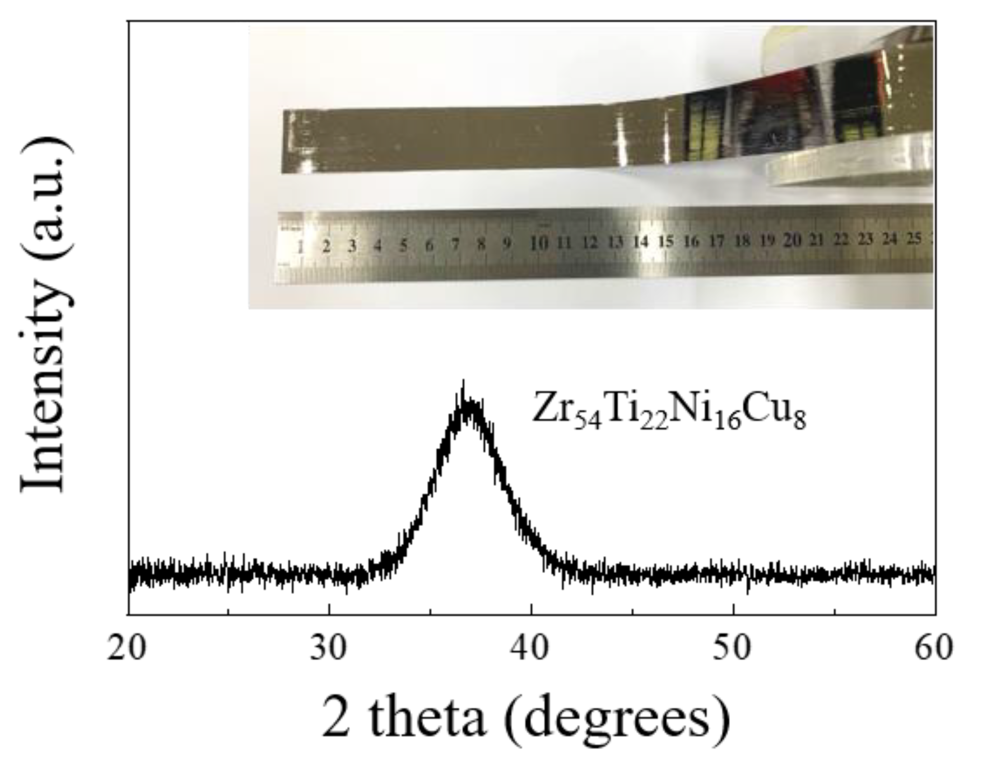
| Zr54Ti22Ni16Cu8 | 62.97 | 14.83 | 13.99 | 8.21 | 768 | 786 |
| Region | Zr | Ti | O | Ni | Cu | Al | V | Possible Phase |
|---|---|---|---|---|---|---|---|---|
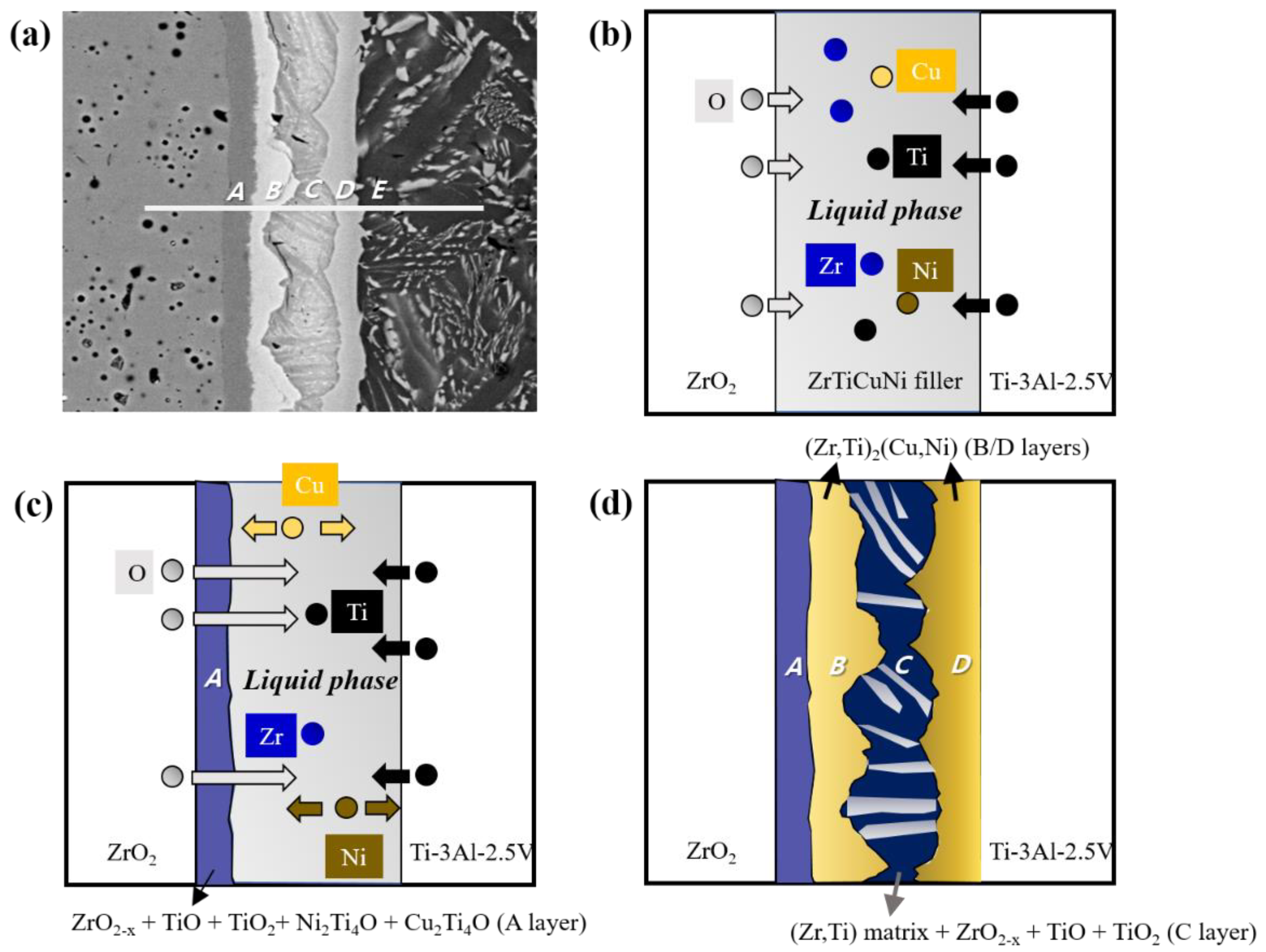
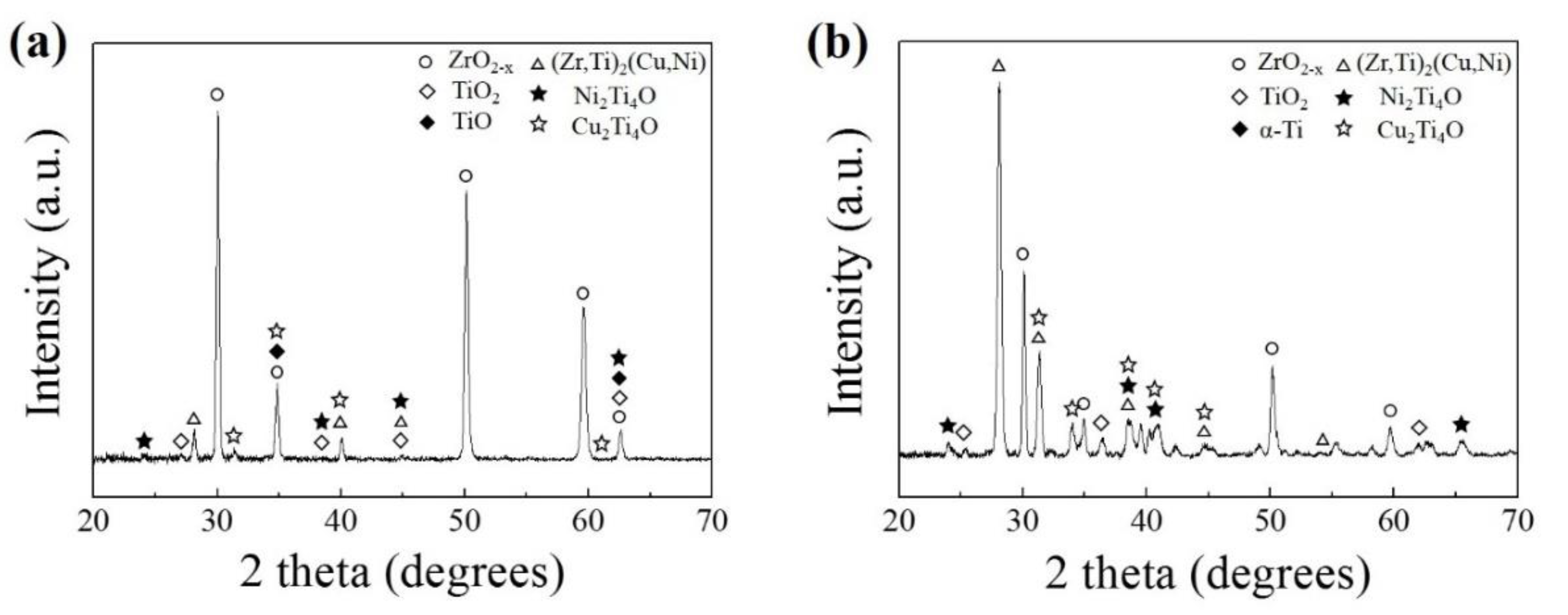
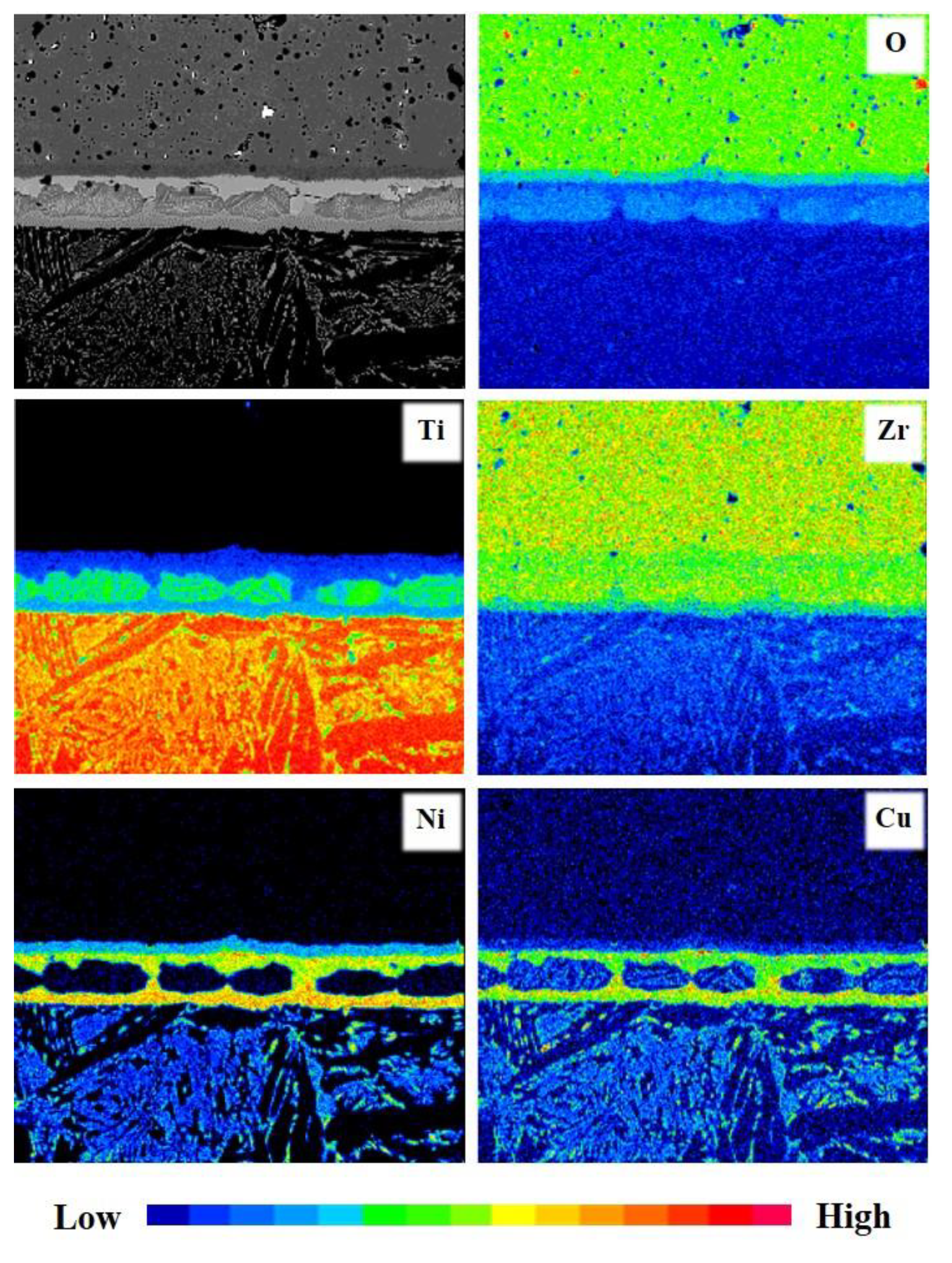
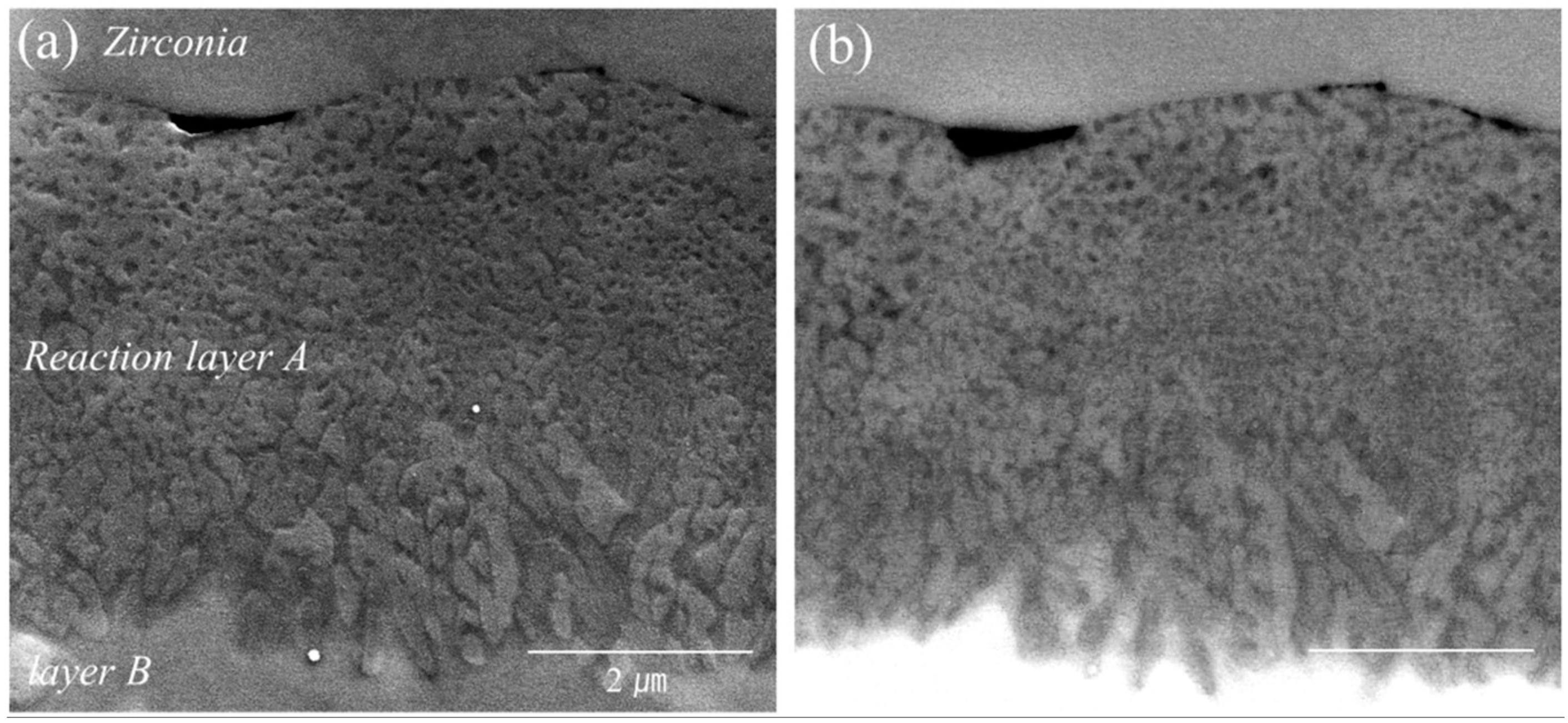
| A | 37.66 | 16.54 | 35.36 | 8.45 | 1.82 | 0.17 | - | ZrO2-x, TiO, TiO2, Cu2Ti4O, Ni2Ti4O |
| B | 40.77 | 25.07 | 8.32 | 17.31 | 7.22 | 0.92 | 0.39 | Zr-Matrix + (Zr,Ti)2(Cu,Ni) |
| C | 41.01 | 48.52 | 6.13 | 1.18 | 2.19 | 0.97 | - | (Zr,Ti)-Matrix + ZrO2-x + TiO + TiO2 |
| D | 26.15 | 37.34 | 3.77 | 18.63 | 7.16 | 6.06 | 0.89 | α-Ti-Matrix + (Zr,Ti)2(Cu,Ni) |
| E | 11.97 | 69.74 | 6.14 | 3.66 | 2.61 | 4.54 | 1.35 | acicular Widmanstäten structure |
© 2020 by the authors. Licensee MDPI, Basel, Switzerland. This article is an open access article distributed under the terms and conditions of the Creative Commons Attribution (CC BY) license (http://creativecommons.org/licenses/by/4.0/).
Share and Cite
Park, S.W.; Lee, H.; Lee, B.H.; Kim, T.H.; Kim, K.I.; Hong, S.A.; Kim, M.; Hyun, S.-K.; Ryu, G.H.; Kim, K.T. Effect of Interface Microstructure on Joint Strength of Zirconia/Titanium Alloy Brazed with Amorphous Zr-Ti-Ni-Cu Active Filler Metal. Metals 2020, 10, 718. https://doi.org/10.3390/met10060718
Park SW, Lee H, Lee BH, Kim TH, Kim KI, Hong SA, Kim M, Hyun S-K, Ryu GH, Kim KT. Effect of Interface Microstructure on Joint Strength of Zirconia/Titanium Alloy Brazed with Amorphous Zr-Ti-Ni-Cu Active Filler Metal. Metals. 2020; 10(6):718. https://doi.org/10.3390/met10060718
Chicago/Turabian StylePark, Sung Woo, Hyunjong Lee, Byung Hoon Lee, Tae Hwan Kim, Kyung Il Kim, Se Ah Hong, Minji Kim, Soong-Keun Hyun, Gwan Ho Ryu, and Kyung Taek Kim. 2020. "Effect of Interface Microstructure on Joint Strength of Zirconia/Titanium Alloy Brazed with Amorphous Zr-Ti-Ni-Cu Active Filler Metal" Metals 10, no. 6: 718. https://doi.org/10.3390/met10060718