Article

Fabrication and Mechanical Properties of Rolled Aluminium Unidirectional Cellular Structure

1
Faculty of Mechanical Engineering, University of Maribor, 2000 Maribor, Slovenia
2
National Institute of Technology, Kumamoto College, Yatsushiro 866-8501, Japan
3
Graduate School of Science and Technology, Kumamoto University, Kumamoto 860-8555, Japan
4
Faculty of Electrical Engineering, Mechanical Engineering and Naval Architecture, University of Split, 21000 Split, Croatia
5
International Research Organization for Advanced Science and Technology, Kumamoto University, Kumamoto 860-8555, Japan
6
Institute of Pulsed Power Science, Kumamoto University, Kumamoto 860-8555, Japan
*
Author to whom correspondence should be addressed.
Metals 2020, 10(6), 770; https://doi.org/10.3390/met10060770
Submission received: 12 May 2020 / Revised: 31 May 2020 / Accepted: 5 June 2020 / Published: 9 June 2020
(This article belongs to the Special Issue Cellular Metals: Fabrication, Properties and Applications)

Abstract

:
The paper focuses on the fabrication of novel aluminium cellular structures and their metallographic and mechanical characterisation. The aluminium UniPore specimens have been manufactured by rolling a thin aluminium foil with acrylic spacers for the first time. The novel approach allows for the cheaper and faster fabrication of the UniPore specimens and improved welding conditions since a lack of a continuous wavy interface was observed in the previous fabrication process. The rolled assembly was subjected to explosive compaction, which resulted in a unidirectional aluminium cellular structure with longitudinal pores as the result of the explosive welding mechanism. The metallographic analysis confirmed a strong bonding between the foil surfaces. The results of the quasi-static and dynamic compressive tests showed stress–strain behaviour, which is typical for cellular metals. No strain-rate sensitivity could be observed in dynamic testing at moderate loading velocities. The fabrication process and the influencing parameters have been further studied by using the computational simulations, revealing that the foil thickness has a dominant influence on the final specimen geometry.

1. Introduction

There is an ever-increasing demand for new multifunctional lightweight materials in advanced applications in engineering, transportation, and medicine, which can often be met by cellular metals. Their behaviour can be tailored [1] by combining the base material, porosity, morphology (size and shape of the cells, connectivity between cells) and topology (distribution of the cells within the material) according to [2]. Additionally, the behaviour can be tuned either by the partial [3] or full [4] infiltration of polymer filler into the cellular structure. These parameters and the manufacturing procedure [5] have to be carefully chosen to achieve required physical properties (e.g., stiffness, strength, energy absorption, conductivity) of cellular metals [6]. The main advantages of cellular materials and structures are a lightweight design, fire retardancy, efficient energy absorption, isolation and damping [5]. They can be used in various industrial applications (e.g., as sandwich structures, filters, heat exchangers, isolators, dampers, bearings, and energy absorbers [7]) due to their advantageous physical [8], biocompatible [9], and ergonomic characteristics [10].
Nevertheless, the production costs of cellular metals are high in general due to some technological problems that have yet to be solved. The current research and development trends are presently centred on the development of foam formation and stabilisation mechanisms, the investigation of advanced blowing constituents (agents), the optimisation of the production and the decrease of their market value [11]. The technological problems are mainly related to the control of the material structure since most existing technologies do not allow for precise control of the shape, size, and distribution of pores. This results in a scatter of physical and other characteristics of these materials and components. Some of the already existing manufacturing methods for different types of cellular structures—e.g., Metallic Hollow Sphere Structures [12], Kagome structures [13], auxetic structures [14], additively manufactured open-cell structures [15], Lotus-type [16] or Gasar [17] and UniPore structures [18], and syntactic foams [19,20]—allow for a higher level of regularity and reproducibility.
The recent development of unidirectional UniPore structures [21] enabled the production of unidirectional cellular metals with a nearly constant size of cells and the intercellular wall thickness through the length of the specimens. Furthermore, the cells are completely isolated, without gaps between each other [18] and advanced mechanical properties [22]. The fabrication method [23] is based on explosive welding phenomena of metal (e.g., copper [18], aluminium [24]) cylindrical pipes with circular cross-section assembly. The transversely isotropic UniPore cellular structure exhibits a promising combination of mechanical [25] and thermal behaviour [26]. The original fabrication of UniPore structures has shown only moderate welding conditions not forming a continuous wavy interface at some interface sections because of the changing collision angle [18]. Additionally, the fabrication consists of a tedious filling of expensive thin inner pipes (with a pipe diameter smaller than 3 mm and its wall thickness of approx. 0.2 mm) with a polymer to avoid complete compaction and its removal after fabrication. Due to these shortcomings, new fabrication methods have been considered. A new procedure to manufacture UniPore structures was proposed [27]. It consists of rolling a non-expensive copper foil with equally spaced spacer bars (made of acryl) placed on the foil and subsequent compaction by explosive detonation.
Herein, the fabrication and properties of novel rolled aluminium UniPore structures were analysed. The rolling of the non-expensive aluminium foil improved welding conditions and decreased handling time of the specimens before and after fabrication. Various rolled UniPore geometries have been fabricated and characterised by metallographic analysis and (quasi-static and dynamic) mechanical compressive testing for the first time. Additionally, the fabrication process was analysed in detail with computational simulations based on the finite element analysis.

2. Fabrication Method and Specimens

The fabrication method of the rolled aluminium UniPore structures is a convenient and cheaper method for manufacturing the UniPore cellular structures with unidirectional pores by using the aluminium foil (A1100-O). It consists of the following steps: (i) preparation of acrylic spacer bars by cutting the acrylic resin plate into rectangular shaped bars, (ii) positioning of the acrylic spacer bars on the aluminium foil in a uniform pattern with an offset of approximately 3 mm, (iii) tight rolling of the aluminium foil with acrylic resin spacer bars around the aluminium bar as the centre (core), (iv) insertion of the rolled foil into the outer aluminium pipe, (v) central insertion of the aluminium pipe with rolled foil into the PVC round container (height: 270 mm and diameter: 83 mm), (vi) filling the void space between the central aluminium pipe and container wall with the primary explosive (750 g), (vii) explosive ignition by an electric detonator (booster) to achieve explosive compaction of aluminium pipe and foil, (viii) removal of the acrylic bars by heating the recovered specimens.
The schematic illustration of the fabrication method and the explosive compaction (cylindrical) assembly is presented in Figure 1, while the physical properties of the components and the assembled specimens are listed in Table 1. The porosity of the specimens could be altered by changing the thickness of the outer pipe and by reducing the diameter of the inner aluminium bar.
The ammonium-nitrate based ANFO-A with the detonation velocity of 2.3 km/s and the bulk density of 530 kg/m3 was used as the primary explosive for manufacturing the rolled aluminium UniPore structure. The primary explosive was electrically detonated using a booster (10 g SEP explosive). Ignition of the primary explosive caused propagation of the detonation wave through the primary explosive. The detonation gas uniformly radially accelerated the outer aluminium pipe towards the centre of the specimen. The achieved velocity was high enough to allow for welding between surfaces of the outer pipe and aluminium foil. Stable welding conditions and inclination angle were similar to the already known explosive welding mechanism [28]. Furthermore, the explosive welding of clads is being characterised as cold pressure welding. The annealing effect, which would decrease the hardness, does not usually appear, and the increase in hardness is considered to be the result of the work hardening [22]. Figure 2 presents the cross-sections of the recovered specimens, while their geometrical properties (dimensions and porosity) are given in Table 2.
The shape and pore topology can be easily varied and adjusted for specific and individual applications by using the above-described fabrication method porosity (e.g., via wall thickness), dimensions (e.g., diameter).

3. Computational Analysis of the Fabrication Process

3.1. Computational Model

The computational simulations of the high-strain-rate deformation mechanism during fabrication of the aluminium UniPore structures were carried out to analyse the outer pipe’s acceleration during the fabrication and the deformation of the recovered specimens in more detail. The computational simulations of all four specimen types (Figure 3) were performed based on the following assumptions and simplifications: (i) two-dimensional computational models were used, (ii) the aluminium pipe, bar and foil were compressed without joining, and (iii) the geometry of the rolled foil was modelled with multiple concentric circles.
The aluminium and acrylic resin were discretised by the Lagrangian mesh, while the ANFO-A explosive has been modelled with the Eulerian finite elements. The computational simulation was based on the Euler–Lagrange interaction within the engineering code AUTODYN. To assure reliable results and reasonable computational times a finite element mesh convergence study was performed. The results showed the appropriate element size of 0.2 mm and 0.5 mm for the foil and aluminium bar, respectively. The Johnson–Cook constitutive equation [29] was applied for the aluminium (A1100-O) because it takes into account the strain-rate sensitivity and hardening effects. The relation between the pressure and volume of the aluminium and acrylic resin at a specific temperature was defined using the Mie–Gruneisen equation of state [30]. It is based on the shock Hugoniot equation and can be expressed as [31]:
P = p H + Γ   ρ ( e e H )
p H = ρ 0   c 0 2   μ   ( 1 + μ ) [ 1 ( s 1 )   μ ] 2
e H = 1 2 p H ρ 0 ( μ 1 + μ )
where P represents the pressure, Γ the Gruneisen coefficient, ρ the density, e the internal energy and μ = ρ / ρ 0 1 . The shock velocity ( U s )
U s = c 0 + s · u s
changes linearly (represented by the Hugoniot relation) with the particle velocity ( u p ). The parameters s and c 0 are experimentally determined material constants [31]. Parameters of the Mie–Gruneisen equation of state applied in the computational analysis are given in Table 3.
In the computational simulations, the ANFO-A was described as highly pressurised gas with an initial pressure of 0.939 GPa, a detonation velocity of 2.3 km/s, and a density of 530 kg/m3 [32].

3.2. Computational Results

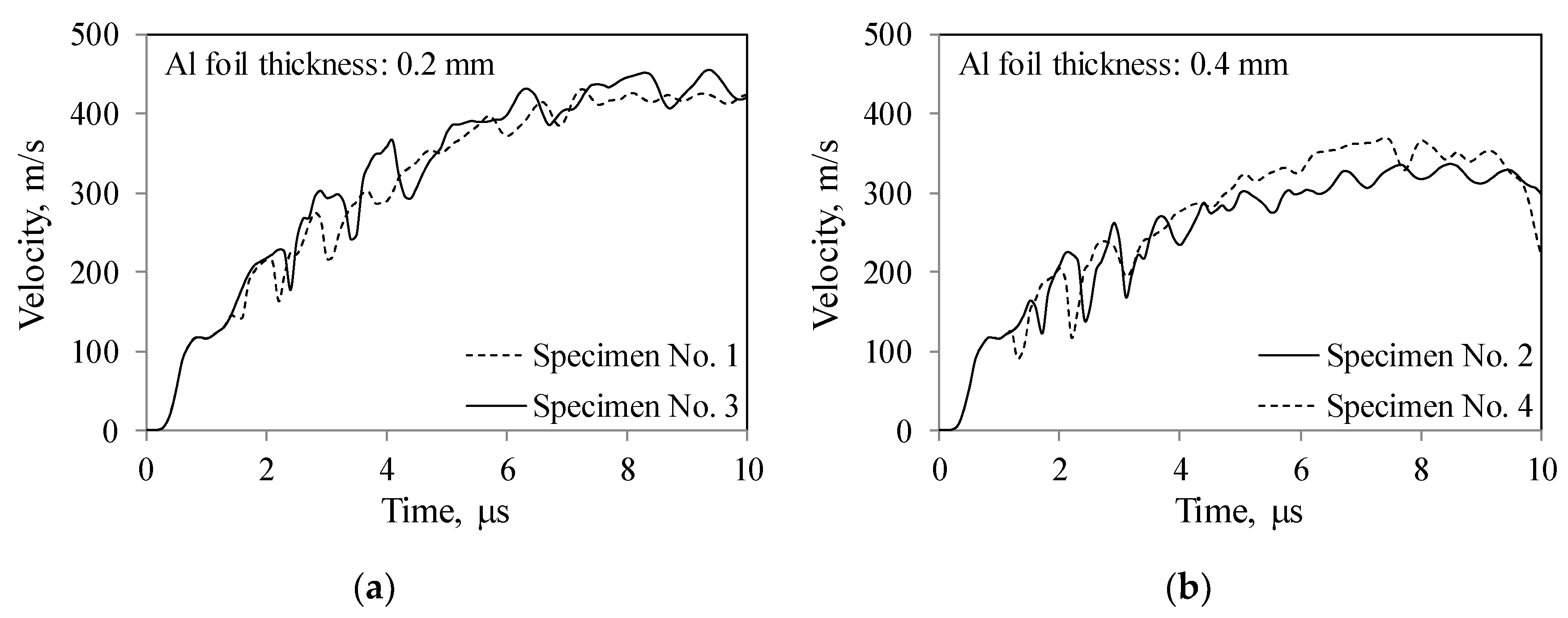
The diagrams in Figure 4 shows the of the outer pipe velocity V changes with time. The results based on the acrylic resin bar of 0.5 mm in thickness are represented with dotted lines, while the results based on the acrylic resin bar of 1 mm in thickness are represented with solid ones. It can be observed from the diagrams that the collision velocity is higher than 300 m/s, which is sufficient to obtain explosive welding [33]. The outer pipe velocity strongly depends on the aluminium foil thickness, while the influence of acrylic resin bar thickness is minimal.
The computationally estimated deformation process during the explosive compaction of all four specimen types is shown in Figure 5. The highly localised deformation during the explosive compaction can be observed. The primary effective plastic deformation occurs in areas around the acrylic bars, where the thin aluminium foil is locally bent.
The deformed shapes of the UniPore structures obtained by the computational simulations are presented in Figure 6. The computational results are in an excellent agreement with the actual specimens in terms of deformed shapes, which are shown in Figure 2. The deformation mechanism up to the impact between the foil surfaces and acrylic resin bars was thoroughly investigated by conducted computational analyses. However, it should be noted that the metal jet formation was not directly considered in the computational simulations.

4. Metallographic Analysis

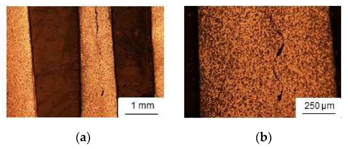
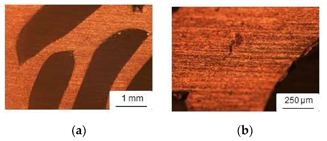
Metallographic analysis of the recovered specimens has been performed to determine the quality and suitability of the fabrication method. The specimens were prepared according to the standard metallographic methods (embedding in the epoxy resin, grinding, polishing, chemically etching). The microstructure of two perpendicular (longitudinal and transversal) cross-sections was analysed by the light microscopy using the optical microscope Nikon LV150N (Nikon, Tokyo, Japan). Figure 7 and Figure 8 show the metallographic images of the longitudinal and transversal cross-section, respectively.
A wavy interface between two colliding surfaces of the aluminium foil is represented in Figure 7, which assures a strong connection and good bonding between surfaces [33]. From the metallographic analysis, it can be concluded that the foil surfaces were welded at a sufficiently high velocity, despite a few places, where the surfaces might not be bonded completely.
The metallographic images in Figure 8 also show good bonding between the foil surfaces in the transversal cross-section and that the pores are separated and isolated between each other.

5. Compressive Experiments

5.1. Experimental Set-Up

The mechanical behaviour of manufactured rolled aluminium UniPore structures was evaluated in transversal direction by the quasi-static and dynamic (one specimen of the type No. 1, 2 and 3) compressive experimental tests using the universal testing machine (Instron 8801, Instron, Norwood, MA, USA). The velocity of the cross-head during the quasi-static and dynamic loading cases was set to 0.1 mm/s and 284 mm/s, respectively. Displacements and loading forces were measured during the compressive tests. At the same time, the deformation mechanism was captured by an HD video camera Sony HDR-SR8E (Sony, Tokyo, Japan) during the quasi-static tests, and the middle-wave infrared (IR) thermal camera FLIR SC 5000 (FLIR Systems, Wilsonville, OR, USA) during the dynamic tests. The IR thermography allows following the yielding, cracking and failure during the dynamic loading [34]. It has been already successfully implemented for studying the response of various cellular structures.

5.2. Experimental Results

The compressive deformation behaviour of the four specimen types subjected to quasi-static loading conditions is illustrated in Figure 9. A similar deformation behaviour can be noted for all cases. Initially, the porous part of the specimen is compressed, followed by the deformation of the specimen’s core. A strong interface bonding can be observed for the specimen No. 1 (aluminium foil thickness: 0.2 mm and acryl bar thickness: 0.5 mm). The bonds between the foil surfaces of the other three specimen types failed at larger strains, especially in case of the specimen No. 4 (aluminium foil thickness: 0.4 mm and acryl bar thickness: 1 mm).
Figure 10 shows the IR images of the deformation mechanism of specimens (No. 1, No. 2 and No. 4) during the dynamic tests. The interface between the foil surfaces tends to fail again in the specimen No. 4. However, the deformation mechanism seems to be similar for all specimen types. The porous structure starts to yield below and above the aluminium core with the plastification zone spreading through the specimen up to full densification. Furthermore, the explosive welding of clads is characterised as cold pressure welding.
The mechanical response in terms of force-displacement diagrams is shown in Figure 11. A compressive relationship typical for the cellular metals [2] can be observed in all cases. After the initial quasi-elastic region, the yield stress is reached, followed by a short stress plateau region. Then the force starts to build up gradually and reaches the densification displacement at approximately 14 mm (equal to the strain of 0.54), after which the force drastically increases (the porous structure above and below the core is wholly densified).
The measurements show a very consistent response (almost no deviation between specimens of the same type) up to the end of the plateau region. The deviation becomes prominent during the gradual force increase, which can be attributed to bending, buckling, and collapsing of the foil (intercellular walls) and the separation of the bonds between the foil surfaces.
Finally, the quasi-static and dynamic tests provided similar results. Thus, no strain-rate sensitivity was noted for the tested moderate strain-rates.

6. Conclusions

The existing UniPore structures with unidirectional pores have shown two main disadvantages: (i) moderate welding conditions, which result in a lack of a continuous wavy interface at some bonded sections, and (ii) the fabrication consists of filling the expensive thin inner pipes with a polymer to avoid complete compaction and its removal after fabrication. Explosive compaction has been applied for the first time to fabricate the rolled aluminium UniPore specimens. After rolling an aluminium foil with acrylic spacers (no additional filling and removal step of the polymer was required), the assembly was subjected to explosive compaction, which—due to the mechanism of explosive welding—resulted in a unidirectional cellular structure with longitudinal pores. The fabrication process and the influencing parameters have been studied in detail by use of computational simulations, revealing that the foil thickness has a dominant influence on the finial specimen geometry (shape). The computational results compare well to the actual specimens in terms of the specimens’ final shape. The metallographic analysis confirmed a strong bonding between the foil surfaces, which could be observed through the wavy interface, typical in the successful explosive welding. The compressive experiments showed a typical cellular metal response with excellent repeatability and a low deviation up to the end of the plateau region. Due to the moderate loading velocity, the dynamic compressive tests revealed negligible strain-rate sensitivity.
The future work should be focused on analysing a higher porosity by changing the thickness of the outer pipe and the rolled foil layer, and the diameter of the inner aluminium bar. Furthermore, it would be meaningful to perform a full strain-rate sensitivity study of the UniPore structures.

Author Contributions

Conceptualisation, K.H., Y.M. and Z.R.; methodology, K.H., Y.M. and Z.R.; software, M.N.; validation, M.N.; investigation, K.H., T.N., L.K.-O. and M.V.; data curation, M.N., T.N. and M.V.; writing—original draft preparation, K.H., Y.M., M.N., L.K.-O., Z.R. and M.V.; writing—review and editing, K.H., Y.M., M.N., L.K.-O., Z.R. and M.V.; supervision, K.H., Y.M. and Z.R.; project administration, K.H., Y.M. and Z.R. All authors have read and agreed to the published version of the manuscript.

Funding

This research was partially funded by the Slovenian Research Agency–ARRS, research core funding No. P2-0063 and the bilateral research project No. BI-HR/18-19-012.

Acknowledgments

The authors acknowledge the financial support from the Slovenian Research Agency–ARRS.

Conflicts of Interest

The authors declare no conflict of interest.

References

  1. Lefebvre, L.P.; Banhart, J.; Dunand, D.C. Porous Metals and Metallic Foams: Current Status and Recent Developments. Adv. Eng. Mater. 2008, 10, 775–787. [Google Scholar] [CrossRef] [Green Version]
  2. Ashby, M.F.; Evans, A.; Fleck, N.A.; Gibson, L.J.; Hutchinson, J.W.; Wadley, H.N.G. Metal Foams: A Design Guide; Elsevier Science: Burlington, MA, USA, 2000. [Google Scholar]
  3. Matsumoto, R.; Kanatani, S.; Utsunomiya, H. Filling of surface pores of aluminum foam with polyamide by selective laser melting for improvement in mechanical properties. J. Mater. Process. Technol. 2016, 237, 402–408. [Google Scholar] [CrossRef]
  4. Duarte, I.; Vesenjak, M.; Krstulović-Opara, L.; Ren, Z. Crush performance of multifunctional hybrid foams based on an aluminium alloy open-cell foam skeleton. Polym. Test. 2018, 67, 246–256. [Google Scholar] [CrossRef]
  5. Banhart, J. Manufacture, characterisation and application of cellular metals and metal foams. Prog. Mater. Sci. 2001, 46, 559–632. [Google Scholar] [CrossRef]
  6. Lehmhus, D.; Vesenjak, M.; de Schampheleire, S.; Fiedler, T.; Schampheleire, S.; Fiedler, T. From Stochastic Foam to Designed Structure: Balancing Cost and Performance of Cellular Metals. Materials 2017, 10, 922. [Google Scholar] [CrossRef] [Green Version]
  7. Hohe, J.; Hardenacke, V.; Fascio, V.; Girard, Y.; Baumeister, J.; Stöbener, K.; Weise, J.; Lehmhus, D.; Pattofatto, S.; Zeng, H.; et al. Numerical and experimental design of graded cellular sandwich cores for multifunctional aerospace applications. Mater. Des. 2012, 39, 20–32. [Google Scholar] [CrossRef]
  8. García-Moreno, F. Commercial Applications of Metal Foams: Their Properties and Production. Materials 2016, 9, 85. [Google Scholar] [CrossRef] [PubMed]
  9. Zhang, L.; Tan, J.; Meng, Z.D.; He, Z.Y.; Zhang, Y.Q.; Jiang, Y.H.; Zhou, R. Low elastic modulus Ti-Ag/Ti radial gradient porous composite with high strength and large plasticity prepared by spark plasma sintering. Mater. Sci. Eng. A 2017, 688, 330–337. [Google Scholar] [CrossRef]
  10. Harih, G.; Borovinsek, M.; Ren, Z.; Dolsak, B. Optimal Products’ Hand-Handle Interface Parameter Identification. Int. J. Simul. Model. 2015, 14, 404–415. [Google Scholar] [CrossRef]
  11. Duarte, I.; Banhart, J. A study of aluminium foam formation—kinetics and microstructure. Acta Mater. 2000, 48, 2349–2362. [Google Scholar] [CrossRef]
  12. Öchsner, A.; Augustin, C. (Eds.) Multifunctional Metallic Hollow Sphere Structures; Springer: Berlin, Germany, 2009; ISBN 978-3-642-00490-2. [Google Scholar]
  13. Lee, Y.-H.; Lee, B.-K.; Jeon, I.; Kang, K.-J. Wire-woven bulk Kagome truss cores. Acta Mater. 2007, 55, 6084–6094. [Google Scholar] [CrossRef]
  14. Novak, N.; Vesenjak, M.; Ren, Z. Auxetic Cellular Materials-a Review. J. Mech. Eng. 2016, 62, 485–493. [Google Scholar] [CrossRef] [Green Version]
  15. Soro, N.; Attar, H.; Wu, X.; Dargusch, M.S. Investigation of the structure and mechanical properties of additively manufactured Ti-6Al-4V biomedical scaffolds designed with a Schwartz primitive unit-cell. Mater. Sci. Eng. A 2019, 745, 195–202. [Google Scholar] [CrossRef]
  16. Nakajima, H. Fabrication, properties and application of porous metals with directional pores. Prog. Mater. Sci. 2007, 52, 1091–1173. [Google Scholar] [CrossRef]
  17. Shapovalov, V.I. Porous metals. MRS Bull. 1994, 19, 24–29. [Google Scholar] [CrossRef]
  18. Hokamoto, K.; Vesenjak, M.; Ren, Z. Fabrication of cylindrical unidirectional porous metal with explosive compaction. Mater. Lett. 2014, 137, 323–327. [Google Scholar] [CrossRef]
  19. Movahedi, N.; Conway, S.; Belova, I.V.; Murch, G.E.; Fiedler, T. Influence of particle arrangement on the compression of functionally graded metal syntactic foams. Mater. Sci. Eng. A 2019, 764, 138242. [Google Scholar] [CrossRef]
  20. Katona, B.; Szlancsik, A.; Tábi, T.; Orbulov, I.N. Compressive characteristics and low frequency damping of aluminium matrix syntactic foams. Mater. Sci. Eng. A 2019, 739, 140–148. [Google Scholar] [CrossRef]
  21. Hokamoto, K.; Torii, S.; Kimura, A.; Kai, S. Metal Pipe Joint Body and Manufacturing Method Thereof. Japanese Patent 5848016, 4 December 2015. [Google Scholar]
  22. Vesenjak, M.; Hokamoto, K.; Anžel, I.; Sato, A.; Tsunoda, R.; Krstulović-Opara, L.; Ren, Z. Influence of the explosive treatment on the mechanical properties and microstructure of copper. Mater. Des. 2015, 75, 85–94. [Google Scholar] [CrossRef]
  23. Nishi, M.; Oshita, M.; Ulbin, M.; Vesenjak, M.; Ren, Z.; Hokamoto, K. Computational Analysis of the Explosive Compaction Fabrication Process of Cylindrical Uni-directional Porous Copper. Met. Mater. Int. 2018, 24, 1143–1148. [Google Scholar] [CrossRef]
  24. Hokamoto, K.; Shimomiya, K.; Nishi, M.; Krstulović-opara, L.; Vesenjak, M.; Ren, Z. Fabrication of unidirectional porous-structured aluminum through explosive compaction using cylindrical geometry. J. Mater. Process. Technol. 2018, 251, 262–266. [Google Scholar] [CrossRef]
  25. Vesenjak, M.; Hokamoto, K.; Sakamoto, M.; Nishi, T.; Krstulović-Opara, L.; Ren, Z. Mechanical and microstructural analysis of unidirectional porous (UniPore) copper. Mater. Des. 2016, 90. [Google Scholar] [CrossRef]
  26. Fiedler, T.; Borovinšek, M.; Hokamoto, K.; Vesenjak, M. High-performance thermal capacitors made by explosion forming. Int. J. Heat Mass Transf. 2015, 83, 366–371. [Google Scholar] [CrossRef]
  27. Vesenjak, M.; Hokamoto, K.; Matsumoto, S.; Marumo, Y.; Ren, Z. Unidirectional porous metal fabricated by rolling of copper sheet and explosive compaction. Mater. Lett. 2016, 170, 39–43. [Google Scholar] [CrossRef]
  28. Meyers, M.A.; Murr, L.E. Shock Waves and High-Strain-Rate Phenomena Effects in Metals; Springer: New York, NY, USA, 1981. [Google Scholar]
  29. Mayers, M.A. Dynamic Behavior of Materials; Wiley Interscience: New York, NY, USA, 1994. [Google Scholar]
  30. Marsh, S.P. Los Alamos Scientific Laboratory Report; LA-4167-MS; University of California Press: Oakland, CA, USA, 1969. [Google Scholar]
  31. Marsh, M.A. LASL Shock Hugoniot Data; University of California Press: Berkeley, CA, USA, 1980. [Google Scholar]
  32. Fujita, M.; Chiba, A.; Fukuda, I.; Osaka, H.; Baba, F.; Manabe, T. An analysis of multilayered explosive bonding process. Kyogyo-kayaku 1987, 48, 176–182. (In Japanese) [Google Scholar]
  33. Crossland, B. Explosive Welding of Metals and Its Application; Oxford University Press: Oxford, UK, 1982; Volume 8, p. 233. [Google Scholar]
  34. Krstulović-Opara, L.; Surjak, M.; Vesenjak, M.; Tonković, Z.; Kodvanj, J.; Domazet, Ž. Comparison of infrared and 3D digital image correlation techniques applied for mechanical testing of materials. Infrared Phys. Technol. 2015, 73, 166–174. [Google Scholar] [CrossRef]
Figure 1. (a) Schematic preparation of the specimens and (b) experimental production assembly.
Metals 10 00770 g001
Figure 2. Cross-sections of the fabricated specimens.
Metals 10 00770 g002
Figure 3. A two-dimensional computational model of the aluminium UniPore specimens.
Metals 10 00770 g003
Figure 4. Velocity variation of the outer aluminium pipe during explosive compaction: (a) foil thickness 0.2 mm and (b) foil thickness 0.4 mm.
Metals 10 00770 g004
Figure 5. Simulation of the deformation process during explosive compaction of the four aluminium UniPore samples (Table 1) with annotated effective plastic strain.
Metals 10 00770 g005
Figure 6. Computationally predicted final deformed shapes of the four analysed specimen configurations (Table 1).
Metals 10 00770 g006
Figure 7. Metallographic images of the longitudinal cross-section of UniPore specimen. (a) lower magnification; (b) higher magnification.
Metals 10 00770 g007
Figure 8. Metallographic images of the transversal cross-section of UniPore specimen. (a) lower magnification; (b) higher magnification.
Metals 10 00770 g008
Figure 9. Transversal compressive testing of rolled aluminium UniPore structure.
Metals 10 00770 g009
Figure 10. IR thermography images of the dynamic loading sequence (strain increment: ~0.15): (a) Specimen No. 1; (b) Specimen No. 2; (c) Specimen No. 4.
Metals 10 00770 g010
Figure 11. Compressive force-displacement curves in the transversal direction: (a) foil thickness 0.2 mm and (b) foil thickness 0.4 mm.
Metals 10 00770 g011
Table 1. Physical properties of the prepared aluminium UniPore specimens.
Specimen
Type
Outer Pipe Diameter
(mm)
Length
(mm)
Internal StructureEstimated Porosity
(%)
Al Core Diameter
(mm)
Al Foil Thickness
(mm)
Acrylic Bar
Thickness
(mm)
Quantity
(-)
No. 130/24210100.20.56716.5
No. 20.40.5409.4
No. 30.21.03518.1
No. 40.41.03115.0
Table 2. Properties of the recovered specimens.
Specimen TypeNumber of Recovered Specimens
(-)
Average Diameter
(mm)
Average
Height
(mm)
Average Mass
(g)
Achieved Average Porosity (%)
No. 1426.211.012.815.5
No. 2426.211.914.99.3
No. 3126.310.412.717.5
No. 4426.010.412.315.0
Table 3. Values for the Mie–Gruneisen equation of state.
MaterialReference Density
ρ 0
(kg/m3)
Gruneisen Coefficient
Γ
(-)
Speed of Sound
c 0
(m/s)
Material Constant
s
(-)
A1100-O27071.953861.339
Acrylic resin11860.9725981.516