Fabrication of Saddle-Shaped Surfaces by a Laser Forming Process: An Experimental and Statistical Investigation


1
Department of Mechanical Engineering, Arak University of Technology, Arak 38181-41167, Iran
2
Center for Mechanical Technology and Automation, Department of Mechanical Engineering, University of Aveiro, Campus de Santiago, 3810-183 Aveiro, Portugal
*
Author to whom correspondence should be addressed.
Metals 2020, 10(7), 883; https://doi.org/10.3390/met10070883
Submission received: 9 June 2020
/
Revised: 26 June 2020
/
Accepted: 1 July 2020
/
Published: 3 July 2020
(This article belongs to the Special Issue Numerical and Experimental Advances in Innovative Manufacturing Processes)
Abstract
:Laser forming is a powerful tool for fabricating complicated shapes economically. The pattern of laser movement (irradiating scheme) has an essential effect on the shaped form. In this article, the forming of a saddle-shaped surface will be investigated experimentally by the laser forming process. A spiral irradiating scheme is implemented to manufacture a saddle-shaped surface. The main idea of this study is the investigation of the simultaneous variations of the process parameters and their effect on the curvature of the final part. The process parameters of the study are the spiral pitch, number of spiral passes, and movement pattern (In-to-Out or reversely Out-to-In scanning path). The response surface methodology is selected for experimentation. The measurement of the deformation results shows that the deformations of laser-formed saddle-shaped surfaces decrease with an increase in the spiral pitch of the path. Additionally, the deformations of the saddle-shaped surface increase by increasing the number of spiral passes. The results demonstrate that the pattern movement has little effect on the deformations of laser-formed saddle-shaped surfaces and an Out-to-In spiral pattern movement is advised. At last, the proper input variables to obtain the maximum value of displacements for the saddle point are determined (10 mm spiral pitch, three spiral passes, and Out-to-In pattern movement).
1. Introduction
Complex-shaped surfaces are used in different industries. Shipbuilding is one of the industries which need complicated surfaces, especially saddle-shaped surfaces. Mechanical-based forming processes and heat-based forming processes can produce a complex shape [1]. Among the heat-based forming processes, flame forming and laser forming processes are two conventional manufacturing processes which are used for the fabrication of doubly curved sheets. In heat-based forming processes, the sheet receives a heat flux, and the inhomogeneous deformation of the plate is made due to the shrinkage strain caused by the heating and the subsequent cooling in the sheet metal. So, a curved sheet is produced. The laser beam prepares a heat source that can be used for welding (laser beam welding (LBW)) and machining (laser beam machining (LBM)).
The highly concentrated power of the irradiated beam can melt or evaporate the material in LBW and LBM processes. However, if the applied power is restricted to low magnitudes, the beam can be used for forming curved surfaces or surface treatments (peening). In the laser forming of sheet metals, the beam irradiates the surface of the blank. The determination of the irradiation path is complicated. A laser beam is a non-contact tool without external forces, and the relation between the heating and deformation is complex. For the fabrication of a specified shape, different solutions may exist [2]. When the laser beam irradiates the blank surface, the laser energy is absorbed and increases the temperature of a small area of the surface. The elevated temperature on the top surface creates a temperature gradient along the thickness direction, and the layers near to the surface expand. The deformation induces a thermal expansion (thermal stress) and, consequently, compressive residual stresses. After passing the laser beam, the surface is quickly cooled and leads to thermal contraction and shrinkage. The shrinkage leads to local bending [3]. Line scanning results in single-curved surfaces, but for double-curved surfaces, a more complicated irradiating algorithm is needed [4,5,6]. Ship hull components, airplane fuselages and automotive bodies are complicated curved components for which manufacturing is limited to 2D laser forming and a 3D scanning pattern is needed. Cheng et al. [2] present an approach for the process design of the laser forming of thin plates with doubly curved shapes.
The method consists of calculating the in-plane strain and bending strain required to form the shape using ABAQUS software. The relation between the curvature and heating condition is determined by a lumped method, and the scanning path is determined. Keisuke et al. [7] investigated the laser forming of curved surfaces. The forming of the sheet is done according to the definition of the maximum and minimum curvature lines as the scanning paths, which are implemented in shipbuilding industries. A Bezier surface is manufactured successfully. Yu et al. [8] presented an algorithm for the fabrication of a 3D smooth continuous curved surface from a flat sheet. The minimum required strain distribution is determined by solving a nonlinear programming problem and then the optimal deformation is obtained. This article helped the researchers to develop the forming processes for the fabrication of curved surfaces by laser forming, laser shock forming or flame forming.
Chakraborty et al. [9] studied the formation of a bowl-shaped surface with radial laser scan lines using finite element analysis and experimental measurement. The radial laser irradiation scheme leads to tangential shrinkage in the circular blank, the shrinkage leads to localized buckling about the radial scan lines and the bowl shape is manufactured. Liu and Yao [10] offered a methodology for the laser formation of thin sheets according to finite element method (FEM) calculations. The strain field decomposed into in-plane and bending strains and the laser scanning paths were selected perpendicular to the averaged principal minimum strain direction. The heating conditions were determined according to the ratio of in-plane and bending strain magnitude. Two typical doubly curved shapes, a pillow shape and a saddle shape, were manufactured according to the developed approach. Na and Kim [11] in 2008 and Kim and Na [12] in 2009, studied the formation of sheet metal by a laser beam. A new method for the 3D laser formation of sheet metal was developed according to the use of geometrical information. In this method, the formation curve decomposed into several pieces of straight lines, and the formation points were the connection points of each straight line. Then, by using CAD/CAM approaches, the shrinkage and bending data were extracted, and the laser formation of a 3D surfaces was carried out using the finite element calculation of the displacement. Gao et al. [13] investigated the fabrication of 3D surfaces by laser formation based on a reverse analysis. The reverse analysis consisted of determining the required strain–displacement field to manufacture a specified shape from a flat initial blank and calculating the laser scanning patterns. By using COMSOL Multiphysics software, the optimal irradiation patterns and laser forming parameters were determined to manufacture a specified generic ship hull shape.
Imani Shahabad et al. [14,15] investigated the effect of the laser forming process (laser power, scan speed, beam diameter and sheet thickness) in the fabrication of a dome-shaped surface. A spider scanning strategy was used for manufacturing. By using the design of experiments (full factorial design) and analysis of variance (ANOVA), a regression equation was obtained for the determination of the dome height of the formed sheet. The results show the dome height increased with increasing laser power, increasing line energy, increasing heat flux, decreasing beam diameter, decreasing thickness and decreasing scan speed. Shen et al. [16,17] presented a scan strategy for the laser formation of double-curved shapes from single-curved shapes. By optimizing the strain energy and utilizing the minimum energy principle, the required strain distribution was calculated using finite element analysis. Then, the laser irradiation condition was determined by comparing the geometrical difference between the saddle shape and cylinder surfaces. The proposed method can produce complicated 3D shapes effectively. Das and Biswas [4] and Dixit et al. [18] published review papers on laser formation in 2018 and 2015, respectively. The literature survey shows that several numbers of researchers studied the laser formation process and suggested approaches for process design, control and optimization. The temperature field determination, thermomechanical analysis and fabrication of curved surfaces, along with soft computing approaches, are interesting for researchers. The development of mathematical models and optimization strategies are needed to describe the effect of the process parameters.
Wang et al. [19] explored deformation under the laser curve scanning of a three-layer stainless steel composite plate. A 3D nonlinear model was created in ABAQUS software for a three-layer stainless steel composite plate. Indirect coupling was employed to simulate the temperature field and the deformation field in the laser formation process, and a double curvature deformation was created in the sheet by laser curve scanning. The laser power and scanning speed were the main process parameters. Gisario and Barletta [20] studied the laser formation of fiber–metal laminates (FMLs) by laser formation. The effect of the laser formation parameters (the applied power, scanning speed and number of passes) was investigated to manufacture a complex shape on FMLs. The experimental results showed that specified curvatures could be obtained by a proper set-up and that increasing the number of irradiating passes leads to the thermal relaxation of the metal and then a decrease in bending angles. The failure analysis shows that interfacial delamination and the thermal alteration of the layers are two leading causes of failure and restriction in the formation.
Maji et al. [21] studied the formation of a dome-shaped surface by a cross scan strategy (axial and diagonal scans). Axial scans are parallel to the free edge of the samples, and diagonal scans are at a 45° angle. A statistical regression was used to determine the effectiveness of the process parameters (laser power, scan speed and spot diameter). Safari and Farzin [22] investigated the laser formation of a saddle shape experimentally. The experimental results show that this proposed spiral irradiating scheme is an appropriate and powerful method for the fabrication of saddle-shaped surfaces. The effects of the process parameters, including the pitch of the spiral path, the number of spiral passes and the scanning pattern, were investigated individually. Safari and Mostaan [23] fabricated a cylindrical surface by laser beam irradiation along several straight lines. By using the FEM simulation and analytical method, the process parameters for forming a specific cylindrical surface was determined. The required number of irradiating lines was determined according to the proposed analytical method by the authors. Table 1 compares the irradiation scheme, material and the dimension of the formed curved sheets. As can be seen, the researchers used different laser powers, laser spot diameters and scanning speeds. The wide variety of the applied laser parameters for the formation of curved shapes shows that a precise calculation is needed to obtain the desired shape. In the current work, the applied laser power is relatively low in comparison with other research.
The literature survey and data of Table 1 show that scanning strategy has a considerable effect on the final curvature of formed surfaces. Different materials, different scanning strategies and different laser irradiation parameters can be seen in the published literature. In this work, the laser formation of a saddle-shaped surface will be investigated experimentally by the spiral irradiating scheme. The selection of process parameters is the primary key for production, but the choice is not possible before determining the effect of the input parameters on the output variable. The response surface methodology is used for designing the experiments and identifying the impact of the process parameters. The main novelty of this work is the consideration of the simultaneous variations of the process parameters, which will explain the interaction of the process parameters. The effects of the spiral parameters, including the spiral pitch, the number of spiral passes and the movement pattern (In-to-Out or Out-to-In spiral path), on the deformation of laser-formed saddle-shaped surfaces are determined. In a recent publication [22] of one of the authors, the effects of the process parameters were investigated individually. The one factor at a time (OFAT) method was implemented to determine the impact of process parameters by [22], which is not a perfect method for a comprehensive investigation. In the OFAT method, one factor is changed and the others remain constant, while in practice, the variation of the parameters and their interactions influence the output variation. So, in this article, the Response Surface Method (RSM) method is used for the design of the experiments, and by using analysis of variance (ANOVA), a regression equation is proposed. Additionally, using an optimization procedure, the best values of input parameters for obtaining a saddle-shaped surface with maximum curvatures are selected.
2. Materials and Methods
To form the flat blanks, a CO2 laser is implemented—the maximum power of the used laser is 150 Watts (continuous irradiation). The initial blank is a mild steel square blank (100 × 100 mm2) with 0.85 mm thickness. Table 2 shows the chemical composition of mild steel. The concentration of the alloying element is low, and the steel can be called low alloy steel. The initial blank is cut from an annealed sheet, and the local hardening of materials at lateral edges is neglected. The laser beam absorption is essential in laser formation. Surface conditions, such as surface roughness, an oxide layer and surface pollutions, meaningfully affect the laser beam reflection and absorption. Due to the reflection of the beam, improper formation may happen. So, the initial blanks are firstly washed by pure acetone and then the surface of it is properly coated with graphite. The coating helps to improve the laser beam absorption. Figure 1a shows two laser-formed saddle-shaped surfaces produced with spiral patterns with different pitches. These complicated shapes are laser formed with laser power of 100 Watts, a beam diameter of 1 mm and a laser scanning speed of 400 mm/min.
It should be noted that the curvature values for the formed saddle-shaped surface are essential parameters that should be checked after the laser formation process. However, as shown in Figure 1b, in this paper, the displacements of sample point H are measured and used for the investigation of the deformations of the saddle-shaped surface manufactured by the laser formation process. An Easson ENC-565 coordinate measuring machine (EASSON Inc., Jiangsu, China) is used for measuring the displacements of sample point H on the saddle-shaped surface. The resolution of the measurement machine is 0.5 μm. The center point of the sheet (point H) is essential in the investigation. The saddle-shaped surface has two different curves (anticlastic curvature). Point H is the intersection of the bends, and the height of sample point H increases by decreasing the curvature radius. Like many kinds of research in this field, the displacement of sample point H is measured for the determination of curvature. The curvature radius can be calculated by knowing the width of the sheet and the difference in height between the sample point H and the lateral edge of the sheet. To find the curvature of the formed surface and also to determine the best operating conditions to maximize the curve, it is necessary to do the experimental tests very carefully and according to a specified plan.
The response surface methodology (RSM) is the proper design of experiments (DOE) tool to use. A bilinear regression equation predicts the curvature of the saddle-shaped surface by the RSM. Twenty-two experiments were conducted at a constant power of the laser beam (Table 3). The results of the measurements are shown. The process parameters included in the study are the spiral pitch, the number of spiral passes and the movement pattern (In-to-Out or Out-to-In spiral movement). The levels of the process parameters defined (or coded) in Table 3 are shown and described in Table 4. The levels of the input parameters are selected according to the dimension of the sheet and the available equipment. The start and endpoints of the spiral path are constant. The spiral pitch and the number of passes can be increased, but the levels are restricted to the shown values.
It should be noted that the direction of the spiral path is essential and the laser beam can scan the spiral path from the inside to the outside of the sheet (In-to-Out spiral movement) or move from the outside to the inside of the sheet (Out-to-In spiral movement). The height of sample point H is an important parameter for finding or controlling the curvature and it is located at the center point of the laser-formed saddle-shaped surface. The curvatures in the in-plane coordinate system differ from each other and an anticlastic curvature is obtained after formation. The interaction of the anticlastic curvatures (saddle point) is the center point of the sheet. The mathematical definition of curvature, as the second derivation of position, is not used in assessing the curvature of the formed blanks. In most of research, the displacement of the center point is used for comparison. The curvature radius can be predicted by knowing the width of the blank and the height of the sample point H, but due to high uncertainty in prediction, it is preferred to use the displacement of the center point as the assessing parameter.
Analysis of variance (ANOVA) is a powerful tool for estimating the goodness of fit of the model. Fisher developed ANOVA in the early 1920s. The ANOVA method is an appropriate procedure for testing the equality of several means with low effort. ANOVA is probably the most useful technique in the field of statistical inference. The name analysis of variance is derived from a partitioning of the total variance (sum of squares) in the data into two pieces: (1) the sum of squares of the differences between the level averages and the grand average (level mean) and (2) the sum of squares of the differences of observations within levels from the level average (random error) [24]. By calculating the variance between the fitted model and the measured experimental result, the importance and effectiveness of the process parameters and the interaction between them can be determined.
3. Results and Discussion
3.1. Analysis of Variance
The last column of Table 3 shows the measured displacements of sample point H in laser-formed saddle-shaped surfaces, and by using Minitab software, the ANOVA results for the DOE are presented in Table 5.
The first step in the proposition of a regression model is the determination of the input variables. According to the data of Table 5, a regression equation is obtained. But after checking the equation, it is observed that the error of estimation is high because of the high magnitude of the P-value for the spiral pattern (P) irradiation scheme. The P-value is used in hypothesis tests to determine whether or not to reject a null hypothesis. In the null hypothesis, it is assumed that there is no difference between the levels of each factor. The P-value is the probability of obtaining a test statistic that is at least as extreme as the actual calculated value. If the P-value is less than 0.05, the null hypothesis is rejected and the parameter has significant effect on the output parameter. After analyzing the result of ANOVA, it is decided to express two different regression equations for the different beam pattern movements. Equations (1) and (2) show the regression equation between the process parameters (spiral pitch and number of spiral passes) and displacements of sample point H in laser-formed saddle-shaped surfaces for In-to-Out and Out-to-In spiral pattern movements, respectively.
The proposed equation is the full quadratic equation, neglecting the interaction between the input parameters. Equation (1) describes the displacement of sample point H for the In-to-Out spiral pattern movement. The spiral pitch has a negative role and by increasing the spiral pitch, the displacement of sample point H decreases while the number of spiral passes has a positive role and increases the curvature. A similar trend is observed for the Out-to-In spiral pattern movement. The coefficient of N is higher for Equation (2), which shows that the number of spiral passes has a higher influence on the Out-to-In spiral pattern movement. The coefficients are very similar in Equations (1) and (2), and the difference between the In-to-Out and Out-to-In spiral pattern movement is negligible. The effect of the interaction for spiral pitch and the number of passes is low and neglected. Table 6 shows the ANOVA test results for the developed model. As can be seen in the analysis of variance results, the linear model and square of the input parameters have a significant effect on the output, and the impact of the interaction of the input parameters can be neglected. In most of the studies and references, the authors focus on the variation of one factor at a time. Imani Shahabad [14] used ANOVA for the prediction of dome height and proposed an equation with 11 terms for the calculation of the curvature of AA6061-T6 aluminium alloy. Maji et al. [21] carried out a similar study on the formation of dome-shaped surfaces from an AISI 304 stainless steel blank. The process parameters of the investigation were laser power, scan speed and spot diameter, and a regression model was developed to predict the dome height. Additionally, an artificial neural network was made to predict a particular dome height. Both of the works manufactured a dome shape with spider and cross scanning paths. The use of the spiral irradiation scheme and the fabrication of saddle-shaped surfaces is the main novelty of current work.
The adjusted (partial) sums of squares (Adj SS) and the adjusted mean squares (Adj MS) show the measure of variation or deviation from the mean. The curve-fitting quality can be determined by the R2 value (coefficient of determination), which in this study is 97.73%. So, the quality of the fitting is excellent. If the P-value is less than 0.05, this shows that the parameter is a significant factor and changes the output noticeably. So, the results of Table 6 indicate that the linear and quadratic terms for the developed model are substantial. Figure 2 shows the residual plots (the difference between the experimental results and predicted regression model) for the displacements of sample point H.
The residual plot of displacements in Figure 2 shows that the difference between the experimental results (dots in Figure 2) and the regression model (line) is in a restricted band (±0.2). Additionally, the frequency and observation order shows that no specific pattern exists, so the errors are distributed normally. The coefficient of determination “R2” is calculated according to the residual values and determines the difference between the predicted and experimental values. The value of R2 equals 1 for a perfect statistical model. The R2 coefficient is 0.9773 for the regression model and specifies that the regression model can predict the displacement of point H with a 97.73% accuracy, and only 2.27% of uncertainty may happen. So, Equations (1) and (2) have excellent accuracy and goodness of fitt for the range of parameters studied.
3.2. Mean Effects of Manufacturing Parameters
It is possible to determine the effect of the process parameters on the output by using ANOVA. Figure 3 shows the main effect plot for the displacements of sample point H. The effects of different process variables are determined independently from each other.
Figure 3 shows that the displacement of sample point H decreases by increasing the spiral pitch, and the curvature of the formed surface decreases. The travel speed of the laser beam is constant, so by reducing the spiral pitch, higher heat fluxes are received by the sheet. The higher irradiation length leads to higher plastic deformation, and the vertical displacement of sample point H is increased. The ANOVA results show that the displacement of the saddle point (sample point H) increases by increasing the number of spiral passes. By repeating the passes, the sheet receives more heat fluxes, and the sheet deforms again, and higher curvature values are obtained. The movement pattern has little effect on the curvature. The In-to-Out movement pattern leads to a lower curvature, and the Out-to-In movement pattern can fabricate a slightly higher curvature sample. This difference is due to the geometrical constraint, which exists at the coincident point of the laser beam and sheet.
The main effect plot determines the effects of the process variables independently. However, by plotting the response surface of the variables, the effects of interactions between the parameters can be determined. Figure 4 demonstrates the contour plot of the two main influencing process parameters (spiral pitch and the number of spiral passes) on the displacement of sample point H. The counterplot belongs to the Out-to-In spiral pattern movement.
Figure 4 shows that the displacement of sample point H increases with an increase in the number of spiral passes. It also increases with a decrease in spiral pitch. It should be noted that the spiral pitch and the number of passes have a positive effect. Consequently, their interaction leads to higher curvatures and higher displacements of sample point H due to inducing more heat flux into the sheet.
3.3. Optimized Condition
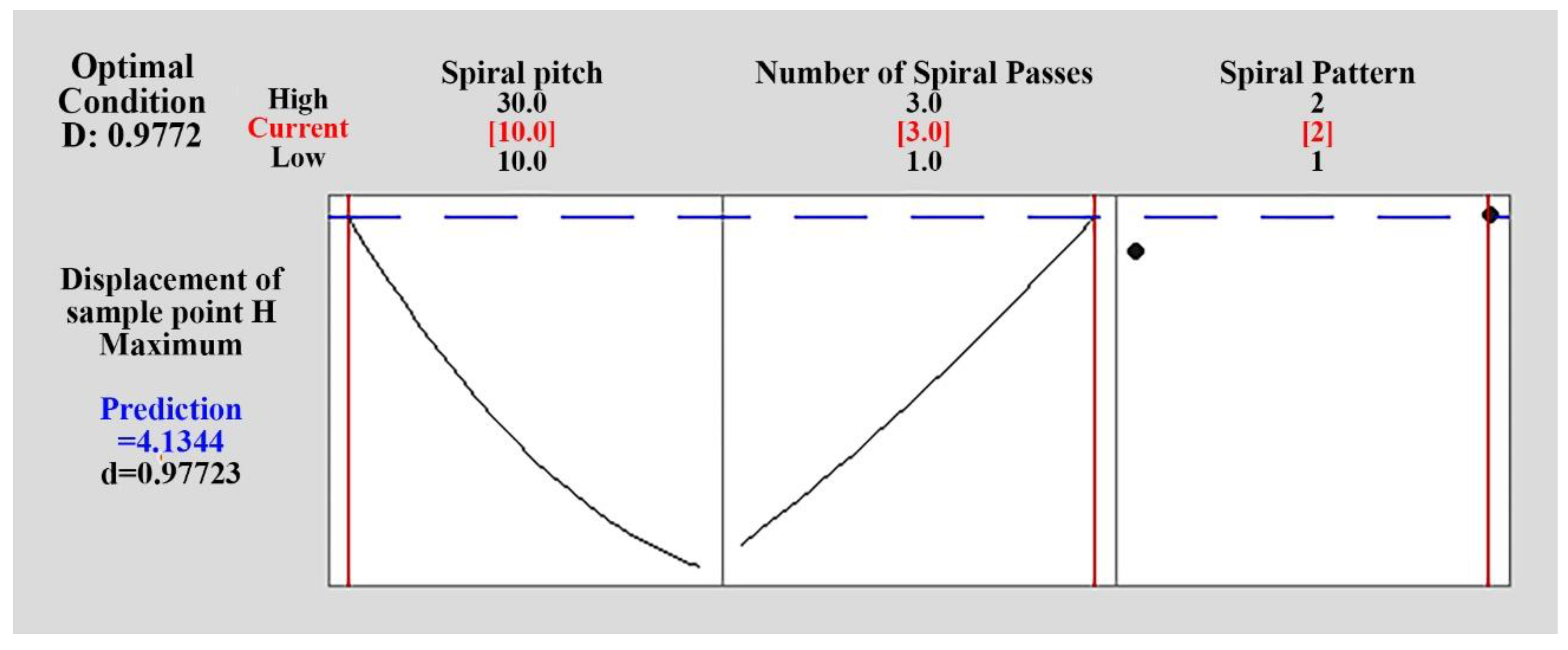
The optimization of input variables to obtain the maximum value of displacements of sample point H was carried out. Computing the maximum amount of displacement of sample point H from the model and taking into account the desirability limit, the optimization result is shown in Figure 5. It is shown in Figure 5 that for attaining the maximum value of displacement of sample point H, the spiral pitch, the number of spiral passes and spiral pattern should be adjusted to 10 mm, three passes and the Out-to-In movement pattern, respectively. The results show that by applying the optimized condition, a saddle-shaped sheet with a 4.13 mm displacement of sample point H is manufactured. By checking the performed experiments in Table 3, it can be seen that experiment #16 was done according to the optimized condition. The displacement of sample point H is 4.19 mm, and a 1.4% error exists in the prediction of the optimized condition. The maximum value of the displacement of sample point H may increase at a higher level of irradiation or reduced spiral pitches. The optimized condition is derived from the range of the process parameter levels. If the values of spiral pitch and the number of spiral passes exceed the range suggested in Table 4, the accuracy of Equations (1) and (2) may be decreased.
Finally, it should be noted that the design of experiments (DOE) method helps researchers to understand the effectiveness of the process parameters more easily. The relationships between the input parameters and the output variables are obtained with a reduced number of experimentations and lower costs. Due to the basics of DOE, it is possible to use the obtained equations of the regression model in the range of the process parameter variation. Besides, the equations are useful for out of range variation, if no essential changes have happened in the process. The ANOVA results and the proposed Equations (1) and (2) are developed accordingly. For example, the predicted optimum conditions for input parameters are compared with the used parameters in this work. As can be seen in the optimization section, good accuracy is obtained, and this verifies the transferability and validity of the implemented methods in this work.
Further experimentation is needed to concurrently consider the laser beam parameters (power, diameter, scan speed), spiral characteristics (pitch, length, number of passes, movement pattern and superposition of dissimilar irradiation passes), and the geometry of the blank (dimension, round or square blank, the existence of holes in the blank) in the investigation.
4. Conclusions
In this paper, the laser formation process of saddle-shaped surfaces was investigated experimentally. The measured curvature of the saddle-shaped surface was analyzed using response surface methodology (RSM) and analysis of variance (ANOVA). Large curved saddle-shaped surfaces were fabricated successfully by using a spiral irradiating scheme. Two equations were developed with to 97.73% accuracy (coefficient of determination R2). The regression equations obtained by RSM, the ANOVA results and experimental measurement showed that the deformation of the laser-formed saddle-shaped surface increases with a decrease in the spiral pitch and an increase in the number of spiral passes. The spiral pattern movement had little effect on the deformations of laser-formed saddle-shaped surfaces in the ranges of the process parameter investigation, So, the Out-to-In spiral pattern movement is recommended. The displacement of sample point H can vary in a wide range from 1.8 to 4.05 mm. The optimization result predicts that the displacement of sample point H is 4.19 mm (1.4% error in the prediction of the height). By using the spiral scheme, it is possible to control the heat flux that enters the sheet, and the higher plastic deformation areas in the sheet create a smoother saddle-shaped surface part.
Author Contributions
Conceptualization, M.S.; Data curation, R.A.d.S.; Funding acquisition, R.A.d.S.; Investigation, M.S.; Methodology, M.S.; Software, J.J.; Validation, J.J.; Writing–original draft, J.J. All authors have read and agreed to the published version of the manuscript.
Funding
Ricardo J. Alves de Sousa acknowledges grants UID/EMS/00481/2019-FCT and CENTRO-01-0145-FEDER-022083-Centro2020, European Regional Development Fund (ERDF).
Conflicts of Interest
The authors declare no conflict of interest.
References
- Zhao, Y.; Hu, C.; Dong, H.; Yuan, H. Automated local line rolling forming and simplified deformation simulation method for complex curvature plate of ships. Mech. Sci. 2017, 8, 137–154. [Google Scholar] [CrossRef] [Green Version]
- Cheng, G.J.; Yao, Y.L. Process Design of Laser Forming for Three-Dimensional Thin Plates. J. Manuf. Sci. Eng. ASME 2004, 126, 217–225. [Google Scholar] [CrossRef]
- Jamil, S.; Sheikh, M.A.; Li, L. The effect of laser beam geometries on laser forming of sheet metal. In Proceedings of the 36th International MATADOR Conference, Mancheste, UK, 14 July 2010; Springer: London, UK, 2010; Volume 1, pp. 509–512. [Google Scholar]
- Das, B.; Biswas, P. A Review of Plate Forming by Line Heating. J. Ship Prod. Des. 2018, 34, 155–167. [Google Scholar] [CrossRef]
- Nowak, Z.; Nowak, M.; Widlaszewski, J.; Kurp, P. Experimental and numerical investigation on laser-assisted bending of pre-loaded metal plate. AIP Conf. Proc. 2018, 1922, 140006. [Google Scholar] [CrossRef]
- Safari, M.; Joudaki, J. Prediction of bending angle for laser forming of tailor machined blanks by neural network. Iran J. Mater. Form 2018, 1, 47–57. [Google Scholar]
- Keisuke, K.; Nakamura, T.; Aoyama, H.; Mastushita, N.; Ushimaru, A. Basic Study on Laser Forming Method for Curved Surfaces. Key Eng. Mater. 2012, 523, 995–1000. [Google Scholar] [CrossRef]
- Yu, G.; Patrikalakis, N.M.; Maekawa, T. Optimal development of doubly curved surfaces. Comput. Aided Geom. Des. 2000, 17, 545–577. [Google Scholar] [CrossRef] [Green Version]
- Chakraborty, S.S.; Racherla, V.; Nath, A.K. Thermo-mechanical finite element study on deformation mechanics during radial scan line laser forming of a bowl shaped surface out of a thin sheet. J. Manuf. Process. 2018, 31, 593–604. [Google Scholar] [CrossRef]
- Liu, C.; Yao, Y.L. FEM-Based Process Design for Laser Forming of Doubly Curved Shapes. J. Manuf. Process. 2005, 7, 109–121. [Google Scholar] [CrossRef]
- Na, S.; Kim, J.T. 3D laser forming strategies for sheet metal by geometrical information. Int. J. Mater. Form. 2008, 1, 1367–1370. [Google Scholar] [CrossRef]
- Kim, J.; Na, S. 3D laser-forming strategies for sheet metal by geometrical information. Opt. Laser Technol. 2009, 41, 843–852. [Google Scholar] [CrossRef]
- Gao, H.; Sheikholeslami, G.; Dearden, G.; Edwardson, S. Reverse Analysis of Scan Strategies for Controlled 3D Laser Forming of Sheet Metal. Procedia Eng. 2017, 183, 369–374. [Google Scholar] [CrossRef]
- Shahabad, S.I.; Naeini, H.M.; Roohi, A.H.; Soltanpour, M.; Tavakoli, A. Height prediction of dome-shaped products in laser forming process. Int. J. Adv. Manuf. Technol. 2017, 88, 2227–2236. [Google Scholar] [CrossRef]
- Shahabad, S.I.; Naeini, H.M.; Roohi, A.H.; Tavakoli, A.; Nasrollahzade, M. Experimental investigation of laser forming process to produce dome-shaped products. Int. J. Adv. Manuf. Technol. 2017, 90, 1051–1057. [Google Scholar] [CrossRef]
- Shen, H.; Zhou, W.; Wang, H. Laser forming of doubly curved plates using minimum energy principle and comprehensive strain control. Int. J. Mech. Sci. 2018, 145, 42–52. [Google Scholar] [CrossRef]
- Shen, H.; Wang, H.; Zhou, W. Process modelling in laser forming of doubly-curved sheets from cylinder shapes. J. Manuf. Process. 2018, 35, 373–381. [Google Scholar] [CrossRef]
- Dixit, U.S.; Joshi, S.N.; Kant, R. Laser forming systems: A review. Int. J. Mechatron. Manuf. Syst. 2015, 8, 160. [Google Scholar] [CrossRef]
- Wang, X.; Shi, Y.; Guo, Y.; Sun, R.; Li, X.; Zhou, X. Laser curve scanning forming process of laminated metal composite plate. Mater. Des. 2020, 191, 108614. [Google Scholar] [CrossRef]
- Gisario, A.; Barletta, M. Laser forming of glass laminate aluminium reinforced epoxy (GLARE): On the role of mechanical, physical and chemical interactions in the multi-layers material. Opt. Lasers Eng. 2018, 110, 364–376. [Google Scholar] [CrossRef]
- Maji, K.; Pratihar, D.K.; Nath, A. Laser forming of a dome shaped surface: Experimental investigations, statistical analysis and neural network modeling. Opt. Lasers Eng. 2014, 53, 31–42. [Google Scholar] [CrossRef]
- Safari, M.; Farzin, M. Experimental investigation of laser forming of a saddle shape with spiral irradiating scheme. Opt. Laser Technol. 2015, 66, 146–150. [Google Scholar] [CrossRef]
- Safari, M.; Mostaan, H. Experimental and numerical investigation of laser forming of cylindrical surfaces with arbitrary radius of curvature. Alex. Eng. J. 2016, 55, 1941–1949. [Google Scholar] [CrossRef] [Green Version]
- Douglas, C. Montgomery, Design and Analysis of Experiments, 8th ed.; John Wiley & Sons, Inc.: New York, NY, USA, 2012. [Google Scholar]
Figure 1.
(a) Some laser-formed saddle-shaped surfaces with different spiral pitches; (b) Sample point H for measuring the deformation of the saddle shapes.
Figure 1.
(a) Some laser-formed saddle-shaped surfaces with different spiral pitches; (b) Sample point H for measuring the deformation of the saddle shapes.

Figure 2.
The residual plots for the displacements of sample point H.
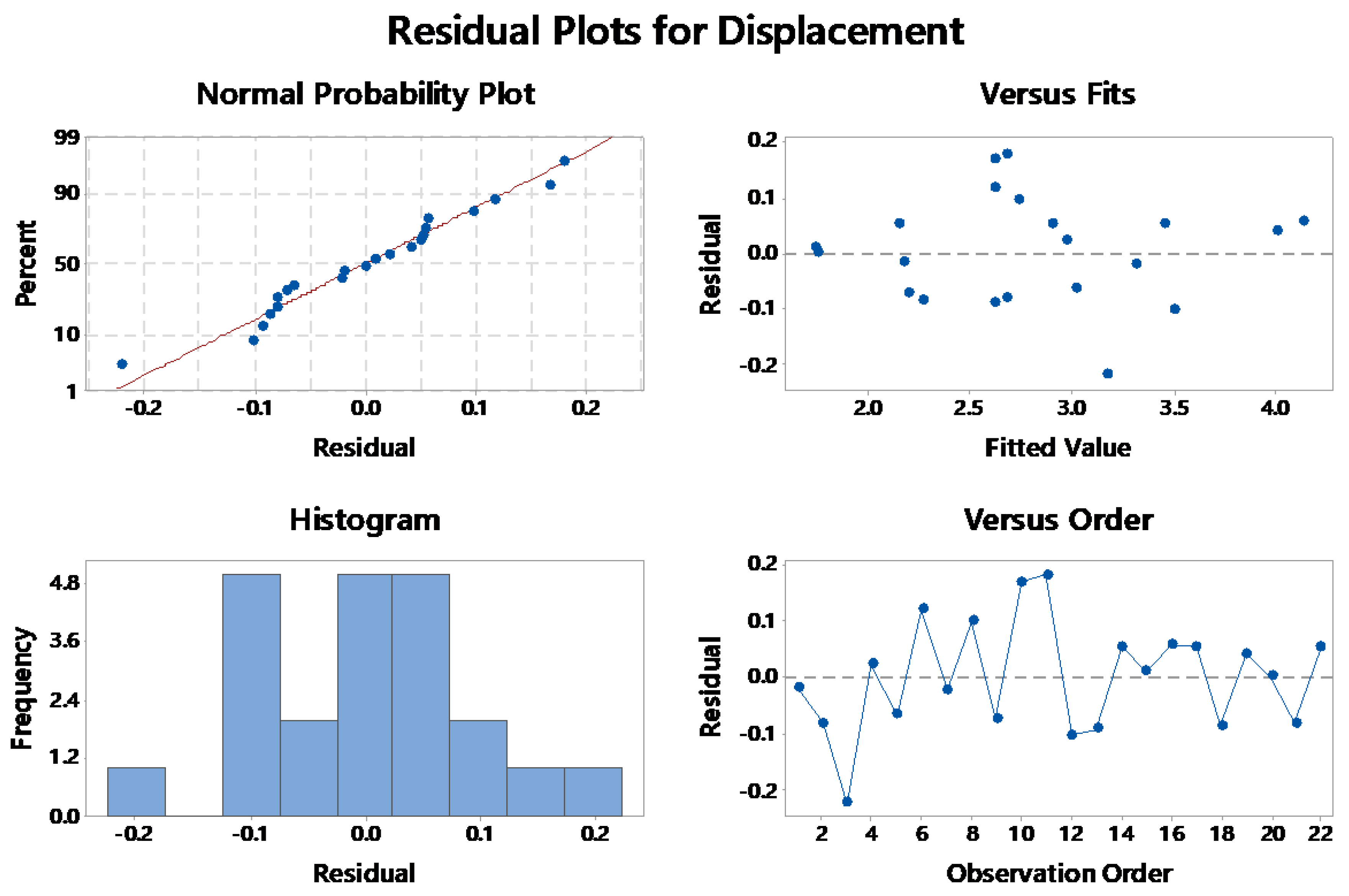
Figure 3.
Plots of main effects on the displacement of sample point H.

Figure 4.
The interaction of spiral pitch and the number of spiral passes on the displacement of sample point H.
Figure 4.
The interaction of spiral pitch and the number of spiral passes on the displacement of sample point H.
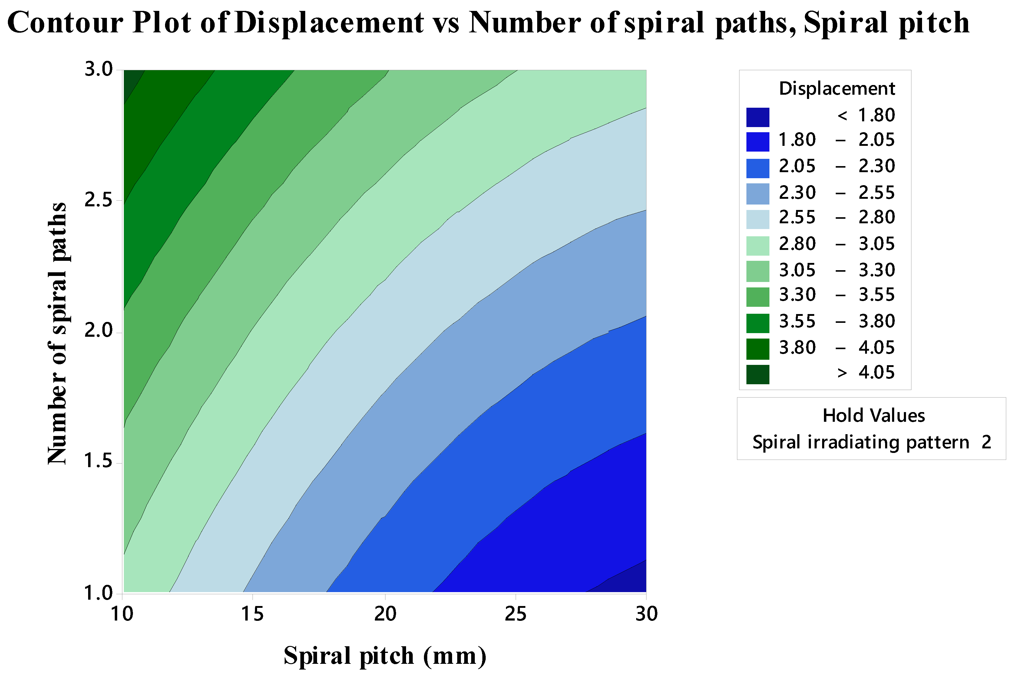
Figure 5.
Parameter optimization to obtain the maximum value of displacement of sample point H.

Table 1.
Comparison of the irradiation schemes for the laser formation of curved sheets.
| Reference | Fabricated Shape | Irradiation Scheme | Material | Laser Power (Watts) | Blank Dimensions |
|---|---|---|---|---|---|
| Chakraborty et al. [9] | Bowl-shaped surface | Radial scan | AISI 304 stainless steel | 350 | ϕ100 mm, 1 mm thickness |
| Liu and Yao [10] | Pillow- and saddle-shaped surfaces | Calculated paths | 1010 mild steel | 1000 | 140 × 80 × 0.89 mm3 |
| Na and Kim [11] and Kim and Na [12] | Saddle-shaped surface | Calculated paths | mild steel | 100 | 30 × 30 × 0.8 mm3 |
| Gao et al. [13] | Ship hull shape | Calculated paths | S275 steel | 400 | 100 × 100 × 1.5 mm3 |
| Imani Shahabad et al. [14,15] | Dome-shaped surface | Spider scanning paths | AA 6061-T6 aluminium alloy | 2500 | ϕ150 mm, 2 mm thickness |
| Shen et al. [16,17] | Pillow, warped and saddle shape | Computational scanning path | 304 stainless steel | 200 | 100 × 100 × 2 mm3 100 × 100 × 1 mm3 |
| Maji et al. [21] | Dome-shaped surface | Cross (axial and diagonal) scanning paths | AISI 304 stainless steel | 400 | 60 × 60 × 1 mm3 90 × 90 × 1 mm3 120 × 120 × 1 mm3 |
Table 2.
Chemical composition of a mild steel sheet.
| Component | Fe | C | Cu | Cr | Ni | Mn | Si | P | S |
|---|---|---|---|---|---|---|---|---|---|
| Weight (%) | Base | 0.194 | 0.261 | 0.103 | 0.155 | 0.673 | 0.183 | 0.046 | 0.057 |
Table 3.
The experimental test plan designed according to Response Surface Method (including the results).
Table 3.
The experimental test plan designed according to Response Surface Method (including the results).
| Sample | Spiral Pitch (mm) | Number of Spiral Passes | Spiral Pattern | Deformation of Sample Point H (mm) |
|---|---|---|---|---|
| 1 | 20 | 1 | 1 | 2.16 |
| 2 | 20 | 2 | 2 | 2.60 |
| 3 | 20 | 3 | 1 | 2.95 |
| 4 | 10 | 1 | 2 | 3.00 |
| 5 | 10 | 1 | 1 | 2.95 |
| 6 | 20 | 2 | 1 | 2.74 |
| 7 | 20 | 3 | 2 | 3.29 |
| 8 | 30 | 3 | 1 | 2.84 |
| 9 | 30 | 2 | 1 | 2.12 |
| 10 | 20 | 2 | 1 | 2.79 |
| 11 | 20 | 2 | 2 | 2.86 |
| 12 | 10 | 2 | 2 | 3.40 |
| 13 | 20 | 2 | 1 | 2.53 |
| 14 | 30 | 3 | 2 | 2.95 |
| 15 | 30 | 1 | 2 | 1.75 |
| 16 | 10 | 3 | 2 | 4.19 |
| 17 | 20 | 1 | 2 | 2.21 |
| 18 | 30 | 2 | 2 | 2.18 |
| 19 | 10 | 3 | 1 | 4.05 |
| 20 | 30 | 1 | 1 | 1.75 |
| 21 | 20 | 2 | 2 | 2.60 |
| 22 | 10 | 2 | 1 | 3.51 |
Table 4.
The levels of laser formation process parameters.
| Parameter | Symbol | Levels | |||
|---|---|---|---|---|---|
| Spiral pitch (mm) | S | 10 | 20 | 30 | |
| Number of spiral passes | N | 1 | 2 | 3 | |
| Spiral pattern | P | In-to-out (1) | Out-to-in (2) | ||
Table 5.
ANOVA results for displacements of sample point H in laser-formed saddle-shaped surfaces.
| Term | Coef. | SE Coef. | T-Value | P-Value |
|---|---|---|---|---|
| Constant | 2.6516 | 0.0446 | 59.44 | 0.000 |
| S | −0.6258 | 0.0355 | −17.63 | 0.000 |
| N | 0.5375 | 0.0355 | 15.14 | 0.000 |
| P | −0.0291 | 0.0262 | −1.11 | 0.287 |
| S × S | 0.2036 | 0.0546 | 3.73 | 0.003 |
| N × N | 0.0536 | 0.0546 | 0.98 | 0.345 |
| S × N | 0.0024 | 0.0435 | −0.03 | 0.643 |
| S × P | −0.0075 | 0.0355 | −0.21 | 0.836 |
| N × P | −0.0408 | 0.0355 | −1.15 | 0.271 |
Table 6.
ANOVA test result summary for checking the adequacy of the proposed model.
| Source | DF | Adj SS | Adj MS | F-Value | P-Value | Significance |
|---|---|---|---|---|---|---|
| Regression | 8 | 8.47954 | 1.05994 | 70.09 | 0.000 | OK |
| Linear | 3 | 8.18550 | 2.72850 | 180.43 | 0.000 | OK |
| Square | 2 | 0.27336 | 0.13668 | 9.04 | 0.003 | OK |
| Interaction | 3 | 0.02068 | 0.00689 | 0.46 | 0.718 | Not-OK |
| R2 = 97.73% | ||||||
| Pred R2 = 94.33% | ||||||
| Adj R2 = 96.34% |
© 2020 by the authors. Licensee MDPI, Basel, Switzerland. This article is an open access article distributed under the terms and conditions of the Creative Commons Attribution (CC BY) license (http://creativecommons.org/licenses/by/4.0/).
Share and Cite
MDPI and ACS Style
Safari, M.; Alves de Sousa, R.; Joudaki, J. Fabrication of Saddle-Shaped Surfaces by a Laser Forming Process: An Experimental and Statistical Investigation. Metals 2020, 10, 883. https://doi.org/10.3390/met10070883
AMA Style
Safari M, Alves de Sousa R, Joudaki J. Fabrication of Saddle-Shaped Surfaces by a Laser Forming Process: An Experimental and Statistical Investigation. Metals. 2020; 10(7):883. https://doi.org/10.3390/met10070883
Chicago/Turabian StyleSafari, Mehdi, Ricardo Alves de Sousa, and Jalal Joudaki. 2020. "Fabrication of Saddle-Shaped Surfaces by a Laser Forming Process: An Experimental and Statistical Investigation" Metals 10, no. 7: 883. https://doi.org/10.3390/met10070883
Note that from the first issue of 2016, this journal uses article numbers instead of page numbers. See further details here.