Process Development for a Superplastic Hot Tube Gas Forming Process of Titanium (Ti-3Al-2.5V) Hollow Profiles


Fraunhofer Institute for Machine Tools and Forming Technology IWU, 09126 Chemnitz, Germany
*
Author to whom correspondence should be addressed.
Metals 2020, 10(9), 1150; https://doi.org/10.3390/met10091150
Submission received: 13 July 2020
/
Revised: 12 August 2020
/
Accepted: 21 August 2020
/
Published: 25 August 2020
(This article belongs to the Special Issue Superplasticity and Superplastic Forming)
Abstract
:Tube forming technologies based on internal forming pressures, such as hydroforming or hot tube gas forming, are state of the art to manufacture complex closed profile geometries. However, materials with excellent specific strengths and chemical properties, such as titanium alloys, are often challenging to shape due to their limited formability. In this study, the titanium alloy Ti-3Al-2.5V was processed by superplastic hot tube gas forming to manufacture a helically shaped flex tube. The forming process was investigated in terms of process simulation, forming tool technology and process window for the manufacturing of good parts. Within a simulation study, a strain rate optimized forming pressure–time curve was defined. With the newly developed tool design, forming temperatures up to 900 °C and internal forming pressures up to 7 MPa were tested. A process window to manufacture good parts without necking or wrinkling has been successfully identified. The experiment data showed good agreement with the numerical simulations. The detailed study of the process contributes to an in-depth understanding of the superplastic forming of Ti-3Al-2.5V during hot tube gas forming. Furthermore, the study shows the high potential of superplastic hot tube gas forming of titanium alloys for the manufacturing of helical flex tubes and bellows.
1. Introduction
Titanium and its alloys have become a popular construction material in recent decades due to their high specific strength, excellent corrosion behavior and good mechanical properties [1]. The extraordinary property profile of this material makes it particularly interesting for applications in the fields of aerospace, medical technology, chemical process engineering or marine and offshore technology [2]. Besides machining, forging as well as sheet metal and profile forming are the most important manufacturing processes [3]. Due to the low ductility as well as the high yield stress of titanium and its alloys, the forming capacity at room temperature is limited. Therefore, complex component geometries also require adapted forming processes. These limitations can be overcome by means of temperature-supported forming processes and by taking advantage of microstructural and chemical properties.
In recent years, the increasing demand for tubular and profile components made of titanium alloys has become apparent in the fields of aerospace propulsion technology and chemical process engineering. Flex tubes and bellows in particular are examples of applications. Flex tubes made of titanium alloys are used for various reasons, among which the resistance to corrosive media, even at elevated operating temperatures, is the most important one. The corrugated structure ensures resistance to cyclic loads, one of the main reasons for the use of flexible tubes and bellows. As described by Lee et al. [4], conventional flexible tubes and bellows are manufactured by a multi-stage forming process. For this purpose, tubes or hollow profiles are bulged in a hydroforming process and the resulting convolutions are folded in a subsequent compression process [4]. In the past few years, several investigations have been carried out on the production of bellows. Faraji et al. [5] as well as Bakhshi-Jooybari et al. [6] dealt with the numerical design of the manufacturing processes, focusing on the pressure path during the process. Liu et al. [7] developed multi-layer bellows, investigated their manufacturing and the resulting springback behavior. Another emerging trend is the die-less manufacturing of bellows, which was investigated by Sedighi et al. [8] and Zhang et al. [9]. An alternative to conventional u-shaped bellows are s-shaped bellows. The production of reinforced s-shaped bellows was the subject of the study by Yuan et al. [10]. Most studies investigated the production of bellows and flex tubes made of steel and aluminum alloys. However, there is a lack of publications dealing with the complex and challenging manufacturing of titanium bellows and flex tubes, e.g., Wang et al. [11].
Common to all mentioned publications is that flex tubes and bellows have so far been limited to rotationally symmetrical geometries, regardless of the material used. For use as fuel or hydraulic pipes in propulsion systems and as pipelines in the chemical industry, however, the problem arises that the liquid or gaseous media do not flow through the pipes in a flow-optimized way and that turbulences occur. This also results in an increased cleaning effort of the pipes. A helical flex tube or bellow geometries with helical convolutions can improve the flow significantly.
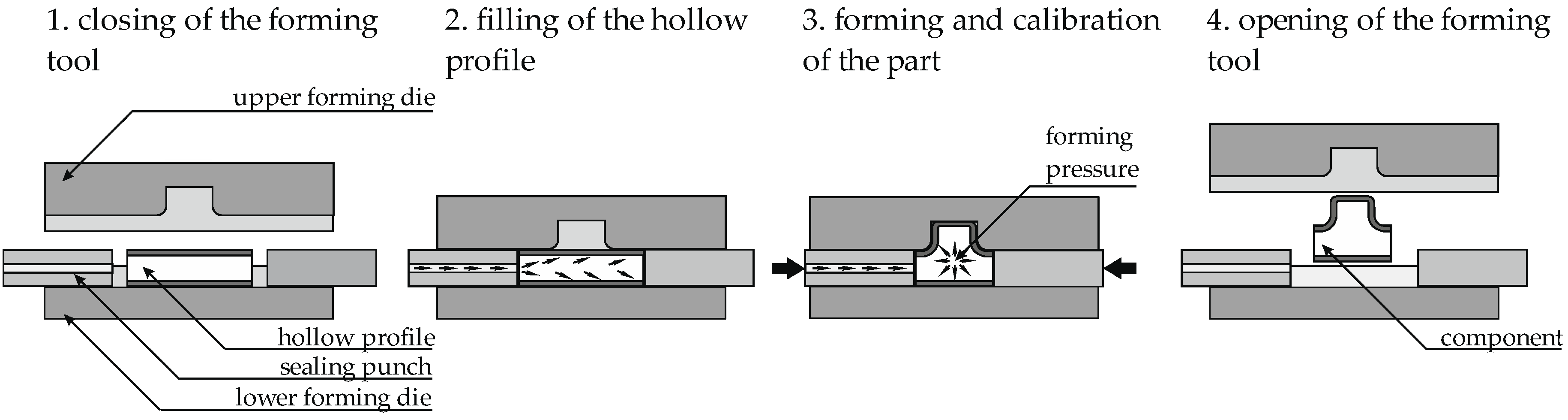
Titanium alloys are difficult to form due to their microstructure (hexagonal crystal structure of the α-phase) and the resulting mechanical properties, such as high tensile strength and low Young’s modulus. Odenberger [12] explained how these material disadvantages can be overcome by thermomechanical forming processes. The possibility of superplastic forming (SPF) of titanium and its alloys has been known for decades [2]. SPF means forming at very low strain rates far above the recrystallization temperature in order to form the material and simultaneously use its effects of dynamic recrystallization, which allows elongations of several hundred percent [13,14]. The requirement for this is an equiaxed fine grain microstructure [15]. Despite the fact that the effects of superplasticity are very well known, most superplastic forming processes for titanium alloys have so far been limited to sheet metal forming. This publication presents a concept to combine conventional hot tube gas forming processes with the superplastic forming of titanium alloys. Hot tube gas forming describes the forming of heated tubes or hollow profiles with a forming pressure inside the profile bodies applied by a gaseous instead of a fluid forming medium. Figure 1 shows the principle of hot tube gas forming. Thereby, the tubes or profiles are formed into the die cavity by an inner forming pressure [16,17]. Whereas fluid-based forming media are preferably used in hydroforming, the use of gaseous forming media is essential in hot tube gas forming and similar high-temperature applications.
Figure 2 shows the intended demonstrator geometry, which is a complex helically shaped flex tube. Manufacturing the challenging component geometry from Ti-3Al-2.5V requires the utilization of the superplastic material behavior of fine-grained titanium alloys at high temperatures and very low strain rates. Due to the component geometry, it is also clear that axial feeding is not possible. The geometry with several convolutions blocks a homogeneous material flow into all areas of the component through axial feeding.
Hot tube gas forming as a further development of conventional hydroforming has been state of the art for several years. During the last few years, one important research focus has been put on press hardening of semi-finished tube products made of boron-manganese steels [17] and the process combination of hot tube gas forming and injection molding [18]. One of the technological issues in conventional hot tube gas forming is the heating concept. In addition to the more conventional furnace heating of tubes and profiles, more innovative techniques such as inductive component or tool heating [19] or conductive component heating [20] have also been considered. These concepts focus on rapid heating and fast forming processes with less complex pressure–time curves. Temperature management during longer process times and the control of sensitive pressure–time curves are challenges in hot tube gas forming.
However, for simpler component geometries, hot tube gas forming of titanium alloys is also state of the art. Zheng et al. [21] recently summarized the development of the more general hot medium pressure forming in detail. In addition to the term hot tube gas forming, the terms hot metal gas forming [22], high pressure pneumatic forming [23,24], hot gas forming [19,25] or high pressure tube gas forming [19] have also been used in recent years for the high-temperature forming of tube components with inner forming pressure. Liu et al. investigated in [26] approaches to improve the wall thickness distribution in hot tube gas forming of TA15 and in [24] the determination of the formability of titanium tubes at elevated temperatures. Liu et al. combined these results in [19,23] and investigated the forming of titanium tube demonstrator components in [27]. Wu et al. [28] showed an adaptation of hot gas forming for tube components by heating the components only in segmented areas, thus enabling axial feeding. Wang et al. discussed in [29] and [30] the effects of dynamic recrystallization on hot deformation mechanisms during hot gas forming of titanium tubes. Lee et al. [31] showed an approach to the combination between hot tube gas forming and superplastic forming of Ti-3Al-2.5V for profile geometries.
2. Objective
The combination of hot tube gas forming with superplastic forming requires a suitable tool concept that fulfills the specifications in terms of forming temperature, accurate pressure build-up to ensure predefined strain rates and maximum forming pressure. In conventional hot tube gas forming, either the tubes and hollow profiles or the forming tools are heated to reach the necessary forming temperatures. These forming processes last only a few seconds [22], which allows the use of different heating concepts, such as induction heating, without any problems. SPF processes, however, take up to several minutes, which means that the forming temperature must be kept constant over a much longer period of time. As a result, conductive [20] as well as inductive strategies for component heating are no longer suitable. Therefore, a method for component heating, either directly or via tool heating, has to be developed. It has to be capable of reaching forming temperatures of up to 900 °C and of setting a homogeneous temperature profile across the tool surface and component geometry. This is very important because the microstructure and consequently the mechanical properties of titanium alloys are significantly influenced by temperature and the degree of deformation [32]. Besides that, it is well known that titanium alloys are strain rate-sensitive in forming processes [33,34]. Especially in the case of superplastic forming, it is important that a critical strain rate is not exceeded in order to avoid necking and cracking in the process. At the same time, the maximum strain rate should not be too low to ensure an acceptable process time. This manuscript presents an approach in developing a superplastic hot tube gas forming process with the help of numerical simulations. The simulation results provide the first data for experimental tests investigating the manufacturing of complex helically shaped flex tubes.
3. Process Design and Simulation
The SPF process design is based on simulation studies using the simulation software LS-DYNA. The tool active parts were implemented as rigid active surfaces in the form of shell meshes and an elastically and plastically deformable tube (modelled as volume elements with initial element length of 0.136 mm, which equals three elements over tube wall thickness) was expanded in the cavity under an internal forming pressure. According to the investigations of Paul et al. [35] regarding hot tube gas forming processes, a static friction coefficient of µS = 0.35 was assumed initially between the active surfaces and the tube for first simulation studies. The heating of the tube was not considered within the simulation. Instead, an ideally isothermal state at a process temperature of 900 °C was assumed.
Since the use of seamless drawn tubes with an outer diameter of 6.4 mm and a wall thickness of 0.41 mm was intended, the semi-finished product was considered as a homogeneous continuum in the simulation model. Based on the literature data of Salam et al. [15,36], an elastic-plastic material model, which is common for hydroforming and hot tube gas forming processes, for an isothermal forming process of Ti-3Al-2.5V for the target temperature of 900 °C was derived. To model the elastic-plastic material behavior for Ti-3Al-2.5V, an isothermal material model was derived for the target temperature of 900 °C based on existing literature data. The reason for this is that it is not possible to determine the material properties of this small tube material experimentally using standardized test processes such as hot tensile tests, for example. Extended test procedures, such as hot tube bulge tests or hot tensile tests on the entire tube cross section, could provide a more precise data basis for the material behavior in the future, but were not pursued in the context of the present work. Due to the necessary assumption of a material flow behavior based on the existing literature, the simulation results are to be questioned critically and can only provide a first indication of the properties of the forming process and possible process limits.
Within the modeling of the flow properties of the material, the consideration of the strain rate dependency of the flow stresses is crucial to represent superplastic forming conditions. Based on the investigations of Salam et al. [15,36], the initial flow stresses for Ti-3Al-2.5V at different strain rates for 880 and 910 °C in a strain rate range of 8 × 10⁻⁵ s−1 to 3 × 10⁻³ s−1 were extrapolated up to 1 × 10⁻⁵ s−1 and 1 × 10⁻² s−1, to provide a wider range of strain rates within the material model. Subsequently, linear interpolation between 880 and 910 °C to the 900 °C target temperature was performed along discrete interpolation points. Figure 3 shows the increase in the initial yield stress with an increasing strain rate in the considered strain rate range. Consequently, the strain rate sensitivity index m increases up to 8 × 10⁻⁴ s−1 and decreases with higher strain rates. This determines the strain rate range for superplastic forming.
On the basis of the investigations of Nazzal et al. [37] and Kim et al. [38] on the strain rate behavior of Ti-6Al-4V, it can be assumed, that from a strain rate of 1 × 10⁻² s−1 onwards, the strain rate sensitivity index m will decrease further, which is equivalent to only a slight increase in the yield stress as the strain rate increases. Forming in these higher strain rate ranges leads to early material localization or necking and thus to component failure. For this reason, the pressure–time curve for the respective forming process has to be adjusted in such way that a critical strain rate level is not exceeded in order to ensure superplastic behavior. Therefore, according to the summarized results in Figure 3, a value of 2 × 10⁻³ s−1 is initially assumed as the maximum allowable strain rate. This makes sure that the occurring strain rates are safely in the SPF process window and at the same time, it ensures acceptable process times. The derived strain rate sensitivity of the initial yield stress from Figure 3 was stored in the material model in tabular form using discrete flow curve datasets. In addition, the dependence of the yield stress on the degree of forming was determined according to the results of Alabort et al. [39], who investigated the change in flow stress with an increasing degree of forming for the titanium alloy for Ti-6Al-4V. However, based on the existing literature data, it can be expected that the flow curve shows only very little hardening potential at a temperature of 900 °C.
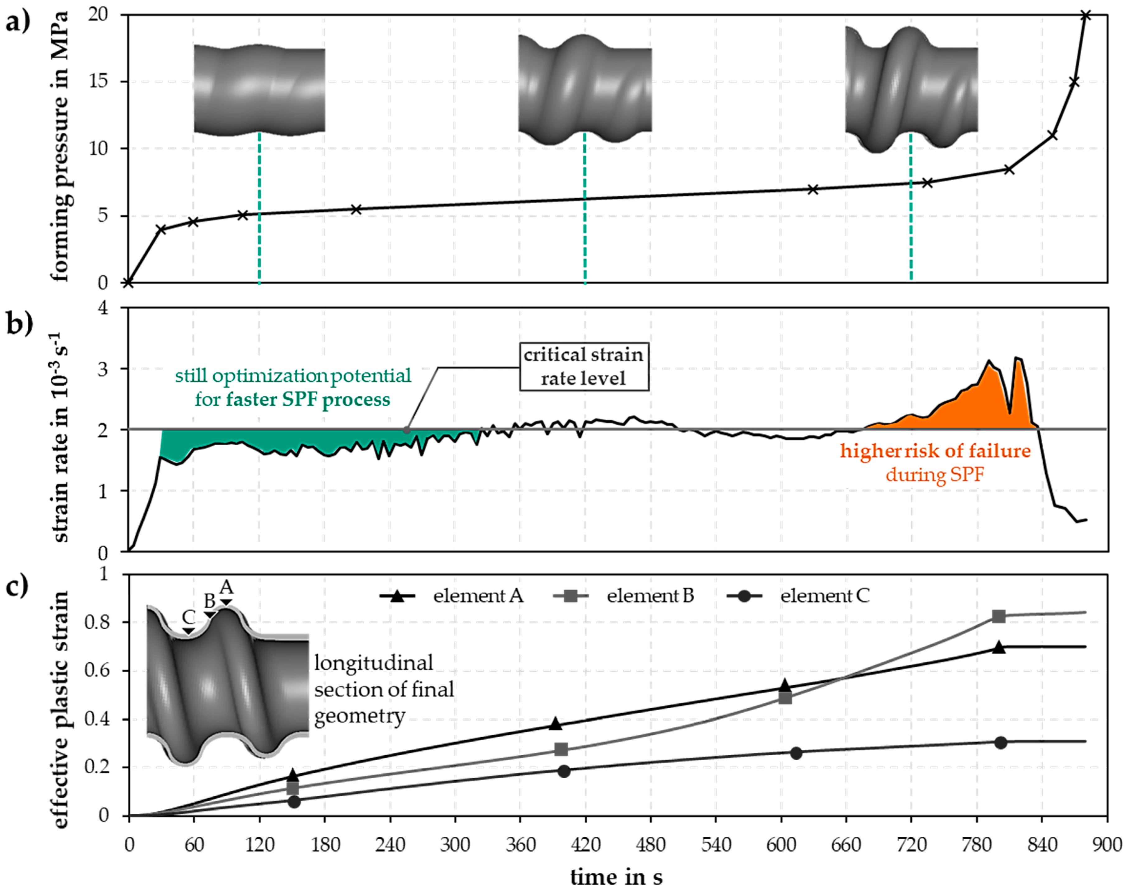
Figure 4 summarizes the results of the final simulation of the optimized time-dependent forming pressure curve, which ensured an adherence of the set maximum strain rate. Figure 4a shows the developed time-dependent forming pressure curve and several forming stages over time. Figure 4b illustrates the resulting maximum strain rate over time of the whole part together with the defined strain rate limit. Figure 4c summarizes the development of the effective plastic strain of three exemplary elements in critical forming areas. Within several simulation studies, the pressure curve was adjusted manually in several iterations until the maximum strain rate level over time approached the specified strain rate maximum of 2 × 10⁻³ s−1. Figure 4a shows the developed forming process in which an internal pressure of up to 20 MPa is set over 880 s. It becomes clear that at the beginning of the forming process, a fast pressure build-up is tolerable to overcome the yield point first. In fact, Figure 4b shows that it is evident that there is still optimization potential for the first 300 s of the process, since the maximum strain rate level is below the specified strain rate limit. Therefore, the process could run faster in this section by setting a steeper internal pressure-time curve. However, as an initial solution for feasibility studies, this internal pressure–time curve has been evaluated as sufficient.
In the time window between 300 and 690 s, the internal pressure increases linearly from 5.8 to about 7.3 MPa, leading to slight deviations from the defined critical strain rate. From 690 s onwards, the internal pressure and strain rate increase significantly again. The strain rate in some cases is well above the set maximum strain rate of 2 × 10⁻³ s−1. However, based on the results shown in Figure 4c and in consideration that the defined strain rate limit is within a certain safety range, this was evaluated as still not critical. In Figure 4c, an examination of the strain curve over time of three exemplary elements in critical forming areas of the component also demonstrates that the majority of the forming process has already taken place after about 800 s and at an internal pressure of 8.3 MPa. A further pressure build-up serves to calibrate the component. Component failure due to a too high strain rate can be excluded from this point on. Element A in the outer convolution shows a steady growth of the effective plastic strain over time since the forming process is characterized by free forming in this area. Element B in the transition area shows a flat increase in the effective plastic strain until about 450 s. From this moment on, the curve rises steeply due to the decreasing free arc length available for forming. The material flow is based on this free arc length only. Element C represents the least critical forming areas with the lowest effective plastic strain. Figure 4c also illustrates the two process phases characteristic for hot tube gas forming processes, forming and calibrating. Up to about 800 s and an internal pressure of about 8.3 MPa, most of the component forming takes place. From this point on, the geometry is only calibrated, and a significant deformation of the component is no longer detectable. This means that, according to the numerical results, a forming pressure above 8 MPa is not necessary for manufacturing the part.
In order to obtain deeper understanding of the forming history of the part, Figure 5 illustrates representative deformation states over time. It becomes clear how the material slowly aligns to the die contour over the process time, with the outer convolution being the last region to be formed. Due to the earlier contact of the material at the transition areas, maximum thinning occurs in these regions, too. After 850 s and an internal pressure of 11 MPa, the process simulation is finished and the component is fully calibrated. In the area of the outer convolution, the wall thickness is reduced to 0.214 mm, which corresponds to a wall thinning of 48%. The adjustment of a more homogeneous wall thickness profile is limited by the part geometry, since the early contact of the material with the tool contour reduces further material flow.
4. Tool Concept
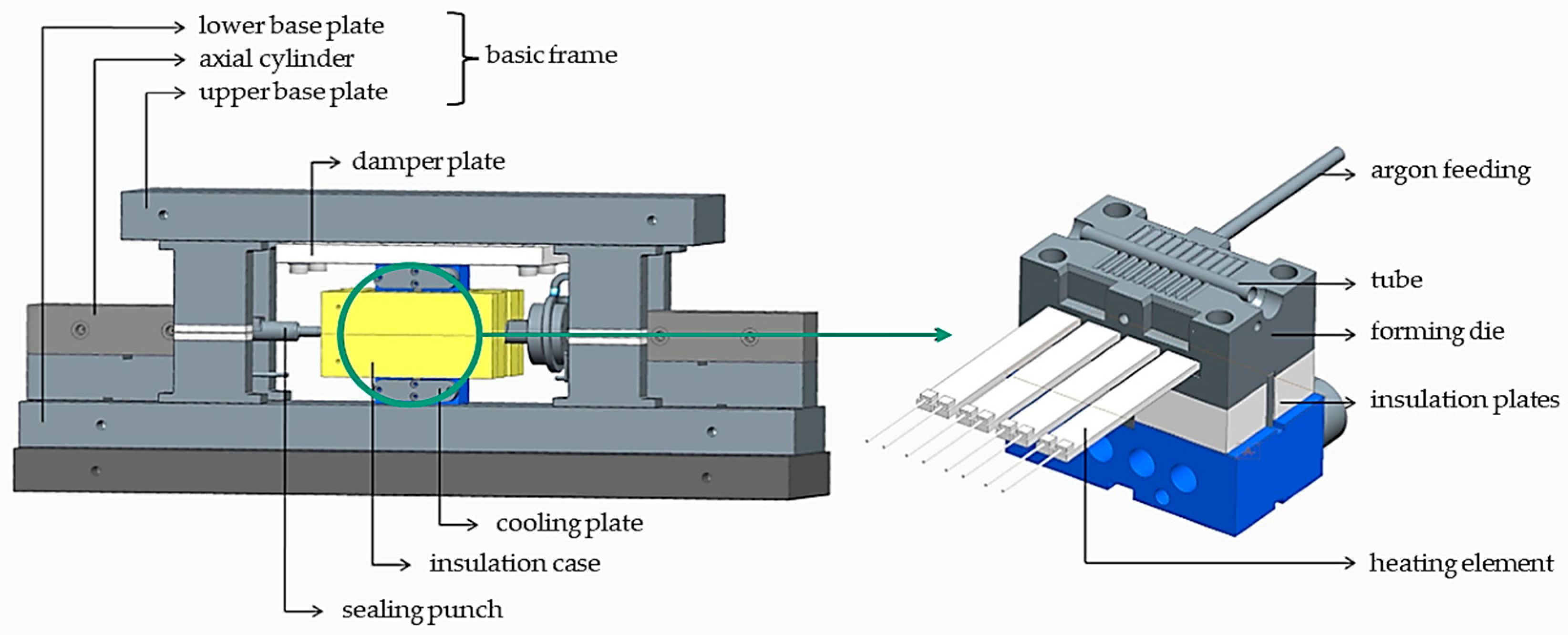
Figure 6 shows the developed forming tool. The strain rate-optimized forming process and the process parameters derived from it served as a basis for the design of the forming tool.
It has to be possible to set a constant forming temperature of over 900 °C, which has to be homogeneous over the tool surface. In addition, forming pressures of up to 15 MPa and very slow pressure build-up rates are indispensable. Due to the atmospheric sensitivity of titanium and its alloys, argon gas was used as a forming medium. Four heating elements are integrated in each of the high-temperature-resistant active parts of the forming tool, which can heat the tool up to 950 °C. The die is insulated and thermally decoupled both from the outside and in the closing direction of the press. The axial sealing punches seal the tube and induce the argon gas. The pressure intensifier unit can be used to set a maximum internal pressure of 15 MPa with a control accuracy of 0.01 to 2 MPa and 0.05 from 2 MPa. A supply tract for argon feeding is also integrated in the lower part of the tool to reduce the oxygen content in the closed and sealed tool. The argon gas flows directly into the tool cavity.
5. Results
Figure 7 shows the comparison of the numerically determined process diagram and the actual process. The semi-finished tube products are inserted at room temperature into the tool, which has already been heated to the temperature of 905 °C. The temperature of the tool is recorded with an integrated sensor near the tool surface. Separate temperature measurements on the surface confirmed the target temperature of 900 °C. After the closing of the tool, a defined homogenization and recrystallization time of 600 s begins in order to bring both the tool and component temperature to the forming temperature and to recrystallize the material that has been hardened during the production of the tubes. After 600 s, the actual superplastic hot tube gas forming process begins. The initial tests with the simulated pressure–time curve showed that the pipes burst if the internal pressure exceeds 6.7 MPa. Hence, the pressure–time curve was adjusted, as shown in Figure 7. During the first 100 s, the pressure–time curve is exactly the same as in the simulation. However, instead of a further linear increase in the internal pressure after about 200 s after the recrystallization, as assumed in the simulation, the pressure curve turns into a plateau-like curve at a constant internal pressure of 6.7 MPa. This modification of the pressure–time curve prevents early bursting of the tubes. The slightly higher internal pressure between about 100 and 350 s was proved to be uncritical since the resulting strain rate of the simulated pressure curve has been significantly under the maximum strain rate at this stage of the process, as can be seen in Figure 4b. The temporally higher internal pressure in the experiments results in a marginally higher strain rate only. Furthermore, it became clear that the tubes are already completely formed after a total process time of 630 s, which is an indicator for a much faster forming process than originally simulated. This suggests that the actual strain rate during the process is significantly higher than expected. The application of the simulated pressure curve in the experiment leads to a much faster forming compared to the numerical prediction. Thus, the stress level of the material model in the simulation seems to be too high in comparison to the experimental behavior, so that a specific pressure level in the simulation leads to a slower forming in comparison to the experiment. A continuation of the process beyond the time of 630 s and beyond an internal pressure of 6.7 MPa was not performed.
Figure 8 shows that the forming process is much faster than numerically predicted. It compares the real part, which was exemplarily removed from the process after 180 s, with the results of the process simulation after 180 s. The real part is significantly more shaped than it is within the simulation.
Potential reasons for this deviation are diverse and can be divided into material and process related influences. For example, the strain rate-dependent material model used for the simulation is only an assumption, which can deviate from the actual material properties of pilgered tubes. It can be assumed that the yield stress level set in the material model is higher than in the actual material condition. Assuming the same forming pressures, lower actual yield stress results in an earlier starting forming process. Moreover, the forming process progresses faster than assumed. Furthermore, there are also some influencing variables in the die affecting the forming process. The set static friction coefficient of µS = 0.35 is an assumption which is also used for similar isothermal forming processes. However, the actual coefficient of friction can vary as the tubes are coated with boron nitride as a release agent before the process. Residues of the release agent as well as an uneven removal of the release agent from the component during the forming process can lead to inhomogeneous coefficients of friction depending on the respective forming stage. Furthermore, already small inaccuracies in the process parameters could lead to short-term strain peaks.
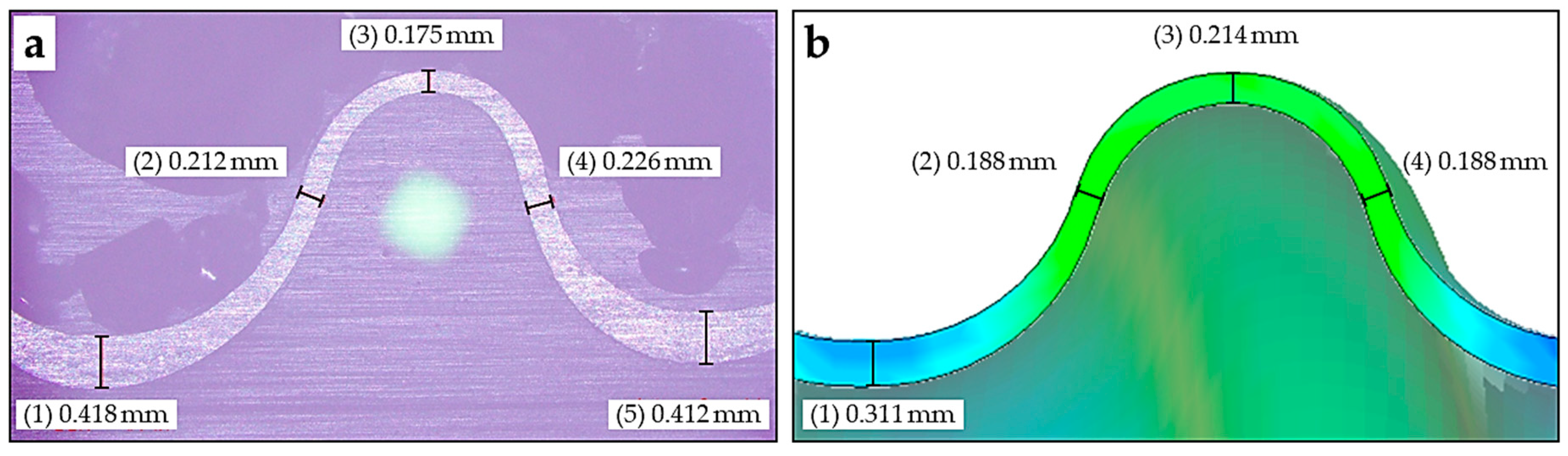
Figure 9 shows the extent to which the faster forming process affects the thinning of the wall in the final state of both experiment (a) and simulation (b). Here, the wall thickness distribution in a longitudinal section of a real component (a) is compared to the corresponding simulation result (b). The measuring points are located in the area of the inner convolution, the transition areas and in the area of the outer convolution. Considering the real component, it becomes clear that the wall thickness in the area of the inner convolution, where no forming takes place, is equal to the initial wall thickness, which shows that no material has flowed into the adjacent areas. In the simulation, however, a material flow into the adjacent transition areas leads to a reduction in the wall thickness in the inner convolution to about 0.3 mm. A comparison of the transition areas of the real component with 0.212 to 0.226 mm remaining wall thickness and the simulation shows that the simulation predicts a lower remaining thickness of 0.188 mm. This can be explained by the fact that the wall thickness in the transition areas decreases due to material flow into the area of the outer convolution. In the real component, it is clear that this material flow into the outer convolution is significantly lower, which can be due to strain rate effects or changed friction conditions.
6. Summary and Conclusions
The presented results demonstrate the feasibility of manufacturing helical flex tubes from Ti-3Al-2.5V by superplastic hot tube gas forming. The developed method as well as the developed die concept can also be transferred to other superplastically formable titanium alloys. Extensive simulation studies were carried out to derive a process window that ensured that the strain rates that occur when applying a forming pressure did not exceed a defined strain rate limit. This approach allows the exploitation of strain rate effects of the material. A comparison of the simulation results with the outcomes from the forming tests showed that the real process was faster than simulated. However, the numerical results show a sufficiently good agreement with the manufactured parts. One of the reasons for the deviating experimental results is the used material model for simulation, which does not reflect the exact material condition of the used semi-finished tube products. The determination of material properties for tubes and hollow profiles is a well-known problem in hot tube gas forming [40,41]. The characterization of the high-temperature material properties of thin-walled tubes with small diameters is one of the forthcoming main areas of research. In summary, this study shows the high potential of superplastic hot tube gas forming of titanium alloys for the manufacturing of helical flex tubes and bellows.
Author Contributions
Conceptualization, R.T. and S.W.; Data curation, R.T. and F.R.; Formal analysis, R.T. and F.R.; Investigation, R.T. and F.R.; Methodology, R.T. and F.R.; Project administration, R.T.; Software, F.R.; Supervision, V.P.; Validation, R.T.; Writing—original draft, R.T.; Writing—review & editing, R.T., F.R., S.W. and V.P. All authors have read and agreed to the published version of the manuscript.
Funding
This research received no external funding.
Conflicts of Interest
The authors declare no conflict of interest.
References
- Singh, P.; Pungotra, H.; Kalsi, N.S. On the characteristics of titanium alloys for the aircraft applications. Mater. Today Proc. 2017, 4, 8971–8982. [Google Scholar] [CrossRef]
- Titan und Titanlegierungen. Vortragstexte eines Fortbildungsseminars der Deutschen Gesellschaft für Materialkunde e.V. In Zusammenarbeit mit dem Institut für Werkstofforschung des GKSS-Forschungszentrum Geesthacht GmbH; Peters, M., Ed.; [3., völlig neu bearb. Aufl.], 3. Nachdr; Wiley-VCH: Weinheim, Germany, 2010; ISBN 978-3-527-30539-1. [Google Scholar]
- RMI Titanium Company. Titanium Alloy Guide. 2000. Available online: https://link.springer.com/content/pdf/10.1007/s00170-017-0642-1.pdf (accessed on 16 June 2020).
- Lee, S.W. Study on the forming parameters of the metal bellows. J. Mater. Process. Technol. 2002, 130, 47–53. [Google Scholar] [CrossRef]
- Faraji, G.; Mashhadi, M.M.; Norouzifard, V. Evaluation of effective parameters in metal bellows forming process. J. Mater. Process. Technol. 2009, 209, 3431–3437. [Google Scholar] [CrossRef]
- Bakhshi-Jooybari, M.; Elyasi, M.; Gorji, A. Numerical and experimental investigation of the effect of the pressure path on forming metallic bellows. Proc. Inst. Mech. Eng. Part B J. Eng. Manuf. 2009, 224, 95–101. [Google Scholar] [CrossRef]
- Liu, J.; Liu, Y.; Li, L.; Li, X. Springback behaviors of bi-layered non-homogeneous bellows in hydroforming. Int. J. Adv. Manuf. Technol. 2017, 93, 1605–1616. [Google Scholar] [CrossRef]
- Sedighi, M.; Shamsi, M. A new approach in producing metal bellows by local arc heating: A parametric study. Int. J. Adv. Manuf. Technol. 2017, 93, 3211–3219. [Google Scholar] [CrossRef]
- Zhang, Z.; Furushima, T.; Manabe, K.-I.; Tada, K.; Sasaki, O. Development of dieless metal bellows forming process with local heating technique. Proc. Inst. Mech. Eng. Part B J. Eng. Manuf. 2015, 229, 664–669. [Google Scholar] [CrossRef]
- Yuan, Z.; Huo, S.; Ren, J.; Han, J. Study on the hydroforming technology of reinforced s-shaped bellows. Int. J. Adv. Manuf. Technol. 2019, 103, 2541–2552. [Google Scholar] [CrossRef]
- Wang, G.; Zhang, K.F.; Wu, D.Z.; Wang, J.Z.; Yu, Y.D. Superplastic forming of bellows expansion joints made of titanium alloys. J. Mater. Process. Technol. 2006, 178, 24–28. [Google Scholar] [CrossRef]
- Odenberger, E.-L. Concepts for Hot Sheet Metal Forming of Titanium Alloys. Ph.D. Thesis, Luleå Tekniska Universitet, Luleå, Sweden, 2009. [Google Scholar]
- Sergueeva, A.V.; Stolyarov, V.V.; Valiev, R.Z.; Mukherjee, A.K. Superplastic behaviour of ultrafine-grained Ti–6A1–4V alloys. Mater. Sci. Eng. A 2002, 323, 318–325. [Google Scholar] [CrossRef]
- Yoshimura, H. Ultra-fine-grain refinement and superplasticity of titanium alloys obtained through protium treatment. Int. J. Hydrogen Energy 2002, 27, 769–774. [Google Scholar] [CrossRef]
- Salam, A.; Hammond, C. Superplasticity in Ti-3Al-2.5V. J. Mater. Sci. Lett. 2000, 19, 1731–1733. [Google Scholar] [CrossRef]
- Reimund, N. Hydro-Umformung; Springer: Berlin, Germany, 2007; ISBN 978-3-540-49013-5. [Google Scholar]
- Bach, M.; Degenkolb, L.; Reuther, F.; Psyk, V.; Demuth, R.; Werner, M. Conductive Heating during Press Hardening by Hot Metal Gas Forming for Curved Complex Part Geometries. Metals 2020, 10, 1104. [Google Scholar] [CrossRef]
- Drossel, W.-G.; Lies, C.; Albert, A.; Haase, R.; Müller, R.; Scholz, P. Process combinations for the manufacturing of metal-plastic hybrid parts. In IOP Conference Series: Materials Science and Engineering, Proceedings of the 18th Chemnitz Seminar on Materials Engineering—18. Werkstofftechnisches Kolloquium, Chemnitz, Germany, 10–11 March 2016; IOP Publishing: Bristol, UK, 2016; Volume 118, p. 12042. [Google Scholar] [CrossRef]
- Liu, G.; Wu, Y.; Wang, D.; Yuan, S. Effect of feeding length on deforming behavior of Ti-3Al-2.5 V tubular components prepared by tube gas forming at elevated temperature. Int. J. Adv. Manuf. Technol. 2015, 81, 1809–1816. [Google Scholar] [CrossRef]
- Bach, M.; Degenkolb, L.; Reuther, F.; Mauermann, R.; Werner, M. Parameter measurement and conductive heating during press hardening by hot metal gas forming. In IOP Conference Series: Materials Science and Engineering, Proceedings of the 38th International Deep Drawing Research Group Annual Conference (IDDRG 2019), Enschede, The Netherlands, 3–7 June 2019; IOP Publishing: Bristol, UK, 2019; pp. 3–7. [Google Scholar]
- Zheng, K.; Zheng, J.-H.; He, Z.; Liu, G.; Politis, D.J.; Wang, L. Fundamentals, processes and equipment for hot medium pressure forming of light material tubular components. Int. J. Lightweight Mater. Manuf. 2020, 3, 1–19. [Google Scholar] [CrossRef]
- Paul, A.; Werner, M.; Trân, R.; Landgrebe, D. Hot Metal Gas Forming of Titanium Grade 2 Bent Tubes; AIP Publishing: Melville, NY, USA, 2017; p. 050009. [Google Scholar]
- Liu, G.; Wang, J.; Dang, K.; Tang, Z. High Pressure Pneumatic Forming of Ti-3Al-2.5V Titanium Tubes in a Square Cross-Sectional Die. Materials 2014, 7, 5992–6009. [Google Scholar] [CrossRef]
- Liu, G.; Wu, Y.; Zhao, J.; Wang, K.; Yuan, S. Formability Determination of Titanium Alloy Tube for High Pressure Pneumatic Forming at Elevated Temperature. Procedia Eng. 2014, 81, 2243–2248. [Google Scholar] [CrossRef] [Green Version]
- Wu, Y.; Liu, G.; Wang, K.; Liu, Z.; Yuan, S. The deformation and microstructure of Ti-3Al-2.5V tubular component for non-uniform temperature hot gas forming. Int. J. Adv. Manuf. Technol. 2017, 88, 2143–2152. [Google Scholar] [CrossRef]
- Liu, G.; Wang, K.H.; Xu, Y.; Wang, B.; Yuan, S.J. An Approach to Improve Thickness Uniformity of TA15 Tubular Part Formed by Gas Bulging Process. AMR 2013, 712–715, 651–657. [Google Scholar] [CrossRef]
- Liu, G.; Wang, J.; Dang, K.; Yuan, S. The effect of pressurization path on high pressure gas forming of Ti-3Al-2.5V at elevated temperature. MATEC Web Conf. 2015, 21, 6007. [Google Scholar] [CrossRef]
- Wu, Y.; Liu, G.; Wang, K.; Liu, Z.; Yuan, S. Loading path and microstructure study of Ti-3Al-2.5V tubular components within hot gas forming at 800 °C. Int. J. Adv. Manuf. Technol. 2016, 87, 1823–1833. [Google Scholar] [CrossRef]
- Wang, K.; Liu, G.; Huang, K.; Politis, D.J.; Wang, L. Effect of recrystallization on hot deformation mechanism of TA15 titanium alloy under uniaxial tension and biaxial gas bulging conditions. Mater. Sci. Eng. A 2017, 708, 149–158. [Google Scholar] [CrossRef]
- Wang, K.; Liu, G.; Zhao, J.; Huang, K.; Wang, L. Experimental and modelling study of an approach to enhance gas bulging formability of TA15 titanium alloy tube based on dynamic recrystallization. J. Mater. Process. Technol. 2018, 259, 387–396. [Google Scholar] [CrossRef]
- Lee, Y.; Lim, J.; Yoon, E.; Song, Y.; Kwon, Y.; Moon, Y. Tube bulge forming for one-piece fabrication of multi-joint head tubes for Ti-alloy-body bicycles. Proc. Inst. Mech. Eng. Part B J. Eng. Manuf. 2015, 229, 639–646. [Google Scholar] [CrossRef]
- Winter, S.; Wagner, M.F.-X. On the effect of incremental forming on alpha phase precipitation and mechanical behavior of beta-Ti-10V-2Fe-3Al. IOP Conf. Ser. Mater. Sci. Eng. 2016, 118, 12026. [Google Scholar] [CrossRef] [Green Version]
- Winter, S.; Pfeiffer, S.; Bergelt, T.; Wagner, M.F.-X. Finite element simulations on the relation of microstructural characteristics and the formation of different types of adiabatic shear bands in a β-titanium alloy. IOP Conf. Ser. Mater. Sci. Eng. 2019, 480, 12022. [Google Scholar] [CrossRef]
- Tan, K.; Li, J.; Guan, Z.; Yang, J.; Shu, J. The identification of dynamic recrystallization and constitutive modeling during hot deformation of Ti55511 titanium alloy. Mater. Des. 2015, 84, 204–211. [Google Scholar] [CrossRef]
- Paul, A.; Reuther, F.; Neumann, S.; Albert, A.; Landgrebe, D. Process simulation and experimental validation of Hot Metal Gas Forming with new press hardening steels. J. Phys. Conf. Ser. 2017, 896, 12051. [Google Scholar] [CrossRef] [Green Version]
- Salam, A. Flow Stress-Strain Rate Behavior of Ti-3Al-2.5V Alloy at Low Temperatures in the Superplastic Range. J. Mater. Eng. Perform. 2012, 21, 253–256. [Google Scholar] [CrossRef]
- Nazzal, M.A.; Khraisheh, M.K.; Abu-Farha, F.K. The effect of strain rate sensitivity evolution on deformation stability during superplastic forming. J. Mater. Process. Technol. 2007, 191, 189–192. [Google Scholar] [CrossRef]
- Kim, T.W.; Dunne, F.P.E. Determination of superplastic constitutive equations and strain rate sensitivities for aerospace alloys. Proc. Inst. Mech. Eng. Part G J. Aerosp. Eng. 1997, 211, 367–380. [Google Scholar] [CrossRef]
- Alabort, E.; Putman, D.; Reed, R.C. Superplasticity in Ti–6Al–4V: Characterisation, modelling and applications. Acta Mater. 2015, 95, 428–442. [Google Scholar] [CrossRef] [Green Version]
- El-Morsy, A.; Akkus, N.; Manabe, K.; Nishimura, H. Evaluation of superplastic characteristics of tubular materials by multi-tube bulge test. Mater. Lett. 2006, 60, 559–564. [Google Scholar] [CrossRef]
- Reuther, F.; Mosel, A.; Freytag, P.; Lambarri, J.; Degenkolb, L.; Werner, M.; Winter, S. Numerical and experimental investigations for hot metal gas forming of stainless steel X2CrTiNb18. Procedia Manuf. 2019, 27, 112–117. [Google Scholar] [CrossRef]
Figure 1.
Schematic visualization of principle of hot tube gas forming.

Figure 2.
Design of helically shaped demonstrator part.
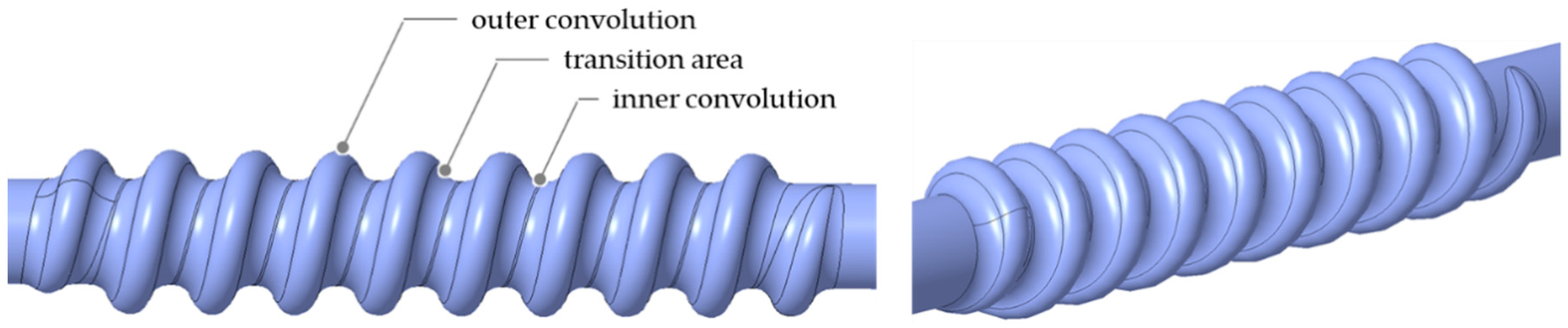
Figure 3.
Flow stress-strain rate diagram for Ti-3Al-2.5V according to [15,36] and derived values for the 900 °C forming temperature.
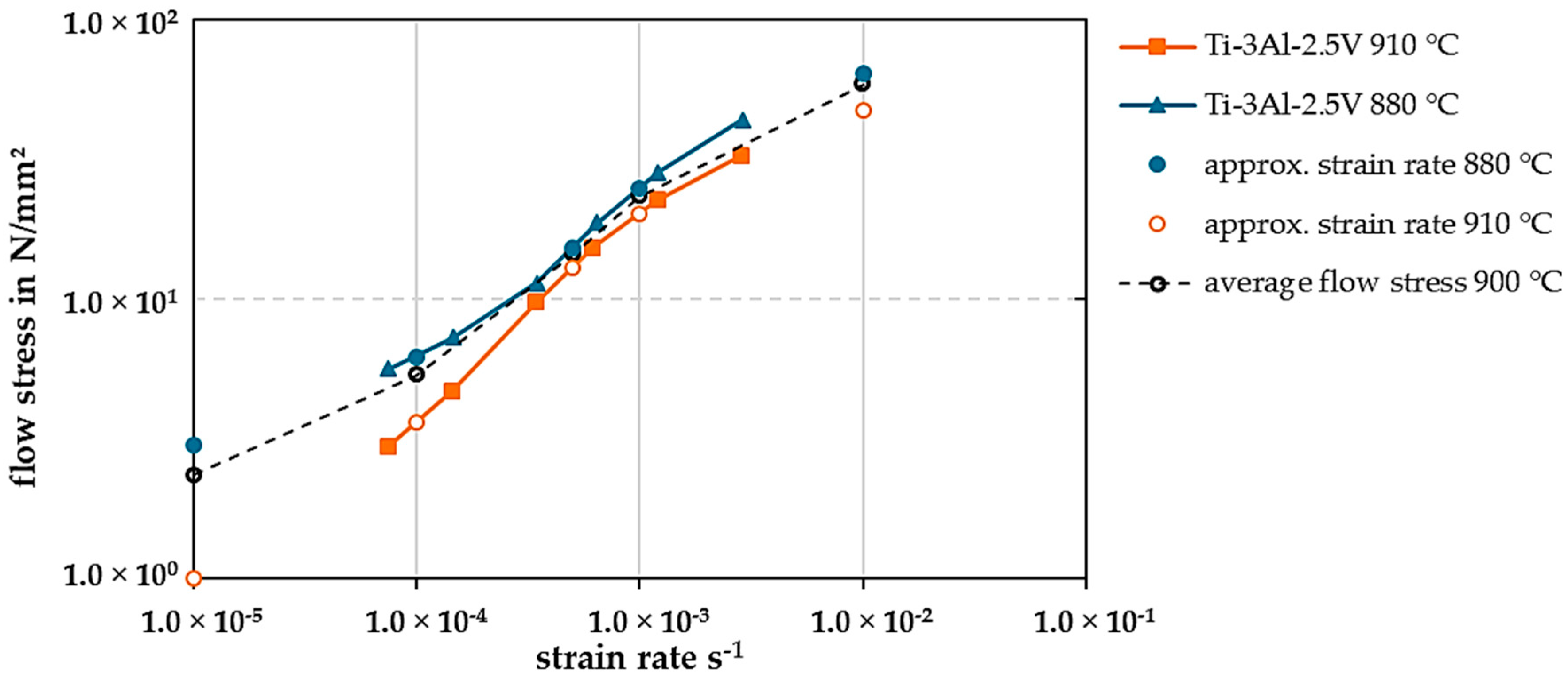
Figure 4.
Results of the simulation study: (a) forming pressure–time diagram, (b) strain rate–time diagram, (c) effective plastic strain–time diagram.
Figure 4.
Results of the simulation study: (a) forming pressure–time diagram, (b) strain rate–time diagram, (c) effective plastic strain–time diagram.

Figure 5.
Longitudinal view of several stages of the part geometry during the forming process.
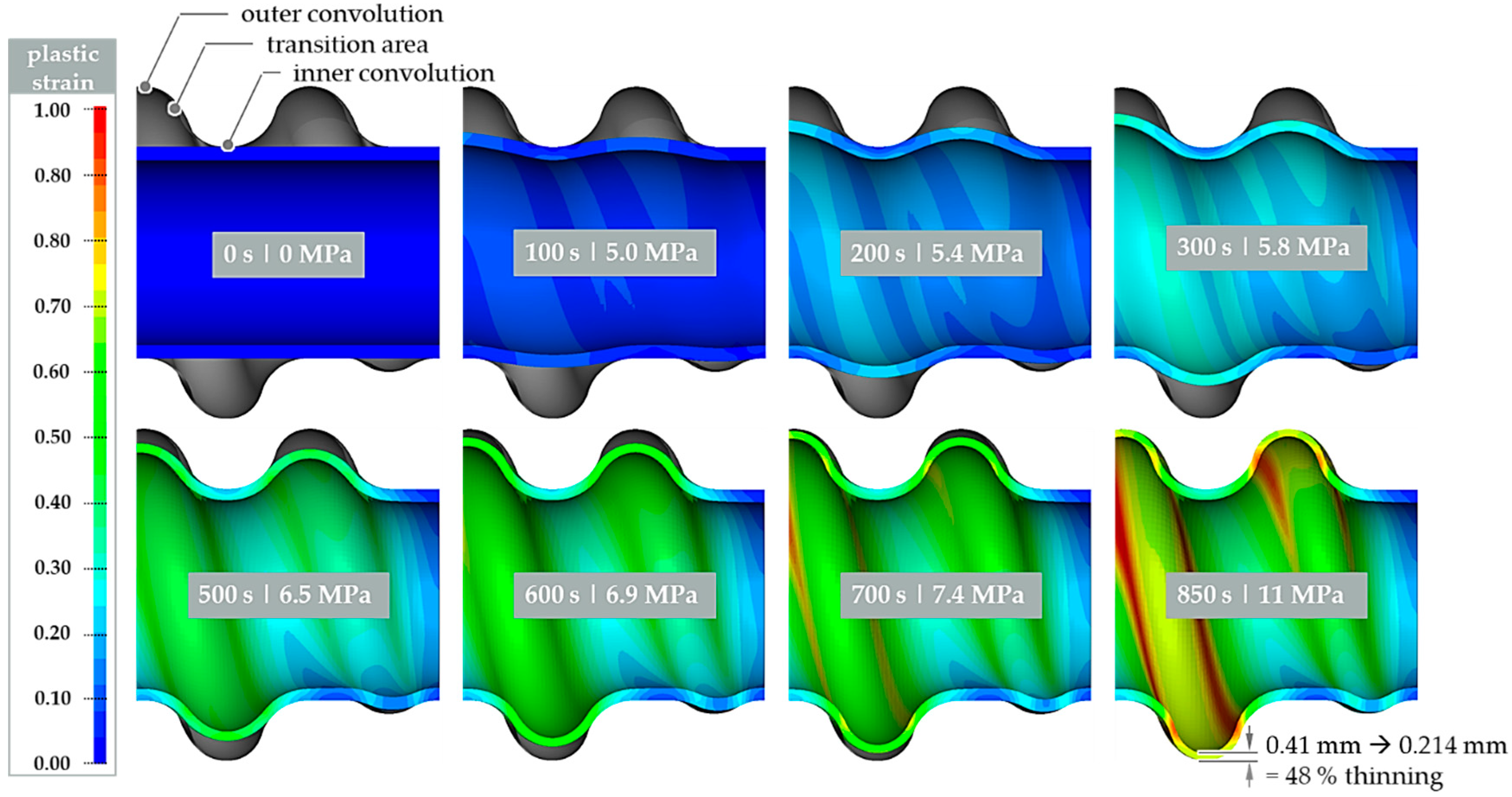
Figure 6.
Basic tool setup with implemented high temperature forming die for superplastic hot tube gas forming processes. Frontal view (left) and sectional view (right).
Figure 6.
Basic tool setup with implemented high temperature forming die for superplastic hot tube gas forming processes. Frontal view (left) and sectional view (right).

Figure 7.
Comparison between the simulated pressure–time curve and actual pressure–time curve determined within the experiments.
Figure 7.
Comparison between the simulated pressure–time curve and actual pressure–time curve determined within the experiments.
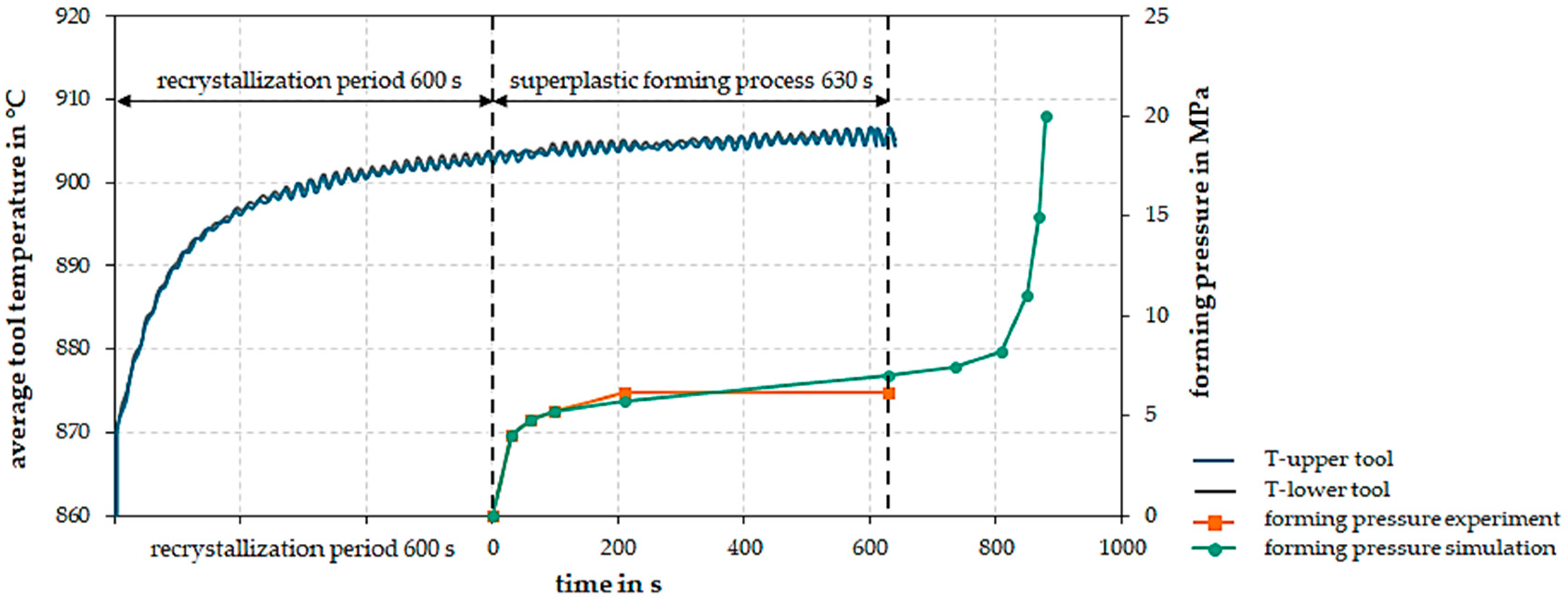
Figure 8.
Comparison between the actual forming state of the experiments (left) with the forming stage of the simulation after 780 s (right).
Figure 8.
Comparison between the actual forming state of the experiments (left) with the forming stage of the simulation after 780 s (right).
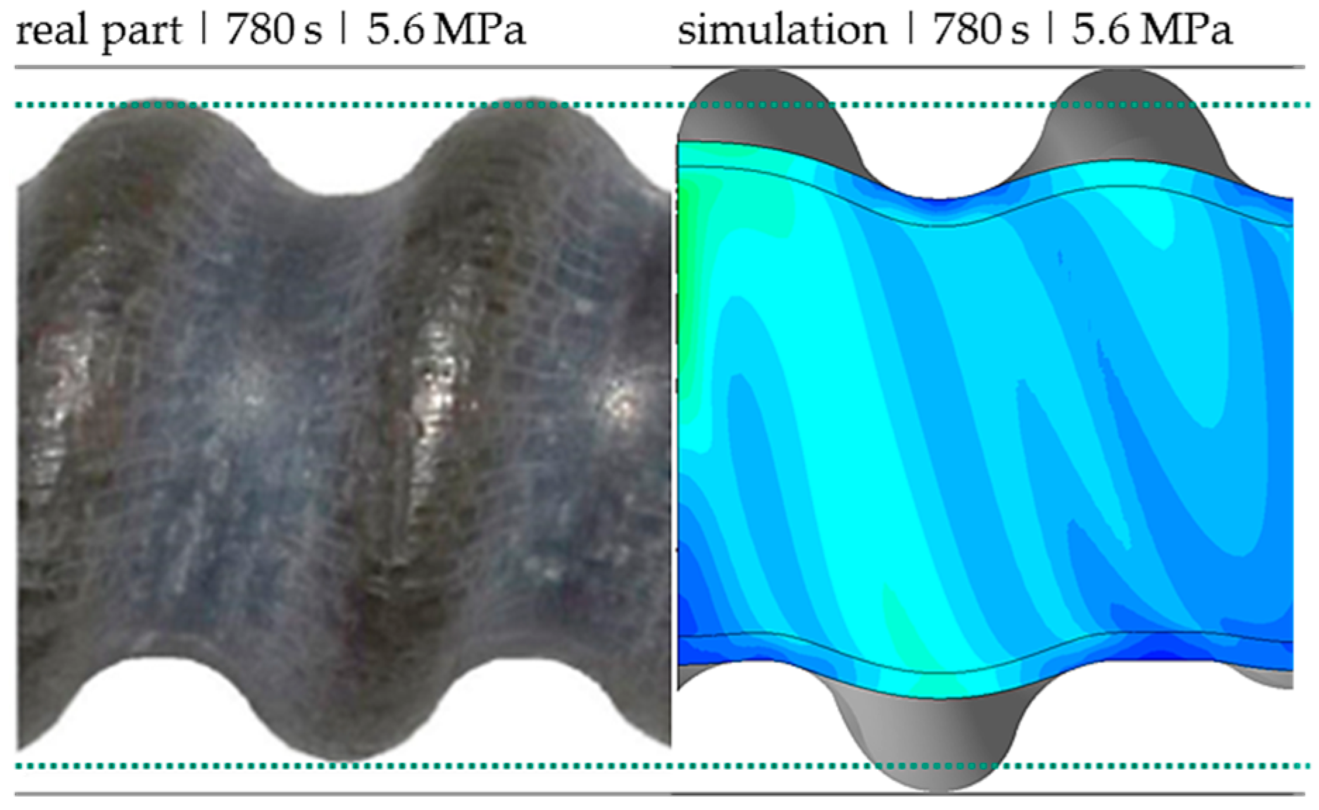
Figure 9.
Comparison between actual wall thinning (a) and simulated wall thinning (b) in the longitudinal section.
Figure 9.
Comparison between actual wall thinning (a) and simulated wall thinning (b) in the longitudinal section.
© 2020 by the authors. Licensee MDPI, Basel, Switzerland. This article is an open access article distributed under the terms and conditions of the Creative Commons Attribution (CC BY) license (http://creativecommons.org/licenses/by/4.0/).
Share and Cite
MDPI and ACS Style
Trân, R.; Reuther, F.; Winter, S.; Psyk, V. Process Development for a Superplastic Hot Tube Gas Forming Process of Titanium (Ti-3Al-2.5V) Hollow Profiles. Metals 2020, 10, 1150. https://doi.org/10.3390/met10091150
AMA Style
Trân R, Reuther F, Winter S, Psyk V. Process Development for a Superplastic Hot Tube Gas Forming Process of Titanium (Ti-3Al-2.5V) Hollow Profiles. Metals. 2020; 10(9):1150. https://doi.org/10.3390/met10091150
Chicago/Turabian StyleTrân, Ricardo, Franz Reuther, Sven Winter, and Verena Psyk. 2020. "Process Development for a Superplastic Hot Tube Gas Forming Process of Titanium (Ti-3Al-2.5V) Hollow Profiles" Metals 10, no. 9: 1150. https://doi.org/10.3390/met10091150
Note that from the first issue of 2016, this journal uses article numbers instead of page numbers. See further details here.