
Influence of Cooling Conditions on Long-Period Stacking-Ordered Phase Evolution and Corrosion Behavior of As-Cast Resoloy®


1
MeKo Laser Material Processing, 31157 Sarstedt, Germany
2
School of Mechanical Engineering, University of Applied Sciences Stralsund, 18435 Stralsund, Germany
*
Author to whom correspondence should be addressed.
Metals 2021, 11(9), 1372; https://doi.org/10.3390/met11091372
Submission received: 3 August 2021
/
Revised: 23 August 2021
/
Accepted: 27 August 2021
/
Published: 30 August 2021
(This article belongs to the Special Issue Development and Application of Biodegradable Metals)
Abstract
:This study focuses on the influence of cooling conditions on the long-period stacking-ordered (LPSO) phase evolution and corrosion behavior of as-cast Resoloy®, a bioresorbable Mg-Dy-based alloy. Metallographic and corrosive tests are used to monitor the changes in the properties of this material. The corrosion behavior is investigated by potentiodynamic polarisation. Permanent mold chill casted ingots are wire-eroded to cylindrical platelets. The eroded platelets are solution heat treated over three different time periods. Cooling is performed in two different ways: quenching in water and cooling in air at ambient temperature. The as-cast condition shows a homogeneous fine-grained microstructure. Grains become larger with increasing heat treatment duration and slow cooling leads to additional grain growth. Furthermore, cooling in air leads to faint lamellar LPSO structures, which develop from bulk LPSO structures during the cooling process. The corrosion rate of the cooled platelets increases with increasing grain size. When the lamellar LPSO structures are uniformly distributed over the entire grain, the corrosion starts at the matrix between the LPSO lamellae and stops at them. Heat treatment at 500 °C reduces the normal potential difference between matrix and secondary phase and thus weakens the galvanic corrosion.
1. Introduction
Interest in Mg alloys as bioresorbable metals has grown strongly over the last decades. Mg alloys are of interest mainly because of their biocompatibility, moderate corrosion rate and appropriate mechanical properties when the right alloying system and process parameters are used. The Mg-Dy-based alloy Resoloy® is designed for temporary cardiovascular stents [1]. The current process parameters create a microstructure that results in material properties that meet the overall requirements for a bioresorbable stent material [2]. One requirement is the moderate corrosion, which is important to ensure that the coronary vessel is kept open until the natural tissue can regain the support function previously provided by the stent [3].
In order to further optimize the material properties, heat treatments that influence the microstructure can be performed. Peng et al. studied the influence of lamellar LPSO structures on the corrosion behavior [4]. A microstructure with a small grain size, a fine distribution of the intermetallic alloying elements and uniformly distributed LPSO structures provides improved corrosion resistance [2,5]. For Mg-Gd-Y-Zn-Zr alloys, it is reported that slow cooling leads to precipitation and growth of lamellar LPSO phases across the whole grains [6]. However, there is little research on the influence of the cooling conditions after solution heat treatment of the LPSO phase evolution. Therefore, it is of great interest to study the microstructure after solution heat treatment and different cooling conditions and its influence on the corrosion behavior.
A binary Mg alloy with 10 wt.% Dy can be completely solution heat treated above 470 °C [7]. The addition of Zn lowers the solidus temperature so that the temperature range in which solution heat treatment can take place gets smaller. In addition to Zn and Dy, Resoloy® also contains a small amount of Nd (1 wt.%). This ensures that the solidus temperature drops to a value of about 510 °C and that complete solution heat treatment is no longer possible. Below 510 °C, a small amount of the intermetallic compound Mg41Nd5 is always present [8]. Therefore, it is not possible to dissolve all secondary phases completely without melting.
In this study, as-cast Resoloy® was heat treated with different process parameters, especially with different cooling conditions to produce various LPSO structures and to investigate the microstructure and corrosion behavior in dependence of their morphology.
2. Materials and Methods
Resoloy® (Mg-10Dy-1Nd-1Zn-0.2Zr, where chemical composition is given in weight percent) was cast using permanent mold direct chill casting [9]. For the investigation of the influence of cooling conditions after solution heat treatment of the microstructure of the as-cast ingots, cylindrical platelets with the dimensions 10 mm × 3 mm (D × H) were wire-eroded from the as-cast ingot. To prevent melting and to keep the amount of the intermetallic compound Mg41Nd5 low, a temperature of 500 °C was chosen for the solution heat treatments, performed over three different time periods: 1 h, 24 h and 96 h. Cooling was performed in two different ways: quenching in water and cooling in air at ambient temperature (see Table 1). Both water and air were at ambient temperature (approx. 25 °C). After quenching, the platelets remained in the water for about 3 min. For cooling in air, the platelets were placed on a stainless steel table.
For the metallographic investigations, the platelets were prepared by embedding in epoxy resin (EpoThin 2, Buehler Ltd., Lake Bluff, IL, USA) and grinding with SiC paper (Presi GmbH, Hagen, Germany) to a grit size of 4000. Afterwards, the platelets were polished on a SiO2 polishing cloth (Buehler Ltd., Lake Bluff, IL, USA) with 1 µm monocrystalline diamond suspension (Schmitz Metallographie GmbH, Herzogenrath, Germany), cleaned with ethanol and dried with compressed air. For analysis with scanning electron microscopy (SEM) a Tescan Vega 3 was used (Tescan, Brno, Czech Republic). The attached energy dispersive X-ray spectroscopy (EDS) system was used to analyse the chemical composition by point detection. Then the platelets were etched in a solution prepared with 4.2 g picric acid, 10 mL acetic acid 100%, 70 mL ethanol and 10 mL distilled water. After etching, the platelets were examined with light microscopy (Axio Scope.A1, Carl Zeiss AG, Oberkochen, Germany). µGrain software was used for the measurement of the grain size using the line intercept technique.
In order to check the corrosive properties of the material in dependence of the heat treatment duration and the cooling conditions, potentiodynamic polarisations were carried out in addition to metallographic characterisations. The wire-eroded platelets were pickled with H3PO4 to remove the passive layer. During the corrosion tests, they were immersed at 37 °C in 0.5 l phosphate-buffered saline (PBS) at pH 7.40. Before carrying out the potentiodynamic polarisation, the Open Circuit Potential of the corroding platelets was measured for 30 min under currentless conditions. The measurement was taken against the calomel reference electrode as a function of time. Then the potentiodynamic polarisation started at an electrode potential of V and was continued with 1 mV/s. The electrode potential was controlled and the resulting current was measured until an electrode potential of 1 V was reached and the polarisation stopped.
After the potentiodynamic polarisation, the platelets were soaked in chromic acid (H2CrO4) to remove the corrosion products and a Tafel extrapolation was carried out. The Tafel slopes of the polarisation curves define the susceptibility to anodic and cathodic processes. The resulting Tafel equations for the anodic and cathodic reactions can be summarised in the Butler–Voltmer equation [10]:
where I is the measured current, A; is the corrosion current, A; E is the applied electrical potential, V; is the corrosion potential, V; and are the anodic and cathodic Tafel slope, V/dec. The corrosion rate was then calculated via equation [10]:
where is the corrosion rate, mm/a; K is a constant; is the equivalent weight, g/val; is the density, g/cm and A is the surface of the platelet, cm.
3. Results and Discussion
3.1. Microstructure
The bar chart in Figure 1 shows the average grain sizes of the quenched and the cooled platelets. The average grain size of as-cast Resoloy® (Reference) is 51.05 ± 8.91 µm. Quenching in water after heat treatment does not change the grain size significantly. The average grain sizes are 37.00 ± 3.91 µm for W1, 50.00 ± 7.97 µm for W24 and 64.38 ± 21.35 µm for W96. In contrast, slow cooling in air does change the grain size more remarkable. The average grain sizes are 81.36 ± 32.92 µm for A1, 129.95 ± 43.72 µm for A24 and 154.17 ± 46.51 µm for A96. That means that slow cooling leads to larger grains than fast cooling. Despite partially high standard deviations, it is noticeable among both the cooled and the quenched platelets that the grains become larger with increasing heat treatment duration. This observation was also made by Maier et al. and Steinacker et al. [2,5].
The as-cast Resoloy® shows a homogeneous, small-grained recrystallized microstructure; see micrograph in Figure 2a. After a one-hour heat treatment followed by cooling in air, faint lamellar LPSO structures are visible, which become more pronounced with increasing heat treatment duration (see Figure 2b–d). The lamellar LPSO phase is uniformly distributed over the matrix of the entire grain. In the study by Steinacker et al. also an increasing number of LPSO structures is found with increasing heat treatment duration [5]. In contrast, quenching in water leads to bulk LPSO structures that become less pronounced with increasing heat treatment duration (see Figure 2e–g). This suggests that the lamellar LPSO phase is formed during cooling and that the air-cooled platelets had more time to precipitate LPSO structures than the water-quenched platelets. Studies by Fumin et al. and Xu et al. confirm this conclusion [6,11]. The precipitation of LPSO must satisfy the requirement for a combination of time and temperature. The LPSO phase is the product of diffusion transformation [11]. The appearance of stacking faults facilitate the diffusion of solute atoms [6]. Quenching therefore prevents diffusion processes and thus the re-segregation of solute atoms into the matrix.
Another suggestion is the conversion of bulk to lamellar LPSO structures during the cooling process which is reinforced by the EDS measurements performed: the lamellar LPSO phase of air-cooled platelets contains less Dy than the lamellar LPSO structure of water-quenched platelets (see Figure 3 for representative micrographs and Table 2 and Table 3). The lamellar LPSO phase thus differs less from the bulk LPSO phase after quenching than after cooling. This fits with the visual impression that the lamellar LPSO structures are only present in beginnings, after quenching. They form the transition phase between the bulk LPSO phase and the lamellar LPSO phase distributed over the matrix of the entire grain. Wu et al. previously reported the conversion of bulk to lamellar LPSO phase based on nucleation and growth [12].
3.2. Corrosion
The polarisation curves of the platelets are depicted in Figure 4. The polarisation curves of the reference platelets show that, at an electrode potential of about −1.47 V, the partial current resulting from cathodic reactions was equal to the partial current resulting from anodic reactions. This point is called corrosion potential. Higher electrode potentials caused the anodic partial current to dominate. The anodic part presents some instability between potentials of −1.2 V and 0.3 V. There, the corrosion is less uniform.
Figure 4b–e,g indicates that the corrosion potential has shifted to about −1.55 V. It is slightly less novel, but the anodic part of the curves is much more homogeneous. Figure 4f shows that cooling in air after solution heat treatment for 96 h does not change significantly the corrosion potential, but the anodic part is even more inhomogeneous. There, the corrosion morphology will be the least uniform.
The bar chart in Figure 5 shows that the corrosion rate of the reference platelets varies and is higher than the corrosion rate of the heat treated platelets. The mean corrosion rate of the reference platelets is 11.3 ± 7.1 mm/a; the mean corrosion rate of the heat treated platelets is 1.5 ± 0.7 mm/a. Among the air-cooled platelets, it is noticeable that the corrosion rate increases with longer heat treatment duration. At the same time, the number of LPSO lamellae grows (see Figure 2b–d). This correlation is contrary to the high corrosion resistance of a lamellar LPSO phase mentioned in [5]—there, the corrosion resistance is more pronounced the longer the heat treatment takes. Among the water-quenched platelets, no proportional correlation between corrosion rate and heat treatment duration is visible. Apart from sample group W24, the quenched platelets have a lower average corrosion rate than the cooled platelets. In addition, the standard deviations of sample groups W1 and W96 are significantly lower than those of sample group W24.
Regarding Figure 1 and Figure 5, the dependence of the corrosion rate on the grain size becomes visible. The corrosion rate of the air-cooled platelets increases with increasing grain size. The intensity of micro galvanic coupling between inner grain and grain boundary increases due to a reduced fraction of grain boundaries with an increasing grain size. This correlation is confirmed by the investigations of Maier et al. [2]. Since the corrosion rate increases with increasing grain size and despite the increasing amount of lamellar LPSO structures, it can be stated that the grain size affects the corrosion rate of Resoloy® more than the lamellar LPSO structures in this case. The strong dependence of the corrosion rate on grain size is also suspected for the water-quenched platelets, but cannot be definitively confirmed yet due to the deviation from sample group W24.
However, independent of the increase of the corrosion rate with increasing grain size within the group of air-cooled or water-quenched conditions, the water-quenched platelets show a lower corrosion rate, when taking the error bars into account. Here, the platelets from sample group A96 stand out with their high corrosion rate (see Figure 5) based on the highest grain size (see Figure 1). Besides the lower grain size of the water-quenched platelets, the appearance of lamellar and bulk LPSO phases is an advantage, see Figure 3d. Furthermore, the chemical composition of the lamellar and bulk LPSO phase differs less after quenching than after cooling (see Table 2 and Table 3), so the intensity of micro galvanic coupling is lower.
In addition to the grain size, the corrosion rate also depends on the chemical composition—the quenched platelets have almost the same grain size as the reference platelets, but the corrosion rate of the quenched platelets is lower than that of the reference platelets. The difference in chemical composition is caused by the Mg content of the matrix. Due to the conversion of eutectics into LPSO structures during solution heat treatment, the matrix of the heat treated platelets has—independent of the cooling conditions—a lower Mg content and a higher alloying element content compared to the reference platelets (see Table 2, Table 3 and Table 4). While the matrix of the heat treated platelets consists on average of 88.5 ± 0.4 wt.% Mg and 11.5 ± 0.4 wt.% alloying elements, the matrix of the reference platelets consists of 94.3 ± 0.5 wt.% Mg and 5.7 ± 0.5 wt.% alloying elements. It can be concluded that the normal potential difference between the matrix and the secondary phase is smaller in the heat treated platelets than in the reference platelets. Accordingly, the corrosion rate of the heat treated platelets is lower than that of the reference platelets because the normal potentials of the different phases in the material are closer together, resulting in weaker galvanic effects [13]. This slows down the corrosion of the heat treated platelets compared to that of the reference platelets.
Since the corrosion rate of both the water-quenched and the air-cooled platelets is below the corrosion rate of the reference platelets, it can be assumed that the LPSO phases of the quenched and the cooled platelets have served as a barrier against corrosion instead of enhancing corrosion. This is also confirmed by the large amount and continuity of the LPSO phases visible in the SE images after potentiodynamic polarisation and soaking in chromic acid (see Figure 6). During the potentiodynamic polarisation, passivation processes happen on the metal surface, which are the result of increasing applied current.
The SE images show the topography of the corroded surface of the platelets. The structures visible on the SE images are mostly secondary and LPSO phases, which are known to have a higher normal potential than the matrix and therefore have a cathodic effect on it. The secondary phases are more corrosion resistant than the matrix [13,14]. Therefore, mainly the secondary phases are present after the potentiodynamic polarisation and form the top layer of the corroded surface. The Mg-matrix corrodes first.
On the surface of the air-cooled platelets, strongly aligned structures are visible (see Figure 6b–d, marked in red), which change their orientation at grain boundaries. A layered structure of the corrosion morphology becomes visible. The shape, distribution and chemical composition of these aligned structures agree with the lamellar LPSO structures described before (see Figure 2b–d and Table 5).
On the surface of the water-quenched platelets, no lamellar LPSO structures are visible (see Figure 6e–g). This observation confirms the evaluation of the light microscopy images before potentiodynamic polarisation (see Figure 2e–g). The topography of the platelets from sample group W24 deviates strongly from the topography of the other quenched platelets. This deviation was already observed during the presentation of the corrosion rates.
4. Conclusions
The influence of cooling conditions on LPSO phase evolution and corrosion behavior of as-cast Resoloy® has been studied using light microscopy, line intercept technique, SEM and potentiodynamic polarisation. The following conclusions can be drawn:
- (1)
- Cooling in air leads to larger grains than quenching in water and an increasing heat treatment duration leads to increasing grain sizes;
- (2)
- The lamellar LPSO phase forms during cooling by diffusion processes and re-segregation of solute atoms into the matrix;
- (3)
- Lamellar LPSO structures develop from bulk LPSO structures during cooling;
- (4)
- The corrosion rate of solution heat treated and air-cooled Resoloy® increases with increasing grain size, but is significantly lower than the corrosion rate of the as-cast condition;
- (5)
- Solution heat treatment at 500 °C shifts the corrosion potential towards slightly less nobler potentials and results in a more homogenous anodic part of the polarisation curve;
- (6)
- Corrosion starts at the matrix between the LPSO lamellae. These lamellae hinder further corrosion, if they are uniformly distributed over the matrix of the entire grain. The layered structure of the surface makes the more resistant cathodic structures visible.
Author Contributions
Conceptualization, B.B.; methodology, B.B.; validation, B.B.; formal analysis, B.B. and P.M.; investigation, S.A.; data curation, S.A.; writing—original draft preparation, S.A.; writing—review and editing, B.B. and P.M.; visualization, S.A.; project administration, S.A. and B.B. All authors have read and agreed to the published version of the manuscript.
Funding
This research received no external funding.
Institutional Review Board Statement
Not applicable.
Informed Consent Statement
Not applicable.
Data Availability Statement
Not applicable.
Acknowledgments
The authors acknowledge Roman Menze and Heinke Brosig (MeKo Laser Material Processing, 31157 Sarstedt, Germany) for the helpful suggestions and constructive cristics. Furthermore, Boris Frumkin (MeKo Laser Material Processing, 31157 Sarstedt, Germany) is thanked for supporting the corrosive testing.
Conflicts of Interest
The authors declare no conflict of interest.
References
- Stekker, M. Magnesium Alloy and Resorbable Stents Containing the Same. Patent No. EP2744531B1, 15 August 2012. [Google Scholar]
- Maier, P.; Steinacker, A.; Clausius, B.; Hort, N. Influence of Solution Heat Treatment on the Microstructure, Hardness and Stress Corrosion Behavior of Extruded Resoloy. JOM 2020, 72, 1870–1879. [Google Scholar] [CrossRef] [Green Version]
- Heiden, M.; Walker, E.; Stancui, L. Magnesium, Iron and Zinc Alloys, the Trifecta of Bioresorbable Orthopaedic and Vascular Implantation—A Review. J. Biotechnol. Biomater. 2015, 5, 2–9. [Google Scholar]
- Peng, Q.; Guo, J.; Fu, H.; Cai, X.; Wang, Y.; Lui, B.; Xu, Z. Degradation behavior of Mg-based biomaterials containing different long-period stacking ordered phases. Sci. Rep. 2014, 4, 3620. [Google Scholar] [CrossRef] [PubMed] [Green Version]
- Steinacker, A.; Mendis, C.; Mohedano, M.; Feyerabend, F.; Stekker, M.; Maier, P.; Kainer, K.U.; Hort, N. Microstructure evolution and corrosion behaviour of the biodegradable EZK1110 alloy. Eur. Cells Mater. 2016, 32, 11. [Google Scholar]
- Xu, C.; Nakata, T.; Xiaoguang, Q.; Mingyi, Z.; Kun, W.; Kamado, S. Effect of LPSO and SFs on microstructure evolution and mechanical properties of Mg-Gd-Y-Zn-Zr alloy. Sci. Rep. 2017, 7, 40846. [Google Scholar] [CrossRef] [PubMed]
- Yang, L.; Huang, Y.; Feyerabend, F.; Willumeit, R.; Kainer, K.U.; Hort, N. Influence of ageing treatment on microstructure, mechanical and bio-corrosion properties of Mg–Dy alloys. J. Mech. Behav. Biomed. Mater. 2012, 13, 36–44. [Google Scholar] [CrossRef] [PubMed]
- Smola, B.; Stulikova, I.; Cerna, J.; Cizek, J.; Vlach, M. Phase transformations in MgTbNd alloy. Phys. Status Solidi A 2011, 208, 2741–2748. [Google Scholar] [CrossRef]
- Elsayed, F.R.; Hort, N.; Ordorica, M.A.; Kainer, K.U. Magnesium Permanent Mold Castings Optimization. Mater. Sci. Forum 2011, 690, 65–68. [Google Scholar] [CrossRef] [Green Version]
- Getting Started with Electrochemical Corrosion Measurement. Available online: https://www.gamry.com/application-notes/corrosion-coatings/basics-of-electrochemical-corrosion-measurements/ (accessed on 13 October 2020).
- Fumin, L.; Aibin, M.; Jinghua, J.; Donghuib, Y.; Qi, Z. Review on long-period stacking-ordered structures in Mg-Zn-RE alloys. Rare Met. 2012, 31, 303–310. [Google Scholar]
- Wu, Y.; Zeng, X.; Lin, D.; Peng, L.; Ding, W. The microstructure evolution with lamellar 14H-type LPSO structure in an Mg96.5Gd2.5Zn1 alloy during solid solution heat treatment at 773K. J. Alloys Compd. 2008, 477, 193–197. [Google Scholar] [CrossRef]
- Song, G.-L. Corrosion Prevention of Magnesium Alloys, 1st ed.; Woodhead Publishing Ltd.: Cambridge, UK, 2013; pp. 509–517. [Google Scholar]
- Li, C.Q.; Xu, D.K.; Zeng, Z.R.; Wang, B.J.; Sheng, L.Y.; Chen, X.-B.; Han, E.H. Effect of volume fraction of LPSO phases on corrosion and mechanical properties of Mg–Zn–Y alloys. Mater. Des. 2017, 121, 430–441. [Google Scholar] [CrossRef]
Figure 1.
Grain size of the platelets as a function of the solution heat treatment duration and cooling conditions, taking into account the standard deviation and the sample size (n = 3).
Figure 1.
Grain size of the platelets as a function of the solution heat treatment duration and cooling conditions, taking into account the standard deviation and the sample size (n = 3).
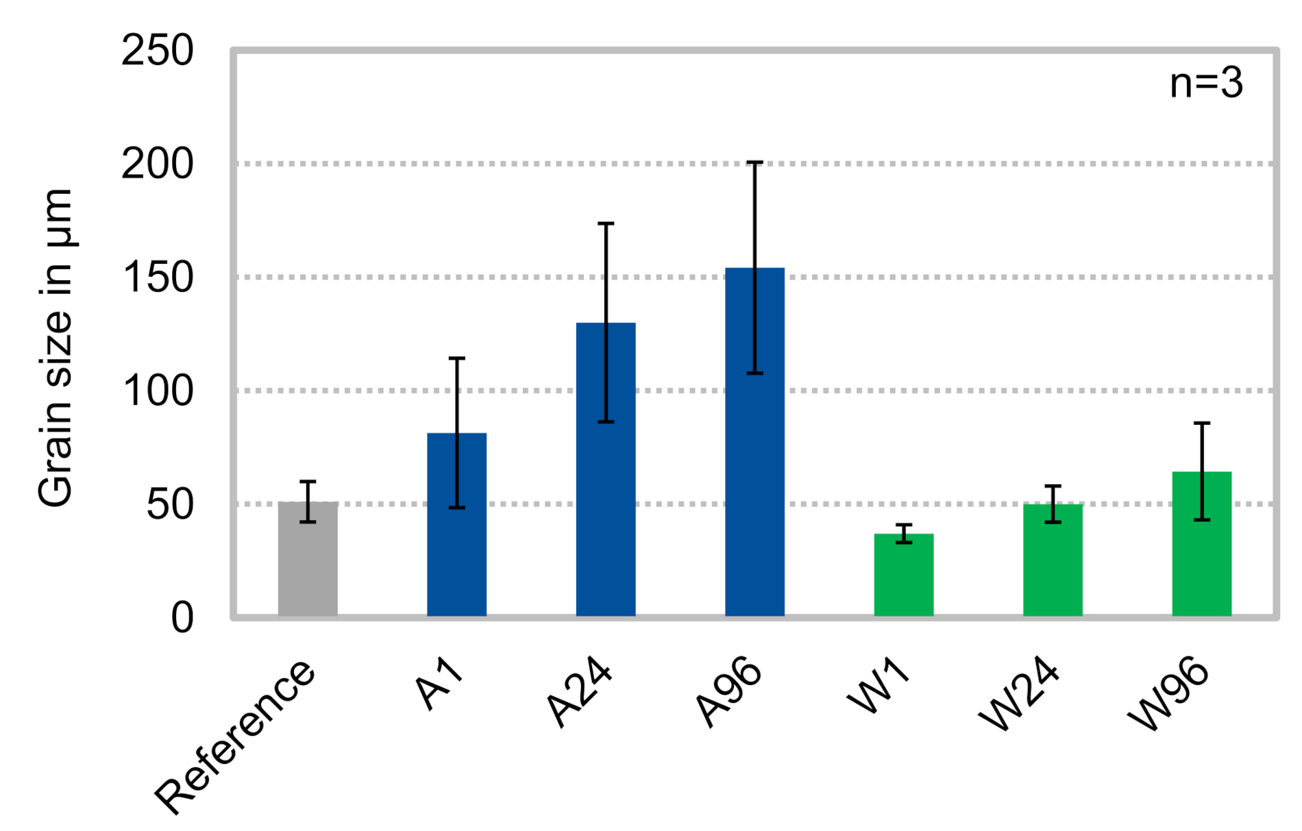
Figure 2.
Light microscopy images of the platelets depending on the heat treatment duration and the cooling conditions (a–g).
Figure 2.
Light microscopy images of the platelets depending on the heat treatment duration and the cooling conditions (a–g).
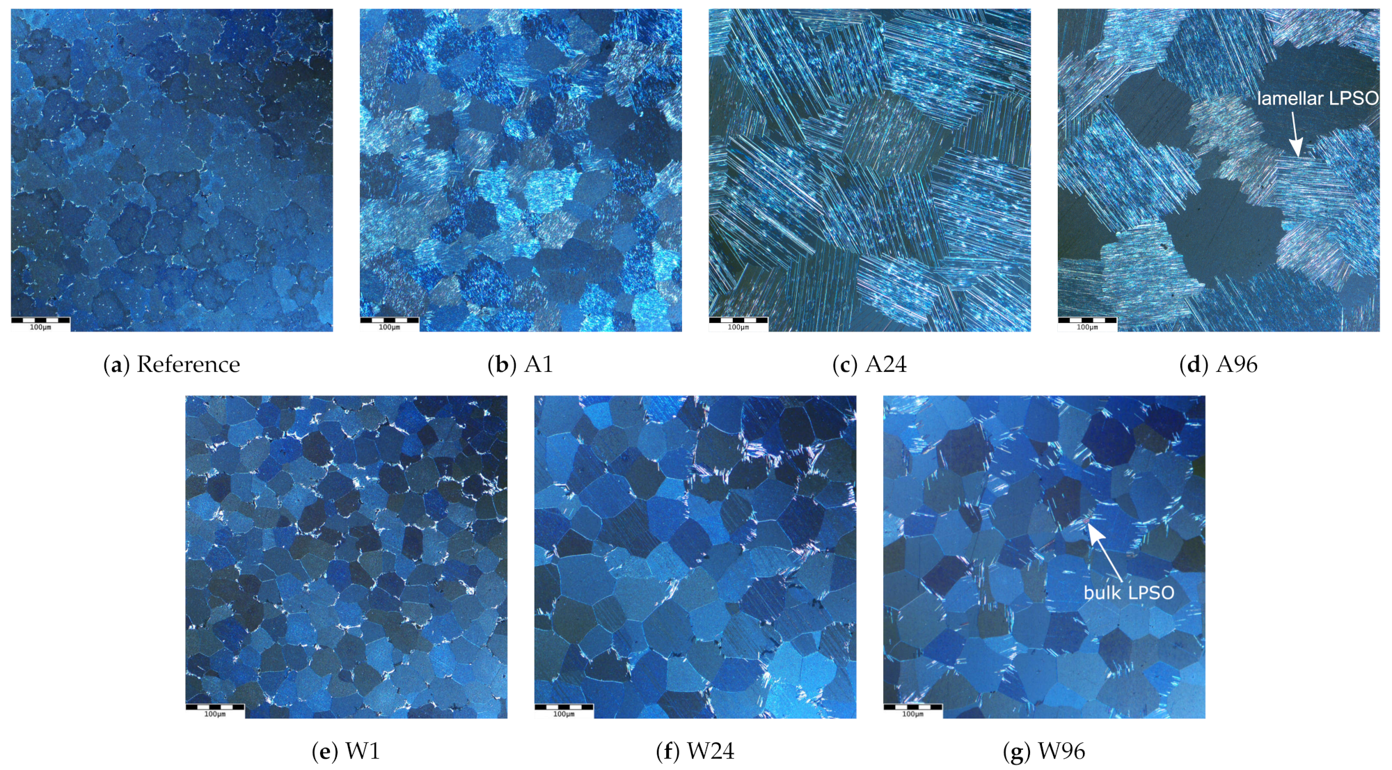
Figure 3.
Exemplary SEM images of the phases in air-cooled platelets from sample group (a) A24 and (b) A96 and water-quenched platelets from sample group (c) W24 and (d) W96. The platelets are shown in longitudinal section. The small pictures in the top right corner show the platelets at higher magnification.
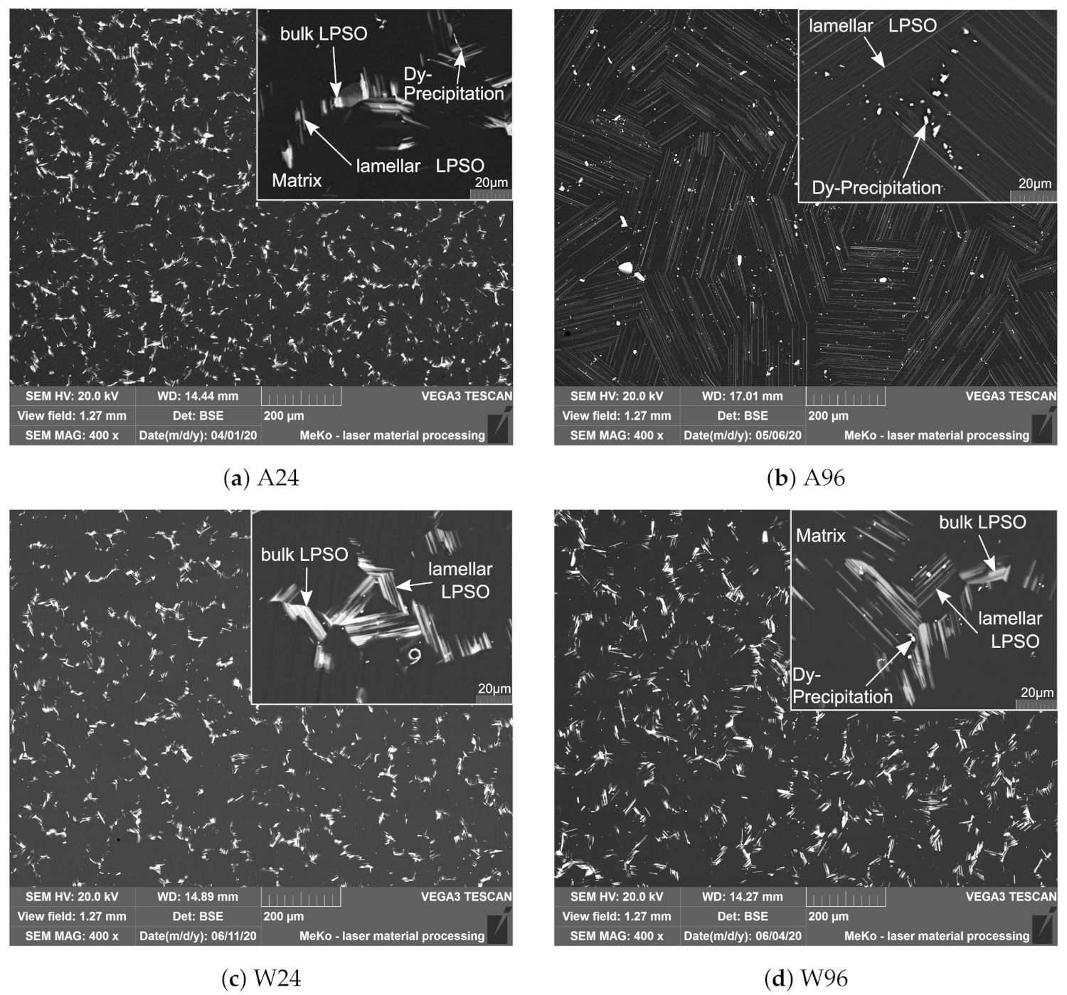
Figure 4.
Polarisation curves of the platelets in dependence of the heat treatment duration and the cooling condition (n = 3 to 5). The electrode potential (in V) is plotted as a function of current density (in A/cm). The current density is plotted logarithmically.
Figure 4.
Polarisation curves of the platelets in dependence of the heat treatment duration and the cooling condition (n = 3 to 5). The electrode potential (in V) is plotted as a function of current density (in A/cm). The current density is plotted logarithmically.
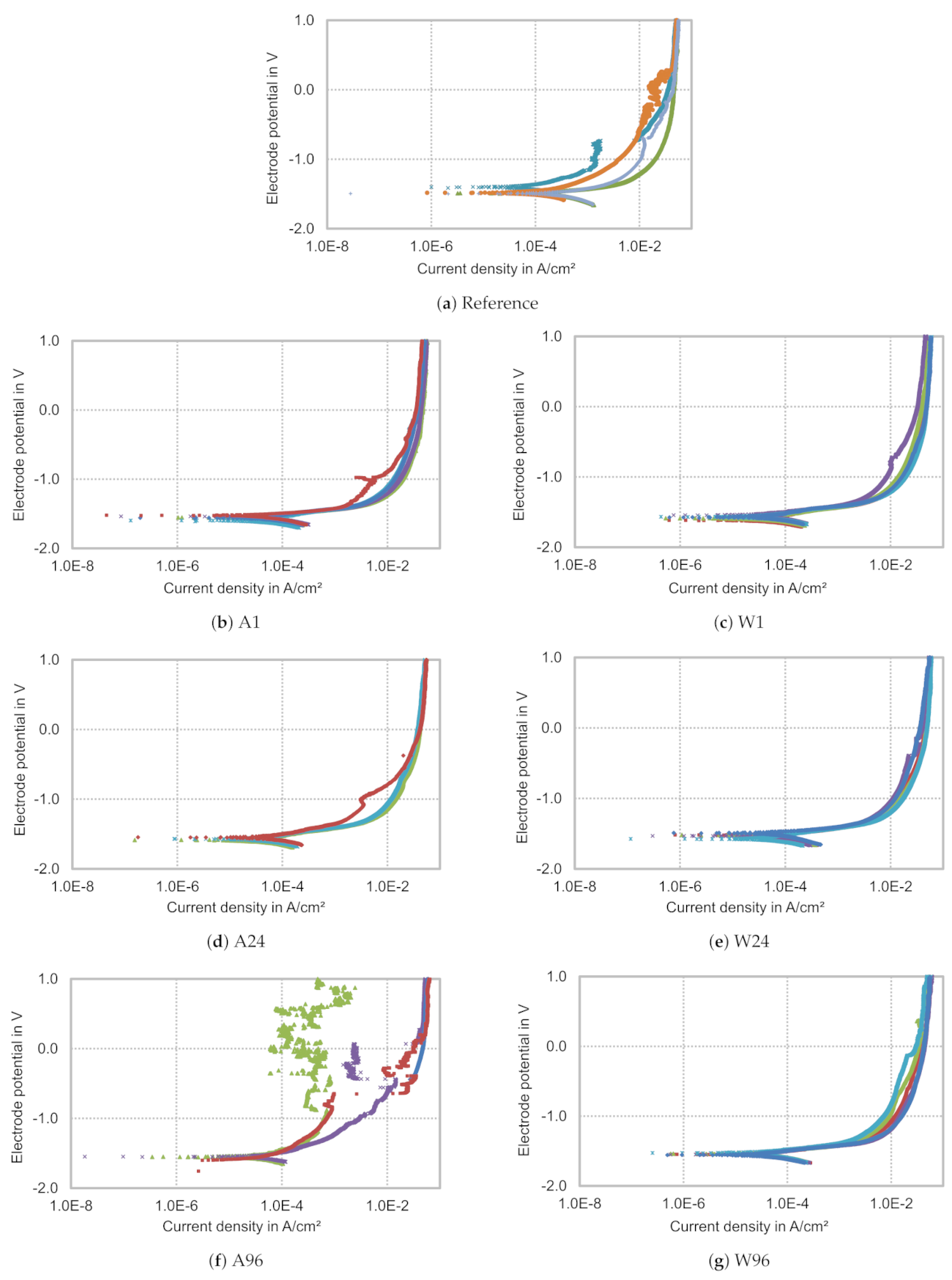
Figure 5.
Corrosion rates of the platelets (in mm/a) during potentiodynamic polarisation as a function of heat treatment and cooling conditions.
Figure 5.
Corrosion rates of the platelets (in mm/a) during potentiodynamic polarisation as a function of heat treatment and cooling conditions.
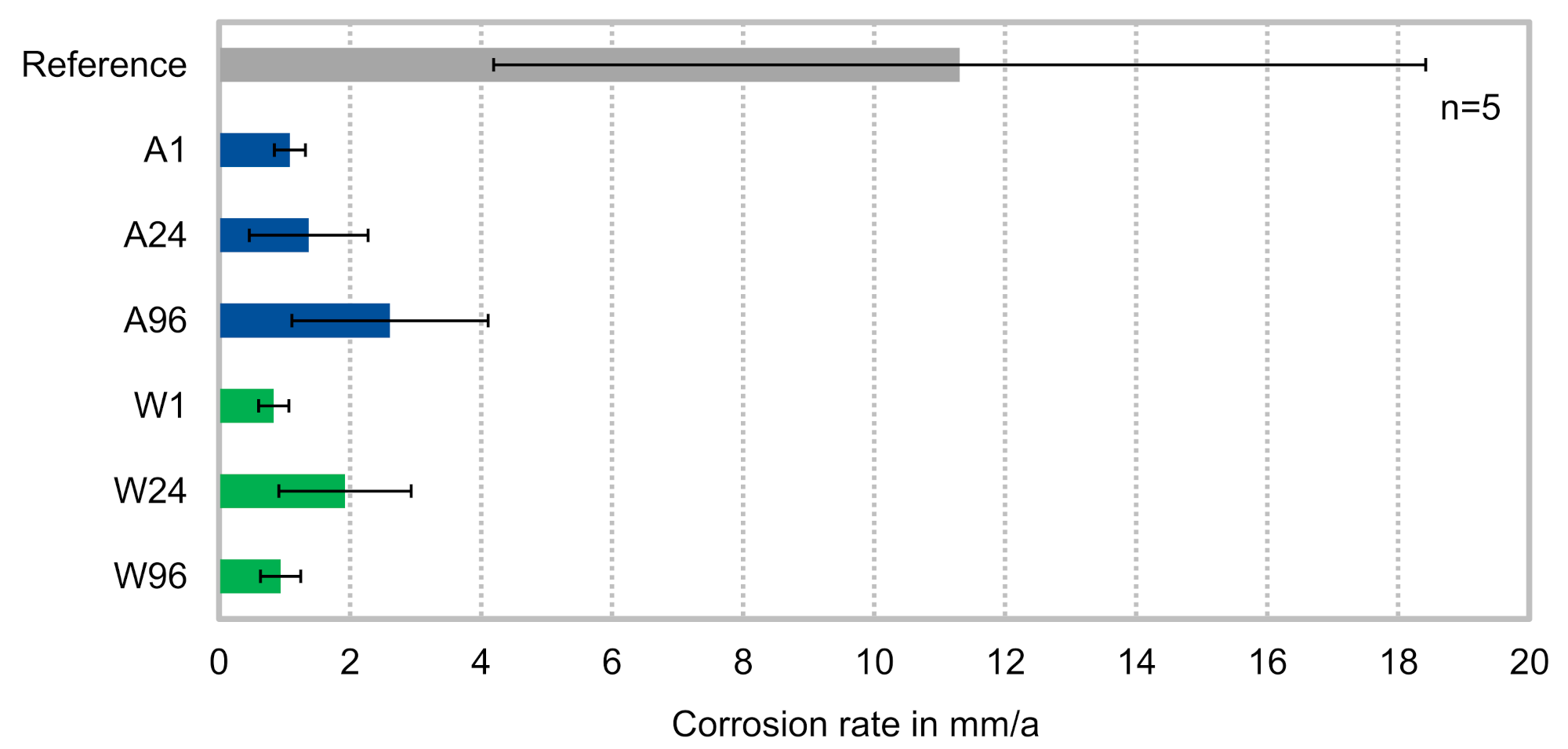
Figure 6.
SE images of the platelets after potentiodynamic polarisation in dependence of the heat treatment duration and the cooling condition. All platelets are shown in longitudinal section. (b–d) feature strongly aligned structures (marked in red).
Figure 6.
SE images of the platelets after potentiodynamic polarisation in dependence of the heat treatment duration and the cooling condition. All platelets are shown in longitudinal section. (b–d) feature strongly aligned structures (marked in red).


Table 1.
Overview of the heat treatment parameters investigated and assignment to the sample group (e.g., A1 for 1 h heat treated with subsequent cooling in air). All heat treatments were carried out at 500 °C.
Table 1.
Overview of the heat treatment parameters investigated and assignment to the sample group (e.g., A1 for 1 h heat treated with subsequent cooling in air). All heat treatments were carried out at 500 °C.
| Heat Treatment Duration | |||
|---|---|---|---|
| 1 h | 24 h | 96 h | |
| Cooled in air | A1 | A24 | A96 |
| Quenched in water | W1 | W24 | W96 |
Table 2.
Chemical composition of the different phases found on average in air-cooled platelets in wt.% with indication of the standard deviation (n = 3).
Table 2.
Chemical composition of the different phases found on average in air-cooled platelets in wt.% with indication of the standard deviation (n = 3).
| Element | Matrix | Bulk LPSO | Lamellar LPSO | Segregation |
|---|---|---|---|---|
| Mg | 88.4 ± 0.3 | 65.7 ± 0.3 | 86.8 ± 1.2 | 24.7 ± 1.3 |
| Zn | 1.0 ± 0.1 | 7.1 ± 0.2 | 1.4 ± 0.4 | 1.7 ± 1.2 |
| Zr | 0.1 ± 0.1 | 0.1 ± 0.0 | 0.1 ± 0.1 | 0.0 ± 0.0 |
| Nd | 0.8 ± 0.2 | 2.0 ± 0.1 | 0.9 ± 0.0 | 1.2 ± 0.3 |
| Dy | 9.7 ± 0.1 | 25.0 ± 0.3 | 10.8 ± 0.8 | 72.4 ± 0.1 |
Table 3.
Chemical composition of the different phases found on average in water-quenched platelets in wt.% with indication of the standard deviation (n = 3).
Table 3.
Chemical composition of the different phases found on average in water-quenched platelets in wt.% with indication of the standard deviation (n = 3).
| Element | Matrix | Bulk LPSO | Lamellar LPSO | Segregation |
|---|---|---|---|---|
| Mg | 88.6 ± 0.2 | 63.4 ± 0.5 | 72.2 ± 0.2 | 12.2 ± 0.2 |
| Zn | 0.8 ± 0.0 | 7.9 ± 0.1 | 5.3 ± 0.2 | 0.7 ± 0.3 |
| Zr | 0.1 ± 0.0 | 0.1 ± 0.1 | 0.0 ± 0.0 | 0.0 ± 0.0 |
| Nd | 0.8 ± 0.1 | 2.2 ± 0.0 | 1.7 ± 0.1 | 1.1 ± 0.1 |
| Dy | 9.7 ± 0.3 | 26.5 ± 0.4 | 20.7 ± 0.2 | 85.9 ± 5.4 |
Table 4.
Chemical composition of the different phases found on average in reference platelets in wt.% with indication of the standard deviation (n = 3).
Table 4.
Chemical composition of the different phases found on average in reference platelets in wt.% with indication of the standard deviation (n = 3).
| Element | Matrix | Eutectics |
|---|---|---|
| Mg | 94.3 ± 0.5 | 56.1 ± 5.0 |
| Zn | 0.3 ± 0.0 | 7.5 ± 1.4 |
| Zr | 0.2 ± 0.1 | 0.0 ± 0.0 |
| Nd | 0.2 ± 0.1 | 5.8 ± 1.2 |
| Dy | 5.1 ± 0.6 | 30.6 ± 2.7 |
Table 5.
Comparison between the chemical compositions of the lamellar LPSO structures found in the air-cooled platelets and the aligned structures after potentiodynamic polarisation in wt.% with indication of the standard deviation (n = 3).
Table 5.
Comparison between the chemical compositions of the lamellar LPSO structures found in the air-cooled platelets and the aligned structures after potentiodynamic polarisation in wt.% with indication of the standard deviation (n = 3).
| Element | Lamellar LPSO | Aligned Structure |
|---|---|---|
| Mg | 86.8 ± 1.2 | 86.6 ± 1.0 |
| Zn | 1.4 ± 0.4 | 1.3 ± 0.4 |
| Zr | 0.1 ± 0.1 | 0.1 ± 0.1 |
| Nd | 0.9 ± 0.0 | 0.7 ± 0.1 |
| Dy | 10.8 ± 0.8 | 11.2 ± 0.6 |
Publisher’s Note: MDPI stays neutral with regard to jurisdictional claims in published maps and institutional affiliations. |
© 2021 by the authors. Licensee MDPI, Basel, Switzerland. This article is an open access article distributed under the terms and conditions of the Creative Commons Attribution (CC BY) license (https://creativecommons.org/licenses/by/4.0/).
Share and Cite
MDPI and ACS Style
Ahlers, S.; Bittner, B.; Maier, P. Influence of Cooling Conditions on Long-Period Stacking-Ordered Phase Evolution and Corrosion Behavior of As-Cast Resoloy®. Metals 2021, 11, 1372. https://doi.org/10.3390/met11091372
AMA Style
Ahlers S, Bittner B, Maier P. Influence of Cooling Conditions on Long-Period Stacking-Ordered Phase Evolution and Corrosion Behavior of As-Cast Resoloy®. Metals. 2021; 11(9):1372. https://doi.org/10.3390/met11091372
Chicago/Turabian StyleAhlers, Sandra, Benjamin Bittner, and Petra Maier. 2021. "Influence of Cooling Conditions on Long-Period Stacking-Ordered Phase Evolution and Corrosion Behavior of As-Cast Resoloy®" Metals 11, no. 9: 1372. https://doi.org/10.3390/met11091372
Note that from the first issue of 2016, this journal uses article numbers instead of page numbers. See further details here.