
Preparation of Ag0 Nanoparticles by EDM Method as Catalysts for Oxygen Reduction

School of Materials Science and Engineering, Hebei University of Technology, 8 Guangrong Road, Tianjin 300132, China
*
Author to whom correspondence should be addressed.
Metals 2021, 11(9), 1491; https://doi.org/10.3390/met11091491
Submission received: 23 August 2021
/
Revised: 14 September 2021
/
Accepted: 18 September 2021
/
Published: 20 September 2021
(This article belongs to the Special Issue Research on Metal Nanoparticles)
Abstract
:At present, platinum-based catalysts are the best cathode catalysts, but due to their high prices, they are difficult to use widely. Under alkaline conditions, silver is a better low-cost substitute. Here, a physical preparation method—electrical discharge machining (EDM)—is used to prepare Ag0 nanoparticles. The method is simple and has a high yield. The diameter of prepared nanoparticles is about 30 nm and the nanoparticle surface is rich in defects. These defects enhance the adsorption of O2. In addition, defects can cause tensile strain on the silver catalyst, causing the d-band center of silver to move upward. The defects and the upward shift of the d-band center jointly improve the adsorption energy and catalytic performance of Ag0. This work provides a new method for the engineering construction of surface defects and the preparation of metal catalysts.
1. Introduction
The rapid growth of global demand for energy and the massive consumption of traditional fossil fuels are driving people to seek new sources of clean energy. Among these, high energy density fuel cells are an advanced energy storage and conversion device for meeting the requirements of environmentally sustainable energy [1,2]. However, the power of the fuel cell stack is often affected by the slow kinetics of the cathode oxygen reduction reaction (ORR), resulting in an energy conversion efficiency far from the thermodynamic ideal [3]. Platinum-based catalysts are one of the most efficient ORR catalysts yet discovered, and can effectively reduce the energy barrier and greatly improve the conversion efficiency. However, due to their high cost and scarcity, large-scale commercial application remains a huge challenge. It is necessary to search for non-platinum-based catalysts with excellent catalytic performance. Low-priced metal oxides [4,5], nitrides [6,7], sulfides [8,9] and silver-based catalysts [10,11,12] have broad prospects. Among them, silver-based catalysts have shown good ORR activity under alkaline conditions [13]. Moreover, silver has good electrical conductivity and its price is about a fiftieth of the price of platinum [14], which makes silver an attractive low-cost alternative. However, the adsorption capacity of silver for O2 is weak, and the catalytic activity of silver is not as excellent as that of platinum, so the adjustment of silver’s properties is necessary.
The strain effect is an effective strategy to improve catalyst activity [15]. For a transition metal with more than half of the d-band filled, under tensile strain, the center of the d-band moves upward relative to the Fermi level, resulting in a decrease in the occupancy rate of the antibonding states below the Fermi level, thus increasing the adsorption energy of the intermediate reaction [16,17,18]. For example, cobalt (II) oxide, an inactive HER material, changes the adsorption energy of hydrogen by introducing a tensile strain on the surface, allowing it to be converted to a highly efficient electrocatalyst toward HER [19]. Because of the low adsorption energy of silver for O2, the tensile strain effect can be introduced to regulate the adsorption energy of a silver catalyst.
Structural defects can cause local microstrains on the surface of the catalyst [20,21,22]. In addition, surface defects are also one of the important factors affecting the adsorption energy of catalysts, and many results have confirmed that defects on the catalyst surface positively affect the electrochemical reaction [23,24]. Defects in the catalyst can alter the electron density and charge distribution of the catalyst and increase the adsorption of reaction intermediates. Therefore, building strain through surface defects is a feasible method. Lin Guo [25] reported that the quenching effect can change the catalyst surface structure, and that the surface of metal oxide nanocatalysts could be adjusted by rapidly cooling them in a salt solution, which resulted in a large number of defects on the quenched nanocatalyst surface. Xiwen Du [26] reported the preparation of defect-rich metallic silver by laser ablation for the hydrogen evolution reaction. However, these surface-engineering strategies, while enabling the development of better catalysts, are difficult for large-scale commercial applications due to low production, long preparation cycles, and expensive equipment. Therefore, it is necessary to develop a general strategy that is simple, low cost, and capable of mass production.
Here, we adopt a physical method—electrical discharge machining (EDM). The method is carried out in liquid at room temperature. After discharging, the electric field between the electrodes begins to increase, and when the electric field strength is greater than the dielectric strength of the dielectric, the electric field force causes the cathode to emit electrons. Electrons emitted from the cathode rapidly collide with neutral atoms at the anode, resulting in the shedding of outer electrons and the generation of cations that flow rapidly to the negative electrode, forming a high-temperature ion channel [27]. When the plasma reaches the silver surface, the silver surface melts and evaporates, which is then rapidly cooled and quenched under room-temperature liquid to form defect-rich Ag0 nanoparticles. The method is simple and makes it easier to produce Ag0 nanoparticles. The most important aspect of it is that this method has a short cycle and can be prepared on a large scale, which solves the chemical method’s problem of insufficient yields. This strategy provides an economical and efficient way to prepare metal nanoparticles and makes it possible for non-noble metals to replace commercial platinum carbon catalysts in alkaline or acidic fuel cells.
2. Materials and Methods
Silver (99.99%, thickness: 2 cm, length: 5 cm) was purchased from Dingsheng Experimental Metal Materials. Silver powder (purity 99.9 wt%) was purchased from Nanjing Xianfeng Nanomaterials Technology Co., Ltd. (Nanjing, China). Platinum carbon (20 wt%.pt/C) was purchased from Shanghai Hesen Electric Co., Ltd. (Shanghai, China). Potassium hydroxide (KOH, 99.9%) purchased from Tianjin Bodi Chemical Co., Ltd. (Tianjin, China). The deionized water (99.99% purity) was purchased from Tianjin Solomon Biological Technology Co., Ltd. (Tianjin, China). Nafion (5% solution with 45% water) was purchased from Jiangsu Aikang Biomedical Research and Development Co., Ltd. (Jiangsu, China).
NPS-Ag0 was prepared in an EDM machine (Shanghai Zhantie Precision Machinery Co., Ltd., Shanghai, China), model AF-1100. Firstly, a silver electrode was fixed in the center of the conductive iron container. The container was connected with the negative electrode of the AF-1100 EDM, and the other silver electrode was connected with the servo system as the anode. Subsequently, 500 mL of deionized water was poured into the container as coolant. The distance between the two silver electrodes was adjusted by a servo system so that the two electrodes immersed in the deionized water could generate electrical sparks through discharge. Due to the extremely short discharge time and area, the energy in the discharge area was concentrated; the temperature in the discharge area was as high as 10,000 degrees Celsius. The silver on the surface was then fused into silver vapor or silver droplets at high temperature with an electric spark. These molten silver droplets cooled rapidly when they encountered water to form silver nanoparticles, which were then collected by centrifugation.
X-ray diffraction (XRD) with a Rigaku D8/Max 2500PC (Rigaku Science Co., Tokyo, Japan) was used to analyze the crystal structure of this phase. The scanning speed of 2θ was 10–90°, and the test voltage was 40 kV. A scanning electron microscope (SEM) S-4800 made by the Hitachi Company (Tokyo, Japan) was used for the morphological analysis of samples. The microstructure of the material was analyzed by transmission electron microscopy (TEM, FEI Corporation, OR, USA) (acceleration voltage of 200 V). The valence states and valence band spectra of the elements were measured with X-ray photoelectron spectroscopy (XPS, Thermo Fisher Scientific, Waltham, MA, USA) of Perkin Elmer Phi1600.
A quantity of 1.0 mg NPS-Ag0 and 1.5 mg carbon was dispersed in 200 µL deionized water and 200 µL isopropyl alcohol for 30 min by ultrasound to mix the electrode ink evenly. Subsequently, 12 µL Nafion was added for further ultrasound for 30 min. A Nafion solution as a catalyst coating can effectively reduce the transmission resistance of the substance and the resistance of the electrode. This preparation method of Ag is consistent with that of NPS-Ag0. 5 mg 20 wt% Pt/C catalyst were dispersed in 500 µL deionized water and 500 µL isopropanol for 30 min by ultrasound, and 30 µL Nafion was added for further ultrasound for 30 min. The electrochemical test was carried out in a three-electrode cell at room temperature, with a reference electrode saturated calomel (Hg/HgO) and counter electrode platinum wire (Pt). The test was carried out in an electrochemical workstation of type CHI760E. Before the test, 0.1 M KOH solution was permeated with O2 for 30 min to saturate it. A quantity of 5.6 µL of catalyst was dropped into the glassy carbon disk of the polished rotating disk electrode (RDE) (0.07065 cm2). The cyclic voltammetry curve (CV) was measured in a KOH solution saturated with O2 at a sweep rate of 50 mV s−1, and the number of cycles was 20; that is, until the curve became stable. The scanning voltammetry curve (LSV) (1600 rpm) was measured in O2-saturated KOH solution at a sweep rate of 5 mV s−1 in the range of 0–1.2 V (vs. RHE).
Calculations: The electron transfer number of oxygen reduction calculated as follows:
where i represents the measured electricity density, ik is the dinetic density, and id is the diffusion-limited current density. Besides this, n, F, A, C0, DO2, v, and w are the number of electrons transferred, the Faraday constant (96,485 C mol−1), the electrode geometry surface area, the concentration of oxygen in the 0.1 M KOH electrolyte (C0 = 1.26 × 10⁻⁶ mol cm−3), the diffusion coefficient (1.9 × 105 cm2·s−1), the solution viscosity (v = 0.01 cm2·s−1) and the rotating angular velocity of the electrode (rad·s−1), respectively.
3. Results and Discussion
3.1. Synthesis and Characterization
Figure 1 shows the synthesis process of silver nanoparticles prepared by the electric spark method. As shown in the figure, after electrification, an electric spark is generated between the two electrodes, and then the surface of the silver electrode is melted and evaporated by a high temperature electric spark. Under the cooling action of deionized water, the silver vapor gradually agglomerates and then nucleates. Then the silver vapor adheres to the nucleus and the atom grows gradually to form silver nanoparticles. The quenching effect of high temperature silver vapor in deionized water makes silver nanoparticles rich in vacancies and other point defects, while Ag has the lowest stacking fault energy (16 mJm−2) among all elemental metals, and when the number of vacancies reaches a certain amount, the atomic surface collapses very easily and thus forms a stacking fault.
In order to determine the purity and structure of silver nanoparticles (NPS-Ag0), X-ray diffraction (XRD) measurements was used to characterize them (Figure 2). The XRD patterns of Ag and NPS-Ag0 represented pure structures. All the diffraction peaks of both samples corresponded to JPCDS card #04-0783, without additional XRD impurity peaks. At a 2θ angle of 38.12°, 44.27°, 64.43°, 77.47°, and 81.53°, corresponding to (111), (200), (220), (311), and (222) crystal planes, respectively, the successful materialization of the crystals was illustrated. In addition, the microscopic strains of NPS-Ag0 and Ag were calculated with the Williamson–Hall method. The specific calculation results are shown in Tables S1 and S2. The calculated results show that 0.27% of microstrain occurs in NPS-Ag0, while Ag has essentially no microstrain generation. It further confirms the occurrence of lattice distortion in NPS-Ag0.
By scanning/transmission electron microscopy (SEM/TEM) characterization, further understanding of the structure and morphology of the NPS-Ag0 was reached. As shown in Figure 3a–d, due to the energy of electrical discharge, particles of different sizes were inevitably generated in the processed products (Figure 3a). Except for some large particles with a diameter of 200 nm, most particles were around 30 nm. The product was classified by a high-speed centrifuge at different rotating speeds. The NPs-Ag0 obtained was in the shape of a particle with a diameter of about 30 ± 12 nm (Figure 3b). NPS-Ag0 high-resolution TEM images show the structural defects of the new material (Figure 3c,d). Figure 3c shows the stacking fault of the new material. Under the quenching effect of deionized water, the high temperature silver steam produced vacancies, dislocation, and other defects. A large number of vacancies clump together, causing the silver (111) crystal plane to collapse, forming a stacking fault [26,28]. Additionally, the amorphous region and twin defects were observed in the high-resolution transmission electron microscope (Figure 3d). These defects increase the active sites of NPS-Ag0, allowing O2 to adsorb better and diffuse to an adjacent plane where the intermediate is formed, which is easily released due to its relatively weak binding [14,29]. On the other hand, these structural defects induce tensile strain of the catalyst and regulate the electronic structure of NPS-Ag0, leading to drastic changes in the interaction between NPS-Ag0 and intermediates [30]. These factors enhance the ORR activity. However, there is no obvious defect on the surface of Ag nanoparticles (Figure S1). In addition, The typical lattice stripes consistent with the (111) face lattice of the cubic silver phase were revealed by measuring the lattice stripe spacing of NPS-Ag0 and Ag with a spacing of 0.243 nm for NPS-Ag0, which is increased compared to 0.236 nm for Ag (Figure S2), further confirming the tensile strain of NPS-Ag0.
3.2. Electrochemical Measurements
The ORR catalytic performance of NPS-Ag0 catalyst was evaluated by rotating disk electrode (RDE) in 0.1 M potassium hydroxide and compared with that of C, Ag, and 20% Pt/C. First, different catalysts were characterized by cyclic voltammetry (CV) (Figure S3). Compared with a N2 saturated solution, the CV of different catalysts showed a definite oxygen reduction peak in the O2-saturated solution, and the reduction peak potential of NPS-Ag0 was higher than that of Ag, which confirmed the excellent oxygen reduction of NPS-Ag0. The linear sweep voltammetry (LSV) curves of all catalysts are shown in Figure 4a. The onset potential was 1% of the limiting current density [10,31]. This onset potential reflects the overpotential of the catalyst. The onset potential (E0) of NPS-Ag0 was close to 0.943 V, while Ag and Pt/C were 0.912 V and 0.989 V, respectively (Figure S4). The higher the starting potential is, the lower the overpotential. This indicates a higher catalytic activity. In addition, near the half-wave potential the kinetics of the catalyst are reflected. The half-wave potential (E1/2) of NPS-Ag0 (0.8 V) was slightly lower than that of Pt/C (0.85 V), and had better performance than that of Ag (0.74 V). The increase in ORR activity indicates that the adsorption of NPS-Ag0 on the intermediate was improved.
In an alkaline medium, the cathode oxygen reduction reaction can be carried out along a two electron pathway or a four electron pathway. The electron transfer number of the catalyst can be calculated and evaluated by the Koutecky–Levich (K–L) equation. The ORR polarization curves of the catalyst were measured at different rotating speeds (Figure S5) and the linear behavior of the inverse current with the inverse of the square root of rotation speed is presented in Figure 4b. According to the calculation of the K–L slope, the ORR of NPS-Ag0 at 0.5 V mainly involves the four-electron transfer process, indicating that there is a major four-electron transfer pathway for NPS-Ag0 in 0.1 M potassium hydroxide solution, and O2 is completely reduced to OH-. The ORR kinetic process can be reflected in the Tafel diagram shown in Figure 4c.The Tafel slope of NPS-Ag0 is 105 mV·dec−1, less than Ag (120 mV·dec−1). It is obvious that NPs-Ag0 has a better kinetic process than Ag. It is shown that the defects can greatly improve the kinetics of NPS-Ag0 and enhance the electrical conductivity so that the electrons can be transferred quickly. The good electrocatalytic performance of the NPS-Ag0 catalyst for ORR was partly attributed to the defects on the surface of the catalyst, which changed the electron density and charge distribution of NPS-Ag0 and increased the number of active sites. In the other part, due to tensile strain, the center of d-band moved upward, which enhanced the adsorption energy of intermediate products. These two aspects reduced the overpotential of NPS-Ag0 and significantly increased the catalyst activity.
In addition, the intrinsic catalytic activity of the catalyst was characterized by electrochemical active surface area (ECSA), mass activity (Jk, Mass), and the specific activity (Jk, Specific) of the catalyst. First, the ECSA of the silver-based catalyst was measured by the Pb underpotential deposition method. Under the voltage of 0.25 vs. RHE, 300 s of Pb was deposited. In general, the theoretical value of Pb deposition on the silver surface is 260 uC·cm−2 [10]. Figure S6 shows the normalized ECSA graph. The ECSA of NPS-Ag0 was greater than that of Ag, indicating that the defects in the catalyst increased the active site of NPS-Ag0. Figure 4 shows the mass activity and specific activity of the catalyst.
The mass activity and specific activity of the catalyst were calculated by kinetic current and ECSA, as shown in Figure 4d. At 0.85 V, the mass activity of NPS-Ag0 was 6.52 mA·mg−2, which was 221% higher than that of Ag (2.95 mA mg−2). The specific activity of NPS-Ag0 was 0.079 mA·cm−2. It is higher than 0.047 mA cm−2 of Ag. The particle size of NPS-Ag0 was similar to that of Ag, but the mass activity and specific activity of NPS-Ag0 increased greatly, which indicated that the defect and tensile strain significantly improved the oxygen reduction efficiency of NPS-Ag0.
The long-term stability of catalysts is also important in practical applications. The chronometric current method is a common method to measure the stability of a catalyst. The long-term stability of NPS-Ag0, Ag, and Pt/C was measured at a constant voltage of 0.5 V (vs. RHE) in a 0.1M KOH solution, as shown in Figure 5. The current of NPS-Ag0 can still reach 91% of the initial current after 30,000 s, while the current of Ag and Pt/C can only reach 88% and 73% of the initial current at the same time and electrolyte solution, respectively. Activity and long-term stability studies show that NPS-Ag0 materials can be used as high-efficiency electrocatalysts for ORR.
3.3. The d-Band Center of NPS-Ag0 and Ag
In order to further understand the electronic structure and electronic perturbation of the silver-based catalyst, X-ray photoelectron spectroscopy (XPS) and valence band spectroscopy (VBS) measurements were performed. This is shown in Figure 6a–b. Two peaks of NPS-Ag0 were observed at 368.2 eV (Ag 3d3/2) and 374.2 eV (Ag 3d5/2), corresponding to metal Ag0, indicating that no silver oxide was produced. Two Ag peaks were observed at 368.4 eV (Ag 3d3/2) and 374.4 eV (Ag 3d5/2), and the NPS-Ag0 peak was negatively offset by 0.2 eV from Ag, which confirmed that the electron density of NPS-Ag0 was increased compared with Ag (d-band center shifted upward) [14]. In addition, the valence band spectra of NPS-Ag0 and Ag were tested by XPS. The d-band centers of NPS-Ag0 and Ag are shown in Figure 6c. The experimental results show that the surface electronic structure of NPS-Ag0 is significantly different from that of Ag. The d-band center of NPS-Ag0 is 5.84 eV, and the inherent d-band center of Ag is 6.27 eV, as calculated by the valence band spectrum. The d-band center of NPS-Ag0 is higher than the relative Fermi level of Ag. Different metals have different adsorption energies for intermediates. J. K. Nørskov [32] and others established a volcano map based on the calculation of the adsorption energies of various metals on intermediates. According to the volcanic map of oxygen adsorption, Ag has a weak adsorption on O2, so it is necessary to raise the center of the d-band by tensile strain. In general, due to the upward shift of the d-band center, the adsorption of NPS-Ag0 for intermediates is enhanced, thus enhancing the ORR performance of NPS-Ag0.
4. Conclusions
Silver nanoparticles were successfully prepared by EDM. The quenching effect led to the silver containing a large number of defects, which caused tensile strain in the silver nanoparticles. The defects and tensile strain enhanced the ORR activity of the silver nanoparticles. The silver nanoparticles prepared by this method have excellent properties, and the method is simple, its time cycle is short, and the silver nanoparticles can achieve mass production. As well as EDM’s advantages of simplicity and high yield, it is also possible, by changing the electrode material or coolant, to prepare silver-based alloy catalysts or even other metals and alloy catalysts using this method.
Supplementary Materials
The following are available online at https://www.mdpi.com/article/10.3390/met11091491/s1, Table S1: Data results of NPS-Ag0, Table S2: Data results of Ag, Figure S1: (a) and (b) TEM images of the Ag, Figure S2: NPS-Ag0 and Ag lattice spacing, Figure S3: CV plots in N2 and O2 saturated 0.1 M KOH solution at a scan rate of 50 mV/s for (a) C, (b) Ag, (c) NPS-Ag0 and (d) Pt/C, respectively, Figure S4: The Eonset and E1/2 obtained from ORR polarization curves in O2 saturated 0.1 M KOH solution at 298 K with a scan rate of 10 mV s−1 and a rotation rate of 1600 rpm for (a) Ag (b) NPS-Ag0, and (c) Pt/C, Figure S5: ORR polarization curves at different rotation rates with Koutecky–Levich plots, Figure S6: (a) and (b) Pb-stripping voltammograms used to measure the ECSA of NPS-Ag0 and Ag catalysts at 10 mV s−1 in 0.1 M KOH solution with 125 uM Pb(NO3)2 added. (c) H-stripping voltammograms used to measure the ECSA of Pt catalyst. (d) Summary of calculated ECSA for catalysts.
Author Contributions
Conceptualization, J.G. and Z.L.; methodology, J.G. and Z.L.; validation, J.G., K.W., and S.S.; data curation, J.G., X.M., and Y.R.; Writing-original draft, J.G.; Investigation, J.G and S.S.; supervision, Z.L.; Funding acquisition, Z.L. All authors have read and agreed to the published version of the manuscript.
Funding
This research was funded by the National Natural Science Foundation of China (No. 51771067).
Institutional Review Board Statement
Not Applicable.
Informed Consent Statement
Not Applicable.
Data Availability Statement
Not Applicable.
Conflicts of Interest
The authors declare no conflict of interest.
References
- Rahman, M.A.; Wang, X.; Wen, C. A review of high energy density lithium-air battery technology. J. Appl. Electrochem. 2014, 44, 5–22. [Google Scholar] [CrossRef]
- Zhang, C.; Shen, X.; Pan, Y.; Peng, Z. A review of Pt-based electrocatalysts for oxygen reduction reaction. Front. Energy 2017, 11, 268–285. [Google Scholar] [CrossRef]
- Morozan, A.; Jousselme, B.; Palacin, S. Low-platinum and platinum-free catalysts for the oxygen reduction reaction at fuel cell cathodes. Energy Environ. Sci. 2011, 4, 1238–1254. [Google Scholar] [CrossRef]
- Stoerzinger, K.A.; Risch, M.; Han, B.; Shao-Horn, Y. Recent Insights into Manganese Oxides in Catalyzing Oxygen Reduction Kinetics. Acs Catal. 2015, 5, 6021–6031. [Google Scholar] [CrossRef] [Green Version]
- Hao, Y.; Li, L.; Lu, Z.; Yu, X.; Zhang, X.; Yang, X. OMS-2 nanorods filled with Co-ion in the tunnels as efficient electron conduits and regulatory substance for oxygen reduction. Appl. Catal. B-Environ. 2020, 279, 119373. [Google Scholar] [CrossRef]
- Luo, J.; Tian, X.; Zeng, J.; Li, Y.; Song, H.; Liao, S. Limitations and Improvement Strategies for Early-Transition-Metal Nitrides as Competitive Catalysts toward the Oxygen Reduction Reaction. ACS Catal. 2016, 6, 6165–6174. [Google Scholar] [CrossRef]
- Yuan, Y.; Wang, J.; Adimi, S.; Shen, H.; Thomas, T.; Ma, R.; Attfield, J.P.; Yang, M. Zirconium nitride catalysts surpass platinum for oxygen reduction. Nat. Mater. 2020, 19, 282–286. [Google Scholar] [CrossRef] [PubMed]
- Yang, Y.-W.; Song, B.-Y. Integrated Three-Dimensional Carbon Nanopolyhedron/Metal Sulfides: An Efficient Electrocatalyst Toward Oxygen Reduction Reaction. Front. Energy Res. 2021, 9, 189. [Google Scholar] [CrossRef]
- Xiao, Y.; Tang, L. High-Throughput Approach Exploitation: Two-Dimensional Double-Metal Sulfide (M2S2) of Efficient Electrocatalysts for Oxygen Reduction Reaction in Fuel Cells. Energy Fuels 2020, 34, 5006–5015. [Google Scholar] [CrossRef]
- Zhao, W.; Huang, K.; Zhang, Q.; Wu, H.; Gu, L.; Yao, K.; Shen, Y.; Shao, Y. In-situ synthesis, operation and regeneration of nanoporous silver with high performance toward oxygen reduction reaction. Nano Energy 2019, 58, 69–77. [Google Scholar] [CrossRef]
- Kim, S.-M.; Lee, S.-Y. The plasma-induced formation of silver nanocrystals in aqueous solution and their catalytic activity for oxygen reduction. Nanotechnology 2018, 29, 085602. [Google Scholar] [CrossRef]
- Dong, J.; Sun, T.; Li, S.; Shan, N.; Chen, J.; Yan, Y.; Xu, L. 3D ordered macro-/mesoporous carbon supported Ag nanoparticles for efficient electrocatalytic oxygen reduction reaction. J. Colloid Interface Sci. 2019, 554, 177–182. [Google Scholar] [CrossRef] [PubMed]
- Davis, D.J.; Raji, A.-R.O.; Lambert, T.N.; Vigil, J.A.; Li, L.; Nan, K.; Tour, J.M. Silver-Graphene Nanoribbon Composite Catalyst for the Oxygen Reduction Reaction in Alkaline Electrolyte. Electroanalysis 2014, 26, 164–170. [Google Scholar] [CrossRef]
- Xie, X.; Wei, M.; Du, L.; Nie, Y.; Qi, X.; Shao, Y.; Wei, Z. Enhancement in kinetics of the oxygen reduction on a silver catalyst by introduction of interlaces and defect-rich facets. J. Mater. Chem. A 2017, 5, 15390–15394. [Google Scholar] [CrossRef]
- Yan, D.; Li, Y.; Huo, J.; Chen, R.; Dai, L.; Wang, S. Defect Chemistry of Nonprecious-Metal Electrocatalysts for Oxygen Reactions. Adv. Mater. 2017, 29, 1606459. [Google Scholar] [CrossRef] [PubMed]
- Park, G.; Kim, Y.-I.; Kim, Y.H.; Park, M.; Jang, K.Y.; Song, H.; Nam, K.M. Preparation and phase transition of FeOOH nanorods: Strain effects on catalytic water oxidation. Nanoscale 2017, 9, 4751–4758. [Google Scholar] [CrossRef]
- Xia, Z.; Guo, S. Strain engineering of metal-based nanomaterials for energy electrocatalysis. Chem. Soc. Rev. 2019, 48, 3265–3278. [Google Scholar] [CrossRef]
- Mistry, H.; Varela, A.S.; Kuehl, S.; Strasser, P.; Roldan Cuenya, B. Nanostructured electrocatalysts with tunable activity and selectivity. Nat. Rev. Mater. 2016, 1, 1–14. [Google Scholar] [CrossRef]
- Ling, T.; Yan, D.-Y.; Jiao, Y.; Wang, H.; Zheng, Y.; Zheng, X.; Mao, J.; Du, X.-W.; Hu, Z.; Jaroniec, M.; et al. Engineering surface atomic structure of single-crystal cobalt (II) oxide nanorods for superior electrocatalysis. Nat. Commun. 2016, 7, 1–8. [Google Scholar] [CrossRef] [Green Version]
- Chattot, R.; Le Bacq, O.; Beermann, V.; Kuehl, S.; Herranz, J.; Henning, S.; Kuhn, L.; Asset, T.; Guetaz, L.; Renou, G.; et al. Surface distortion as a unifying concept and descriptor in oxygen reduction reaction electrocatalysis. Nat. Mater. 2018, 17, 827–833. [Google Scholar] [CrossRef]
- Cheng, W.; Zhao, X.; Su, H.; Tang, F.; Che, W.; Zhang, H.; Liu, Q. Lattice-strained metal-organic-framework arrays for bifunctional oxygen electrocatalysis. Nat. Energy 2019, 4, 115–122. [Google Scholar] [CrossRef]
- Huang, H.; Jia, H.; Liu, Z.; Gao, P.; Zhao, J.; Luo, Z.; Yang, J.; Zeng, J. Understanding of Strain Effects in the Electrochemical Reduction of CO2: Using Pd Nanostructures as an Ideal Platform. Angew. Chem.-Int. Ed. 2017, 56, 3594–3598. [Google Scholar] [CrossRef]
- Cai, L.; He, J.; Liu, Q.; Yao, T.; Chen, L.; Yan, W.; Hu, F.; Jiang, Y.; Zhao, Y.; Hu, T. Vacancy-Induced Ferromagnetism of MoS_2 Nanosheets. J. Am. Chem. Soc. 2015, 137, 2622–2627. [Google Scholar] [CrossRef]
- Jiao, S.L.; Fu, X.W.; Zhang, L.; Zeng, Y.J.; Huang, H.W. Point-defect-optimized electron distribution for enhanced electrocatalysis: Towards the perfection of the imperfections—ScienceDirect. Nano Today 2020, 31, 100833. [Google Scholar] [CrossRef]
- Ye, C.; Liu, J.; Zhang, Q.; Jin, X.; Zhao, Y.; Pan, Z.; Chen, G.; Qiu, Y.; Ye, D.; Gu, L.; et al. Activating Metal Oxides Nanocatalysts for Electrocatalytic Water Oxidation by Quenching-Induced Near-Surface Metal Atom Functionality. J. Am. Chem. Soc. 2021, 143, 169–177. [Google Scholar] [CrossRef]
- Li, Z.; Fu, J.-Y.; Feng, Y.; Dong, C.-K.; Liu, H.; Du, X.-W. A silver catalyst activated by stacking faults for the hydrogen evolution reaction. Nat. Catal. 2019, 2, 1107–1114. [Google Scholar] [CrossRef]
- Kuo-Hsiung, T.; Lin, Y.H.; Der-Chi, T.; Wu, T.C.; Leszek, S. Preparation of Ag Nanoparticles in Ammonia by Using EDM and a Study of the Relationships Between Ammonia and Silver Nanoparticles. J. Clust. Sci. 2018, 29, 1115–1122. [Google Scholar]
- Kiritani, M. Story of stacking fault tetrahedra. Mater. Chem. Phys. 1997, 50, 133–138. [Google Scholar] [CrossRef]
- Markovi, N.M.; Schmidt, T.J.; Stamenkovi, V.; Ross, P.N. Oxygen Reduction Reaction on Pt and Pt Bimetallic Surfaces: A Selective Review. Fuel Cells 2001, 1, 105–116. [Google Scholar] [CrossRef]
- Ma, L.; Wang, C.; Xia, B.Y.; Mao, K.; He, J.; Wu, X.; Xiong, Y.; Lou, X. Platinum Multicubes Prepared by Ni2+-Mediated Shape Evolution Exhibit High Electrocatalytic Activity for Oxygen Reduction. Angew. Chem. Int. Ed. 2015, 54, 5666–5671. [Google Scholar] [CrossRef] [PubMed]
- Zhou, X.; Qiao, J.; Lin, Y.; Zhang, J. A Review of Graphene-Based Nanostructural Materials for Both Catalyst Supports and Metal-Free Catalysts in PEM Fuel Cell Oxygen Reduction Reactions. Adv. Energy Mater. 2014, 4, 1–25. [Google Scholar] [CrossRef]
- Seh, Z.W.; Kibsgaard, J.; Dickens, C.F.; Chorkendorff, I.B.; Norskov, J.K.; Jaramillo, T.F. Combining theory and experiment in electrocatalysis: Insights into materials design. Science 2017, 355, 4998. [Google Scholar] [CrossRef] [PubMed] [Green Version]
Figure 1.
Schematic diagram of preparation and synthesis of Ag0 nanoparticles.
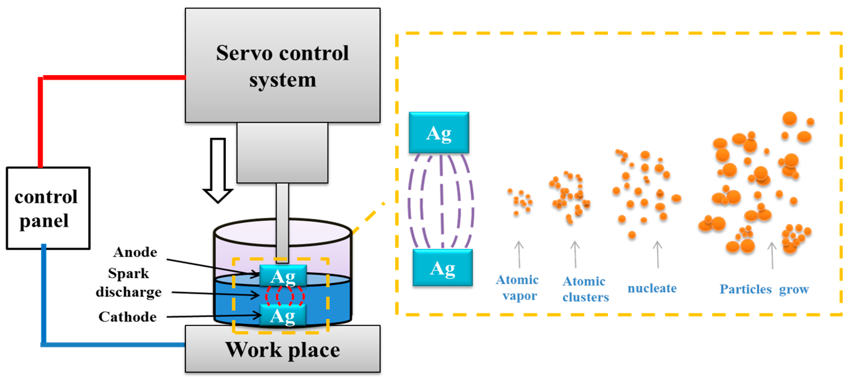
Figure 2.
XRD patterns of Ag and NPS-Ag0 samples.

Figure 3.
(a) SEM and (b) TEM images of the NPS-Ag0, high-resolution TEM images (c,d) of the NPS-Ag0. The stacking faults, amorphous region, grain boundary, and twin defects are indicated.
Figure 3.
(a) SEM and (b) TEM images of the NPS-Ag0, high-resolution TEM images (c,d) of the NPS-Ag0. The stacking faults, amorphous region, grain boundary, and twin defects are indicated.
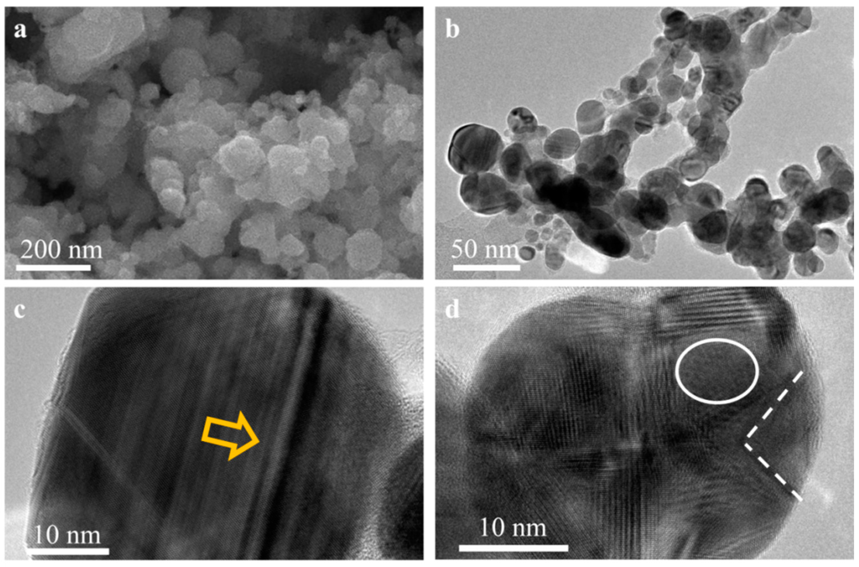
Figure 4.
(a) ORR polarization curves of catalysts in O2-saturated 0.1 M KOH solution at scan rate of 5 mV·s−1 and rotation rate of 1600 rpm. (b) Koutecky–Levich plots at 0.5 V electrode potential (c) Tafel plots from catalysts. (d) Comparison of catalytic activities for ORR of each sample given as the jk,mass and jk,specific.
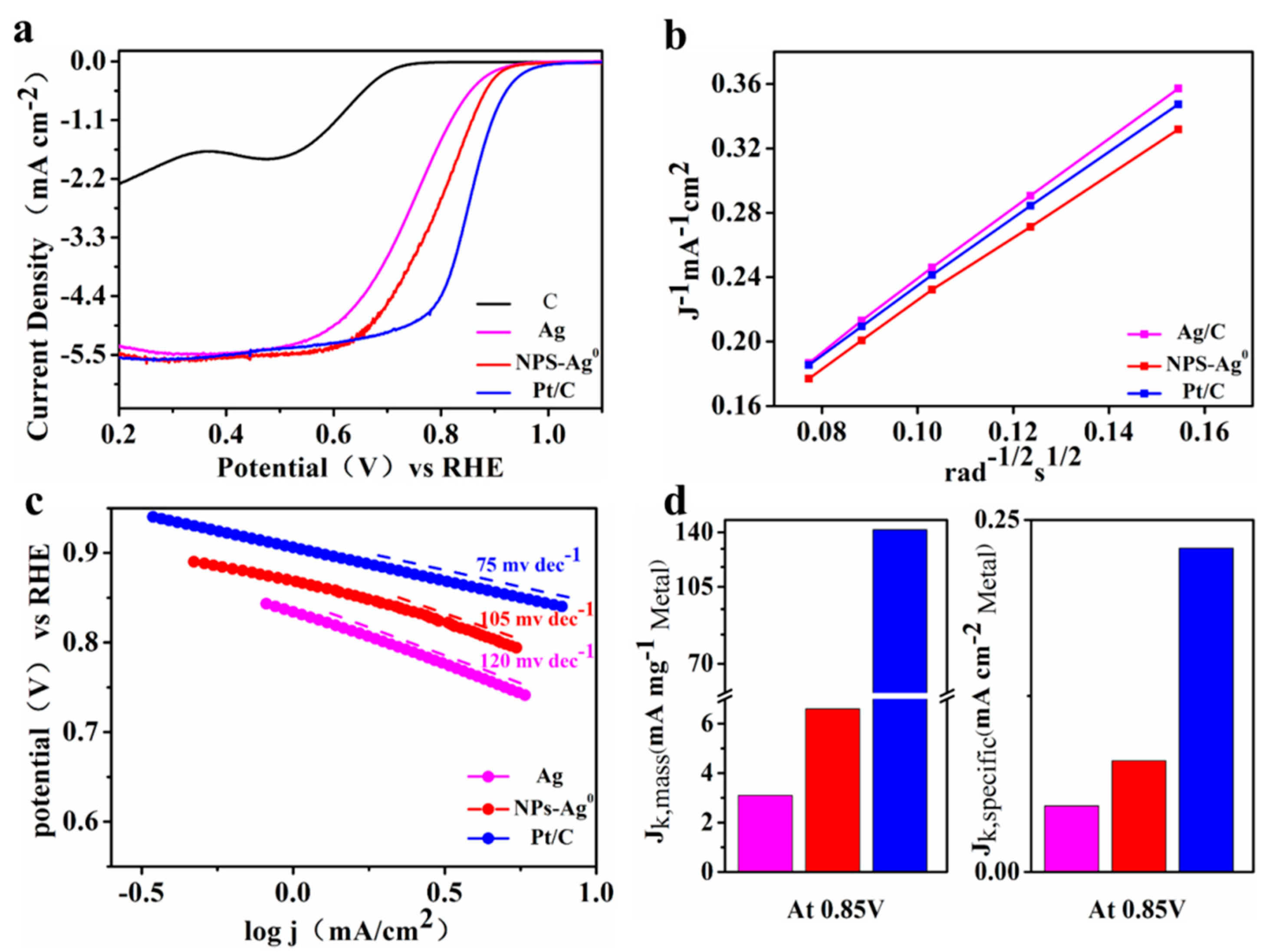
Figure 5.
Chronoamperometric response of the NPS-Ag0, Ag and Pt/C at 0.5 V (percentage of the current retained-operation time).
Figure 5.
Chronoamperometric response of the NPS-Ag0, Ag and Pt/C at 0.5 V (percentage of the current retained-operation time).

Figure 6.
(a) XPS spectra of Ag. (b) XPS spectra of NPS-Ag0. (c) Valence band spectra (VBS) of the Ag and NPS-Ag0.
Figure 6.
(a) XPS spectra of Ag. (b) XPS spectra of NPS-Ag0. (c) Valence band spectra (VBS) of the Ag and NPS-Ag0.

Publisher’s Note: MDPI stays neutral with regard to jurisdictional claims in published maps and institutional affiliations. |
© 2021 by the authors. Licensee MDPI, Basel, Switzerland. This article is an open access article distributed under the terms and conditions of the Creative Commons Attribution (CC BY) license (https://creativecommons.org/licenses/by/4.0/).
Share and Cite
MDPI and ACS Style
Guo, J.; Mu, X.; Song, S.; Ren, Y.; Wang, K.; Lu, Z. Preparation of Ag0 Nanoparticles by EDM Method as Catalysts for Oxygen Reduction. Metals 2021, 11, 1491. https://doi.org/10.3390/met11091491
AMA Style
Guo J, Mu X, Song S, Ren Y, Wang K, Lu Z. Preparation of Ag0 Nanoparticles by EDM Method as Catalysts for Oxygen Reduction. Metals. 2021; 11(9):1491. https://doi.org/10.3390/met11091491
Chicago/Turabian StyleGuo, Jia, Xiaoming Mu, Shihao Song, Yanwei Ren, Kai Wang, and Zunming Lu. 2021. "Preparation of Ag0 Nanoparticles by EDM Method as Catalysts for Oxygen Reduction" Metals 11, no. 9: 1491. https://doi.org/10.3390/met11091491
Note that from the first issue of 2016, this journal uses article numbers instead of page numbers. See further details here.