
Manufacture of Defined Residual Stress Distributions in the Friction-Spinning Process: Investigations and Run-to-Run Predictive Control

Faculty of Mechanical Engineering, Forming and Machining Technology, Paderborn University, 33098 Paderborn, Germany
*
Author to whom correspondence should be addressed.
Metals 2022, 12(1), 158; https://doi.org/10.3390/met12010158
Submission received: 25 November 2021
/
Revised: 25 December 2021
/
Accepted: 12 January 2022
/
Published: 15 January 2022
(This article belongs to the Section Metal Casting, Forming and Heat Treatment)
Abstract
:Friction-spinning as an innovative incremental forming process enables high degrees of deformation in the field of tube and sheet metal forming due to self-induced heat generation in the forming area. The complex thermomechanical conditions generate non-uniform residual stress distributions. In order to specifically adjust these residual stress distributions, the influence of different process parameters on residual stress distributions in flanges formed by the friction-spinning of tubes is investigated using the design of experiments (DoE) method. The feed rate with an effect of −156 MPa/mm is the dominating control parameter for residual stress depth distribution in steel flange forming, whereas the rotation speed of the workpiece with an effect of 18 MPa/mm dominates the gradient of residual stress generation in the aluminium flange-forming process. A run-to-run predictive control system for the specific adjustment of residual stress distributions is proposed and validated. The predictive model provides an initial solution in the form of a parameter set, and the controlled feedback iteratively approaches the target value with new parameter sets recalculated on the basis of the deviation of the previous run. Residual stress measurements are carried out using the hole-drilling method and X-ray diffraction by the cosα-method.
1. Introduction
Friction spinning is an incremental forming process that exploits the synergies of metal spinning, flow forming and friction welding. Metal spinning makes it possible to manufacture axisymmetric hollow parts from sheet metal or tubular workpieces through incremental forming [1]. In this forming process, radial tensile stresses are superimposed by tangential compressive stresses. Flow forming is the forming of axially symmetrical hollow components from tubular workpieces, in which the wall thickness is reduced by compression [2]. Friction welding is a process for joining components through the generation of frictional heat from the relative movement of the components under a normal force [3]. Friction-spinning combines the mechanisms of the above processes through the synergetic use of heat produced by friction and incremental form generation with the help of universal tools that are moved along a defined trajectory.
Promising results in terms of microstructure and the hardness influence on various steel and aluminium alloys were achieved through the integration of the thermomechanical sub-processes into the friction-spinning process [4]. A new, innovative group of complex multifunctional components, such as hollow metallic workpieces with locally graded properties adapted to the requirements, can thus be produced from semi-finished products in tube, profile or sheet metal form. Application areas could include components in the power train (cardan shaft) or suspension (anti-roll bar) considering just automotive applications. The self-induced heating of the components through the process-integrated friction processes not only enables much greater forming, but also permits defined influencing of the mechanical properties and microstructures [4,5,6].
The complex thermomechanical conditions, however, lead to non-uniform residual stress distributions [7]. Residual stresses can be unintentional [8], but can also be purposefully utilised [9,10]. Locally adapted residual stress distributions are thus aimed at improving the quality and functionality of the friction-spun parts, such as by delaying a failure or triggering failure in a defined way. Residual stresses arise due to plastic deformation misfits between different regions [11]. The possible causes of these deformation misfits can be classified as mechanical, thermal and chemical [12]. Residual stresses can be relieved by stress relief heat treatment and plastic deformation [13].
Figure 1 sets out the process of flange forming through the friction spinning of tubes. The process is subdivided into two phases, (a) the pre-friction phase, and; (b) the forming phase. The pre-friction phase provides a rapid heat input into the workpiece, based on friction. This phase ends with the full engagement of the tool and the material, accompanied by the maximum process temperatures. In the following forming phase, the tool switches the forming direction from an axial to a radial movement in order to complete the flange forming.
The temperature profile in the aluminium flange-forming process (in a range of 350–500 °C) results from the feed rate f as a function of the process time t, while the max. process forces F result from the combination of the feed rate f and the rotation speed n [14].
Metallographic investigations show that friction-spinning workpieces have a non-uniform and high depth-dependent degree of deformation and also that grain structure and recrystallisation can be influenced by the process parameters. The aluminium (AW-6060) flanges have a hardness of 40 to 50 HV1 after the forming process. Their hardness can be increased to 80 to 90 HV1 by aging over 14 h at a temperature of 165 °C. [4]
From the process characteristics of the friction-spinning process described, it can be deduced that residual stresses also result in workpieces that are formed by friction spinning. However, residual stress generation and adjustment in the friction-spinning process have not been sufficiently investigated as yet, and the investigations of partly similar processes, such as metal spinning [1,15], shear forming [16], flow forming [17] and incremental sheet metal forming [18], are only comparable to a limited extent with the unique and significantly more complex friction-spinning process. These studies do, however, show that residual stresses can be adjusted by varying the process parameters in forming processes. In general, the targeted adjustment of residual stresses for a large number of forming processes has not been investigated as yet, and the generation of residual stresses is highly process-dependent, which is why it is difficult to find general strategies for this objective in the literature [19]. Hence, this research investigates the generation of residual stresses in the friction-spinning process with the aim of adjusting them in a targeted manner. Through the targeted adjustment of residual stresses, graded component properties can be achieved that are adapted to the load spectrum and ultimately enable a material to achieve its maximum potential, which is also relevant for the idea of lightweight construction.
The adjustment of residual stresses, however, is tied up with process control and innovative process designs [19]. Our approach involves building up a control system by means of model prediction, based on the idea of closed-loop control for metal forming processes [20]. As an underlying basis, this requires a mathematical-empirical model to describe the residual stresses that occur in the friction-spinning process. With the aim of parameter-based residual stress adjustments in the friction-spinning process, use is made of the design of experiments method. This efficient method permits the effects and interactions of the parameters and a corresponding empirical model to be determined. The model describes the correlations for a target variable as a function of the parameters examined. Target variables can be discrete values or the gradient of a residual stress depth distribution, for example. This method can also be extended and implemented in the broad field.
In this project, residual stress measurement is performed by the incremental hole-drilling method as standardised in ASTM E837-20 [21,22]. This method infers the residual stress distributions from the near-surface strains that are released by hole drilling. Due to the characteristics of the friction-spinning process (e.g., a rotating workpiece), residual stresses cannot usually be measured during the process. Other methods for residual stress analysis, such as ESPI or XRD, cannot do this either [23,24]. Another reason is the thermal dependence of the residual stress generation, which makes it necessary to perform the measurement after the workpiece has cooled down, especially in incremental hot-forming processes such as the friction-spinning process [19]. Since it is not possible to measure residual stresses in-process, the control system is designed as a run-to-run process with a hole-drilling measurement performed after each run. The measuring process must be as close as possible to the process in order to reduce the cycle time of a loop. The 3D-DIC method is one approach that can be adopted for residual stress measurements in close proximity to the process [24], and this has been investigated and improved by a temperature compensation method in previous work [25]. In particular, this method can reduce the process time through automation of the measuring process.
Finally, the measurements must also be conducted at a (functionally) irrelevant measuring point but, for developing the run-to-run control, residual stresses are measured at the point to be controlled, since the stresses must be investigated at their origin in the functionally relevant area. In the case of flanges, near-edge areas are defined as functionally irrelevant, as these can be trimmed off in a subsequent process. It should also be borne in mind that the measurement of residual stress depth profiles in near-edge areas is more critical.
2. Materials and Methods
The workpieces (tubular part with a flange, cf. Figure 1) are manufactured with a computer-controlled friction-spinning machine based on a Leifeld Metal Spinning GmbH PLB400 using the widespread materials of 1.0308 structural steel (S235) with a yield strength of ReH = 384 MPa [26] and a heat-treatable (T6) aluminium alloy 3.3206 (6060) with a yield strength of Rp0.2 = 150 MPa [27] (chemical composition listed in Table 1). KXF carbides are used as tool material for steel forming and steel alloy 1.3343 (hardened) for aluminium forming. The aluminium tubes have dimensions of 80 × 40 × 5 mm, and the steel tubes have dimensions of 80 × 40 × 4 mm. The resulting flange radii R and thicknesses sx are a function of the selected process parameters.
The experimental investigations are carried out by employing design of experiment methods in order to exploit the effects and interactions determined for empirical modelling. The process parameters of the factorial design for the steel-forming experiments are shown in Table 2. In this case, the more accurate factorial design is used, because the control system developed is to be demonstrated through the example of steel forming. Fractional factorial design is used for the aluminium forming experiments in order to effectively determine the influences on residual stress generation.
The parameters used for steel forming are the feed rate f and rotation speed n and also the cooling rate vt, which represents quenching. The workpieces are quenched in water after the process at a workpiece temperature of approx. Tmax = 400 °C. Quenching, in terms of high and graded cooling rates, can lead to the generation of residual stresses. In the case of steel, quenching can also lead to residual stresses due to microstructural transformation. The wall thickness reduction is constant with a column sx = 2.5 mm between the supporting tool and the forming tool in the forming phase. The tool angle α is constant at 35°.
Table 3 shows the process parameters of the fractional factorial design for aluminium forming. The influence of the feed rate f, rotation speed n, the wall thickness reduction described by the wall thickness sx, the tool angle α, and the cooling rate vt are investigated. The aluminium workpieces are quenched in water after the process at a temperature of approx. T = 150 °C.
The residual stress depth evaluations are performed according to ASTM E837-20 [21] on the upper side of the flange at a distance of 30 mm from the centre point (cf. Figure 1c). Hole drilling is performed with Vishay RS 200 and 1.6 mm inverted-cone drills. Use is made of Vishay Micro Measurements’ strain-gauge rosettes CEA-06-062UM-120 for steel and CEA-13-062UM-120 for aluminium. Strains are processed with a universal measuring amplifier HBM MX 440 in a three-wire half-bridge circuit with a 120-ohm precision resistor. Residual stresses are calculated with H-Drill 4.0 according to ASTM E837-20 [21].
Residual stress surface distribution measurements were performed by the Institute of Materials Technology, University of Kassel, Germany, by the (cosα-) X-ray-diffraction method. Temperature measurements are carried out with the thermographic measuring system VarioCAM HiRes 640 G, InfraTec GmbH, Dresden, Germany. Hardness measurements are performed with a Nexus 4000, INNOVATEST Deutschland GmbH, Selfkant-Heilder, Germany.
3. Experimental Investigations
3.1. Process Characteristics of Flange Forming by the Friction Spinning of Tubes
For the following investigations into residual stress distributions in flanges formed by friction- spinning of steel and aluminium tubes, the process characteristics are first described with regard to residual stress generation. The force and temperature profiles are thereby investigated as typical causes of residual stresses.
The process forces essentially depend on the frictional forces and the yield stress of the material, whereby the contact area between tool and workpiece and the relative speeds undergo continuous change during the process. Furthermore, the yield stress of the material decreases, on account of the heat induced by friction.
3.1.1. Process Forces in the Steel-Forming Process
The radial force Frad is essentially determined by the feed rate f (cf. Figure 2a). A higher feed rate f = 1.5 mm/s leads to high radial forces Frad of approx. 11 kN, where half the feed rate f leads to a strong decrease in radial forces. In the further forming process, the forces increasingly decline, correlating with a decreasing funnel-shaped workpiece. The axial force Faxial follows the trend of the measured radial forces Frad.
At the transition from the pre-friction phase to the forming-phase, the wall thickness in the inner radius area is at a maximum, because the material is compressed in this area during the pre-friction phase, resulting in the highest forces (cf. Figure 2a). Due to the expansion into the flange shape, the wall thickness of the workpiece decreases progressively, leading to a decrease in the radial force Frad as a result of a decreasing wall thickness reduction. The highest radial forces Frad occur with lower rotation speeds. This is due to the fact that, with the same feed rate and a lower rotation speed, a higher radial distance is covered, i.e., more is formed in the radial direction per rotation, which generally leads to a higher degree of deformation per rotation in the radial direction and therefore to higher radial forces.
The forces in the tangential direction Ftan are not recorded in this process. It can be assumed that these depend essentially on the friction between the tool and the workpiece and, in particular, on their relative speed. In the tangential direction at a constant rotation speed n, the friction velocity in the tangential direction vtan increases as the flange radius R increases (cf. Figure 2b). In addition, the tribological conditions and the decreasing cone shape must also be considered since this leads to a variable contact area (decreasing during the forming phase) and, thereby, also to decreasing process forces.
3.1.2. Stress States during Aluminium and Steel Flange Forming
The stress state in the forming zone results from the process forces F, which are significantly influenced by the deformation resistance of the material and the prevailing friction conditions. Due to the incremental process characteristics, the forming zone varies throughout the entire process.
The radial feed of the tool, which moves the partial forming zone incrementally over the decreasing funnel-shaped workpiece, initially generates a compressive state in the forming zone (cf. Figure 3a), where build-up edges can also be observed in the tangential and radial direction (cf. Figure 3d). This is followed by a radial, bending-like stress state that decreases toward the tangential direction, where shear forming predominates (cf. Figure 3b). This is subsequently overlaid by compression between the tool and the supporting tool, which leads to the introduction of in-plane tensile stresses that decrease with an increasing flange radius R.
Accordingly, the material is shear-formed throughout the process due to the friction between the material and the tool, as a function of the different velocities vtan and vrad. Considering the law of volume constancy and the acting friction environment, the resulting shear deformation is plausible during expansion into the flange shape. The major shear stress, in particular, is directed in the tangential direction, since the tangential velocity vtan dominates (cf. Figure 3e). Significant shear deformation already occurs in the pre-friction phase. With a higher feed rate f (resp. higher vrad), the degree of deformation per rotation increases in the radial direction and decreases in the tangential direction. This has already been investigated in terms of a decreasing twist angle for aluminium forming. It has been shown that the twist angle is less graded in relation to an increasing flange radius R with higher feed rates f. It was also shown that the twist angle undergoes a significantly lower increase with a higher feed rate in the forming phase than with a lower feed rate [14]
An additional investigation was performed to determine the influence of the forming parameters on forming in the tangential and radial direction. An investigation was conducted into how a set of 4 mm holes deform during the flange-forming process. It can be seen that the main forming direction is almost tangential. To determine the influence of the forming parameters on forming in the tangential and radial direction, the angle φ between the main forming direction of the holes and the tangential direction of the flange was measured (cf. Figure 3f). At the higher feed rate f = 2 mm/s at R = 30 mm, the angle φ of the main forming direction of the holes to the tangential direction of the flange is 27° and, with the lower feed rate f = 1 mm/s, the angle is 17° (cf. Figure 3c). This proves that, at a higher feed rate, the forming of an increment is directed more in the radial direction. It can also be seen that, with an increasing flange radius R, forming in the radial direction decreases steadily in relation to the tangential deformation (φ decreasing with an increasing R).
3.1.3. Thermal Profile of Steel Flange Forming
Temperature measurements with a thermographic camera show that the maximum process temperatures in steel flange forming of Tmax = 900 °C do not depend on either the feed rate f in a range of f = 0.5 to 1.5 mm/s or the rotation speed n in a range of n = 700 to 900 rpm (cf. Figure 2c). However, with a lower feed rate f, the material is affected by the process heat for a longer time. With a feed rate of f = 0.5 mm/s, temperatures over T = 700 °C occur for 110 s. The thermographic images show that the maximum process temperatures of 900 °C only occur directly in the forming area. With a feed rate of f = 1.5 mm/s, temperatures over Tmax = 700 °C occur for only 35 s. The influence of the rotation speed n on the maximum temperatures T is negligible.
The heat is dissipated, in particular, by convection on the upper side and by heat conduction into the supporting tool on the rear side, where convection is hindered by the supporting tool. The heat convection depends on the tangential velocity vtan and increases with an increasing flange radius R. After the forming process, when the rotation stops, the heat dissipation conditions change again through reduced convection. This is an indication of a thermal misfit leading to residual stresses. Furthermore, subsequent quenching can influence this process again.
3.1.4. Softening and Recrystallisation in Steel Flange Forming (1.0308)
Hardness measurements are carried out to examine whether residual stresses can arise from martensite microstructural transformations as a result of hardening in the process with the selected process parameters (feed rate and quenching). This occurred with the friction spinning of steel 1.7225, which, however, has a greater aptitude for hardening than steel 1.0308 [28]. Hardness was measured in the tube shaft as a reference and in the flange core at a flange radius of R = 20, 30 and 40 mm (cf. Figure 4). It can be seen that all measured hardness values of the formed flange (130 to 196 HV10) are lower than those of the initial tube shaft (210 HV10). The hardness values tend to decrease with an increasing flange-radius R. A high feed rate f leads to less softening for R = 20 mm, where the material temperature is over 700 °C for 35 s. A low feed rate f and, therefore, an increasing process time t, with an increasing flange-radius R too, lead to more softening (110 s over 700 °C). In the inner flange area (low R), the process has the shortest heating time due to the only short tool contact time. The outer area of the flange (high R), by contrast, is heated from the beginning of the pre-friction phase to the end of the forming phase. This shows that, throughout the entire process, there is no hardening, but rather a softening or recrystallisation. This may also be due to the only short-time occurrence of the maximum process temperatures of 900 °C in the forming zone. Depending on the degree of deformation and the alloy, recrystallisation starts at approx. 700 °C (0.5 Tm) [29], which can be confirmed by previous microstructural investigations on the friction-spinning process [30]. From this, it can be concluded that martensite formation does not occur and, consequently, residual stresses are not caused by microstructural transformation, although this does not exclude the generation of residual stresses by thermal mismatch.
3.1.5. Thermal Stresses
In the friction-spinning process, the thermal expansion of the workpiece is affected by the clamping of the tube shaft, and graded heat conduction is to be expected, as described above. This leads to the question of which stresses arise due to cooling and whether these are different in the radial and tangential directions. In addition, components cool faster on their edges, for example, than on their surfaces. Additionally, different cooling rates must be considered on account of convection on the flange surface. This complex question can be addressed in further investigations, such as with the help of simulations.
3.2. Near-Surface Residual Stress in Flanges Formed by the Friction Spinning of Steel Tubes 1.0308
In the following, the influences of different process parameters (feed rate f, rotation speed n, and cooling rate vt) on near-surface residual stress distributions in flanges formed by the friction spinning of steel tubes (1.0308) are presented. The measurements show maximum compressive residual stresses of σRStan = −500 MPa and maximum tensile residual stresses of σRStan = 300 MPa. With a maximum hardness of 220 HV, these values are plausible (cf. Figure 4). Figure 5 shows the near-surface residual stress distribution over the radius R of the upper flange side measured by the XRD method, averaged over the high and low setting of each process parameter. It must be noted that the individual effects always act collectively.
In the tangential direction, an increasing progression of compressive residual stress to tensile residual stress can be seen with an increasing flange radius R. In the radial direction, the residual stresses σRSrad are mainly compressive over an increasing flange radius R.
It can be seen that the residual stress curve depends on the feed rate f, especially in the tangential direction (cf. Figure 5 left). The increasing progression of compressive residual stress to tensile residual stress σRStan over the increasing flange radius R correlates with the gradient of the velocity vtan (cf. Section 3.1).
The rotation speed n does not influence the residual stresses over the flange radius R (cf. Figure 5 right), which can be explained by the small range of the rotation speed n investigated of between 700 and 900 rpm. Although the influence on the process forces F is noticeable, it is clearly smaller than the influence of the feed rate f.
Quenching (high cooling rate vt) increases the tensile residual stresses in the tangential direction (cf. Figure 5 mid). The process characteristics described in Section 3.1 indicate that the temperature during the process leads to softening rather than to microstructural transformation and that there is not enough heat left after the process to achieve a large effect by quenching.
The increasing progression of compressive residual stress to tensile residual stress σRStan over the increasing flange radius that has been described is to be investigated and partly offset by a constant friction speed in the tangential direction vtan in future investigations. This relationship could also be used to control the residual stress generation over the whole flange by measuring at an irrelevant measuring point.
3.3. Residual Stress Depth Profile in Flanges Formed by the Friction-Spinning of Steel Tubes (1.0308)
Since the temperature and force profile of the friction-spinning process points to complex residual stress depth distributions (cf. Section 3.1), hole-drilling measurements were performed on the upper side of the flange at a distance of R = 30 mm from the centre point. The influence on the residual stress distribution in the surface layer has already been described in Section 3.2, based on the analysis of the corresponding X-ray residual stress measurements. The process characteristics described above indicate that the residual stress depth distribution is also essentially influenced by the non-uniform plastic deformation and sharp thermal gradients.
In line with the above-mentioned near-surface analysis, there are mainly compressive residual stresses in the radial direction and tensile residual stresses in the tangential direction. In the radial direction up to a depth of z = 0.50 mm, compressive residual stresses in a range of σRSrad = 0 MPa to −350 MPa are generated. Tensile residual stresses are present in a range from σRStan = 0 MPa to +350 MPa with an increasing tendency from a depth of z = 0 mm to 1 mm.
In order to characterize the residual stress distribution through the entire flange thickness, hole-drilling measurements were additionally made, starting from the back of the flange into the core. The continuous residual stress depth distribution is shown in Figure 6. Following the already described residual stress depth distribution up to z = 1 mm, the residual stress curve proceeds constantly from z = 1.5 mm to a depth of z = 2.5 mm. Tensile residual stresses of about σRStan = 300 MPa are present in the tangential direction and compressive residual stresses of about σRSrad = −100 MPa in the radial direction.
Using the design of experiments methods (DoE), the following effects and interactions of the forming parameters on the residual stress depth distribution were determined, thus enabling empirical model-building as a basis for a control system for defined residual stress adjustments. In order to illustrate the effects of the process parameters investigated, Figure 7 shows the residual stress depth distribution in the tangential and radial direction averaged over each process parameter; feed rate f, rotation speed n and quenching vt. It must be noted that the individual effects always act collectively, which is why the interactions are also subsequently described.
It can be seen that the residual stress depth distribution is influenced by the feed rate f, in both the tangential and radial direction (cf. Figure 7, left). In the surface area, a high feed rate f leads to more tensile residual stresses in the tangential direction and more compressive residual stresses in the radial direction. This effect reverses with an increasing depth z, at about 0.4 mm. A low feed rate f thus leads to a steeper residual stress distribution than a high feed rate f. In addition, the following descriptions of the effect and the interactions are limited to the boundaries of the parameter range investigated (cf. Section 2).
The influence of the rotation speed n is essentially restricted to the surface area, especially in the radial direction (cf. Figure 7, mid). A low feed rate f leads to more tensile residual stresses in the tangential direction and to more compressive residual stresses in the radial direction.
Quenching leads to only a slight influence on the residual stress distribution near the surface and the core (cf. Figure 7 right). The strongest effect is in the radial direction near the surface; in the tangential direction, the greatest effect is in the core.
Interactions and Effects of the Parameters (1.0308)
In order to describe the interactions and effects of the parameters on the residual stress depth distribution, the gradients of the residual stress curve mRS are calculated on the basis of linear fitting curves for z = 0.05 to 1 mm (cf. Figure 7, left). The calculated interactions and effects of the parameters are shown in Table 4. The average gradient of the radial residual stress depth distribution is 135 MPa/mm and of the tangential residual stress depth distribution is 200 MPa/mm, where the tangential curve is tensile and the radial curve compressive. As described above, the strongest effect in both directions is the feed rate f. Strong interactions exist between the rotation speed n and the feed rate f in both directions and between the rotation speed n and quenching vt in the tangential direction, which are shown in Figure 8. It can be seen that a low gradient for the residual stress depth distribution mRS can be brought about by the combination of a high feed rate f and a low rotation speed n. A higher gradient is obtained by the combination of a low feed rate f and a high rotation speed n (cf. Figure 8a). A high gradient for the residual stress depth distribution in the tangential direction mRStan is achieved by a combination of a low feed rate f and a high rotation speed n. A low gradient for the residual stress depth distribution in the tangential direction mRStan is achieved by a combination of a high feed rate f and a high rotation speed n (cf. Figure 8b). Quenching vt can lead to a higher gradient for the residual stress depth distribution when the rotation speed n is set low. With a high rotation speed, the gradient of the residual stress depth distribution mRS is not affected by quenching (cf. Figure 8c).
3.4. Discussion of Residual-Stress Generation in Steel Flange Forming
Since the degree of deformation is extremely high and the reduction in the feed rate f does not lead to any reduction in the residual stresses, it can be assumed that residual stresses are not significantly reduced by recrystallisation in this process. Moreover, it can be assumed that the influences of the mechanical stresses are greater than those of the thermal stresses. Nevertheless, the quenching has little influence, especially on the surface in the radial direction.
The stress state in the radial direction is firstly dominated by compression and secondly by a bending-like stress state: tension on the upper side and compression on the rear side. Forming with tension on the upper side and compression on the rear side usually creates compressive residual stresses in the upper side and tensile residual stresses in the lower side, which is also the case in this process [11]. The compressive residual stresses are then generated less in the edge area of the flange, since the bending-like stress state decreases, on account of the process characteristics.
The stress state in the tangential direction is dominated by radius-dependent, increasing shear stresses with an amplifying tensile component induced by the wall thickness reduction, which decreases with an increasing flange radius R. In the area of small flange radii (R < 25 mm), tangential shearing is low, because the initial circumference of the formed increment is not or only slightly expanded compared to its circumference in the flange form. In this area, forming is dominated by the wall thickness reduction. Shear stresses then increase as the flange radius increases. This radius-dependent variation of the stress state in the tangential direction leads to a radius-dependent distribution of compressive to tensile residual stresses in this incremental forming process.
In the mid-section of the flange (R = 30 mm), in the radial direction, compressive residual stresses predominate in the surface layer, and tangential tensile residual stresses predominate in the core. With a higher feed rate f (resp. higher vrad), the degree of deformation per rotation increases in the radial direction (cf. Figure 3c). This results in a smoothing of the gradient mRS of the residual stress depth distribution. With the combination of a high feed rate f and a low rotation speed n, the degree of deformation per increment in the radial direction is the highest, which can also be seen with the highest radial forces Frad. This results in an even lower gradient of the residual stress depth distribution mRS. In order to increase the gradient of the residual stress depth distribution, this interaction can be used in an inverse parameter combination, with a low feed rate f and a high rotation speed n (cf. Figure 8b).
With regard to the formation of thermal residual stresses, however, it can be deduced that a thermal misfit occurs, because the heat is dissipated faster on the surface by convection than on the rear side to the supporting tool. After cooling, compressive stresses remain in the surface layer and tensile residual stresses in the core [11]. In the mid-section of the flange (R = 30 mm), the thermally caused residual stresses thus amplify the mechanical induced residual stresses.
With these results, the residual stress depth distribution can be specifically adjusted by the process parameter settings. The effects and interactions described can be used as a polynomial for predicting the residual stress depth distribution, which is employed in Section 4 for the build-up of the run-to-run predictive control.
3.5. Residual Stress Profile in Flanges Formed by the Friction Spinning of Aluminium 6060 Tubes
There is already a preliminary investigation into the near-surface residual stress distribution of aluminium 6060 (T6) flanges formed by the friction spinning of tubes. The residual stress curves are similar to the one described for flange-forming by the friction-spinning of steel tubes in Section 3.2. In the tangential direction, an increasing progression of compressive residual stress to tensile residual stress can be seen with an increasing flange radius R. In the radial direction, the residual stresses σRSrad are mainly compressive over the increasing flange radius R [31].
3.5.1. Residual Stress Depth Distribution in Aluminium
As described previously, with the investigations into steel flanges, the residual stress depth distributions are also analysed for the forming of aluminium flanges with a flange radius of R = 30 mm. In the radial direction, the compressive residual stresses tend to be constant (max. σRSrad = −50 MPa) with a slightly decreasing tendency with depth (up to approx. σRSrad = 0 MPa) and, in the tangential direction, strongly graded tensile residual stresses exist that increase with depth (max. σRStan = 60 MPa). The tangential tensile residual stresses are also greater at the surface (max. σRStan = 60 MPa). In order to characterize the residual stress distribution throughout the entire thickness of the workpiece, hole-drilling measurements were performed, starting from both sides of the flange into the core. The continuous residual stress depth distribution is shown in Figure 9. From z = 1 mm to a depth of z = 2 mm, the tensile residual stresses increase slightly in the tangential direction, while, in the radial direction, the compressive residual stresses decrease until they disappear.
Using the design of experiments (DoE) methods, the following effects and interactions of the forming parameters on the residual stress depth distribution were determined, thus enabling empirical model-building as a basis for a control system for defined residual stress adjustments. The average values of each high and low process parameter (feed rate f, rotation speed n, wall thickness sx, quenching vt and tool angle α), and thereby their effect on the residual stress depth distribution, are therefore shown in Figure 10. It must be noted that the individual effects always act collectively, which is why the interactions are also subsequently described. In addition, the following descriptions of the effect and the interactions are limited to the boundaries of the parameter range investigated (cf. Section 2).
A higher feed rate f increases the level of tangential tensile residual stresses σRStan and also the level of radial compressive residual stresses σRSrad (cf. Figure 10a). By increasing the rotation speed n, more tangential tensile residual stresses are generated at depth, which also reduces the in-depth radial compressive residual stresses (b). This also influences the gradient mRS of the residual stress curve. Quenching the workpiece with water (high vt) after the process (T = 150 °C) results in a slight reduction in the residual compressive stresses in the radial direction (c). The setting of a low wall thickness sx leads to a greater development of compressive residual stresses in the radial direction and to a reduction in tensile residual stresses in the tangential direction (d). Lowering the tool angle α increases the radial compressive residual stresses and reduces the tangential tensile residual stresses (e).
3.5.2. Interactions and Effects of the Parameters (Aluminum 6060)
It can be seen that, although the level of residual stress depth distributions can be adjusted by the main effects, gradation by means of these effects is less effective. For this reason, and especially because the individual effects always act collectively, the interactions of the process parameters determined with the design of experiments (DoE) methods are also detailed in Table 5. The interactions and effects are set out representatively for the residual stresses in z = 0.2 mm and 0.8 mm as well as the gradient mRS of the residual stress depth distribution, in the tangential and radial direction in each case. The gradients of the residual stress curve mRS are calculated on the basis of linear fitting curves for z = 0.05 to 1 mm.
As described above, the strongest effects in z = 0.2 and 0.8 mm in both directions are the feed rate f and the tool angle α, while the rotation speed n, the interaction of the wall thickness sx and the tool angle α affect the gradient mRS of the residual stress depth profile (cf. Table 5). The average gradient of the radial residual stress distribution mRSrad is 11 MPa/mm and the average gradient of the tangential residual stress distribution mRStan is 23 MPa/mm, whereby the tangential distribution is tensile and the radial distribution is compressive.
Setting a high rotation speed n leads to a steeper gradient mRS for the radial compressive residual stress depth distribution, in particular, but also for the tangential tensile residual stress depth distribution. In the radial direction, setting a low tool angle α increases the effect of the rotation speed n, as illustrated in Figure 11a. The effect of the rotation speed n in the radial direction is also amplified by the setting of a higher wall thickness sx (b). Due to these interactions, gradient mRS can be smoothed in the radial direction. With a thicker wall sx, a higher tool angle α leads to a steeper gradient mRS in the radial and tangential direction, while this effect is reversed when the wall sx is less thick (c1), (c2). Quenching (high vt), in both directions, has a higher effect on gradient mRS when the wall thickness is increased.
3.6. Discussion of Residual Stress’ Generation in Aluminium Flange Forming
In contrast to residual stresses in steel flange forming, mechanically induced residual stresses are relieved by recrystallisation in the ongoing aluminium flange-forming process. Firstly, hardness measurements show that the initial hardness of the aluminium alloy 6060 (T6) of 80 HV0.3 is reduced to a hardness of about 60 HV0.3 in the forming process. Furthermore, the temperatures and high degrees of deformation necessary for recrystallisation are present [32]. The highest process temperatures in the range of 350–500 °C result from a low feed rate f due to the longer process time and, therefore, lead to the longest recrystallisation time [14]. This relationship explains the reduction in residual stress in both directions with a longer process time as a result of a low feed rate f. After cooling, compressive stresses remain in the surface layer and tensile residual stresses in the core due to thermal misfit [11]. In the mid-section of the flange that was investigated, the thermally caused residual stresses thus amplify the mechanically induced residual stresses.
The stress states during the forming phase are similar to those described in Figure 3. Compressive and bending components dominate forming in the radial direction. In the tangential direction, forming is dominated by tensile shear stresses. In the axial direction the wall thickness is reduced by compressive stresses, which lead to additional in-plane tensile stresses in the radial and tangential direction.
The near-surface tensile stresses, the shearing and the in-depth compressive stress states are considered to be responsible for the near-surface radially directed compressive residual stresses and the in-depth tangentially directed tensile stresses, respectively, as already described in similar terms for the formation of residual stresses in steel forming in Section 3.4. With a greater wall thickness reduction (lower wall thickness sx) the gradient of the residual stress depth distribution increases, which can be attributed to the reduced thickness itself or to a higher mechanical misfit in forming.
With a higher rotation speed n (resp. higher vtan) the near-surface radial compressive residual stresses decrease, and the in-depth tensile tangential residual stresses increase. Using this effect, the gradation of the residual stress depth profile can be effectively adjusted. The influence of the rotation speed n in the radial direction is amplified by a lower tool angle α. In this context, higher radial forces Frad prevail in the forming phase, which result from higher bending-like forces, since the funnel shape was formed to a lesser extent in the pre-friction phase by a lower tool angle α. A smaller tool angle α therefore offers a larger adjustment range for the residual stress depth profile gradient mRS. This also allows a parameter to be excluded from the model, thus reducing complexity and error-proneness.
The influence of the wall thickness setting can only be used to a limited extent for residual stress adjustment, however, because a required wall thickness must be assumed. This effect is to be investigated in further studies, insofar as several overruns are performed, including with different tool types, such as additional flow forming. With the aim of achieving stronger gradations and also introducing radial tensile and tangential compressive residual stresses, the major influence of the rotation speed n on the gradation of the residual stress curve is to be utilised and investigated in future by having the tool driven too. The major effect of the tool angle prompts an approach whereby this is controlled too in the friction-spinning process.
4. Process Control for Residual Stress Adjustments in Flange Forming
The design of experiments (DoE) method is employed with the aim of achieving parameter-based residual stress adjustments in the friction-spinning process. Using this efficient method, the effects and interactions of the parameters and a corresponding empirical model were determined, as described in Section 3. The empirical model determined can now be applied for predicting residual stress distributions and used as the basis for process control for residual stress adjustment based on the idea of a closed-loop control for metal forming processes [20]. The control process is designed as a run-to-run process because residual stresses cannot be measured in the friction-spinning process due to its process characteristics and the thermal dependence of the residual stress generation (cf. Section 1).
Figure 12 shows the structure of the run-to-run predictive control. The predictive model described by a polynomial is regarded as the core of the control, since this predicts the generation of residual stress at the depth z of the flange formed by the friction-spinning process in a tangential or radial direction or the gradient mRS of the residual stress distribution. By applying an appropriate solver, the predictive model outputs a set of np process parameters xi for the desired residual stress target value σRS,T:
The effects ci and interactions cij are determined by the design of experiments method. It is also intended to determine these by simulation in order to extend the predictive model. The constant c0 describes the average value of the measured residual stress of the design of experiment investigations. Forming is conducted with the process parameters xi,k determined for the calculated target residual stress value σRS,Ck. The forming processes are labelled continuously with the index k. Residual stresses σRS,Mk are measured after the forming process k. The calculation module controls the feedback of the new target value σRS,Ck+1 to the predictive model:
Damping factor λ determines the level of feedback, which can be established experimentally. It is also conceivable for this to be dependent on the distance to the target value. It can also be useful to set damping factor λ in relation to the distance Δ to the target value. Both can be described by a mathematical function. The threshold value γ of the bypass module prevents a return to the predictive model when the desired accuracy has been reached:
Thus, the calculated target value σRS,Ck of the previous run and the corresponding parameters xi,k are applied. The standard deviation of the residual stress measurement can serve as a reference value for the limit value γ.
Due to the great outlay involved in a measurement, it makes sense to temporarily pause the control after a run-in phase and take random measurements in a stable process. The future approach must therefore involve measurements that are conducted closer to the process. For this purpose, the near-process 3D-DIC-HDM approach has already been investigated as a replacement for the costly off-process HDM and will be further improved in future research [25].
Residual Stress Adjustment by Run-to-Run Predictive Control (Steel 1.0308)
Following the description of the structure of run-to-run predictive control, the specific application of run-to-run predictive control on flange-forming by the friction spinning of steel tubes (1.0308) is described. The empirical model, determined by the design of experiments methods (cf. Section 3.3), which is described by the coefficients (cf. Table 3) of a polynomial (cf. Equation (1)), is applied as the basis for the run-to-run predictive control. The model is limited to the boundaries of the parameter range investigated (cf. Section 2). In particular, the parameter-dependent residual stress adjustment targets the extrema of the empirical model, i.e., the setting of large or small residual stress values in the surface layer or in the core of the component, and thus a high or low gradation. These specifications can be satisfied accurately with this approach, since they are already initially incorporated into the model build-up.
Run-to-run predictive control also provides the option of setting intermediate target values, however. Pursuing this aim, the model is expected to make the most inaccurate predictions. The focus at this point is thus placed on investigating the setting of the damping factor λ for the feedback, which will be examined in what follows.
By way of example, the run-to-run predictive control is applied to the tangential residual stress adjustment of steel flanges formed by the friction spinning of steel tubes (1.0308). The residual stress at z = 0.2 and the gradient mRS of the depth distribution are considered. The gradients of the residual stress curve mRS are calculated on the basis of linear fitting curves for z = 0.05 to 1 mm. The parameters incorporated are the rotation speed n, the feed rate f and the quenching vt. The generalised reduced gradient (GRG) solver is used to solve the nonlinear equations of the predictive model. The value range of the parameters is defined for −1 to 1, as listed in Table 2. The coded values are subsequently translated into real parameter values. The value range of quenching vt is defined as an integer and not zero.
The target value of σRStan = 34 MPa at z = 0.2 mm is achieved with a good match in the first run (a), and hence by the predictive model (cf. Figure 13a). The deviation of Δ = −16 MPa is fed back for the new prediction with the different damping factors. The feedback partially improves the already good result in the second run (λ = 0.1, 0.4 and 1), but also slightly increases the deviation in the case of λ = 0.7.
The target gradient of mRStan = 228 MPa/mm is not attained with the first run (b), which can be attributed to the inaccuracy of the predictive model for this target value or the inaccuracy of a single measurement (cf. Figure 13b). The deviation of Δ = +99 MPa/mm is fed back for the new prediction in the second run with the different damping factors. The biggest improvement is achieved with a damping factor of λ = 0.1 (Δ = +13 MPa/mm), and the least improvement is achieved with a damping factor of λ = 0.7.
The run-to-run predictive control provides a promising initial performance in terms of residual stress adjustments. In principle, residual stress adjustments are possible with this approach. The prediction error of the model is corrected by the feedback to the model. The control is more accurate if it feeds back strongly damped values, because one major limiting factor is the deviation of the hole-drilling measurements and, with regard to the gradation, the linear description model of the actual residual stress curve too. Low damping further amplifies the influences of measurement inaccuracies. High damping makes it possible to overcome the inaccuracies of the prediction model. This method has the potential to be applied to other process variants or other forming processes; thus constituting a further strategy for controlling residual stresses, in addition to those strategies that are presented in the literature [19].
Large-scale series of experiments must now be conducted in order to thoroughly validate the function of the run-to-run predictive control. The hole-drilling method used in this investigation is of limited applicability for this purpose, however. A better approach to this is the near-process residual stress measurement with the 3D-DIC hole-drilling method, which reduces the effort and cost of the measurements [25].
To extend the horizon of the predictive model, integration of the simulation of DoE is planned, as is the implementation of machine learning algorithms. In addition, a multivariate prediction is to be developed and integrated in order to regulate target values and the gradient. Furthermore, the run-to-run predictive control will also be set up for aluminium flange manufacture, considering other promising approaches such as a driven tool system and the integration of further flow-forming processes.
5. Conclusions
In this paper, residual stress generation at the surface and in the depth of aluminium and steel flanges formed by the friction-spinning of tubes are investigated on the basis of the process characteristics, including the stress states. It was found that the residual stresses are mainly induced by the mechanical influences, but also by thermal influences. In the case of steel forming (1.0308), it is concluded that residual stresses are not caused by microstructural transformation. Based on the parameter investigations employing the method of design of experiments (DoE), the residual stresses in the surface layer and at a depth can be specifically adjusted by varying the process parameters. The feed rate with an effect of −156 MPa/mm in the radial direction of the flange (compressive residual stresses) and an effect of −159 MPa/mm in the tangential direction (tensile residual stresses) is the dominating control parameter for residual stress depth distribution in steel flange forming. By contrast, the rotation speed of the workpiece with an effect of 18 MPa/mm in the radial direction (compressive residual stresses) and an effect of 10 MPa/mm in the tangential direction (tensile residual stresses) dominates the gradient of residual stress generation in the aluminium flange-forming process. Hence, within the boundaries of the parameter range investigated, the gradient of the radial residual stress depth distribution in steel flanges can be adjusted by 58% of the mean value of 135 MPa/mm by the rotation speed as the main effect, while the gradient of the radial residual stress depth distribution in aluminium flanges can be adjusted by 82% of the mean value of 11 MPa/mm by the feed rate as the main effect.
The effects and interactions determined were used to build a prediction model that was employed for the development of a run-to-run control. With the run-to-run predictive control, the residual stresses were successfully adjusted to the target values. The predictive model provides an initial solution in the form of a parameter set, and the controlled feedback iteratively approaches the target value with new parameter sets recalculated on the basis of the deviation of the previous run. A target value of σRStan = 34 MPa at z = 0.2 mm is readily achieved with a deviation of Δ = 8 MPa. The target gradient of mRStan = 228 MPa/mm is achieved with a deviation of Δ = 13 MPa/mm for a low damping factor with the feedback of λ = 0.1. Since the basic function of this method has been proven, this method can also be applied to other process variants or in other forming processes.
Based on this study, the residual stress distributions are to be adjusted over the entire flange radius by the run-to-run predictive control, with the associated aim of performing measurements at functionally irrelevant measuring points. To extend the horizon of the predictive model, it is planned to integrate a simulation, together with the implementation of machine learning algorithms. In addition, a multivariate prediction is to be developed and implemented in order to control multiple target values. With the aim of setting stronger gradations and also introducing radial tensile and tangential compressive residual stresses into aluminium flanges, the major influence of the rotation speed n on the gradation of the residual stress depth distribution is to be utilised and investigated in future by having the tool driven too. Further investigations will also be carried out into free forming with complex geometries and in situ quenching, which will lead to martensite formation in steel forming.
Author Contributions
Conceptualization, F.D.; methodology, F.D.; investigation, F.D.; writing—original draft preparation, F.D.; writing—review and editing, F.D. and W.H.; supervision, W.H.; funding acquisition, W.H. All authors have read and agreed to the published version of the manuscript.
Funding
This research was funded by German Research Foundation, grant number HO 2356/14-1.
Data Availability Statement
The data presented in this study are available on request from the corresponding author.
Acknowledgments
The authors would like to thank the German Research Foundation (DFG) for funding the research project “HO 2356/14-1”, with the project number 410908773: “Manufacture of defined residual stress in friction assisted spinning and flow forming”. The research work conducted in this project is the basis of the paper.
Conflicts of Interest
The authors declare no conflict of interest.
References
- Music, O.; Allwood, J.M.; Kawai, K. A review of the mechanics of metal spinning. J. Mater. Processing Technol. 2010, 210, 3–23. [Google Scholar] [CrossRef]
- Runge, M. Spinning and Flow forming: Spinning and flow forming technology, product design, equipment, control systems. Verl. Mod. Ind. 1994, 72, 1–70. [Google Scholar]
- Li, W.; Vairis, A.; Preuss, M.; Ma, T. Linear and rotary friction welding review. Int. Mater. Rev. 2016, 61, 71–100. [Google Scholar] [CrossRef]
- Lossen, B.; Andreiev, A.; Stolbchenko, M.; Homberg, W.; Schaper, M. Friction-Spinning—Grain Structure Modification and the Impact on Stress/Strain Behaviour. J. Mater. Processing Technol. 2018, 261, 242–250. [Google Scholar] [CrossRef]
- Lossen, B.; Homberg, W. Friction-spinning—Interesting Approach to Manufacture of Complex Sheet Metal Parts and Tubes. Procedia Eng. 2014, 81, 2379–2384. [Google Scholar] [CrossRef] [Green Version]
- Homberg, W.; Hornjak, D.; Beerwald, C. Manufacturing of Complex Functional Graded Workpieces with the Friction-Spinning Process. Int. J. Mater. Form. 2010, 3, 943–946. [Google Scholar] [CrossRef]
- Schajer, G.S.; Whitehead, P.S. Hole-Drilling Method for Measuring Residual Stresses. Synth. SEM Lect. Exp. Mech. 2018, 1, 1–186. [Google Scholar] [CrossRef]
- Withers, P.J. Residual stress and its role in failure. Rep. Prog. Phys. 2007, 70, 2211–2264. [Google Scholar] [CrossRef] [Green Version]
- Sticchi, M.; Schnubel, D.; Kashaev, N.; Huber, N. Review of Residual Stress Modification Techniques for Extending the Fatigue Life of Metallic Aircraft Components. Appl. Mech. Rev. 2014, 67, 10801. [Google Scholar] [CrossRef]
- Maeder, G. The use of residual stresses in automotive industry. Rev. De Metall.-Cah. D Inf. Tech. 1997, 94, 199. [Google Scholar]
- Withers, P.J.; Bhadeshia, H. Residual stress. Part 1—Measurement techniques. Mater. Sci. Technol. 2001, 17, 355–365. [Google Scholar] [CrossRef]
- Withers, P.J.; Bhadeshia, H. Residual stress. Part 2—Nature and origins. Mater. Sci. Technol. 2001, 17, 366–375. [Google Scholar] [CrossRef]
- Robinson, J.S.; Pirling, T.; Truman, C.E.; Panzner, T. Residual stress relief in the aluminium alloy 7075. Mater. Sci. Technol. 2017, 33, 1765–1775. [Google Scholar] [CrossRef]
- Lossen, B.; Homberg, W. Friction spinning—Twist phenomena and the capability of influencing them. In ESAFORM 2016, Proceedings of the 19th International ESAFORM Conference on Material Forming, Nantes, France, 27–29 April 2016; AIP Publishing LLC: Melville, NY, USA, 2016; p. 70001. [Google Scholar] [CrossRef]
- LI, Z.; SHU, X. Residual stress analysis of multi-pass cold spinning process. Chin. J. Aeronaut. 2021, 35, 259–271. [Google Scholar] [CrossRef]
- Wong, C.; Dean, T.; Lin, J. A review of spinning, shear forming and flow forming processes. Int. J. Mach. Tools Manuf. 2003, 43, 1419–1435. [Google Scholar] [CrossRef]
- Tsivoulas, D.; Da Quinta Fonseca, J.; Tuffs, M.; Preuss, M. Effects of flow forming parameters on the development of residual stresses in Cr-Mo-V steel tubes. Mater. Sci. Eng. A 2015, 624, 193–202. [Google Scholar] [CrossRef]
- Maaß, F.; Hahn, M.; Tekkaya, A.E. Adjusting residual stresses by flexible stress superposition in incremental sheet metal forming. Arch. Appl. Mech. 2021, 91, 3489–3499. [Google Scholar] [CrossRef]
- Franceschi, A.; Stahl, J.; Kock, C.; Selbmann, R.; Ortmann-Ishkina, S.; Jobst, A.; Merklein, M.; Kuhfuß, B.; Bergmann, M.; Behrens, B.-A.; et al. Strategies for residual stress adjustment in bulk metal forming. Arch. Appl. Mech. 2021, 91, 3557–3577. [Google Scholar] [CrossRef]
- Allwood, J.M.; Duncan, S.R.; Cao, J.; Groche, P.; Hirt, G.; Kinsey, B.; Kuboki, T.; Liewald, M.; Sterzing, A.; Tekkaya, A.E. Closed-loop control of product properties in metal forming. CIRP Annals-Manufacturing Technology 2016, 65, 573–596. [Google Scholar] [CrossRef] [Green Version]
- ASTM E837-20. Test Method for Determining Residual Stresses by the Hole-Drilling Strain-Gage Method; ASTM International: West Conshohocken, PA, USA, 2020; Available online: www.astm.org (accessed on 12 February 2021).
- Schajer, G.S. Compact Calibration Data for Hole-Drilling Residual Stress Measurements in Finite-Thickness Specimens. Exp. Mech. 2020, 60, 665–678. [Google Scholar] [CrossRef]
- Fitzpatrick, M.E.; Fry, A.T.; Holdway, P.; Kandil, F.A.; Shackleton, J.; Suominen, L. Determination of Residual Stresses by X-ray Diffraction: Issue 2. Measurement Good Practice Guide; National Physical Laboratory: Teddington, UK, 2005; Volume 52. [Google Scholar]
- Schajer, G.S.; Steinzig, M. Full-Field Calculation of Hole Drilling Residual Stresses from Electronic Speckle Pattern Interferometry Data. Exp. Mech. 2005, 45, 526–532. [Google Scholar] [CrossRef]
- Dahms, F.; Homberg, W. Investigations and Improvements in 3D-DIC Optical Residual Stress Analysis—A New Temperature Compensation Method. In FORMING THE FUTURE: Proceedings of the 13th International Conference on the Technology of Plasticity, Virtual Event (Ohio State University, USA), July 25-30, 2021; Daehn, G., Cao, J., Kinsey, B., Tekkaya, E., Vivek, A., Yoshida, Y., Eds.; Springer International Publishing: Cham, The Netherlands; Volume 21, pp. 2249–2259. ISBN 978-3-030-75380-1.
- DIN EN 10305-1:2016-08. Präzisionsstahlrohre—Technische Lieferbedingungen—Teil1: Nahtlose kaltgezogene Rohre; Deutsche Fassung EN 10305-1:2016; Beuth Verlag GmbH: Berlin, Germany, 2016. [Google Scholar]
- DIN EN 755-2:2016-10. Aluminium und Aluminiumlegierungen—Stranggepresste Stangen, Rohre und Profile—Teil 2: Mechanische Eigenschaften; Deutsche Fassung EN 755-2:2016; Beuth Verlag GmbH: Berlin, Germany, 2016. [Google Scholar]
- Homberg, W.; Lossen, B. Thermal assisted incremental forming of tubes and sheets with process-integrated heat generation: In Functionally Graded Materials in Industrial Mass Production|Volume 2; Heim, H.P., Biermann, D., Homberg, W., Eds.; Verlag Wissenschaftliche Scripten: Auerbach, Germany, 2013; pp. 113–128. ISBN 978-3-942267-91-5. [Google Scholar]
- Doherty, R.D.; Hughes, D.A.; Humphreys, F.J.; Jonas, J.J.; Jensen, D.; Kassner, M.E.; King, W.E.; McNelley, T.R.; McQueen, H.J.; Rollett, A.D. Current issues in recrystallization: A review. Mater. Sci. Eng. A 1997, 238, 219–274. [Google Scholar] [CrossRef] [Green Version]
- Stein, T.; Brueckner-Foit, A.; Lossen, B.; Homberg, W. Fatigue Crack Extension in an Incrementally Formed Tube. In Proceedings of the Procedia Materials Science of 20th European Conference on Fracture, Trondheim, Norway, 30 June–4 July; Volume 3, pp. 1884–1889. [CrossRef] [Green Version]
- Homberg, W.; Hornjak, D. Friction-spinning of tubular components—Basic research on parameter influence and process design. Int. Conf. Technol. Plast. 2011, 10, 548–553. [Google Scholar]
- Lossen, B.; Andreiev, A.; Homberg, W.; Schaper, M. Friction-Spinning—Possibility of Grain Structure Adjustment. Procedia Eng. 2017, 207, 1749–1754. [Google Scholar] [CrossRef]
Figure 1.
Flange forming through the friction spinning of tubes [4]. (a) Pre-friction phase (b) Forming phase (c) Residual-stress measurement.
Figure 1.
Flange forming through the friction spinning of tubes [4]. (a) Pre-friction phase (b) Forming phase (c) Residual-stress measurement.

Figure 2.
Process characteristics of flange forming by the friction spinning of steel (1.0308) tubes as a function of the process parameters rotation speed n and feed rate f. (a) Radial forces, (b) friction velocity, (c) temperature profile.
Figure 2.
Process characteristics of flange forming by the friction spinning of steel (1.0308) tubes as a function of the process parameters rotation speed n and feed rate f. (a) Radial forces, (b) friction velocity, (c) temperature profile.
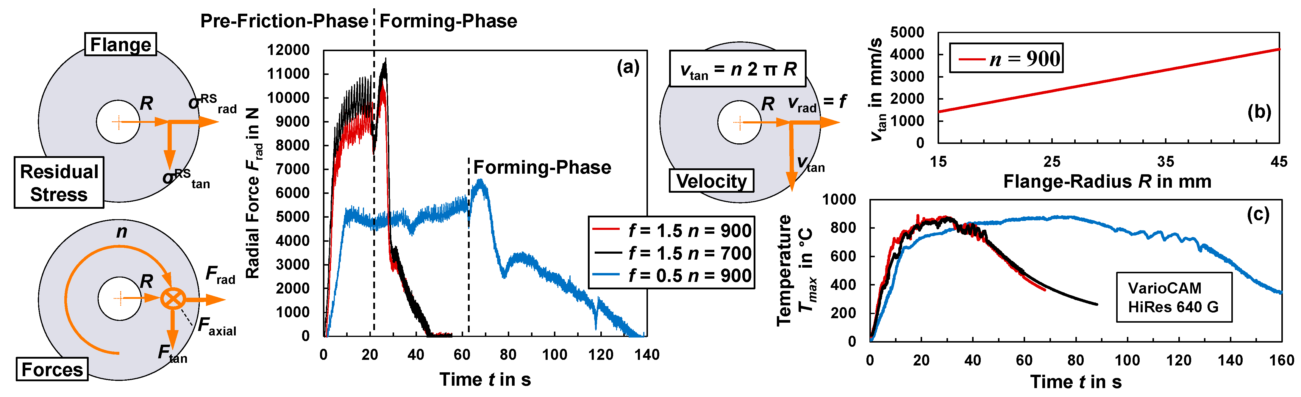
Figure 3.
Stress states in the forming zone during the flange-forming phase in the radial, tangential and axial direction. (a) Stress states in radial direction, (b) stress states in tangential direction, (c) direction of forming, (d) build-up edge, (e) tangential twist, (f) experimental setup main forming direction.

Figure 4.
Hardness measurements in the flange core at R = 20, 30 and 40 mm and the tube shaft as a reference. Flange forming by the friction spinning of steel tubes (1.0308) (D0 = 40 mm, s0 = 4 mm). Quenching is performed after the process with water.
Figure 4.
Hardness measurements in the flange core at R = 20, 30 and 40 mm and the tube shaft as a reference. Flange forming by the friction spinning of steel tubes (1.0308) (D0 = 40 mm, s0 = 4 mm). Quenching is performed after the process with water.

Figure 5.
Near-surface residual stress distributions in steel flanges formed by the friction spinning of tubes (1.0308). Residual stresses measured by the XRD cosα-method on the upper flange side. Values are averaged over the high and low setting of each process parameter.
Figure 5.
Near-surface residual stress distributions in steel flanges formed by the friction spinning of tubes (1.0308). Residual stresses measured by the XRD cosα-method on the upper flange side. Values are averaged over the high and low setting of each process parameter.
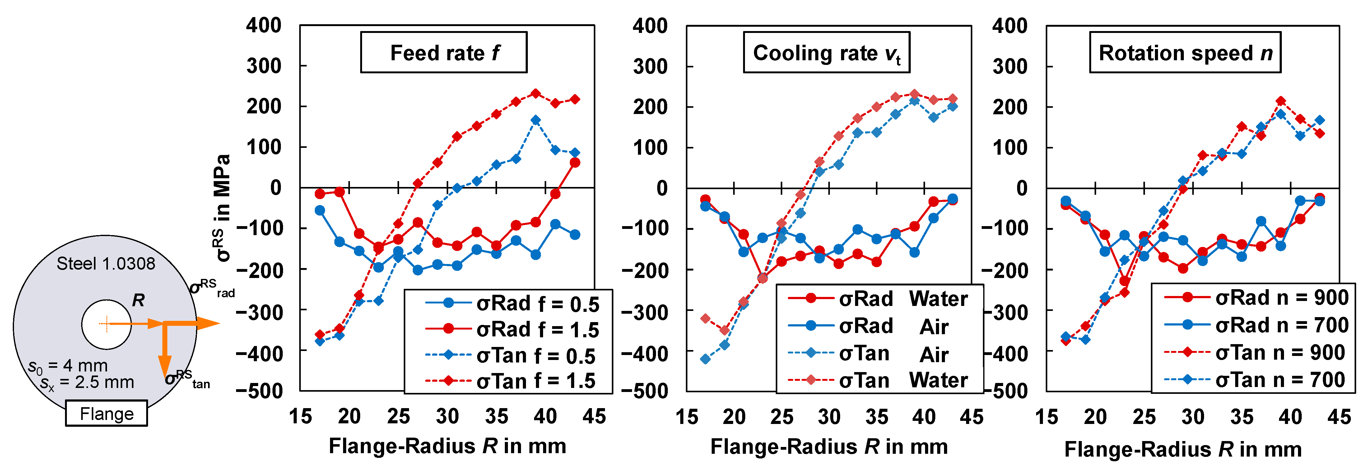
Figure 6.
Continuous residual stress depth distribution. Flange formed by the friction spinning of steel tubes (1.0308). Process parameters: feed rate f = 0.5 mm/s, rotation speed n = 900 rpm, quenching vt performed with water after the process (at Tmax = 400 °C).
Figure 6.
Continuous residual stress depth distribution. Flange formed by the friction spinning of steel tubes (1.0308). Process parameters: feed rate f = 0.5 mm/s, rotation speed n = 900 rpm, quenching vt performed with water after the process (at Tmax = 400 °C).

Figure 7.
Residual stress depth profile in flanges formed by the friction spinning of steel tubes (1.0308) in the tangential and radial direction. Effects of the process parameters determined with the design of experiments methods (DoE): feed rate f, rotation speed n and quenching vt, performed with water after the process at Tmax = 400 °C.

Figure 8.
Effects and interactions, determined with design of experiments methods (DoE), of the feed rate f, rotation speed n and quenching vt on the gradients of the residual stress curves mRS in the tangential and radial direction.
Figure 8.
Effects and interactions, determined with design of experiments methods (DoE), of the feed rate f, rotation speed n and quenching vt on the gradients of the residual stress curves mRS in the tangential and radial direction.

Figure 9.
Continuous residual stress depth distribution. Flange formed by the friction spinning of aluminium tubes (6060). Process parameters: feed rate f = 3 mm/s, rotation speed n = 900 rpm, quenching vt performed with water after the process at T = 150 °C, wall thickness s = 2 and tool angle α = 45 s.

Figure 10.
Residual stress depth profile in flanges formed by the friction-spinning of aluminium tubes (3.0206) in the tangential and radial direction. Effects of the process parameters determined with the design of experiments (DoE) methods: (a) feed rate f, (b) rotation speed n, (c) quenching vt, (d) wall thickness sx and (f) tool angle α.
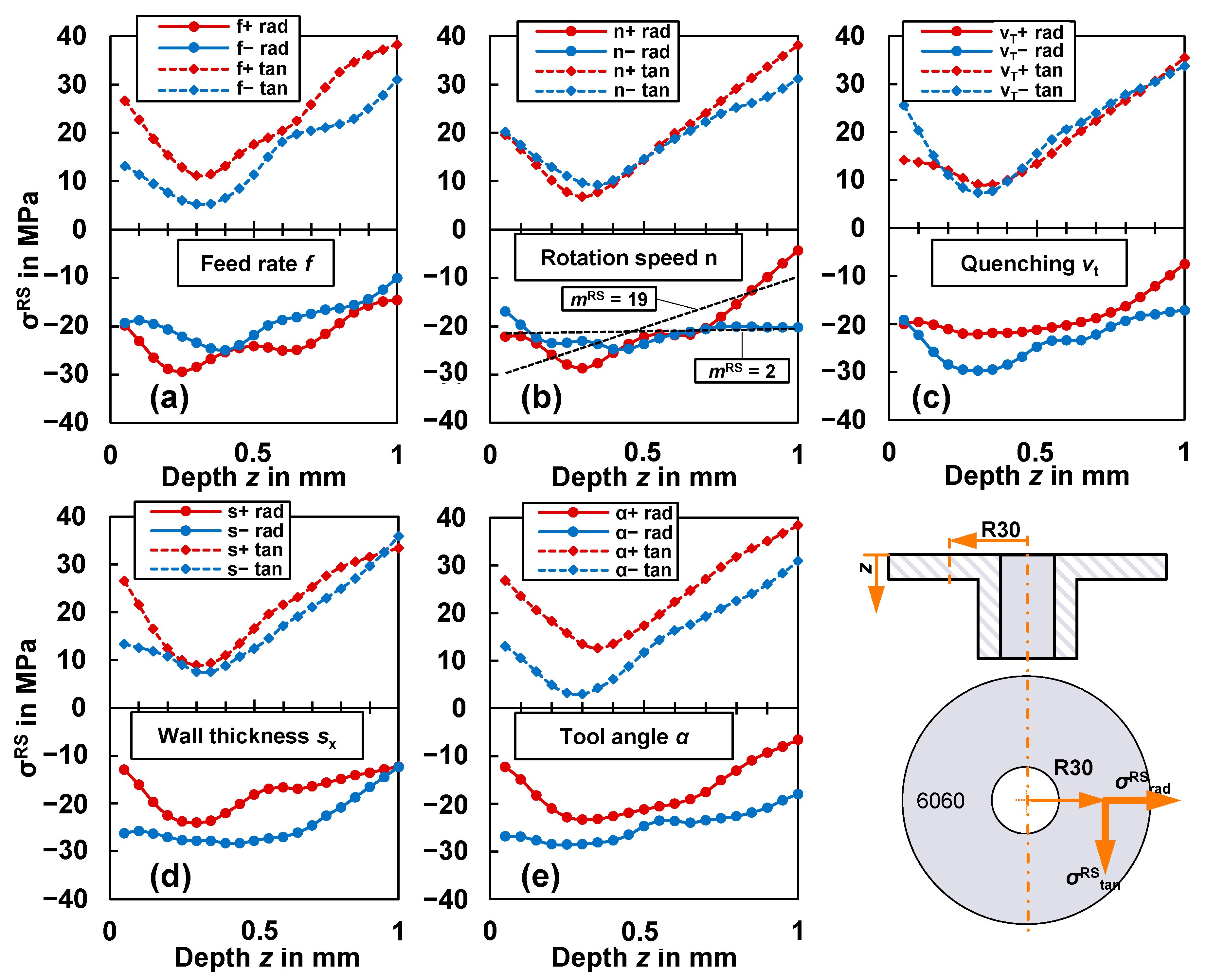
Figure 11.
Effects and interactions of the process parameters, determined with the design of experiments (DoE) methods, tool angle α, rotation speed n, wall thickness sx, quenching vt on the gradient mRS of the residual stress depth profile of aluminum (6060) flanges formed by friction-spinning. Interaction of (a) rotation speed and tool angle, (b) rotation speed and wall thickness, (c1, c2) wall thickness and tool angle, (d1, d2) wall thickness and quenching.
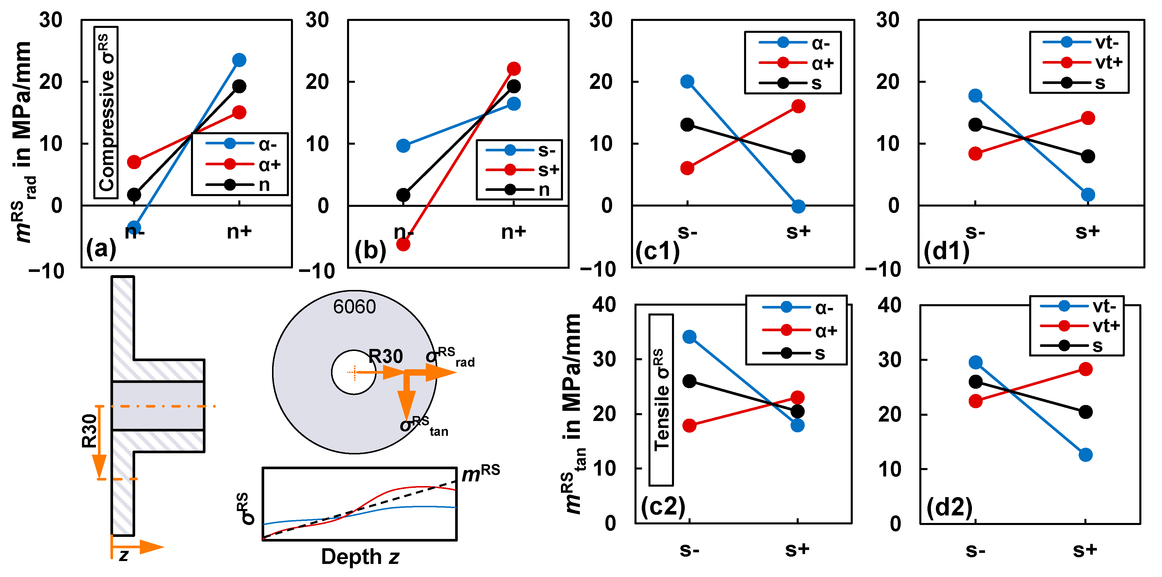
Figure 12.
Run-to-Run Predictive Control.

Figure 13.
Performance of the run-to-run predictive control for two runs with two target values using the damping factors λ = 0.1, 0.4, 0.7 and 1 for the feedback. Flange forming by friction spinning of steel tubes (1.0308). (a) Target value σRStan = 34 MPa at z = 0.2 mm, (b) target value mRStan = 228 MPa/mm.


Table 1.
Chemical composition of aluminium alloy 3.3206 (6060), and 1.0308 structural steel (S235) [26] (wt.%).
Table 1.
Chemical composition of aluminium alloy 3.3206 (6060), and 1.0308 structural steel (S235) [26] (wt.%).
| Alloy | Si | Fe | Cu | Mn | Mg | Cr | Ni | Zn | Ti | Al |
|---|---|---|---|---|---|---|---|---|---|---|
| 6060 | 0.432 | 0.174 | 0.049 | 0.044 | 0.490 | 0.010 | 0.005 | 0.023 | 0.008 | 98.71 |
| Alloy | C | Si | Mn | P | S | Al | ||||
| S235 | 0.17 | 0.35 | 1.20 | 0.025 | 0.025 | 0.015 |
Table 2.
Process parameters for the friction-spinning of steel 1.0308 tubes.
| Parameter Coded | Rotation Speed n [rpm] | Feed Rate f [mm/s] | Quenching vt |
|---|---|---|---|
| +1 | 900 | 1.5 | Water |
| −1 | 700 | 0.5 | Air |
Table 3.
Process parameters for the friction-spinning of aluminium 6060 T6 tubes.
| Parameter Coded | Rotation Speed n [rpm] | Feed Rate f [mm/s] | Quenching vt | Wall Thickness sx [mm] | Tool Angle α [°] |
|---|---|---|---|---|---|
| +1 | 900 | 3 | Water | 2.5 | 55 |
| −1 | 500 | 1.5 | Air | 2 | 45 |
Table 4.
Effects and interactions (DoE) of the parameters (1.0308) on the gradients of the residual stress depth distribution mRS in the tangential and radial direction.
Table 4.
Effects and interactions (DoE) of the parameters (1.0308) on the gradients of the residual stress depth distribution mRS in the tangential and radial direction.
| Residual Stresses | avg. | n | F | vt | n f | n vt | f vt | n f vt | ||
|---|---|---|---|---|---|---|---|---|---|---|
| mRSrad | [MPa/mm] | Grad. | 135 | 65 | −156 | −51 | 31 | −4 | 6 | −48 |
| mRStan | [MPa/mm] | Grad. | 200 | 23 | −159 | 48 | −55 | −35 | −5 | 28 |
Table 5.
Effects and interactions of the process parameters determined with the design of experiments (DoE) methods in z = 0.2 mm, z = 0.8 mm and gradient mRS of the residual stress depth distribution of flanges formed by friction spinning of aluminum (6060) tubes.
Table 5.
Effects and interactions of the process parameters determined with the design of experiments (DoE) methods in z = 0.2 mm, z = 0.8 mm and gradient mRS of the residual stress depth distribution of flanges formed by friction spinning of aluminum (6060) tubes.
| Residual Stresses | z [mm] | avg. | n | f | n f | sx | n sx | f sx | α vt | α | n α | f α | sxvt | sx α | f vt | |
|---|---|---|---|---|---|---|---|---|---|---|---|---|---|---|---|---|
| σRSrad,0.2 | MPa | 0.2 | −25 | −2 | −8 | 1 | 5 | −4 | −1 | −4 | 8 | 2 | −4 | −3 | −3 | −2 |
| σRStan,0.2 | MPa | 0.2 | 12 | −3 | 8 | −4 | 2 | 1 | −1 | 0 | 13 | 1 | 0 | 1 | −5 | 2 |
| σRSrad,0.8 | MPa | 0.8 | −18 | 5 | −3 | −3 | 6 | −1 | 4 | −8 | 10 | −6 | −4 | 2 | 5 | −4 |
| σRStan,0.8 | MPa | 0.8 | 27 | 4 | 11 | −6 | 4 | 0 | 6 | 0 | 9 | 0 | −3 | 6 | 3 | 1 |
| mRSrad | MPa/mm | Grad. | 11 | 18 | 1 | 1 | −5 | 11 | 5 | −7 | 1 | −10 | 3 | 11 | 15 | 0 |
| mRStan | MPa/mm | Grad. | 23 | 10 | −1 | 3 | −6 | 4 | 3 | 3 | −6 | 3 | −3 | 11 | 11 | 7 |
Publisher’s Note: MDPI stays neutral with regard to jurisdictional claims in published maps and institutional affiliations. |
© 2022 by the authors. Licensee MDPI, Basel, Switzerland. This article is an open access article distributed under the terms and conditions of the Creative Commons Attribution (CC BY) license (https://creativecommons.org/licenses/by/4.0/).
Share and Cite
MDPI and ACS Style
Dahms, F.; Homberg, W. Manufacture of Defined Residual Stress Distributions in the Friction-Spinning Process: Investigations and Run-to-Run Predictive Control. Metals 2022, 12, 158. https://doi.org/10.3390/met12010158
AMA Style
Dahms F, Homberg W. Manufacture of Defined Residual Stress Distributions in the Friction-Spinning Process: Investigations and Run-to-Run Predictive Control. Metals. 2022; 12(1):158. https://doi.org/10.3390/met12010158
Chicago/Turabian StyleDahms, Frederik, and Werner Homberg. 2022. "Manufacture of Defined Residual Stress Distributions in the Friction-Spinning Process: Investigations and Run-to-Run Predictive Control" Metals 12, no. 1: 158. https://doi.org/10.3390/met12010158
Note that from the first issue of 2016, this journal uses article numbers instead of page numbers. See further details here.