
Diffusion Bonding of Ti6Al4V at Low Temperature via SMAT
by
Yuqing Chen
1,2, 
Guofeng Wang
1,2,*,
Yongkang Liu
1,2,
Liqiang Zhan
1,2,
He Diao
1,2 and
Yuelin Wang
3 1
Harbin Institute of Technology, School of Materials Science and Engineering, Harbin 150001, China
2
National Key Laboratory for Precision Hot Processing of Metals, Harbin Institute of Technology, Harbin 150001, China
3
Shenyang Aircraft Industry (Group) Co., Ltd., Shenyang 110850, China
*
Author to whom correspondence should be addressed.
Metals 2022, 12(1), 94; https://doi.org/10.3390/met12010094
Submission received: 10 December 2021
/
Revised: 29 December 2021
/
Accepted: 31 December 2021
/
Published: 4 January 2022
(This article belongs to the Special Issue Metal Forming—Hot Forming Technologies of Light Alloy Tubes and Sheets)
Abstract
:Titanium alloys used to be welded to gain good joint strength at 920 °C through diffusion bonding. However, due to the heat preservation at high temperatures for a long time, we obtain joints with great bond strength while the mechanical properties of the sheet are lost. In this paper, taking Ti6Al4V alloy as an example, we studied the microstructure of the surface under the different times of surface mechanical attrition treatment (SMAT). In addition, the microstructure and mechanical properties after diffusion bonding at 800 °C-5 MPa-1 h were also conducted. The results show that the shear strength of TC4 alloy welded joint after SMAT treatment is improved, and the maximum shear strength can reach 797.7 MPa, up about 32.4%
1. Introduction
Titanium alloy is one of the essential metals in the aerospace and military industry. It has a series of advantages such as low density, relatively high specific strength, high specific stiffness, good corrosion resistance, excellent high-temperature service performance, and so on [1,2,3]. It is widely used in the aerospace field, and the usage amount reaches 70% [4]. In the past 50 years, the usage of titanium alloy in military and civil aircraft has been increasing year by year with upgrading their respective products. TC4 titanium alloy is a kind of α + β dual-phase titanium alloy, which is most widely used in the aerospace field, accounting for about 95% of all titanium alloy parts [5,6,7].
However, the high deformation resistance and high heat accumulation of titanium alloy make it difficult to be machined, which hinders the application and development of titanium alloy. A superplastic forming (SPF) and diffusion bonding (DB) process have been proven to be an effective way to fabricate a multilayer integrated structure incorporating these alloys [8,9,10,11]. This method could also reduce the weight of these alloys and the production costs. Han et al. [12] utilized gas pressure control to investigate the SPF/DB of a TC4 alloy honeycomb structure. The study reported that the optimum parameters for the SPF and DB process were 930 °C/0.6 MPa/1 h and 930 °C/10 MPa/0.5 h, respectively. Tan et al. [13] developed a novel SPF/DB method to fabricate a three-layer lattice truss sandwich structure from TC4 alloy at 900 °C/2 MPa/1 h. Zhang et al. [14] studied the diffusion bonding rate and the impact toughness of TC4 alloy joints at different bonding temperatures. The study shows that the 920 °C joints with a high bonding ratio (∼98%) fractured at the base metal during the tensile test showed excellent strength of the joint. However, the impact toughness was 14.99 J/cm2, which is much lower than the 27.3 J/cm2 of the base metal. TC4 titanium alloy can usually get joints with good mechanical properties at more than 900 °C [15,16,17,18], which makes it have problems of a long cycle and high energy consumption in the production and application of large-size parts. Moreover, due to its long-term exposure to high temperatures, the mechanical properties are lost compared with those of the original. Based on satisfying the strength of the titanium alloy, reducing the temperature of diffusion bonding of titanium alloy will significantly improve the production efficiency of diffusion bonding of the titanium alloy.
Due to more grain boundaries, nanomaterials provide more short-range diffusion channels for atomic diffusion, which can significantly improve the diffusion ability of atoms at the interface and inside the material [19,20,21,22,23,24,25]. At present, studies have shown that better diffusion joints can be obtained by shot peening of titanium alloy [26,27], stainless steel [28], and other metals. Still, the traditional shot peening often brings surface damage and local stress concentration in the surface nano process, adversely affecting parts’ subsequent processing. After the nano-treated titanium alloy surface, the surface mechanical attrition treatment has minor wear, roughness, and local stress concentration [29,30,31]. The influence of surface mechanical lapping treatment on diffusion bonding of titanium alloy has not been analyzed deeply. In this work, we conduct experiments on the impact of surface mechanical lapping treatment time on diffusion bonding to determine the optimal SMAT time.
2. Materials and Methods
The original material used in this experiment is a Ti-6Al-4V rolled sheet with a thickness of 2 mm produced by the Baoti Group (Baoji, China). Its main nominal components are shown in Table 1. The sample size is 20 mm × 20 mm × 2 mm, made by electric spark wire cutting, and grind in SiC paper with different P240, P400, P800, P1500, and P2000. The sample had been ultrasonically cleaned in 5%HF +10%HNO3 + H2O solution for 5 min to remove the dense TiO2 film before the SMAT.
SMAT was carried out in a jar with an argon atmosphere using an electromagnetic vibration-assisted setup illustrated in Figure 1. Fix the sample on the upper surface of the pot. The balls used in SMAT are hard alloy steel (YG8, main component is WC) 10 mm in diameter. The frequency of the vibrating platform is 20 Hz, the amplitude of the vibrating platform is 5 mm, and the distance between the specimens and the vibrating platform is 13 mm. The treatment time was 1 h, 2 h, 3 h, and 4 h, respectively. The diffusion connection test was carried out on an electronics universal testing machine (Shimadzu, Kyoto, Japan) equipped with a vacuum high-temperature furnace. The vacuum degree of the equipment was 1.0 × 10⁻³, the diffusion connection temperature was 800 °C, the pressure of the diffusion bonding was 5 MPa, and the time was 1 h.
Some analytical tests were performed to further study the microstructure evaluation at different SMAT times. We employed scanning electron microscopy (SEM, Zeiss Supra55, Jena, Germany) microscopes to study the microstructures. X-ray diffraction (XRD) was taken to test the crystalline phase of the particles using Cu-Kα radiation and 0.02°/s scanning rate on X’Pert Panalytical (Panalytical, Almelo, The Netherlands). We performed Rietveld refinement using the GASA (general structure analysis system) program to obtain the crystal structure parameters.
We evaluated mechanical properties by a shear test performed with a constant compress move rate of 1.0 mm/min at room temperature on a universal testing machine (Shimadzu AGX-Plus, Shimadzu, Kyoto, Japan). Figure 2 shows the specimen size for the shear test.
3. Results and Discussion
3.1. XRD Analysis
XRD analysis, whose test angles ranged from 30° to 80°, was performed on the sample surface at different SMAT times, as shown in Figure 3a. The main content of the TC4 alloy before the SMAT is α-Ti. In the XRD pattern of SMAT-2 h, a new peak can increase to close to 31°, and in the XRD pattern of SMAT-3 h, another peak can increase to close to 36°, and the analysis shows that the peaks represent WC, which is the main component of the steel ball. Compared with the original sample (SMAT-0 h), several prominent peaks of α-Ti after SMAT, such as (101), (002), (102), (103), and (100), all weakened significantly. WC appeared on the sample’s surface after 2 h of SMAT-0 h, and its peak increased with time. Figure 3b is a partial enlargement of Figure 3a from 34° to 42°. It can be seen from the figure that the peaks (101), (002), and (100) of α-Ti gradually widen with the extension of SMAT time.
We obtained the content changes on the surface of samples at different SMAT times after Rietveld refinement, which is shown in Figure 4a. When SMAT was 1 h, WC content on the sample surface was 0.46 wt.%, indicating that WC infiltrated into the surface of TC4 alloy during SMAT treatment. When SMAT time is 2 h, WC content on TC4 alloy surface increases to 3.52 wt.% rapidly. When the SMAT treatment time reaches 3 h, the WC content in the surface of TC4 alloy reaches a maximum of 4.72 wt.%. The content of WC decreased after a prolonged treatment time, which may be related to the shedding of surface metal after amorphous.
Table 2 shows the Full Wave at Half Maximum (FWHM) of α-Ti (101) and its corresponding peak position obtained by finishing the crystal face. We can use the Scherrer Formula (1) to calculate the average grain size of the α-Ti surface layer of TC4 titanium alloy after different SMAT times:
where β represents the diffraction peak broadening value (RAD) caused by grain refinement, and K is the coefficient to be 0.9 when half-height width (FWHM) is used as β to be the broadening; λ represents the incident wavelength of XRD (nm); D is the average grain size (nm). Figure 4b shows the grain sizes corresponding to the half-height width (FWHM) under (101), (002), (102), and (100) crystal planes at different times of SMAT. The average grain size of varying crystal planes was calculated to obtain the average grain size under the SMAT treatment time and was presented by broken lines. With the extension of SMAT treatment time, the grain size of TC4 alloy surface decreases gradually, and the grain size of SMAT treatment for 1 h and 2 h reduces compared with the original grain size. When the SMAT time is 3 h, the average grain size is minimum. The grain size does not change significantly when the time is extended, indicating that the grain is refined to the limit.
The dislocation density of the surface layer of TC4 titanium alloy under different SMAT times can be calculated through the Dunn Formula (2). The dislocation density of each crystal plane satisfies:
where β represents the physical broadening value of diffraction peak (RAD), b represents the Burgess vector (nm), which bTi = 0.289 nm. As shown in Figure 4c, the corresponding dislocation density under (101), (002), (102), and (100) crystal planes at different times of SMAT. The dislocation density on each crystal plane increases after SMAT-1 h and SMAT-2 h, compared with that without SMAT treatment. When the SMAT time is 3 h, the dislocation density of {100} plane and {101} plane increases obviously, which means that, when the SMAT progresses to a certain extent, the proportion of prismatic <a> slip and the first pyramidal <c + a> slip increases, and prismatic slip {100} is dominant. Compared with the SMAT treatment time of 4 h and 3 h, the dislocation density of the basal <a> plane {0002} and crystal plane {102} does not change significantly, but the dislocation density of the prismatic plane {100} and pyramidal plane {101} decreases, which may be related to the amorphous transition on the surface of TC4 alloy. The average dislocation density of the SMAT treatment time was obtained employing the dislocation density of different crystal surfaces and was drawn with broken lines. With the extension of SMAT time, the dislocation density of the TC4 alloy surface increased significantly. Still, when the time reached 4 h, the dislocation density decreased, which was attributed to the surface amorphous transition.
3.2. Microstructure Analysis of Diffusion Bond
SEM analysis was conducted on the microstructure of diffusion bonds of SMAT samples. It can be seen from Figure 5a that cavities can be seen on the interface of diffusion joints without SMAT treatment, and nearly half of the welds are not combined in the area shown. The interface observation of the diffusion joint of SMAT-1 h was shown in Figure 5b. There were still holes on the welding interface, but their proportion was significantly reduced, and the gaps became narrow and long. With the extension of SMAT time, there are apparent heterogeneous components on the interface of the SMAT-2 h diffusion joint, and no central cavity is observed on the welding interface. The welding rate is greatly improved compared with that before treatment. As shown in Figure 5d, when the SMAT time reaches 3 h, the amount of heterogeneous materials on the welding interface increases compared with that at SMAT-2 h. No cavity is observed on the interface. No noticeable difference was observed between SMAT-4 h and SMAT-3 h welding interfaces.
The heterogeneous phase on the diffusion connection interface after SMAT-4 h treatment is shown in Figure 6a. Points 1, 2, and 3 are selected for EDS analysis, and the corresponding results are shown in Figure 6b–d. It can be seen from the figures that the main component of the heterogeneous phase is Ti-Al-W-C-V, and the dominant element is Ti. These heterogeneous phases are mainly due to the reaction between WC, which infiltrated into the surface after SMAT, with TC4 alloy at a high temperature to generate some new phases.
3.3. Analysis of Mechanical Properties of Diffusion Bonds
The shear strength of welded joints can be obtained from compression shear analysis. Figure 7a shows the shear stress–strain curves of diffusion bonds after different SMAT times, and Figure 7b shows the corresponding shear strength of Figure 7a. The stress–strain curve in Figure 7a shows that an apparent yield locus appears when the time of SMAT reaches 3 h. When the joint strength is higher than the yield strength of the base metal itself, the upper end of the shear sample reaches the yield strength, and compression occurs. When the work hardening of the upper end makes the loading strength higher than the shear strength, the joint shear fracture occurs. As shown in Figure 7b, the shear strength of the joint without SMAT treatment is 576.4 MPa after diffusion bonding of 800 °C-5 MPa-1 h. After 1 h diffusion connection of the plate without SMAT treatment, the shear strength of the welded joint increases to 593.8 MPa under the same diffusion connection parameters, an increase of about 3.0%. After 2 h of SMAT treatment, the shear strength of the welded joint is increased to 670.0 MPa with the same diffusion connection parameters by 16.2%. After 3 h of SMAT treatment, the shear strength of the welded joint is increased to 797.7 MPa with the same diffusion connection parameters by 38.4%. Under the same diffusion bonding parameters, the shear strength of the welded joint is 795.3 MPa, which is close to that of the SMAT-3 h.
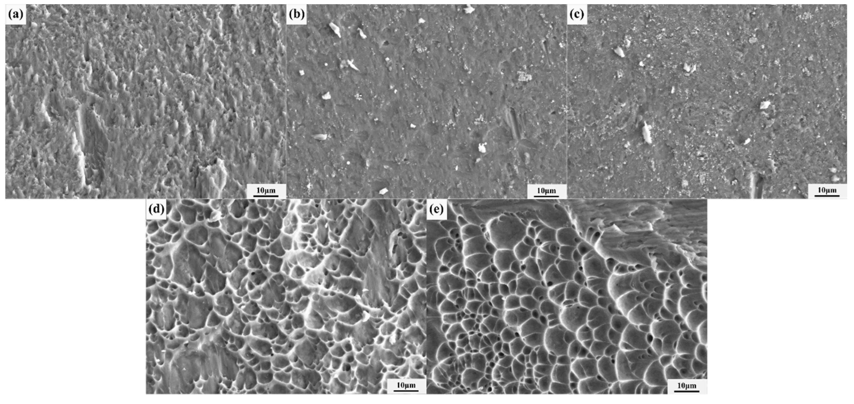
Figure 8 shows the microstructure of the shear fracture of TC4 titanium alloy diffusion joint under different SMAT treatment times. Figure 8a shows the microstructure of the shear fracture of diffusion bonding of TC4 alloy without SMAT treatment. There is no sign of diffusion bonding in some areas, and most measurements show sharp points left after shear fracture, which is a typical brittle fracture. Figure 8b,c respectively show the microstructure of the shear fracture of diffusion joints of TC4 alloy after SMAT-1 h and SMAT-2 h. There are no evident heterogeneous phases on the fracture, which is consistent with the microstructure analysis of the weld. There were many dimples in the rupture of SMAT-2 h, without an apparent unwelded area. Figure 8d,e show the microstructure of the shear fracture of the diffusion joints of TC4 alloy after SMAT-3 h and SMAT-4 h. The fracture mainly presents a large area of dimples. From macroscopic observation, the fracture occurs on the TC4 alloy instead of the welding joint, indicating that the shear strength of the welded joint is higher than that of the base metal itself.
4. Conclusions
In the present work, through the SMAT technique at room temperature, the samples of TC4 alloy were diffusion bonded at 800 °C with high shear strength. The microstructure evolution for the refinement process and the diffusion bonding have been discussed in detail. The main conclusions can be drawn as follows:
1. The severe plastic deformation of SMAT can cause nano-crystallization and amorphous on the surface of TC4 alloy. The XRD calculation shows that the dislocation density increases obviously; the maximum increase is 1008.2%.
2. After SMAT treatment, the strength of TC4 alloy improves after diffusion bonding at 800 °C-5 MPa-1 h. The shear strength of the welding joints of the SMAT-2 h is 670.0 MPa, and that of the SMAT-3 h is 797.7 MPa. Compared with those without SMAT, the shear strength of welded joints increases by 16.2% and 32.4%, respectively.
3. The shear strength of welded joints treated by SMAT for 3 h is higher than the yield strength of base metal TC4 alloy, and the shear fracture occurs on the base metal but not at the weld joint.
Author Contributions
Methodology, Y.C., G.W. and H.D.; validation, Y.C., Y.L., L.Z. and H.D.; formal analysis, Y.C., Y.L. and H.D.; investigation, Y.C., Y.L. and L.Z.; data curation, Y.C. and Y.W.; writing original draft, Y.C.; visualization, Y.C.; conceptualization, G.W.; project administration, G.W. and Y.W.; funding acquisition, G.W.; writing review and editing, G.W. and Y.L.; resources, Y.W.; supervision, Y.W. All authors have read and agreed to the published version of the manuscript.
Funding
This research was funded by the National Natural Science Foundation of China (Grant No. 51875122).
Data Availability Statement
The raw/processed data required to reproduce these findings are available from the corresponding author upon request.
Acknowledgments
This work was also supported by the Special Research on civil aircraft of China: Study on the SPF/DB of the thin-wall titanium alloy at low temperature.
Conflicts of Interest
The authors declare no conflict of interest.
References
- Banerjee, D.; Williams, J.C. Perspectives on titanium science and technology. Acta Mater. 2013, 61, 844–879. [Google Scholar] [CrossRef]
- Wyatt, Z.; Ankem, S. The effect of metastability on room temperature deformation behavior of β and α + β titanium alloys. J. Mater. Sci. 2010, 45, 5022–5031. [Google Scholar] [CrossRef]
- Shen, J.; Sun, Y.; Ning, Y.; Yu, H.; Yao, Z.; Hu, L. Superplasticity induced by the competitive DRX between BCC beta and HCP alpha in Ti-4Al-3V-2Mo-2Fe alloy. Mater. Charact. 2019, 153, 304–317. [Google Scholar] [CrossRef]
- Liu, J. Properties and Applications of Titanium Alloys. Nonferrous Met. Process. 2002, 4, 1–9. [Google Scholar]
- Kashaev, N.; Ventzke, V.; Fomichev, V.; Fomin, F.; Riekehr, S. Effect of Nd:YAG laser beam welding on weld morphology and mechanical properties of Ti–6Al–4V butt joints and T-joints. Opt. Lasers Eng. 2016, 86, 172–180. [Google Scholar] [CrossRef]
- Mironov, S.; Ozerov, M.; Kalinenko, A.; Stepanov, N.; Plekhov, O.; Sikhamov, R.; Ventzke, V.; Kashaev, N.; Salishchev, G.; Semiatin, L.; et al. On the relationship between microstructure and residual stress in laser-shock-peened Ti-6Al-4V. J. Alloys Compd. 2021, 163383. [Google Scholar] [CrossRef]
- Sticchi, M.; Schnubel, D.; Kashaev, N.; Huber, N. Review of Residual Stress Modification Techniques for Extending the Fatigue Life of Metallic Aircraft Components. Appl. Mech. Rev. 2014, 67, 010801. [Google Scholar] [CrossRef]
- Du, Z.; Wang, C.; Liu, Q.; Wang, S.; Liu, Y.; Wang, G. The superplastic forming/diffusion bonding of TA7 titanium alloy for manufacturing hollow structure with stiffeners. J. Manuf. Process. 2021, 73, 385–394. [Google Scholar] [CrossRef]
- Li, X.; Wang, G.; Gu, Y.; Li, D.; Fang, H. Investigation on electrically-assisted diffusion bonding of Ti 2 AlNb alloy sheet by microstructural observation, mechanical tests and heat treatment. Mater. Des. 2018, 157, 351–361. [Google Scholar] [CrossRef]
- Du, Z.; Ma, S.; Han, G.; Wei, X.; Han, J.; Zhang, K. The parameter optimization and mechanical property of the honeycomb structure for Ti2AlNb based alloy. J. Manuf. Process. 2021, 65, 206–213. [Google Scholar] [CrossRef]
- Mikhaylovskaya, A.V.; Mosleh, A.O.; Kotov, A.D.; Kwame, J.S.; Pourcelot, T.; Golovin, I.S.; Portnoy, V.K. Superplastic deformation behavior and microstructure evolution of near-α Ti-Al-Mn alloy. Mater. Sci. Eng. A 2017, 708, 469–477. [Google Scholar] [CrossRef] [Green Version]
- Han, W.; Zhang, K.; Wang, G. Superplastic forming and diffusion bonding for honeycomb structure of Ti–6Al–4V alloy. J. Mater. Process. Technol. 2007, 183, 450–454. [Google Scholar] [CrossRef]
- Tan, Z.; Bai, L.; Bai, B.; Zhao, B.; Li, Z.; Hou, H. Fabrication of lattice truss structures by novel super-plastic forming and diffusion bonding process in a titanium alloy. Mater. Des. 2016, 92, 724–730. [Google Scholar] [CrossRef]
- Zhang, H.; Li, J.; Ma, P.; Xiong, J.; Zhang, F. Study on microstructure and impact toughness of TC4 titanium alloy diffusion bonding joint. Vacuum 2018, 152, 272–277. [Google Scholar] [CrossRef]
- de Salazar, J.G.; Ureña, A.; Carrión, J. Charpy impact test of Ti-6Al-4V joints diffusion welded at low temperature. Scr. Mater. 1996, 35, 479–484. [Google Scholar] [CrossRef]
- Cepeda-Jiménez, C.; Carreño, F.; Ruano, O.; Sarkeeva, A.; Kruglov, A.; Lutfullin, R. Influence of interfacial defects on the impact toughness of solid state diffusion bonded Ti–6Al–4V alloy based multilayer composites. Mater. Sci. Eng. A 2013, 563, 28–35. [Google Scholar] [CrossRef] [Green Version]
- Tuppen, S.J.; Bache, M.R.; Voice, W.E. Structural integrity of diffusion bonds in Ti–6Al–4V processed via low cost route. Mater. Sci. Technol. 2006, 22, 1423–1430. [Google Scholar] [CrossRef]
- Li, H.; Li, M.-Q.; Yu, W.-X.; Liu, H.-B. Significance and interaction of bonding parameters with bonding ratio in press bonding of TC4 alloy. Rare Met. 2014, 35, 235–241. [Google Scholar] [CrossRef]
- Olugbade, T.; Lu, J. Literature review on the mechanical properties of materials after surface mechanical attrition treatment (SMAT). Nano Mater. Sci. 2020, 2, 3–31. [Google Scholar] [CrossRef]
- Lin, Y.; Lu, J.; Wang, L.; Xu, T.; Xue, Q. Surface nanocrystallization by surface mechanical attrition treatment and its effect on structure and properties of plasma nitrided AISI 321 stainless steel. Acta Mater. 2006, 54, 5599–5605. [Google Scholar] [CrossRef]
- Chang, H.-W.; Kelly, P.; Shi, Y.-N.; Zhang, M.-X. Thermal stability of nanocrystallized surface produced by surface mechanical attrition treatment in aluminum alloys. Surf. Coatings Technol. 2012, 206, 3970–3980. [Google Scholar] [CrossRef]
- Sun, Y.; Bailey, R. Improvement in tribocorrosion behavior of 304 stainless steel by surface mechanical attrition treatment. Surf. Coatings Technol. 2014, 253, 284–291. [Google Scholar] [CrossRef]
- Sun, J.; Yao, Q.; Zhang, Y.; Du, X.; Wu, Y.; Tong, W. Simultaneously improving surface mechanical properties and in vitro biocompatibility of pure titanium via surface mechanical attrition treatment combined with low-temperature plasma nitriding. Surf. Coatings Technol. 2017, 309, 382–389. [Google Scholar] [CrossRef]
- Kashaev, N.; Ventzke, V.; Horstmann, M.; Chupakhin, S.; Riekehr, S.; Falck, R.; Maawad, E.; Staron, P.; Schell, N.; Huber, N. Effects of laser shock peening on the microstructure and fatigue crack propagation behavior of thin AA2024 specimens. Int. J. Fatigue 2017, 98, 223–233. [Google Scholar] [CrossRef] [Green Version]
- Prokhorov, A.; Vshivkov, A.; Plekhov, O.; Kashaev, N.; Fomin, F.; Ozerov, M.; Zherebtsov, S. The Effect of LSP on the Structure Evolution and Self-Heating of ARMCO Iron under Cyclic Loading. Metals 2021, 11, 1198. [Google Scholar] [CrossRef]
- Han, J.; Sheng, G.; Zhou, X.; Sun, J. Diffusion Bonding of Titanium Alloy and Stainless Steel with Surface Nanocrystallization. Rare Met. Mater. Eng. 2010, 39, 42–45. [Google Scholar]
- Li, C.; Si, X.; Bian, S.; Dong, Z.; Huang, Y.; Qi, J.; Feng, J.; Cao, J. Diffusion bonding of Ti and Zr at ultra-low temperature via surface nano-crystallization treatment. Mater. Sci. Eng. A 2020, 785, 139413. [Google Scholar] [CrossRef]
- Han, J.; Sheng, G.M.; Zhou, X.L. Diffusion Bonding of Surface Self-nanocrystallized Ti–4Al–2V and 0Cr18Ni9Ti by Means of High Energy Shot Peening. ISIJ Int. 2008, 48, 1238–1245. [Google Scholar] [CrossRef]
- Zhou, L.; Liu, G.; Han, Z.; Lu, K. Grain size effect on wear resistance of a nanostructured AISI52100 steel. Scr. Mater. 2008, 58, 445–448. [Google Scholar] [CrossRef]
- Chamgordani, S.A.; Miresmaeili, R.; Aliofkhazraei, M. Improvement in tribological behavior of commercial pure titanium (CP-Ti) by surface mechanical attrition treatment (SMAT). Tribol. Int. 2018, 119, 744–752. [Google Scholar] [CrossRef]
- Rajabi, M.; Miresmaeili, R.; Aliofkhazraei, M. Hardness and wear behavior of surface mechanical attrition treated titanium. Mater. Res. Express 2019, 6, 065003. [Google Scholar] [CrossRef]
Figure 1.
Schematic diagram of SMAT setup.
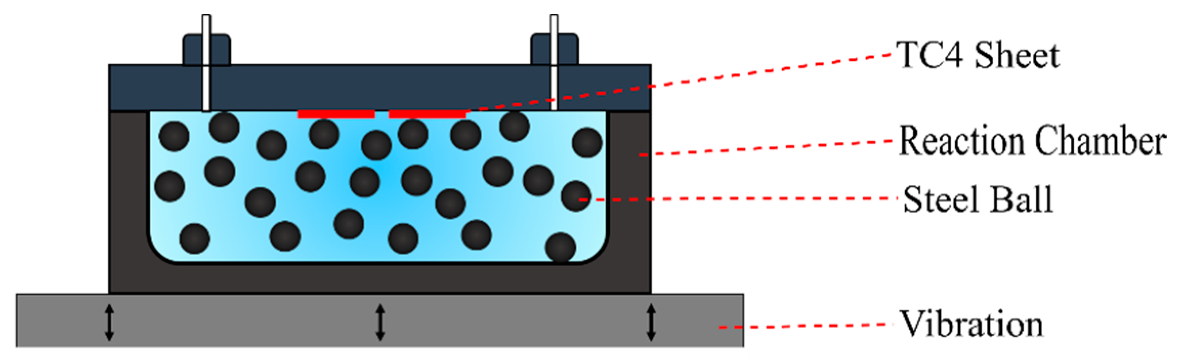
Figure 2.
The specimen size for the shear test, unit: mm
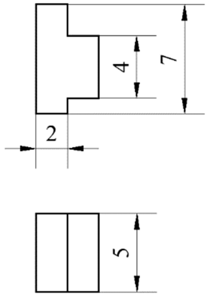
Figure 3.
(a) XRD patterns of the surface of TC4 alloy after different times of SMAT; (b) partial enlargement of (a).
Figure 3.
(a) XRD patterns of the surface of TC4 alloy after different times of SMAT; (b) partial enlargement of (a).
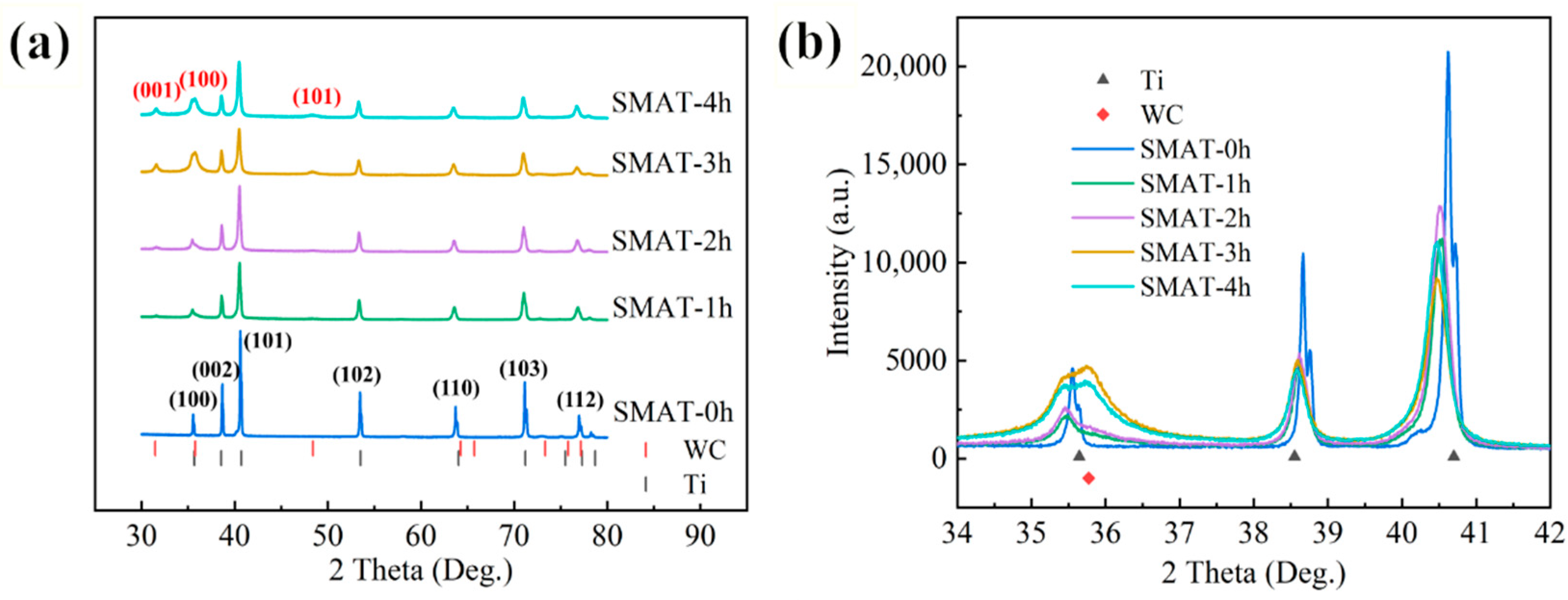
Figure 4.
(a) The content changes on the surface of samples at different SMAT times; (b) the grain sizes under (101), (002), (102), and (100) crystal planes at different times of SMAT; (c) the dislocation density under (101), (002), (102), and (100) crystal planes at different times of SMAT; (d) comparison of grain size and dislocation density.
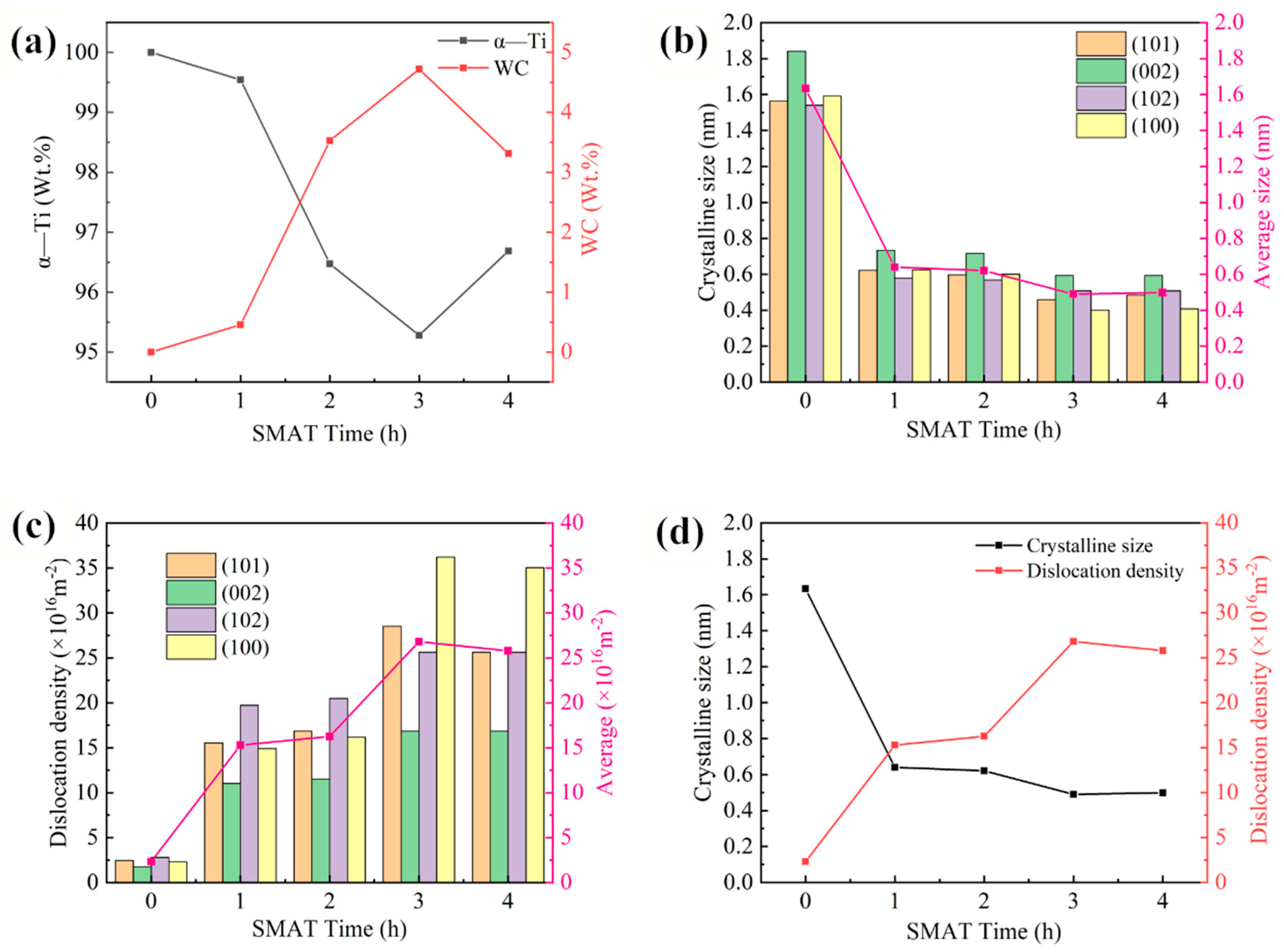
Figure 5.
The microstructure of diffusion bond of SMAT samples: (a) SMAT-0 h; (b) SMAT-1 h; (c) SMAT-2 h; (d) SMAT-3 h; and (e) SMAT-4 h.
Figure 5.
The microstructure of diffusion bond of SMAT samples: (a) SMAT-0 h; (b) SMAT-1 h; (c) SMAT-2 h; (d) SMAT-3 h; and (e) SMAT-4 h.

Figure 6.
(a) The heterogeneous phase on the diffusion bond of the SMAT-4 h TC4 alloy and the enlarged section are inserted; (b–d) are EDS analysis of points 1, 2, and 3, respectively.
Figure 6.
(a) The heterogeneous phase on the diffusion bond of the SMAT-4 h TC4 alloy and the enlarged section are inserted; (b–d) are EDS analysis of points 1, 2, and 3, respectively.
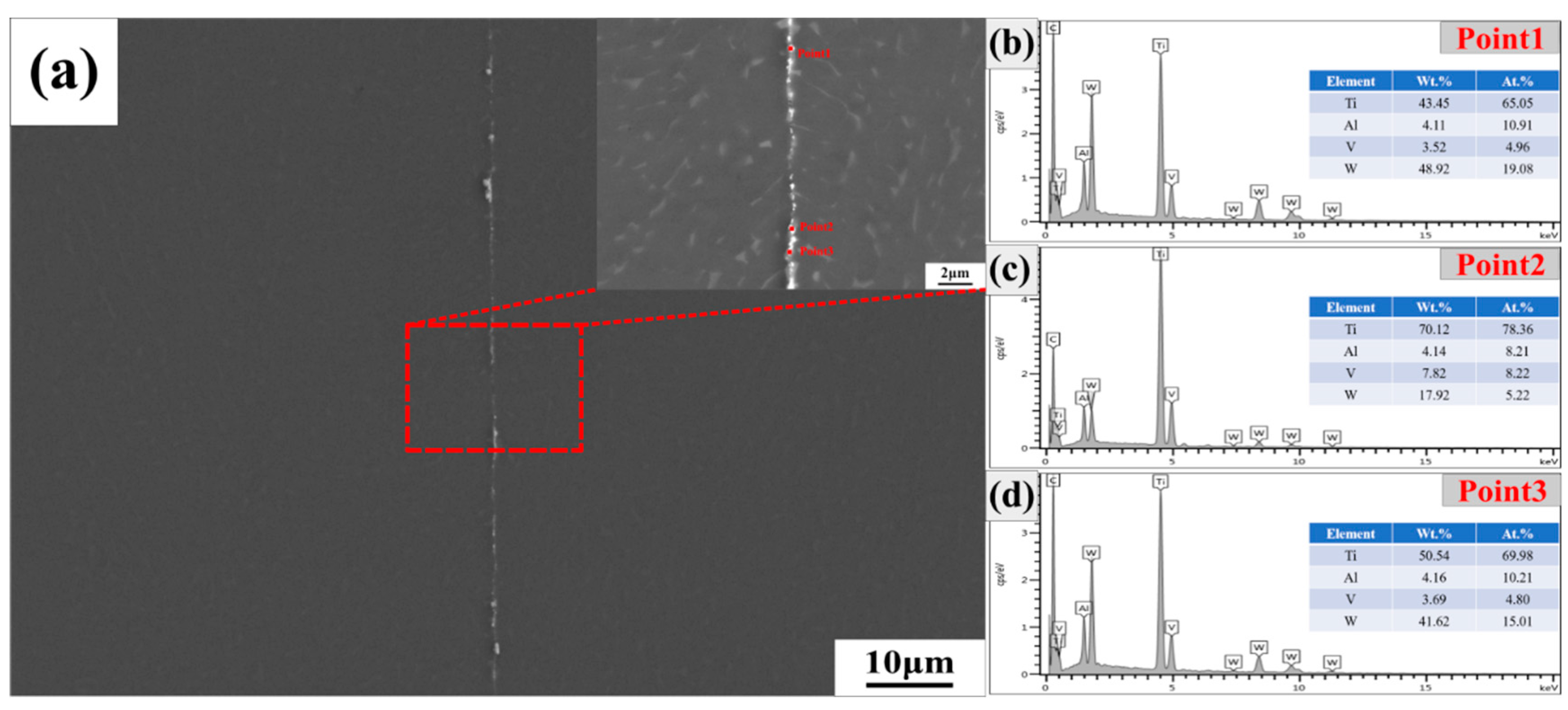
Figure 7.
(a) The shear stress–strain curves of diffusion bond after different SMAT times; (b) the shear strength of diffusion bond after different SAMT times.
Figure 7.
(a) The shear stress–strain curves of diffusion bond after different SMAT times; (b) the shear strength of diffusion bond after different SAMT times.
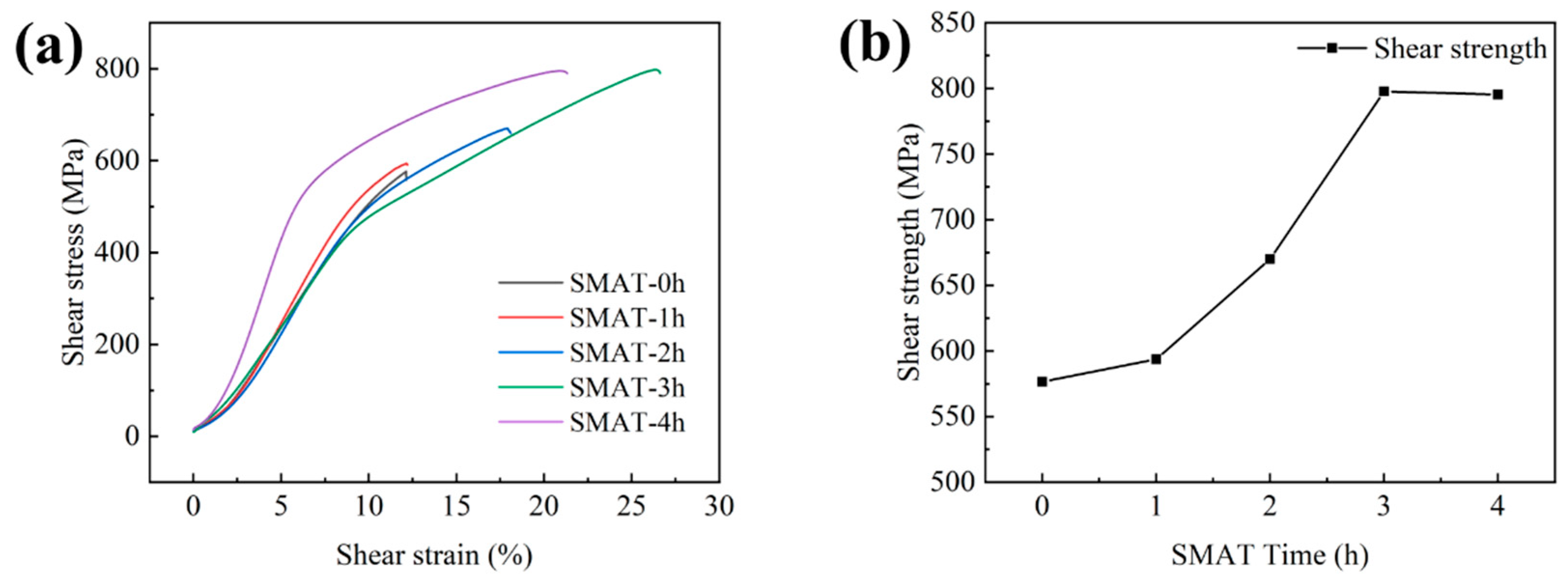
Figure 8.
The microstructure of the shear fracture of TC4 titanium alloy diffusion joint under the different time of SMAT: (a) SMAT-0 h; (b) SMAT-1 h; (c) SMAT-2 h; (d) SMAT-3 h; (e) SMAT-4 h.
Figure 8.
The microstructure of the shear fracture of TC4 titanium alloy diffusion joint under the different time of SMAT: (a) SMAT-0 h; (b) SMAT-1 h; (c) SMAT-2 h; (d) SMAT-3 h; (e) SMAT-4 h.

Table 1.
Chemical composition of TC4 titanium alloy (%, at.).
| Element | Al | V | Fe | C | N | H | O | Ti |
|---|---|---|---|---|---|---|---|---|
| Atom fraction | 5.5~6.8 | 3.5~4.5 | ≤0.50 | ≤0.10 | ≤0.05 | ≤0.015 | ≤0.20 | Bal. |
Table 2.
FWHM and its corresponding peak position of the (101) α-Ti plane.
| (101) | SMAT-0 h | SMAT-1 h | SMAT-2 h | SMAT-3 h | SMAT-4 h |
|---|---|---|---|---|---|
| TTH | 40.6123 | 40.4855 | 40.4791 | 40.4402 | 40.4292 |
| FWHM | 0.0946 | 0.2377 | 0.2475 | 0.3221 | 0.3053 |
Publisher’s Note: MDPI stays neutral with regard to jurisdictional claims in published maps and institutional affiliations. |
© 2022 by the authors. Licensee MDPI, Basel, Switzerland. This article is an open access article distributed under the terms and conditions of the Creative Commons Attribution (CC BY) license (https://creativecommons.org/licenses/by/4.0/).
Share and Cite
MDPI and ACS Style
Chen, Y.; Wang, G.; Liu, Y.; Zhan, L.; Diao, H.; Wang, Y. Diffusion Bonding of Ti6Al4V at Low Temperature via SMAT. Metals 2022, 12, 94. https://doi.org/10.3390/met12010094
AMA Style
Chen Y, Wang G, Liu Y, Zhan L, Diao H, Wang Y. Diffusion Bonding of Ti6Al4V at Low Temperature via SMAT. Metals. 2022; 12(1):94. https://doi.org/10.3390/met12010094
Chicago/Turabian StyleChen, Yuqing, Guofeng Wang, Yongkang Liu, Liqiang Zhan, He Diao, and Yuelin Wang. 2022. "Diffusion Bonding of Ti6Al4V at Low Temperature via SMAT" Metals 12, no. 1: 94. https://doi.org/10.3390/met12010094
Note that from the first issue of 2016, this journal uses article numbers instead of page numbers. See further details here.