Article

Optimization of a Pyrometallurgical Process to Efficiently Recover Valuable Metals from Commercially Used Lithium-Ion Battery Cathode Materials LCO, NCA, NMC622, and LFP

by
Alexandra Holzer
*,
Lukas Wiszniewski
,
Stefan Windisch-Kern
and
Harald Raupenstrauch
Chair of Thermal Processing Technology, Montanuniversitaet Leoben, Franz-Josef-Strasse 18, 8700 Leoben, Austria
*
Author to whom correspondence should be addressed.
Metals 2022, 12(10), 1642; https://doi.org/10.3390/met12101642
Submission received: 21 July 2022 / Revised: 11 September 2022 / Accepted: 27 September 2022 / Published: 29 September 2022

Abstract

:
With an ever-growing demand for critical raw materials for the production of lithium-ion batteries and a price increase of respective commodities, an ever louder call from the industry for efficient recycling technologies can be noticed. So far, state-of-the-art industry-scaled pyrometallurgical recycling technologies all suffer from the same bottleneck of lithium slagging. At the Chair of Thermal Processing Technology at Montanuniversitaet Leoben, a novel reactor was developed to recover lithium and phosphorus via the gas phase in a pyrometallurgical process. Critical elements such as Li, Ni, Co, and Mn of the commercially used cathode materials LCO (LiCoO2), LFP (LiFePO4), NCA (LiNi0.8Co0.15Al0.05O2), and NMC622 (LiNi0.6Mn0.2Co0.2) were analyzed in a batch version of the so-called InduRed reactor concept. The analyses underline that the reactor concept is highly suitable for an efficient recovery for the metals Ni and Co and that slagging of Li can not only be largely prohibited, but the elements lithium and phosphorous can even be recovered from the gas phase. Plant engineering issues were also considered for further development toward a continuous process. The MgO crucible used shows significant diffusion of various elements from the battery material, which is why the choice of crucible material still requires in-depth research.

1. Introduction

With the establishment of a green and low-carbon energy system as a central part of the 2015 Paris Agreement on Climate Change (PA), a limitation of global warming well below 2 °C above preindustrial levels has become international consensus [1]. However, it is commonly criticized that only with much higher efforts than previously anticipated can cited goals be achieved [2]. Next to the energy sector, the transport sector, with approximately 16% of global greenhouse gas (GHG) emissions [3], still takes a lion’s share of the overall 52.4 gigatonnes of CO2 equivalent annually [4]. Furthermore, the quantity of light-duty vehicles is supposed to double by 2050, even increasing the share of emissions within this sector [5]. More efficient technologies have to be introduced to the market to counteract this development and meet the PA’s goals. Electric vehicles (EVs) are one possible solution to cut GHG emissions in this sector [6]. Although EVs have a better CO2 balance than traditional vehicles with internal combustion engines (ICE), there are still parts with huge improvement potential. In particular, the production of the battery itself takes a considerable share of EVs’ overall life cycle emissions, which has already been researched within several studies [6,7,8,9]. Efficient recycling technologies for batteries, and especially for the active material, the so-called black matter–consisting mainly of scrapped anodes and cathodes–could significantly reduce battery life cycle GHG emissions. This can be explained by improved carbon emissions and energy credits compared to sourcing the same raw metals from the respective primary supply chains [10]. Furthermore, since the European Union (EU) is heavily dependent on imports from foreign markets to meet its LIB production resources, the recovery and recycling of valuable metals from spent LIBs is a cornerstone of the EU’s supply independence strategy [11]. To address the sustainable use of these materials, a new proposed regulation amending EU Directive 2006/66/EC and revised version No. 2019/1020, regulating batteries and waste batteries, including recycling efficiency, was published in December 2020 [12]. The proposed regulation stipulates specific material recovery rates, namely 90% for cobalt, copper, and nickel, and 35% for lithium, to be achieved by the end of 2025. By 2030, the recovery levels are further increased, with rates of 95% for cobalt, copper, and nickel, and 70% for lithium [13].
Although several different recycling technologies are already available, ranging from mechanical pre-treatment steps to pyrolysis and metallurgical processes, all face more or less substantial bottlenecks [14]. Mechanical pre-treatment steps, as described in Windisch-Kern et al. [15], are a necessary intermediate step to separate output fractions such as Fe, Cu, and Al from the black matter. This material can then be further processed within hydro-, bio-hydro, or pyrometallurgical processes.
For hydrometallurgical recycling options, the most significant limitation is a fluctuating input material caused by different cell chemistries of used batteries. Hydrometallurgical processes are susceptible to impurities such as fluorine, chlorine, graphite, and especially phosphorus, often either part of the electrolyte or the active material [16]. Additionally, lithium partly remains in the solvent, not being considered for further recovery due to economic considerations [17,18]. Furthermore, conventional hydrometallurgical processes need an extensive amount of acidic reagents, such as HCL, HNO3, and H2SO4, requiring additional disposal or recycling efforts [19]. Despite these limitations, there are already technologies that have excellent recycling efficiencies when only one cathode material is recycled on its own. One possible solution to these harsh chemicals could be ascorbic acid. Researchers have shown that in a two-molar ascorbic acid, NMC cathode material could be recovered with more than 90% efficiency for Li, Co, Ni, and Mn [20]. Another example is the RecycLib process based on hydrometallurgy, which can recycle 80–90% if LCO or NMC cathode material is processed in isolation. In this process, a very mild chemical reagent is also used consisting of magnesium sulfate heptahydrate (MgSO4.7H2O), sodium chloride (NaCl), and deionized water [21]. A more sustainable alternative to traditional hydrometallurgy, however, is bio-hydrometallurgy. One of the most promising processes, bioleaching, requires less energy, is performed at lower temperatures, and has fewer toxic gas emissions [22]. Within bioleaching, microorganisms initiate metal dissolution by using inorganic compounds such as Fe2+, FeS2, etc., as an energy resource, leading to metabolic products, which are a lot less toxic than acids used in hydrometallurgy [23]. However, compared to hydrometallurgical processes, the leaching efficiency is quite low, the leaching time is long due to slow kinetics and pulp densities, and the microorganisms are often complicated to cultivate [24].
Compared to hydro- and bio-hydrometallurgical processes, which operate at lower temperatures, the pyrometallurgical route is performed at high temperatures and, therefore, is mostly insensitive to varying input materials and impurities [25]. However, these processes are likely to face the problem of lithium slagging and metal phosphide formation [26]. Although Li and P are only present in small concentrations compared to the overall battery weight, both elements are found on the EU’s list of critical raw materials with increasing economic value and therefore have to be recycled [27,28]. Next to these technical recycling options, a recycling-oriented design of LIBs, with a more rational design of the module and battery pack itself, easier to handle materials, and a better configuration, could ease the recycling process. Solid-state electrolytes, anode-free cells, or other technical revolutions could move battery technology in a more sustainable direction but have yet to be thoroughly tested [29]. Until these innovations are introduced to the market, a promising solution to these problems is a hydrometallurgical process downstream of a pyrometallurgical process [30]. With the interconnection of efficient pyro- and hydrometallurgical recycling technologies, the advantages of both methods can be used, eliminating most of the disadvantages [31].
Therefore, a novel reactor type was developed at the Chair of Thermal Processing Technology at Montanuniversitaet Leoben to avoid the abovementioned disadvantages in the pyrometallurgical process [32]. The novelty is found in an inductively heated bed of graphite cubes. The black matter is charged continuously via a screw conveyor from above, with the possibility of removing lithium and phosphorus via the gas phase. The main advantage of the reactor concept is the possibility of horizontal and radial homogenous temperature provision, so that an optimum heat transfer to the feedstock can be provided. Furthermore, this reactor design allows the formation of a thin melt film when heated. This, in turn, enormously shortens the diffusion paths compared with, for example, a molten bath [26]. Therefore, undesirable reactions such as iron phosphide formation or lithium slagging are suppressed, and phosphorus and lithium gasification are enabled instead. Therefore, it can be recovered more easily and cost-effectively [33].
Within the scope of this paper, a batch version of this reactor type is analyzed regarding the transfer coefficients of the containing metals from different active materials, not only for lithium and phosphorus, but also for other rare critical raw materials such as nickel, manganese, and cobalt. The influences of plant engineering on recovery rates of lithium via the gas phase are discussed. In particular, the accumulation and diffusion of the elements on and in the MgO crucibles used are examined in more detail. In-depth optimization measures must be taken on the plant design as it evolves into a continuous process. The proposed reactor concept is shown to be well suited for an efficient pyrometallurgical recycling step with considerable improvements in recovery rates compared to today’s BAT technologies.

2. Materials and Methods

As in previous experimental series [26,28], all tests conducted within the scope of this study strictly followed a standardized practical scheme, comprising preparation, experimental procedure, sampling, and analyzing steps. In general, it must be noted that instead of using the continuous InduRed reactor concept, a batch processing lab-scale model with almost identical properties was used. The purpose of this was to ensure comparability to previous test series and a reasonable duration of the trials, resulting in a higher number of experiments at lower costs. The mentioned lab-scale version, the so-called InduMelt reactor, developed at the Chair of Thermal Processing Technology (Montanuniversitaet Leoben, Leoben, Austria), is shown in Figure 1.
The batch version also uses the principle of inductive heating, in which graphite cubes with a side length of 2.5 cm, an electrical resistance of 4–8 µΩm, and a density of 1.55–1.75 gcm−1 are heated. The crucible, which accommodates the graphite bed, is designed as a half-arch bottom with a diameter of 20 cm and a height of 60 cm made of MgO. It is held in position by a structure of refractory concrete and entirely insulated with a high-temperature refractory mat to reduce heat losses. For temperature control, two type S thermocouples were placed on the outer surface of the reactor bottom and another on the reactor wall above the coil. Two additional type K thermocouples were positioned within the graphite bed to realize a more accurate temperature measurement during the heating phase. After the maximum operating temperature of the type K thermocouples (about 1200 °C) was exceeded, the correlation between the inner reactor and outer crucible temperature known from preliminary experiments, the latter measured by the type S thermocouple, was used for the process control.
In this study, the cathode materials LCO, LFP, NCA, and NMC622, each mixed with the corresponding stoichiometrically required amount of carbon for complete reduction, were used as input material for the experiments. The reason why out of several different possible NMC chemistries only NMC622 was analyzed can be explained by today’s and forecasted shares of this cathode material. In most scenarios, the NMC622 cathode chemistry takes the most significant share of up to 90% of all batteries used in electric vehicles in 2030 [34]. During preparation, a sample mass of approximately 550 g was put in the graphite bed’s void fraction in each experiment. The composition of said samples can be seen in Table 1.
The setup, test execution, and sampling were carried out in all tests according to a specified and uniform plan. It should be mentioned that the components were weighed in all the steps explained below during setup and dismantling. At the beginning, the layered loading of the MgO crucible of cubes and the individual sample material, as shown in Table 1, was performed. Two type K thermocouples were incorporated into these layers in the crucible center at different heights to ensure adequate process control in the lower temperature range up to approximately 1200 °C. For the subsequent insulation, an exhaust gas pipe made of Al2O3 was incorporated centrally in the lid insulation to be able to direct the gas produced during operation specifically into the gas extraction hood. After positioning the insulated crucible on the refractory concrete in the coil, one type S thermocouple each was mounted centrally on the reactor floor and one above the coil on the crucible wall. The aim is also to control the temperature above the measuring range of the type K thermocouples using known process values from preliminary tests.
Finally, the temperature was recorded during the experiments via LabVIEW with a parallel recording of the induced power data. To counteract overstressing of the crucible material due to excessive heating rates, a maximum temperature increase of 250 K/h over the experimental period of 7.5 h was selected. With a holding time of half an hour at the end of the tests, a uniform temperature of 1550 °C over the entire reactor was aimed for to always exceed the corresponding melting points of the metals contained. After the experiments, the setup was cooled for at least 24 h and consequently dismantled and unpacked in reverse order to the setup.
The experimental procedure is followed by a standardized sampling and analyzing scheme. Certain product phases, e.g., a slag or a metal alloy, were separated, weighed, and individually analyzed using ICP-OES according to ÖNORM EN ISO 11885:200911. This is performed by manually removing metal and slag depositions from the graphite cubes and the MgO crucible with subsequent magnetic separation. A fine powder phase formed due to abrasion during the removal was also sampled and analyzed separately.
Regarding the evaluation of the gas phase, an exhaust bell was positioned over the exhaust pipe, and a partial off-gas stream was passed over gas scrubbers containing a 2.5-molar H2SO4. To determine the actual presence of lithium or phosphorus in the exhaust stream, thus proving that a gaseous removal was achieved, said gas scrubbing medium was also analyzed using ICP-OES. All analysis results combined with the weighted samples were then used to investigate transfer coefficients of the metals of interest into the respective product phase, thus either the slag, metal, powder, or gas phase.
For a more precise statement of the results, each sample was tested at least twice. For a more straightforward assignment of the individual experiments, the respective cathode material and a consecutive numbering were used as nomenclature. For example, “LCO V1” means experiment one with a mixture of LCO with the respective carbon content from Table 1.
Regarding limitations of the overall process, the temperature is one crucial part that must be considered. Due to the thermal stability of the heating insulation material, temperatures above 1700 °C should not be exceeded. Another limitation for the batch version InduMelt is the limited power supply of 10 kW at maximum. However, for these trials, the heating rate was sufficient to prove that, at the temperature of 1550 °C, high rates of Li or P were transferred into the gas phase, which therefore proved the suitability of the reactor’s core principle.

3. Results and Discussion

3.1. InduMelt Experiments

The main focus of this series of tests was to determine the quality of products that are generated during carbo-thermal reduction of the cathode materials LCO, LFP, NCA, and NMC622. In addition, attention was paid to the influence of plant engineering components on the lithium yield. A total of five fractions were identified as the resulting product streams:
  • “Slag”: Defined as a non-magnetic mineral phase with a grain size greater than 1 mm.
  • “Powder”: Particles smaller than 1 mm and categorized as close to non-magnetic.
  • “Metal fraction”: Defined as a magnetic alloy with a grain size larger than 1 mm.
  • “Magnetic powder”: Particles smaller than 1 mm obtained during magnetic separation.
  • “Gas phase”: Defined as the exhaust gas stream passed through the gas scrubber.
The product properties are discussed in detail in the following subsections to finally realize a comparison of all cathode materials. After the conducted series of experiments, a significant influence on the product quality could be established concerning interrupted gas stream out of the reactor due to a clogged gas pipe. In addition, it was found that the mass balance closure is not possible, mainly due to the difficulty of separating the fractions. Thus, only a qualitative consideration of the results is possible. The choice of reactor material of MgO has been found to significantly impact the transfer coefficient, which is further discussed.

3.1.1. Product Properties of LCO after the Experiments within the InduMelt Reactor

The series of tests started with experiments with LCO, with a total of two tests being carried out. Figure 2 shows examples of the resulting slag, metal, and powder.
Table 2 lists both the masses of the initial input and the fractions obtained. On the one hand, it is noticeable that no sparse magnetic powder was formed and that the proportion of slag, with 0.5% and 0.8% of the total product mass, is vanishingly small compared with the magnetic fractions. Looking at the magnetic fractions, it can be seen that the transfer to the metal fraction was lower by mass in the second experiment.
Analyses of these three products in ICP-OES allowed the chemical composition to be determined, as shown in Table 3. It should be noted that a complete detection rate is not possible for several reasons. Firstly, in addition to the added carbon, the initial composition also contains oxygen from the lithium metal oxide, which cannot be measured via ICP. In addition, the measurement is subject to particular measurement uncertainty. The third factor is sampling. Since the fractions cannot be completely separated from each other without doubt due to their appearance, there is always a certain degree of mixing, which significantly influences the results. The phenomena mentioned must also be considered in this paper’s subsequent experiments. Nevertheless, trends can be identified, allowing a statement to be made about the process.
On closer inspection and direct comparison between the two tests, it can be seen that there are significant differences in product quality. The proportion of lithium in the slag is almost three times higher in the second test. If the mass ratios in Table 2 are also considered, a higher mass proportion is recorded in the second experiment as well. However, since the proportion of slag is negligible, as already mentioned, this fact should not be overestimated. Another interesting finding is that the amount of Co in LCO V2 is lower in the metal but higher in the powder. This is also reflected in the comparison of the masses in Table 2. If the results from Table 2 and Table 3 are summarized, the goal of reducing the metal oxide was basically achieved in both experiments. Even if in the second test the output into the metal fraction did not succeed to such an extent as in the first trial, the high metal content, and the quality, of the increased metal powder content again compensates for the result. However, in terms of simpler and more efficient post-treatment of the products from the InduMelt process, transfer to a metal fraction is preferable. In this application, an acceptable quality of the metal could be found. Maximizing the yield of a metal fraction should be strived for and can be considered an allowable conclusion for the above findings.
By including the results of the off-gas analysis in the interpretation of the results, as shown in Table 4, it can be seen that the lithium extraction amount of 1230 mg/L in the first test is higher than that of the second with 860 mg/L. If we now compare the removal of Li from the metal and powder with the result from the off-gas scrubber, no connection between the increased removal rate in the off-gas with an improved removal of Li in the chemical analysis can be seen.

3.1.2. Product Properties of LFP after the Experiments within the InduMelt Reactor

In investigating the cathode material LFP, two tests were carried out in the InduMelt plant. In addition to slag and metal, both magnetic and non-magnetic powder were recovered from the reactor after the trials. Examples of the appearance of these fractions are illustrated in Figure 3.
The masses of the products and the input material of the two tests can be taken from Table 5. If the masses of the two tests are compared with each other, it can be seen that in LFP V2 the proportion of metal is higher and that of slag is lower. Even if this fact indicates that the efforts towards the higher output of a metal fraction for post-treatment have been successful, the higher proportion of metal powder must be considered in more detail.
If the chemical composition analyses from Table 6 are included in the interpretation, the picture is entirely different from that assumed after evaluating the results with LCO. Li, Fe, and P input into the slag are many times higher in the second test than in the first, and increased values can also be found in the sparsely magnetic powder. High iron and low phosphorus content are particularly desirable in the metal fraction. This requirement is better achieved in the first test. The results in the magnetic powder also speak for the statement to be made here that the second trial, despite a better appearance of the mass ratios, delivers poorer outcomes in the product quality. Therefore, the lower P and higher Fe content in the first test are the decisive values.
Looking at the analyses of the gas fraction in Table 7, it is clear that the yield of Li and P in the second trial is many times higher than in the first trial. The experiments with LFP can be summarized as follows: Either a larger fraction with lower metal quality but a higher yield of Li and P is recovered via the gas stream or a smaller fraction with opposite properties to the former. A comparison of the results of the trials with LCO and LFP is difficult to perform, since the two differ fundamentally in their structural makeup. While LCO, NCA, and NMC are layered oxides, LFP is built up as a three-dimensional olivine structure [35,36].

3.1.3. Product Properties of NCA after the Experiments within the InduMelt Reactor

The cathode material NCA has been tested a total of three times in this described InduMelt setup. After reviewing the first two tests, it was found that the results of the lithium extracted via the gas stream were far below the expected values in both cases. Consequently, a third attempt was carried out. Figure 4 again shows illustrative examples of the fractions obtained: slag, metal, powder with low magnetic content, and magnetic powder.
The masses of the individual fractions in Table 8 show similar ratios. However, at least a small proportion of slag was recovered in the third test, while none was found in the other two. From this representation, it is difficult to estimate the success of the experiments.
The analysis results shown in Table 9 provide a better insight into product quality. Particularly noteworthy is the third test, with its high Ni rates in the metal and powder phase and, compared with the other tests, lower values of Li in the fractions, except the slag. Although the presence of slag is not desirable, the low mass in Table 8 of only 1 g means that this fact should not be overestimated. If only the first two tests are compared, a similar composition can be seen, especially in the metal and powder fractions.
The above findings are also supported by the analyses of the gas flow, which can be seen in Table 10. Thus, an identical amount of 65 mg/L Li was detected in the wash water in the first two tests. The good result of the solid fractions in the third test can also be confirmed by the high Li content of 960 mg/L. In this series of experiments, a positive effect on product quality and yield of Li from the solid fraction can be observed with increased transfer to the wash water.

3.1.4. Product Properties of NMC622 after the Experiments within the InduMelt Reactor

Three tests were carried out with NMC622. Here, similar to the test series with NCA, the wash water analysis of the exhaust gas stream was also far below that expected in the first two trials. The four fractions obtained, slag, metal, barely magnetic powder, and magnetic powder, are exemplified in Figure 5.
In terms of the mass ratios in Table 11, NMC622 V3 with a higher metal and lower powder content than the other two trials, is worth highlighting. The higher proportion of barely magnetic powder or the presence of slag can be classified as more negative. As with the other test series comments, the significance of this weight in terms of test evaluation is subordinate.
However, the results of the chemical analysis given in Table 12 allow the conclusion that NMC622 V3 was more successful than the other two in terms of the product quality obtained. NMC622 V3 is convincing, with higher values for Co, Ni, and Mn, as well as lower values for Li. Although the extraction of a slag fraction is not desired in terms of maximum Li recovery, this is negligible in this consideration due to the low mass fraction of 3 g.
In addition to the chemical analysis of the solid fraction, the hypothesis that NMC622 V3 was the most successful among all NMC622 tests is confirmed by the analyses of the gas stream, shown in Table 13. While NMC622 V1 and V2 have low values of 32 mg/L and 20 mg/L, respectively, NMC622 V3, with 980 mg/L, can be considered successful.

3.1.5. Transfer Coefficient of the Elements to the Individual Fractions

To better illustrate and compare the previously described results, Figure 6 presents them as individual transfer coefficients of the metals of interest into obtained product phases. Thus, the distribution of the elements into the resulting solid fractions is visualized. For this purpose, the quantities of the individual elements were compared with those from the analysis results. Since each cathode material was repeated at least once, the transfer rates obtained in the individual tests were averaged. For a complete presentation of the results, an error bar was also integrated to show the deviations in the tests. Based on the analyses of the gas scrubber in the individual tests, there was at least one utterly successful test per cathode material and at least one unsuccessful experiment. Therefore, this circumstance allows the absolute lower and upper limits of the transfer coefficients to be achieved to be shown with this display variant. Since this is a process aimed at discharging Li and P from the reactor compartment, an additional phase, referred to as “removed”, has been added to the solid fractions in the presentation, which indicates the number of individual elements not found in the overall output material compared to the input material. The material removed from the solid fractions can be found in the gas stream but also in the reactor, depending on the element. At this point, it is essential to mention again that the aim is to create a reference to make experiments in this apparatus comparable with each other via trends. This, in turn, aims to make visible the influence and effectiveness of changed adjusting screws in the course of successive optimization of the design and process control.
Figure 6a shows the transfer coefficients of LCO. Here, a removal rate for Li of more than 98% has been achieved. Most of the Co is located in the metal. The portion in the “removed” section can be assumed to be packing at the bottom of the reactor. A discharge on this scale via the gas stream is unlikely due to the chemical properties of Co.
The transfer coefficients of LFP are presented in Figure 6b. It should be emphasized that about 85% of the lithium, but also more than 60% of the P, could be removed. When considering the metal phase, the proportion of P is to be classified as disadvantageous, since a downstream oxidation step is necessary for phosphorus-free iron recovery, whereby the phosphorus is slagged [32].
The transfer coefficients of the nickel-rich cathode materials NCA and NMC622 in Figure 6c,d are extremely interesting from a process-engineering point of view. Although Li removal of over 90% could be achieved in both series of experiments, the coefficients of Co, Ni, and Mn require closer examination.
Starting with NCA, it should be noted that the value of Co removed is present as reactor attachment and has not left the reactor chamber. Due to the high oxygen affinity of Al, it is reasonable to assume that this was either partially discharged in particle form via the gas stream or entered into a compound with the crucible material. A special feature can be seen in the case of Ni. Here, the sum of the transfer coefficient of metal and powder exceeds the 100% mark. This can be attributed in part to the difficult sampling, the division of the individual fractions, and the subsequent weighing but also measurement inaccuracies of the analyses. A complete separation into the fractions by sieving and magnetic separation is impossible due to inclusions or adhesions of unreduced active material or reducing agent. The subsequent weighing of the individual fractions finally results in a value that may deviate from the actual mass. As a result, the mass balance of the individual elements cannot be concluded after considering the analysis results. Nevertheless, this representation variant is permissible, since the trend is quite evident. The plot of the removed fraction has been omitted from the graph because a negative value, thus implying a theoretical production of Co, defies all logic and is not practically possible in this context.
The same line of reasoning Is valid when considering NMC622. In this case, there is also a clear trend toward transferring Co, Ni, and Mn to the metal fraction. The resulting negative bar for Ni was omitted for the same reasoning as Co for NCA. However, the error bars for Co and Mn in the negative range were omitted.
Comparing the tests of all cathode materials, it can be stated that, as the number of elements in the starting materials increases, closing the mass balance becomes more difficult.

3.2. Experimental and Plant Engineering-Based Influences on Product Qualities and Transfer Coefficients

The decisive factor for a successful future upscaling of the InduRed reactor concept towards industrial scale is a high product quality of the solid fraction and a maximum output of Li from the reactor. At this point, from a process-engineering point of view and as an understanding of the overall concept, it is crucial to take a closer look at the reactions that are likely to take place. At this point, it should be mentioned again that in the InduRed reactor concept, and consequently also in the InduMelt system presented here, a high CO/CO2 value and low pO2 partial pressure prevail due to the high C content and the resulting reactions.
Windisch-Kern et al. [28] argued, on thermokinetic studies by Kwon and Sohn [37], that the reaction of lithium metal oxide in the presence of C produces lithium carbonate, as presented in Equation (1).
4 L i M e O 2 ( s ) + 3 C ( s ) 2 L i 2 C O 3 ( s ) + 4 M e O ( s ) + C O 2 ( g )
Considering the results of the transfer coefficients shown in Figure 6, it can be seen that more than 85% Li cannot be found in the fractions investigated anymore in comparison to the input amount. Based on this finding, a discharge via the gas phase is likely. This is also underlined by the presence of Li in the gas scrubbing liquid. Suppose the cross-reactions of the impurity elements are disregarded and a simplified consideration of the existing lithium carbonate is made. In that case, a possible reaction sequence to gaseous lithium can be derived from the experimental determination by Abegg et al. [38], demonstrated in Equations (2) and (3).
L i 2 C O 3 ( s ) + 4 C ( s ) L i 2 C 2 ( s ) + 3 C O ( g )
L i 2 C 2 ( s ) 2 L i ( g ) + 2 C ( s )
In addition to the stochiometric, necessary amount of carbon added to the cathode materials, the graphite bed ensures a huge excess supply of carbon at any time, as mentioned before. Therefore, the formation of Li2C2 is enabled according to Equation (2). Li2C2 is subsequently decomposed (Equation (3)) into its elements at the prevalent temperatures, with Li being transferred to the gaseous state. This provides a unique opportunity to separate Li from the other metals, limiting its slagging while recovering it. In addition, the reactor’s low pO2 and high CO/CO2 value allow the assumption that reoxidation of the Li can probably only be expected outside this zone. As a result of this process of lithium removal, due to its known reactivity and oxygen affinity, the earliest possible removal of the gas from the reactor must occur to increase the removal rate.
To complete the reaction sequence, the reactions of the possible direct or indirect reduction of the metal oxide follow in Equations (4) and (5) [28,39].
M e O ( s / l ) + C ( s ) M e ( s / l ) + C O ( g )
M e O ( s / l ) + C O ( g ) M e ( s / l ) + C O 2 ( g )
To determine the successful implementation of this Li removal and identify the composition of other possible adhesions on and in the crucible material, the crucibles used were analyzed before and after the experiment.
Table 11 illustrates the individual reactor weight before and after the test, as well as the resulting difference. It can be seen that the weight of the MgO crucible increases in all experiments, suggesting that packing has occurred. The mentioned adhesion comprises sample material that cannot be separated from the reactor wall by diffusion or clogging to the wall, but also residues from the structure, such as incompletely separated insulation material. In order to obtain a more precise statement about the distribution of the individual elements in and on the crucible, the reactor was analyzed by ICP-OES. To simplify the presentation, the analyses in mg/kg are converted to percentages and multiplied by the mass of the crucible. In turn, the mass of the individual elements is calculated from this. It should be mentioned that the following results have been corrected for the value of the original composition of the crucible. Including the weight, it was consequently possible to determine the proportion of the individual elements to the entire crucible.
In the beginning, the influence of double use of the crucible with different cathode materials was considered. For this purpose, the first test was performed with LFP (LFP V1). In the experiment LFP V2, the crucible was previously used in the LCO V2 test. Table 14 illustrates the values for Fe and P. The reason for not showing Li is that a clear allocation of Li in the LFP V2 experiment to LFP is not possible, since this could theoretically also originate entirely from the first experiment with LCO. The mass of Fe was significantly reduced by more than 85%, that of P by almost 76%. Taking the findings of the weighing from Table 15 into account, it can be seen that between the tests with one-time and two-time use of the crucible, the mass increase during the test was reduced by half. This result suggests that some sort of passivation layer reduces both the accumulation of Fe on the crucible and the increase in total weight by a preliminary test.
This finding was subsequently extended to include whether such passivation is also successful with the same cathode material. For this purpose, the nickel-rich materials NCA and NMC622 were examined in more detail.
Table 16 shows the results from the test series with NCA. As with the tests with LFP, it can be concluded here that the deposition of the metals can be reduced when the crucible is used several times. In this case, there is more than 65% less adhesion of Ni in the second test than in the first, and no adherence of Co. However, a disadvantage is undoubtably that, from these results, the assumption can also be made that Li diffuses into the reactor material or adheres to it, even if the crucible is used repeatedly. However, it is worth mentioning here that from the analysis results in Section 3.1.3, Table 10, it was clarified that the removal of Li from the reactor in the first and second experiments was much worse than in the third experiment. Suggesting that due to the reduced removal of the gas flow from the reactor, it accumulated in the reactor chamber, favoring diffusion or adhesion to the crucible and thus affecting the result in Table 16. However, the lower mass gains in the second trial compared to the first trial is already evident with the inclusion of Table 15. The finding of this effect from the experimental series with LFP, as mentioned earlier, can therefore also be confirmed.
For the continuous process, the question now arises as to whether a kind of saturation state of Li occurs at a certain point, and the removal of this can be increased via the gas flow.
The results presented in Table 17 show those from the test series with NMC622. Compared with those from the NCA trials, a similar percentage difference for Li of just over 60% can be seen. A significant difference in comparison with the test series with LFP and NCA are the results of the other metals, which are the main components of the solid fraction. It is evident that there is no reduction, but rather a massive increase in diffusion or adhesion. The line of argument can be continued in parallel, as before, when including the higher Li yield in the third experiment to the other two from Section 3.1.4, Table 13. Even if, in principle, the proportion of the masses of Co, Ni, and Mn is negligible concerning the feed quantity of 550 g, these adhesions must be taken into account, especially for further development into a continuous process. In the future, this can lead to a successive reduction in the size of the reactor chamber. This can cause, in addition to reduced product output, also problems in terms of plant engineering.
Especially as a knowledge base for the plant design of the continuous concept, the location of these processes in the reactor or distribution of the elements over the crucible height is of particular interest in connection with the diffusion and adhesion of the sample material. For this purpose, the crucibles were divided into three sub-areas, each after the corresponding tests during sampling and analyzed by ICP-MS after weighing the individual fractions. Figure 7 shows the reactor from the LFP V2 experiment during this process as a representative example for all experiments. The end of the measuring tape in Figure 7a marks the dividing line between the base and the middle section, since, at this point, a higher packing was found to merge into the base area. The second dividing line between the middle and upper parts was selected 9 cm above it. This can be explained by the optical difference between these parts, i.e., a brown–black or greenish area. In Figure 7b–d, the appearance of the divided sectors can be seen. Figure 7b illustrates the upper sector, where only a thin area on the inside of the crucible shows a color change indicating a reaction with the sample material. The situation is different in Figure 7c, which symbolizes the middle section as an example. Here, a massive diffusion of the samples into the crucible material is evident. In Figure 7d, a part of the bottom is shown in which, in addition to a recognizable diffusion, a massive adhesion to the inside of the reactor can be seen.
Of particular interest was the distribution of the individual elements over the height of the reactor, but also the differences between using the crucibles once or twice. This was implemented graphically in Figure 8. It should be mentioned here that the analyses of the crucible areas were corrected for the composition of the crucible before the test to obtain a veritable result. The diffused and adhering mass of the individual elements was divided up as a percentage over the height according to the analyses of the particular areas.
Figure 8a shows the results of the series of experiments with LFP. As mentioned earlier, a crucible was used for LFP V2, which was previously used for the LCO V2 experiment. For this reason, its results are also shown for the sake of completeness in the area of the elements Li and Co. If the results from Section 3.1.2 are also taken into account, the increased proportion of Li removal from the solid fractions in the first test may indicate the increased entry of gaseous Li into the crucible wall. Since a relatively large proportion is found in the lower region of the crucible, it is reasonable to assume that a considerable amount of the Li diffused into the crucible instead of migrating through the bed into the gas space above it and then leaving the reactor chamber via the gas outlet. Comparing the experiments from LFP with already used or new reactor material, it can be seen that the entry of Li in the second experiment moves in the direction of higher layers. This, in turn, leads to the assumption that the motivation of the Li here was on the side of migration through the packed bed and possibly saturation of the crucible material occurred in the first experiment, or some passivation occurred by the Co from the first experiment with this crucible. The accumulation of Fe in the lower region can be argued to be due to the surfaces of the crucible in contact with the sample material.
Following this explanation, the P also tends to be removed via the gas stream, which is also supported by the results of the exhaust gas analysis in Section 3.1.2. However, for continuous operation, careful consideration of the P take-off in the plant design must be carried out, in any case, to keep the contact between liquid Fe and gaseous P as low as possible and thus suppress the undesirable iron phosphide formation [40].
The insertion of NCA elements over the crucible height shown in Figure 8b can again be explained by the results from Section 3.1.3. The columns numbered 1 indicate the results after a single use. In this case NCA V3, the numbering represents the results after two tests, i.e., NCA V1 and NCA V2 combined. The higher removal of Li from both the solid fractions and the reactor setup also argues for this element’s presence, especially in the upper crucible region. The poorer removal in V1 and V2 also explains why the Li fraction is found in the middle to lower region compared when using the crucible twice. The Co and Ni content in the lower range can be attributed to their physical properties.
The results from Figure 8c, in contrast to the others in this section, do not allow for such a simple explanation. In the single test with the crucible in NMC V3 (numbering 1), lithium is primarily found in the middle area; double use with NMC V1 and NMC V2 tends to shift towards the bottom. This can be attributed to the poorer recovery, as seen in Section 3.1.4, from the solid fraction and the presence in the gas scrubber. However, the fact that Li was not found in the upper section can be argued following the previous correction of the results for the crucible input analysis that there may not only be Li transport into the crucible material, but also out of it. Further argumentation must be elicited in more detail in subsequent investigations. The position of the other elements in the lower to the middle range can again be attributed to the contact surface with the crucible or its physical properties.
Combining the findings from the analyses of the products in Section 3.1 and those of the crucibles, the transfer coefficient of Li can be considered one level deeper. 
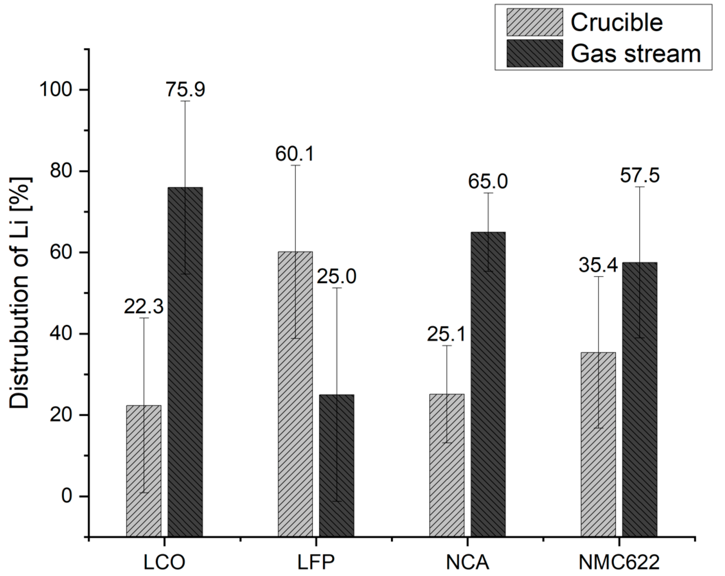
Figure 9 shows the distribution of Li in the reactor and the gas stream. It should be said in advance that an average value of the results was also formed here, and the fluctuation range of this average value is shown with error bars. It can be seen that, apart from the test series with LFP, the majority of the Li could be removed via the gas flow for all other cathode materials. In the result of the LFP test series, the parallel removal of Li and P from the reactor should be emphasized. In Holzer et al. [26], experiments in a similar setup showed the formation of a flame from the exhaust tube, which was attributed to the reaction of elemental phosphorus with atmospheric oxygen. Possibly, the resulting increase in flow velocity allows a correlation to be found that explains the higher amount of Li in the reactor. Although the results of the other cathode materials are fundamentally better, to achieve the highest and most efficient output of Li from the process, the amount in the reactor must be kept to an absolute minimum in the future. Nevertheless, these results also underline the possible reactions in Equations (2) and (3) for conversion to gaseous lithium leaving the reactor chamber.

3.3 Discussion and Comparison with Previous Experiments

As mentioned above, detailed investigations of the process have already been carried out in another reactor design, discussed in detail in Holzer et al. [26] and Windisch-Kern et al. [28,
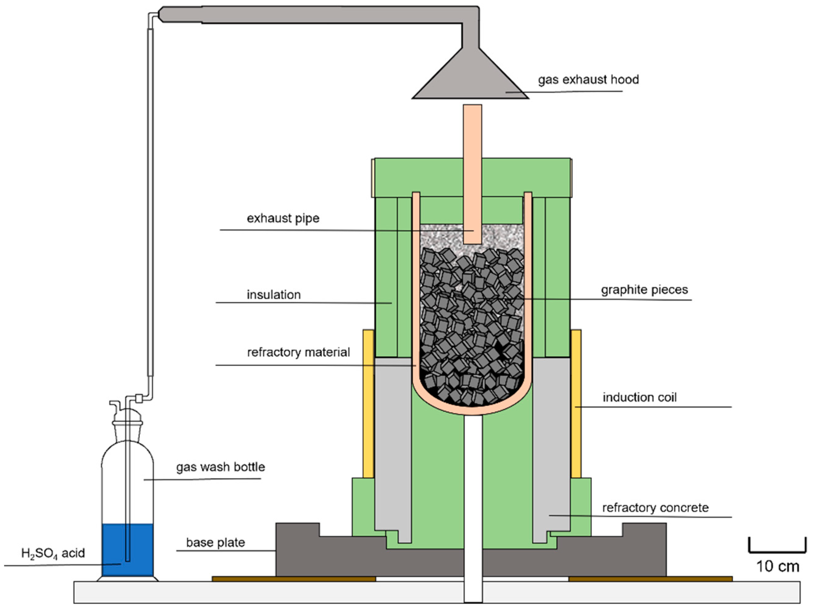
41]. The reactor design was an Al2O3 ceramic ring attached to a refractory concrete floor with a refractory mortar. The system with the graphite filling and the basic plant design was identical to the one used in the test described in this paper. Figure 10 shows the results of lithium removal from the solid fractions in the different reactor designs using distinct cathode materials. It should be mentioned that neither the crucible material in contact with the cathode material nor, to some extent, the refractory mortar were analyzed during the tests in the setup with the Al2O3 design. Thus, no statement can be made as to what percentage of the Li removed from the solid fraction could be removed from the reactor or was deposited in the reactor components. Therefore, the experimental data and results from Windisch-Kern et al. [26,30] and Holzer et al. [23] were supplemented by those extensive considerations, as described in the Section 3.1 InduMelt experiments and inserted into the following plot.
Nevertheless, the trend of high lithium removal from the solid products shown in Figure 6 is confirmed by the results in the other publications. While the results for LCO and NMC622 are consistently above 90%, and similar values for both the Al2O3 build-up and the MgO design, there are several percentage points in between for LFP and NCA. However, for the latter cathode materials, the difference shows a positive trend toward even higher removal rates, which is an interesting finding, especially for the further development of the reactor design toward the continuous process. In this first development step, which essentially consists of a fitting with fewer components in contact with the cathode material, an improvement in lithium removal could already be achieved.
In the following, the targets for Li recovery of 35% by 2025 and 70% by 2030 published in the 2020 proposal for the amendment of battery regulation EU Directive 2006/66/EC [12] are included in the consideration. These goals are not only achieved in all tests, but, in some cases, could have been far exceeded. However, further influencing factors must be included in interpreting these results to ensure the final comparability of the results achieved in the tests with the EU specifications.
Let the most important point be taken as a starting point: We are not talking about an industrial process with the InduMelt system presented here, but about a pre-pilot system in batch operation. This fact must always be taken into account when considering the results demonstrated. Compared to a continuous process, the refractory material’s limited thermomechanical properties only allow low heating rates of the cathode material. On an industrial scale, running in a batch process is not feasible, and continuous feeding is indispensable. Continuous operation automatically implies that the waste stream is fed onto the hot bed, which is why the reactions, depending on the process control, may possibly already lead to partial outgassing of elements at this point due to accelerated kinetics. Therefore, the positioning of the gas vent and optimized temperature control can have a significantly favorable effect on more efficient Li removal from the reactor. The same is applicable for an adequate position of the P removal. As shown in Section 3.2, the Li reaction route is highly likely to be argued from LiMeO2 to Li2CO3 and, due to the excess C, to Li2C2. Latter consequently dissociates to gaseous Li and solid C. Taking into account the boiling point of elemental Li of 1342 °C [42], it can be assumed with the knowledge provided in the Materials and Methods section that the estimated 1550 °C process temperature for the liquefaction of the metals Co and Ni is not necessary for the recovery of Li. This subsequently influences the process design of the continuous reactor setup. In this respect, a multi-zone system with different temperature profiles can be considered for energy-efficient operation.
However, the results of this series of experiments, whereby diffusion of Li into the crucible material has occurred, have additionally shown that the selection of the crucible material contributes significantly to Lithium’s output rate. Even though the results in the MgO crucible largely showed higher potential than in the Al2O3 crucible, the high degree of diffusion of different elements from the battery material into the crucible wall means that this reactor material should not be used for a continuous process. An adequate choice of crucible constituents should be made in the subsequent research activities, for example, through intensive trials with different crucible materials. In this respect, other points of research activity are the behavior of crucible materials under continuous loading and the influence of coatings on the crucible surface. This research must subsequently also consider the caking on the crucible, which was consistently observed in these test series and may gradually reduce the reactor diameter in continuous operation. Another possible approach to avoid packing, but also to reduce the contact area between waste gases and the refractory and thus prevent the above-mentioned diffusion of Li into the reactor, is the ratio of the reactor diameter to the material feed area.
Referring to the results in the presence of P in LFP, for the continuous process, care should be taken to minimize the contact time or area between iron and phosphorus to prevent iron phosphide formation, as previously described by Ponak [32]. The migration of the gas through the packed bed and the sample material must be prevented. In this case, gas removal close to the point of origin would be appropriate.
Beyond these plant engineering improvements, the post-treatment of the removed gas stream is of crucial importance from an overall process perspective. The future design of this process step is essential for the efficient recovery of Li and, subsequently, the balance concerning the actual recovery rate of Li from the overall process. However, this requires in-depth experimental research steps to describe the kinetics of the reaction mechanisms of complex lithium metal oxides that actually take place. From the point of view of a future industrial application, additional attention must be paid to safety aspects, such as possible toxicity or corrosive properties. Especially due to the large number of additional elements in a waste stream from spent LIB compared to the pure cathode material used here, this issue is of immense importance for all further development steps. In this context, especially noted must be aluminum from the conductor foils. Due to the ignoble properties of Al, oxidation of Al happens once a contact between the metal and oxygen occurs. Since the active material mainly consists of metal oxides, it is very likely that Al is either oxidized or not being reduced and, therefore, slagged. This mechanism’s highly exothermic property, called aluminothermic reaction, is a safety issue and thermodynamic limitation. Thus, the process is capped to a specific amount of Al [43]. This critical category of future research topics also includes the post-treatment route of the resulting solid fraction, preferably the metal alloy, and the slag phase’s separated treatment. The removal of oxygen, lithium, and carbon during the reduction process results in a mass loss of up to 50%. Thus, the described pyrometallurgical process significantly lowers the number of intermediate products (i.e., the metal alloy) and, consequently, also the effort in downstream hydrometallurgical refining processes. This, in turn, conserves resources and increases the efficiency of the entire recycling process.
As can be seen from these explanations, many research questions need to be solved before the system is ready for industrial use, which are only the most obvious ones at this point, and others will be added in the course of the ongoing R&D work. Due to TRL3, the results presented here cannot be used as comparative data with industrial plants. Particularly noteworthy is the current relatively high fluctuation range of the results in the repeat tests. On the one hand, there are a lot of adjustment screws up to TRL9, but above all, the continuous feeding and dimensional scaling will provide more stable results over a more extensive flow rate range. Nevertheless, as mentioned previously, it was qualitatively established at this point over several trials and different cathode materials that Li and P can be extracted via the gas phase, and low lithium and low phosphorus alloy can be obtained.
In general, a special requirement for the overall process’s design process chain, but also as an issue in the further development of the InduMelt plant, is the waste stream, which fluctuates in its composition. In detail, this involves how the recycling process, i.e., from collection to metallurgy, must be designed and interconnected to deal with the different battery types. As in many metallurgical processes, the more homogeneous the input stream, the easier an optimum product quality can be achieved. In this respect, the sorting of the different types already sets the course for how the downstream steps must look and what compositions they must be able to handle. For this reason, a key success factor in designing an efficient recycling system is that the individual process steps are coordinated at each stage of further engineering. In the future, this will be one of the primary considerations in developing the InduMelt plant.
Finally, it should be noted that for future comparison of the achieved recovery with the EU requirements, such issues as the technical implementation of a post-treatment route have to be clarified. The resulting products are only comparable after implementing the pyrometallurgical process used here into an overall strategy.

Author Contributions

Conceptualization, A.H.; methodology, A.H.; investigation, A.H. and S.W.-K.; resources, A.H., S.W.-K. and L.W.; writing—original draft preparation, A.H.; writing—review and editing, A.H., L.W., S.W.-K. and H.R.; visualization, A.H.; supervision, H.R.; project administration, A.H.; funding acquisition, H.R. All authors have read and agreed to the published version of the manuscript.

Funding

This paper is supported by the Zukunftsfonds Steiermark with funds from the province of Styria, Austria, grant number GZ: ABT08-189002/2020 PN:1305.

Data Availability Statement

The data presented in this study are available upon request from the corresponding author.

Conflicts of Interest

The authors declare no conflict of interest. The funders had no role in the design of the study; in the collection, analyses, or interpretation of data; in the writing of the manuscript, or in the decision to publish the results.

References

  1. Doukas, H.; Nikas, A.; González-Eguino, M.; Arto, I.; Anger-Kraavi, A. From Integrated to Integrative: Delivering on the Paris Agreement. Sustainability 2018, 7, 2299. [Google Scholar] [CrossRef]
  2. Dimitrov, R.; Hovi, J.; Sprinz, D.F.; Sælen, H.; Underdal, A. Institutional and environmental effectiveness: Will the Paris Agreement work? WIREs Clim. Change 2019, 10, e583. [Google Scholar] [CrossRef]
  3. IEA. Emissions by Sector—Greenhouse Gas Emissions from Energy: Overview—Analysis—IEA. Available online: https://www.iea.org/reports/greenhouse-gas-emissions-from-energy-overview/emissions-by-sector (accessed on 25 April 2022).
  4. PBL Netherlands Environmental Assessment Agency. Trends in Global CO2 and Total Greenhouse Gas Emissions: 2020 Report; PBL Netherlands Environmental Assessment Agency: The Hague, The Netherlands, 2020. [Google Scholar]
  5. Martins, L.S.; Guimarães, L.F.; Botelho Junior, A.B.; Tenório, J.A.S.; Espinosa, D.C.R. Electric car battery: An overview on global demand, recycling and future approaches towards sustainability. J. Environ. Manag. 2021, 295, 113091. [Google Scholar] [CrossRef]
  6. Verma, S.; Dwivedi, G.; Verma, P. Life cycle assessment of electric vehicles in comparison to combustion engine vehicles: A review. Mater. Today 2022, 49, 217–222. [Google Scholar] [CrossRef]
  7. Chordia, M.; Nordelöf, A.; Ellingsen, L.A.-W. Environmental life cycle implications of upscaling lithium-ion battery production. Int. J. Life Cycle Assess. 2021, 26, 2024–2039. [Google Scholar] [CrossRef]
  8. Ellingsen, L.A.-W.; Singh, B.; Strømman, A.H. The size and range effect: Lifecycle greenhouse gas emissions of electric vehicles. Environ. Res. Lett. 2016, 11, 54010. [Google Scholar] [CrossRef]
  9. Nordelöf, A.; Messagie, M.; Tillman, A.-M.; Ljunggren Söderman, M.; van Mierlo, J. Environmental impacts of hybrid, plug-in hybrid, and battery electric vehicles—What can we learn from life cycle assessment? Int. J. Life Cycle Assess. 2014, 19, 1866–1890. [Google Scholar] [CrossRef]
  10. Rajaeifar, M.A.; Raugei, M.; Steubing, B.; Hartwell, A.; Anderson, P.A.; Heidrich, O. Life cycle assessment of lithium-ion battery recycling using pyrometallurgical technologies. J. Ind. Ecol. 2021, 25, 1560–1571. [Google Scholar] [CrossRef]
  11. European Commission. Strategic Dependencies and Capacities: SWD (2021) 352 Final. 2021. Available online: https://ec.europa.eu/info/sites/default/files/swd-strategic-dependencies-capacities_en.pdf (accessed on 25 April 2022).
  12. European Parliament. DIRECTIVE 2006/66/EC OF THE EUROPEAN PARLIAMENT AND OF THE COUNCIL of 6 September 2006 on Batteries and Accumulators and Waste Batteries and Accumulators and Re-Pealing Directive 91/157/EEC: L 266/1. 2006. Available online: https://eur-lex.europa.eu/legal-content/EN/TXT/PDF/?uri=CELEX:32006L0066&from=DE (accessed on 25 April 2022).
  13. European Commission. Critical Raw Materials for Strategic Technologies and Sectors in the EU: A Foresight Study; European Commission: Brussels, Belgium; Luxembourg, 2020. [Google Scholar] [CrossRef]
  14. Sojka, R.; Pan, Q.; Billman, L. Comparative study of lithium-ion battery recycling processes. In Proceedings of the 25th International Congress for Battery Recycling ICBR 2020, Salzburg, Austria, 16–18 September 2020. [Google Scholar]
  15. Windisch-Kern, S.; Gerold, E.; Nigl, T.; Jandric, A.; Altendorfer, M.; Rutrecht, B.; Scherhaufer, S.; Raupenstrauch, H.; Pomberger, R.; Antrekowitsch, H. Recycling chains for lithium-ion batteries: A critical examination of current challenges, opportunities and process dependencies. Waste Manag. 2022, 138, 125–139. [Google Scholar] [CrossRef]
  16. Nasser, O.A.; Petranikova, M. Review of Achieved Purities after Li-ion Batteries Hydrometallurgical Treatment and Impurities Effects on the Cathode Performance. Batteries 2021, 7, 60. [Google Scholar] [CrossRef]
  17. Wesselborg, T.; Virolainen, S.; Sainio, T. Recovery of lithium from leach solutions of battery waste using direct solvent extraction with TBP and FeCl3. Hydrometallurgy 2021, 202, 105593. [Google Scholar] [CrossRef]
  18. Sattar, R.; Ilyas, S.; Kousar, S.; Khalid, A.; Sajid, M.; Bukhari, S.I. Recycling of end-of-life LiNixCoyMnzO2 batteries for rare metals recovery. Environ. Eng. Res. 2020, 25, 88–95. [Google Scholar] [CrossRef]
  19. Lv, W.; Wang, Z.; Cao, H.; Sun, Y.; Zhang, Y.; Sun, Z. A Critical Review and Analysis on the Recycling of Spent Lithium-Ion Batteries. ACS Sustain. Chem. Eng. 2018, 6, 1504–1521. [Google Scholar] [CrossRef]
  20. Munir, H.; Srivastava, R.R.; Kim, H.; Ilyas, S.; Khosa, M.K.; Yameen, B. Leaching of exhausted LNCM cathode batteries in ascorbic acid lixiviant: A green recycling approach, reaction kinetics and process mechanism. J. Chem. Technol. Biotechnol. 2020, 95, 2286–2294. [Google Scholar] [CrossRef]
  21. Santos, M.D.; Garde, I.A.A.; Ronchini, C.M.B.; Filho, L.C.; de Souza, G.B.M.; Abbade, M.L.F.; Regone, N.N.; Jegatheesan, V.; de Oliviera, J.A. A technology for recycling lithium-ion batteries promoting the circular economy: The RecycLib, Resources. Conserv. Recycl. 2021, 175, 105863. [Google Scholar] [CrossRef]
  22. Kaksonen, A.H.; Boxall, N.J.; Gumulya, Y.; Khaleque, H.N.; Morris, C.; Bohu, T.; Cheng, K.Y.; Usher, K.M.; Lakaniemi, A.-M. Recent progress in biohydrometallurgy and microbial characterization. Hydrometallurgy 2018, 180, 7–25. [Google Scholar] [CrossRef]
  23. Baniasadi, M.; Vakilchap, F.; Bahaloo-Horeh, N.; Mousavi, S.M.; Farnaud, S. Advances in bioleaching as a sustainable method for metal recovery from e-waste: A review. J. Ind. Eng. Chem. 2019, 76, 75–90. [Google Scholar] [CrossRef]
  24. Zheng, X.; Zhu, Z.; Lin, X.; Zhang, Y.; He, Y.; Cao, H.; Sun, Z. A Mini-Review on Metal Recycling from Spent Lithium Ion Batteries. Engineering 2018, 4, 361–370. [Google Scholar] [CrossRef]
  25. Nakajima, K.; Takeda, O.; Miki, T.; Matsubae, K.; Nagasaka, T. Thermodynamic analysis for the controllability of elements in the recycling process of metals. Environ. Sci. Technol. 2011, 11, 4929–4936. [Google Scholar] [CrossRef]
  26. Holzer, A.; Windisch-Kern, S.; Ponak, C.; Raupenstrauch, H. A novel pyrometallurgical recycling process for Lithium-Ion-Batteries and its use in recycling LCO and LFP. Metals 2021, 2021, 149. [Google Scholar] [CrossRef]
  27. European Comission. COM(2020)474—Critical Raw Materials Resilience: Charting a Path towards Greater Security and Sustainability. Available online: https://ec.europa.eu/transparency/documents-register/detail?ref=COM (accessed on 16 August 2022).
  28. Windisch-Kern, S.; Holzer, A.; Wiszniewski, L.; Raupenstrauch, H. Investigation of Potential Recovery Rates of Nickel, Manganese, Cobalt, and Particularly Lithium from NMC-Type Cathode Materials (LiNixMnyCozO2) by Carbo-Thermal Reduction in an Inductively Heated Carbon Bed Reactor. Metals 2021, 11, 1844. [Google Scholar] [CrossRef]
  29. Mao, J.; Ye, C.; Zhang, S.; Xie, F.; Zeng, R.; Davey, K.; Guo, Z.; Qiao, S. Toward practical lithium-ion battery recycling: Adding value, tackling circularity and recycling-oriented design. Energy Environ. Sci. 2022, 15, 2732–2752. [Google Scholar] [CrossRef]
  30. Sommerville, R.; Zhu, P.; Rajaeifar, M.A.; Heidrich, O.; Goodship, V.; Kendrick, E. A qualitative assessment of lithium ion battery recycling processes. Resour. Conserv. Recycl. 2021, 165, 105219. [Google Scholar] [CrossRef]
  31. Mossali, E.; Picone, N.; Gentilini, L.; Rodrìguez, O.; Pérez, J.M.; Colledani, M. Lithium-ion batteries towards circular economy: A literature review of opportunities and issues of recycling treatments. J. Environ. Manag. 2020, 264, 110500. [Google Scholar] [CrossRef] [PubMed]
  32. Ponak, C. Carbo-Thermal Reduction of Basic Oxygen Furnace Slags with Simultaneous Removal of Phosphorus via the Gas Phase. Master’s Thesis, Montanuniversitaet Leoben, Leoben, Austria, 2019. [Google Scholar]
  33. Ponak, C.; Mally, V.; Windisch, S.; Holzer, A.; Raupenstrauch, H. Phosphorus Gasification during the Re-duction of basic Oxygen Furnace Slags in a Novel Reactor Concept. Adv. Mater. Lett. 2020, 11, 1–7. [Google Scholar] [CrossRef]
  34. Seck, G.S.; Hache, E.; Barnet, C. Potential bottleneck in the energy transition: The case of cobalt in an accelerating electro-mobility world. Resour. Policy 2022, 75, 102516. [Google Scholar] [CrossRef]
  35. Liu, K.; Liu, Y.; Lin, D.; Pei, A.; Cui, Y. Materials for lithium-ion battery safety. Sci. Adv. 2018, 4, eaas9820. [Google Scholar] [CrossRef]
  36. Chen, Y.; Kang, Y.; Zhao, Y.; Wang, L.; Liu, J.; Li, Y.; Liang, Z.; He, X.; Li, X.; Tavajohi, N.; et al. A review of lithium-ion battery safety concerns: The issues, strategies, and testing standards. J. Energy Chem. 2021, 59, 83–99. [Google Scholar] [CrossRef]
  37. Kwon, O.; Sohn, I. Fundamental thermokinetic study of a sustainable lithium-ion battery pyrometallurgical recycling process, Resources. Conserv. Recycl. 2020, 158, 104809. [Google Scholar] [CrossRef]
  38. Abegg, R.; Auerbach, F. Handbuch der Anorganischen Chemie: Zweiter Band, Erste Abteilung; S. Hirzel Verlag: Leipzig, Germany, 1908; Available online: https://archive.org/details/handbuchderanor00koppgoog/page/135/mode/1up?view=theater (accessed on 27 April 2022).
  39. Makuza, B.; Tian, Q.; Guo, X.; Chattopadhyay, K.; Yu, D. Pyrometallurgical options for recycling spent lithium-ion batteries: A comprehensive review. J. Power Source 2021, 491, 229622. [Google Scholar] [CrossRef]
  40. Schlesinger, M.E. The thermodynamic properties of phosphorus and solid binary phosphides. Chem. Rev. 2002, 102, 4267–4301. [Google Scholar] [CrossRef] [PubMed]
  41. Windisch-Kern, S.; Holzer, A.; Ponak, C.; Raupenstrauch, H. Pyrometallurgical Lithium-Ion-Battery Recycling: Approach to Limiting Lithium Slagging with the InduRed Reactor Concept. Processes 2021, 9, 84. [Google Scholar] [CrossRef]
  42. Outotec Research Center; Roine, A. HSC Chemistry 7; Outotec: Espoo, Finland, 2009. [Google Scholar]
  43. Holzer, A.; Baldauf, M.; Wiszniewski, L.; Windisch-Kern, S.; Raupenstrauch, H. Influence of Impurities on the High-Temperature Behavior of the Lithium-Ion Battery Cathode Material NMC Under Reducing Conditions for Use in the InduRed Reactor Concept. Detritus 2022, in press. [Google Scholar] [CrossRef]
Figure 1. Schematic illustration of the so-called InduMelt crucible concept [23].
Metals 12 01642 g001
Figure 2. Examples of the products from the InduMelt experiments with LCO: (a) Slag; (b) Metal; (c) Powder.
Metals 12 01642 g002
Figure 3. Examples of the products from the InduMelt experiments with LFP: (a) Slag; (b) Metal; (c) Powder sparse magnetic; (d) Powder.
Metals 12 01642 g003
Figure 4. Examples of the products from the InduMelt experiments with NCA: (a) Slag; (b) Metal; (c) Powder sparse magnetic; (d) Powder.
Metals 12 01642 g004
Figure 5. Examples of the products from the InduMelt experiments with NMC622: (a) Slag; (b) Metal; (c) Powder sparse magnetic; (d) Powder.
Metals 12 01642 g005
Figure 6. Transfer coefficients of the individual elements including variance because of disturbed exhaust gas discharge: InduMelt experiments with (a) LCO, (b) LFP, (c) NCA, and (d) NMC.
Metals 12 01642 g006
Figure 7. Example of the crucible appearance after trial LFP V2 during sampling for analyses: (a) Crucible over the height; (b) Top part; (c) Middle area; (d) Bottom.
Metals 12 01642 g007
Figure 8. Mass distribution of adhesion to and absorption into the reactor wall of the respective elements: (a) Alteration in the trial with LCO and LFP, (b) NCA, and (c) NMC622.
Metals 12 01642 g008aMetals 12 01642 g008b
Figure 9. Mass distribution of adhesion to and absorption into the reactor wall of the respective elements.
Metals 12 01642 g009
Figure 10. Comparison of Li removal from solid fractions in InduMelt experiments in the Al2O3 crucible design [26,28,41] and that with MgO.
Metals 12 01642 g010
Table 1. Concentration of relevant elements in the samples used for the InduMelt experiments in wt.%.
CompoundLiCoNiMnAlFePC
LCO_C 15.6748.17-----20.00
LFP_C 13.52----28.3215.7124.00
NCA_C 15.884.9939.76-2.28--20.00
NMC622_C 15.739.7329.079.07---20.00
1 Difference to 100% detection rate due to the proportion of O.
Table 2. Sample mass at the beginning of the InduMelt experiment with LCO and weight of the resulting products in grams.
TrialInput [g]Slag [g]Powder Sparse Magnetic [g]Metal [g]Powder [g]
LCO V1549.61.3-242.3 35.2
LCO V2551.02.4-217.177.5
Table 3. Content of Li and Co in the individual product phases of LCO V1 and LCO V2 in wt.%.
ElementSlag [%]Powder Sparse Magnetic [%]Metal [%]Powder [%]
LCOV1|V2V1|V2V1|V2V1|V2
Li5.59 1|15.80 2- 1|- 20.12 1|0.03 20.69 1|0.03 2
Co3.30 1|0.14 2- 1|- 293.90 1|83.50 266.60 1|81.30 2
Sum 38.89 1|15.94 2- 1|- 294.02 1|83.53 267.29 1|81.33 2
1 Trial 1 (LCO V1). 2 Trial 2 (LCO V2). 3 Difference to 100% detection rate due to the proportion of C and O in the fractions or measurement uncertainties and complex sampling.
Table 4. Results of the washing water analysis from the gas scrubber in the tests with LCO in mg/l.
TrialLi [mg/L]
LCO V1 11230.00
LCO V2 2860.00
1 Sample quantity for analysis: 150 mL. 2 Sample quantity for analysis: 100 mL.
Table 5. Sample mass at the beginning of the InduMelt experiment with LFP and weight of the resulting products in grams.
TrialInput [g]Slag [g]Powder Sparse Magnetic [g]Metal [g]Powder [g]
LFP V1548.91.88.7145.836.9
LFP V2550.10.98.9168.760.9
Table 6. Content of Li, Fe, and P in the individual product phases of LFP V1 and LFP V2 in wt.%.
ElementSlag [%]Powder Sparse Magnetic [%]Metal [%]Powder [%]
LFPV1|V2V1|V2V1|V2V1|V2
Li0.37 1|6.73 21.91 1|3.62 20.22 1|0.81 23.87 1|3.43 2
Fe0.07 1|4.01 20.60 1|0.70 277.10 1|69.90 246.60 1|43.00 2
P0.07 1|7.96 20.78 1|1.98 214.30 1|18.80 212.80 1|14.40 2
Sum 30.51 1|18.70 23.29 1|6.30 291.62 1|89.21 263.27 1|60.83 2
1 Trial 1 (LFP V1). 2 Trial 2 (LFP V2). 3 Difference to 100% detection rate due to the proportion of C and O in the fractions or measurement uncertainties and complex sampling.
Table 7. Results of the washing water analysis from the gas scrubber in the tests with LFP in mg/L.
TrialLi [mg/L]P [mg/L]
LFP V1 17.6087.00
LFP V2 2310.003130.00
1 Sample quantity for analysis: 100 mL. 2 Sample quantity for analysis: 250 mL.
Table 8. Sample mass at the beginning of the InduMelt experiment with NCA and weight of the resulting products in grams.
TrialInput [g]Slag [g]Powder Sparse Magnetic [g]Metal [g]Powder [g]
NCA V1550.5-2.5225.960.4
NCA V2550.0-4.2230.754.9
NCA V3550.01.03.1223.658.4
Table 9. Content of Li, Co, Ni, and Al in the individual product phases of NCA V1, NCA V2, and NCA V3 in wt.%.
TrialSlag [%]Powder Sparse Magnetic [%]Metal [%]Powder [%]
NCAV1|V2|V3V1|V2|V3V1|V2|V3V1|V2|V3
Li- 1|- 2|12.80 313.70 1|9.76 2|9.20 30.20 1|0.29 2|0.06 34.39 1|5.26 2|3.28 3
Co- 1|- 2|0.10 30.19 1|0.09 2|0.10 39.54 1|9.13 2|9.81 35.07 1|4.78 2|6.20 3
Ni- 1|- 2|1.17 34.78 1|2.42 2|1.55 386.90 1|89.60 2|94.30 347.30 1|43.30 2|61.40 3
Al- 1|- 2|2.49 32.06 1|1.72 2|1.85 30.63 1|0.48 2|0.79 32.14 1|1.96 2|3.48 3
Sum 4- 1|- 2|16.56 320.73 1|13.99 2|12.70 397.26 1|99.49 2|104.96 358.90 1|55.30 2|74.36 3
1 Trial 1 (NCA V1). 2 Trial 2 (NCA V2). 3 Trial 3 (NCA V3). 4 Difference to 100% detection rate due to the proportion of C and O in the fractions or measurement uncertainties and complex sampling.
Table 10. Results of the washing water analysis from the gas scrubber in the tests with NCA in mg/L.
TrialLi [mg/L]
NCA V1 165.00
NCA V2 265.00
NCA V3 3960.00
1 Sample quantity for analysis: 200 mL. 2 Sample quantity for analysis: 200 mL. 3 Sample quantity for analysis: 100 mL.
Table 11. Sample mass at the beginning of the InduMelt experiment with NMC622 and weight of the resulting products in grams.
TrialInput [g]Slag [g]Powder Sparse Magnetic [g]Metal [g]Powder [g]
NMC622 V1550.2-3.4225.754.3
NMC622 V2550.2-4.2220.160.5
NMC622 V3549.43.010.9231.649.2
Table 12. Content of Li, Co, Ni, and Mn in the individual product phases of NMC622 V1, NMC622 V2, and NMC622 V3 in wt.%.
TrialSlag [%]Powder Sparse Magnetic [%]Metal [%]Powder [%]
NMC622V1|V2|V3V1|V2|V3V1|V2|V3V1|V2|V3
Li- 1|- 2|11.00 38.26 1|6.95 2|5.50 30.17 1|0.29 2|0.10 32.95 1|2.88 2|2.16 3
Co- 1|- 2|0.01 30.26 1|0.12 2|0.61 318.30 1|18.70 2|20.80 313.20 1|11.90 2|14.80 3
Ni- 1|- 2|0.06 31.52 1|0.45 2|1.94 357.90 1|58.80 2|66.30 334.50 1|32.20 2|46.00 3
Mn- 1|- 2|0.12 30.31 1|0.18 2|0.76 316.70 1|16.20 2|18.90 312.40 1|11.00 2|14.00 3
Sum 4- 1|- 2|11.20 310.35 1|7.69 2|8.81 393.07 1|93.99 2|106.10 363.05 1|57.98 2|76.96 3
1 Trial 1 (NMC622 V1). 2 Trial 2 (NMC622 V2). 3 Trial 3 (NMC622 V3). 4 Difference to 100% detection rate due to the proportion of C and O in the fractions or measurement uncertainties and complex sampling.
Table 13. Results of the washing water analysis from the gas scrubber in the tests with NMC622 in mg/L.
TrialLi [mg/L]
NMC622 V1 132.00
NMC622 V2 220.00
NMC622 V3 3980.0
1 Sample quantity for analysis: 200 mL. 2 Sample quantity for analysis: 200 mL. 3 Sample quantity for analysis: 100 mL.
Table 14. Mass distribution of Fe and P in the reactor for the InduMelt experiments with LFP.
TrialLFP V1 [g]LFP V2 [g]Difference [%]
Fe17.82.6−85.4
P26.06.3−75.7
Table 15. Weight difference of the reactor before and after the individual InduMelt trials.
TrialWeight Reactor before Trial [g]Weight Reactor after Trial [g]Difference [g]
LCO V14655.04766.2111.2
LCO V2 14761.54828.967.4
LFP V14650.24813.6163.4
LFP V2 1,24829.24911.081.8
NCA V1 15083.95161.777.8
NCA V2 1,25161.75219.557.8
NCA V35011.25091.179.9
NMC V1 14786.84885.198.3
NMC V2 1,24885.14947.061.9
NMC V35071.85154.182.3
1 Dual use. 2 Second experiment with the reactor.
Table 16. Mass distribution of the elements in the reactor for the InduMelt experiments with NCA.
TrialNCA V3 [g]NCA V1/V2 [g]Difference [%]
Li11.732.764.2
Co0.60.0−100
Ni7.12.5−65.2
Al---
Table 17. Mass distribution of the elements in the reactor for the InduMelt experiments with NMC622.
TrialNMC622 V3 [g]NMC622 V1/V2 [g]Difference [%]
Li17.044.161.4
Co0.20.982.3
Ni1.32.954.4
Mn2.27.671.7
Publisher’s Note: MDPI stays neutral with regard to jurisdictional claims in published maps and institutional affiliations.

