
Magnetocaloric Effect in CoFe-Electroplated Ni50Mn33In16Cr1 Alloy

1
Department of Physics, Faculty of Science, Kasetsart University, Bangkok 10900, Thailand
2
Thailand Center of Excellence in Physics, Commission on Higher Education, Bangkok 10400, Thailand
3
School of Science and Technology, Sukhothai Thammathirat Open University, Nonthaburi 11120, Thailand
*
Author to whom correspondence should be addressed.
Metals 2022, 12(12), 2137; https://doi.org/10.3390/met12122137
Submission received: 10 August 2022
/
Revised: 11 November 2022
/
Accepted: 7 December 2022
/
Published: 13 December 2022
(This article belongs to the Section Metal Failure Analysis)
Abstract
:A high-saturation magnetization CoFe layer was electroplated onto Ni50Mn33In16Cr1 alloy using a magnetic field assistance electroplating bath. This CoFe-coated alloy can function as an active magnetic regenerator owing to its magnetocaloric effect. The CoFe coating layer did not affect the entropy change calculated from the isothermal magnetization of the alloy, but it significantly affected the temperature variation of the alloy by changing the externally applied magnetic field. The temperature change of the CoFe-coated alloy increases with increasing CoFe coating times. By comparing with the as-sintered alloy, a maximum increase of 150% in temperature change can be observed in the alloy coated with CoFe for 2 h.
1. Introduction
The magnetocaloric effect (MCE) is the phenomenon of the temperature or entropy change of magnetic materials due to the variation of the magnetic field [1]. The total magnetic entropy of magnetic materials at a constant pressure can be expressed as:
where ST is the total entropy, SM is the magnetic entropy, Sr is the lattice entropy caused by the vibrations of the crystal lattice, and Se is the electronic entropy attributed to the material’s free electrons [2]. In an isothermal magnetization process, the lattice entropy and the electronic entropy are independent of an applied magnetic field. When such a material is magnetized, its magnetic moments are aligned in the direction of the applied magnetic field, leading to reductions in both the magnetic entropy and the total entropy. If the material is magnetized under adiabatic conditions, the total entropy is constant. Therefore, when the reduction in magnetic entropy is compensated by an increase in the lattice entropy, the temperature of the material increases as a result. The magnetocaloric materials with large magnetic entropy and temperature changes during the magnetized/demagnetized process are required for magnetic refrigeration application.
The MCE materials used as the magnetic regenerator of the prototype magnetic refrigerator are Gd5Si4-xGex [3,4,5], La(Fe1-xSix)13 [6,7,8], MnFeP(As, Ge, Si) [9,10,11] and NiMnX (X = Sn, Sb, In and Ga) [12,13,14]. Our previous study showed that liquid phase sintered Ni50Mn34-xIn16Crx alloys exhibit a near room-temperature magnetocaloric effect [15]. The entropy changes and temperature at maximum entropy can be tuned by the Cr contents in the alloy. However, the dopant may be partially soluble in the major component, but eventually, the solubility limit was reached at a certain concentration. With a further increase in concentration, the dopant ions may segregate at grain boundaries [16,17]. The MCE materials prepared by a rapid heating and cooling process require heat treatment to decrease defects and stress relaxation and entropy change [18,19,20]. Therefore, other techniques used to improve the entropy and temperature changes of MCE materials must be investigated. Some studies aim to find a new way to improve the MCE properties by coating with ferromagnetic materials [21,22]. Coating ferromagnetic material on the nanoparticles shows enhanced coercivity, magnetization, and alteration in the maximum entropy. This large enhancement is attributed to the enhanced inter-particle interaction, which is affected by the metallic shell over the relatively weaker dipolar interaction in the sample with the modification of the surface spin structure. In view of the background, it is interesting to translate this coating process to a macro-scale fabrication and study the feasibility of coating MCE with ferromagnetic materials.
The introduction of the magnetic field in the electrodeposition process (referred to as magneto-electrodeposition) can be widely used for the coating of metals and alloys on suitable substrates [23,24,25]. The influence of the magnetic field on the electrodeposition is mainly attributed to the magnetic force on the ions or charge transfer, which significantly influence the structure and properties during coating [23,24,25]. Kołodziejczyk reported the influence of the magnetic field on the properties of the electroplated film [26]. It indicated that the application of a magnetic field (200 mT) has a significant impact on the magnetic anisotropy of the electroplated film.
In this study, we investigate the effect of the high saturation magnetization CoFe coating layer on the magnetocaloric properties of Ni50Mn33In16Cr1 alloy. The high magnetization of the CoFe coating layer increases the effective magnetization of the sample, which is compensated by the lattice entropy in the adiabatic process and results in an increase in the temperature change of the magnetocaloric material.
2. Material and Methods
The Ni50Mn33In16Cr1 alloy was prepared by the liquid phase sintering method followed by our previous study [15]. The as-sintered alloys with a diameter of 8 mm were polished with sandpaper to remove oxide from the surface in order to make the sample surface parallel. They were then attached to the cathode of the electroplating cell.
Figure 1 shows the electroplating cell used in this work. The anodes were platinum wire with a 1 mm diameter. The temperature of the deposition bath was controlled by a refrigerated circulator (PolyScience SD15R-30, PolyScience, Niles, IL, USA). The electroplating cell was placed in the magnetic field generated by a pair of NdFeB permanent magnets of 20 mm diameter. The magnetic field at the center of the electroplating cell (cathode), as measured by a gaussmeter (Lakeshore 455DSP, Lake Shore Cryotronics, Westerville, OH, USA), was 540 mT.
The Cu seed layer was electroplated in 100 mL solution with 9 g of Cu2P2Ox·xH2O, 34.5 g of K4O7P2, and 0.3 mL of NH4OH at the temperature of 333 K with a DC current density of 40 mA/cm2 for 20 min, and the Ni50Mn33In16Cr1 pellet with a diameter of 8.0 mm was used as a cathode. After obtaining Cu of the desired thickness, the electrodes were rinsed with distilled water and then transferred to the CoFe bath for a CoFe deposition. In the CoFe bath, high-purity CoSO4.7H2O, FeSO4.7H2O, NH4Cl, H3BO3, and saccharin powders were mixed in deionized water at concentrations of 0.18, 0.18, 0.50, 0.50, and 0.006 mol/L, respectively. The temperature of the CoFe deposition bath was controlled at 271 K and fed with argon gas to prevent the oxidation of Fe2+. By keeping the DC current density at 30 mA/cm2, the CoFe layer thickness was controlled by the deposition time.
The phase Identification of the alloy and CoFe-coated alloy were carried out with an X-ray diffractometer (XRD; D8 advance, Bruker, Bremen, Germany). The microstructure and elementary composition of the synthesized samples were investigated by using scanning electron microscopy (SEM; Quanta 450, FEI, Hillsboro, OR, USA) equipped with an energy dispersive spectrometer (EDS; X-Max, Oxford instruments, High Wycombe, UK). After removing the CoFe-coated layer on the side edge of the pellet, the magnetization was measured as a function of a magnetic field up to 10 kOe at temperatures of 253–333 K using an in-house-developed vibrating sample magnetometer (VSM; calibrated with a 3 mm-diameter Ni sphere model 730908, Lake Shore Cryotronics, Westerville, OH, USA). The agglomeration size of the particle of the coated film was measured using image analysis (ImageJ program, Version 1.53t, Wayne Rasband and contributors, National Institutes of Health, Bethesda, MD, USA).
The magnetic entropy change (ΔSM) of the samples was calculated from the isothermal M-H curves using the equation:
where M is the magnetization, T is the temperature, and H is the external applied field.
In this work, the temperature change (ΔT) of the sample was directly measured. The sample was attached to a precise platinum thin-film temperature sensor (Innovative Sensor Technology) by using 5.0 × 2.0 × 0.2 mm3 indium foil as the thermally conductive layer. The temperature variation of the sample due to the changing of the magnetic field was detected by the temperature sensor. During the data acquisition process, the temperature of the sample space was automatically controlled at a set point. The temperature change due to the changing of the magnetic field was calculated by using the following relation:
where THA is the maximum detected temperature after applying a magnetic field, and THR is the minimum detected temperature after removing the magnetic field.
3. Results and Discussion
An X-ray diffraction pattern obtained from the sample with a CoFe coating time of 1 h is compared with that of the as-sintered Ni50Mn33In16Cr1, as shown in Figure 2a. The pattern shows the well-defined peaks of the 2 h CoFe-coated alloy matched with the CoFe (00-049-1568) and Cu (01-085-1326) phases. However, the Heusler alloy phase pattern is undetectable because X-ray cannot penetrate through the CoFe and Cu layers. Figure 2b shows the effect of the coating time on the peak pattern of the sample. With increasing coating time, the intensity of the Cu peak (43.317°) decreased due to the increasing CoFe upper layer. Moreover, the Fe peak (01-085-1410) (44.354°) is clearly observed in the sample with a longer coating time since more Fe content is formed in the coating layer [23]. On the other hand, the oxide formed from possible reactions such as Co3O4, FeO, Fe2O3, Fe3O4 CoO, CoFe2O4, and CuO was not observed.
The SEM image and the corresponding elemental mapping in Figure 3 revealed the advantage of using Cu as the seed layer. Without the Cu seed layer, CoFe cannot be uniformly deposited on the as-sintered Ni50Mn33In16Cr1 surface. This result might be explained by the existence of Mn at the surface of the as-sintered sample that can easily form an oxide. This oxide behaves as a passive film which reduces the coating capacity of CoFe. The uniformity of CoFe on the sample can be improved by the electrodeposition of the Cu seed layer on the as-sintered Ni50Mn33In16Cr1. The EDS confirmed the oxygen content, unlike the XRD patterns. This result might be attributed to the oxide formed with an excess of Fe on the surface of the particles in a very small and thin layer. Therefore, the XRD could not detect the peak intensity of the oxide. The darker yellow spot shows the region of a higher concentration of O that is associated with pores and coarse particles. Moreover, the intensity of the O is not as evident as the Co and Fe. Therefore, this coating process could produce the CoFe film without forming a significant oxide phase.
The mass of the CoFe coating layer increased linearly with the deposition time as shown in Figure 4. The results imply that the coating layer thickness increases with the coating time. Based on 2k magnification SEM images of CoFe films (Figure 5a), the distribution of agglomerated particle size and the average agglomeration size were analyzed. The Image J program had been used to measure 25 agglomeration particles. The results indicated that the average agglomerate particle size tends to increase with increasing coating time, as shown in Figure 5b. Furthermore, the surface roughness of the coating layer can be improved by increasing the coating time.
To study the effects of the only layer of CoFe film, this study was conducted by coating CoFe onto the Heusler base layer without the Cu seed layer. The normal sticky tape was placed and pressed onto the CoFe. After that, peeling the tape out of the Heusler surface resulted in obtaining only the film of CoFe with the known direction of the induced magnetic field coating. The in-plane relative magnetization of the CoFe film is compared to that of the out-of-plane direction in Figure 6a. The magnetic moment in the CoFe coating layer prefers to point in the out-of-plane direction corresponding to the field direction generated by the permanent magnet in the electroplating process. This magnetic field induced the alignment of the magnetic moment of the CoFe coating layer in the (110) direction confirmed by the XRD pattern as shown in Figure 2. The saturation magnetization of about 200 emu/g was obtained from the CoFe coating layer and was comparable to the value reported in [27,28]. The in-plane isothermal magnetization curves of the CoFe film at temperatures of 253–333 K are shown in Figure 6b. Under an external magnetic field of 10 kOe, a small change in the maximum magnetization as a function of temperature is observed in the CoFe film, since the ferromagnetic–paramagnetic transition of the CoFe occurs at a higher temperature (about 1230 K) [29].
The isothermal magnetization curves under the maximum external applied field of 10 kOe of the as-sintered Ni50Mn33In16Cr1 alloy and Ni50Mn33In16Cr1/Cu with 2 h-coated CoFe at temperatures of 253–333 K are shown in Figure 7a,b, respectively. The magnetization of the as-sintered alloy decreased with the increasing temperature and became linearly dependent on the applied field close to the magnetic phase transition temperature. The isothermal magnetization curves of the CoFe-coated alloy vary in the same fashion as those of the as-sintered alloy. However, the magnetization of the CoFe-coated alloy is still nonlinear and dependent on the applied field at even higher temperatures due to the existence of the CoFe ferromagnetic layer.
The magnetic entropy changes (|ΔSM|) calculated from the in-plane and out-of-plane isothermal magnetization curves were plotted as a function of temperatures in Figure 8. The entropy changes of the CoFe-coated alloy increased with the increasing temperature and reached a maximum at the magnetic phase transition temperature (Curie temperature; TC) of 300.5 K and then decreased with a further increase in the temperature similar to that of the as-sintered alloy. The superposition of the curves indicated that the CoFe coating layer did not affect the entropy change of the alloy. According to Equation (2), the magnetic entropy change is dependent on the change of the magnetization varied with the measured temperature. Since the magnetization of the CoFe film is rather insensitive to the temperature at 253–333 K, the magnetic entropy change is therefore a result of the variation in the magnetization of the Heusler alloy with the temperature and magnetic field.
The magnetic entropy change calculated for the in-plane isothermal magnetization is higher than that of the out-of-plane. In the out-of-plane measurement, the demagnetization effect can have a significant impact on the obtained data. The actual magnetizing field experienced by the sample (Hint) will be different from the applied field (H):
where M is the sample magnetization and D is the demagnetization factor. For the cylinder sample with length L along the z-axis and diameter d, the longitudinal (Dz) and perpendicular (Dxy) demagnetization factors can be expressed as [30]:
The longitudinal demagnetization factor increases with the increasing d/L ratio and reaches 1 for a very flat cylinder when d L. On the other hand, the flat cylinder has no demagnetization effect within the xy-plane (in-plane).
The variation of temperature of the 0.5–4 h CoFe-coated alloy is compared with that of the as-sintered alloy, as shown in Figure 9. When applying a magnetic field, the temperature of the samples increased rapidly to the maximum value and then gradually decreased until reaching the set-point temperature. After removing the magnetic field, the temperature variation of the sample was similar to that of the applying field process but took place in the opposite direction. The variation of the sample temperature that depends on the magnet when applied or removed can be explained by the magnetic entropy which is compensated for by the lattice entropy. As the magnetization of the CoFe-coated alloy is higher than that of the as-sintered alloy, changing the applied magnetic field can induce a higher magnetic entropy change in the coated alloy. In the adiabatic process, the variation of magnetic entropy is compensated by lattice entropy, and the temperature of the material increases as a result. Therefore, the temperature change of the CoFe-coated alloy is higher than that of the as-sintered alloy without increasing in the variation magnetic entropy of the substrate alloy.
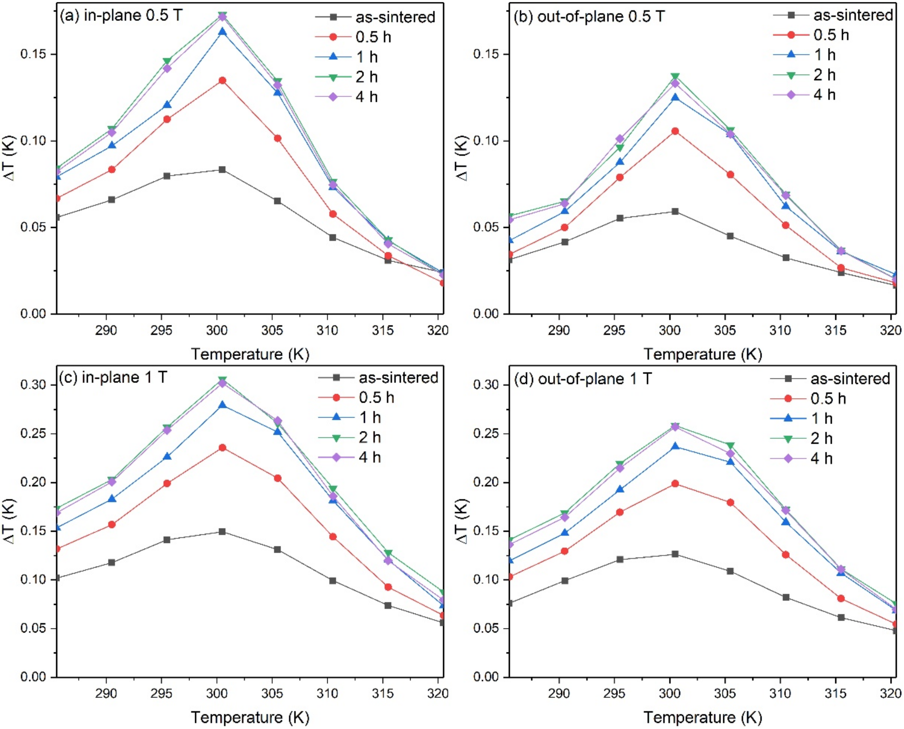
The temperature change (ΔT) due to the changing of the magnetic field 10 kOe of the CoFe-coated alloys is compared to that of the as-sintered sample in Figure 10. The temperature change of the samples increased with increasing temperature and reached its maximum value of 300.5 K, which was equal to that obtained from the indirect measurement method. The maximum temperature change of the CoFe-coated alloy increased with the coating time and reached a maximum for the alloy with a 2 h coating time. When further increased coating time, no increase in the maximum temperature change was observed. These behaviors can be explained by the increase in the magnetic moment of the sample due to the CoFe-coated layer. Since the magnetization of the CoFe layer is higher than that of the Heusler alloy and rather insensitive to the temperature, the magnetic entropy change of the coated alloy is therefore higher than that of the uncoated alloy. Thus, higher temperature changes can be observed in the CoFe-coated alloy. However, the temperature change is nonlinearly dependent on the thickness of the CoFe coating layer due to the variation in the magnetic properties of the CoFe coating layer with increasing coating time or thickness. Since the electronegativity of Co is higher than that of Fe, Co2+ consequently attracts electrons and forms Co more easily in the early stages of electroplating. With the increasing coating time, Fe2+ ions in the electrolyte become higher than the Co2+ ions, and Fe content in the alloy increases as a result. The saturation magnetization of Co1-xFex increases with increasing x and reaches the maximum value before falling upon a further increase in the Fe content [31,32]. Therefore, the temperature change cannot be increased with further increases in coating time.
4. Conclusions
The coating time affects the smoothness and the agglomeration size of the particles. Two hours of coating could improve the smoother surface, showing the growth of an agglomeration size of the particle around 6 μm. The CoFe coating layer did not affect the magnetic entropy change but increased the temperature change of the alloy. The temperature changes increased when increasing the externally applied magnetic field and depending on the demagnetization factor of the sample. The maximum increase of 150% in temperature change at the temperature of about 300 K was observed in the 2 h CoFe-coated alloy. The CoFe coating layer enhanced the temperature change of the MCE materials and may be used to improve the temperature span and efficiency of magnetic refrigerators.
Author Contributions
P.L.—Formal analysis, Investigation, Writing—original draft, Visualization, Methodology; P.J.—Formal analysis, Investigation, Writing—review and editing, Methodology, Funding acquisition, Conceptualization, Supervision; T.C.—Formal analysis, Methodology. All authors have read and agreed to the published version of the manuscript.
Funding
This work was supported by the Thailand Center of Excellence in Physics (Grant No. ThEP-60-PIP-KU2) and The Royal Golden Jubilee Ph. D. Programs under contract No. PHD/0033/2552.
Data Availability Statement
Data presented in this article are available at request from the corresponding author.
Conflicts of Interest
The authors declare that they have no known competing financial interests or personal relationships that could have appeared to influence the work reported in this paper.
References
- Warburg, E. Magnetische Untersuchungen. Ueber einige Wirkungen der Cöercitivkraft. Ann. Der Phys. 1881, 249, 141–164. [Google Scholar] [CrossRef] [Green Version]
- Pecharsky, V.K.; Gschneidner, K.A., Jr.; Pecharsky, A.O.; Tishin, A.M. Thermodynamics of the magnetocaloric effect. Phys. Rev. B 2001, 64, 144406. [Google Scholar] [CrossRef]
- Herrero, A.; Oleaga, A.; Manfrinetti, P.; Provino, A.; Salazar, A. Critical behavior of the ferromagnetic transition in GdSc(Si,Ge) intermetallic compounds. Intermetallics 2018, 101, 64–71. [Google Scholar] [CrossRef]
- Matsumoto, K.T.; Hiraoka, K. Magnetocaloric effect in Gd-based ferromagnet GdZn2. J. Magn. Magn. Mater. 2017, 423, 318–320. [Google Scholar] [CrossRef]
- Xue, L.; Li, J.; Yang, W.; Yuan, C.; Shen, B. Effect of Fe substitution on magnetocaloric effects and glass-forming ability in Gd-based metallic glasses. Intermetallics 2018, 93, 67–71. [Google Scholar] [CrossRef]
- Vuong, V.-H.; Do-Thi, K.-A.; Nguyen, D.-T.; Nguyen, Q.-H.; Hoang, N.-N. Low field magnetocaloric effect in bulk and ribbon alloy La(Fe 0.88 Si 0.12 ) 13. Phys. B Condens. Matter 2018, 532, 115–118. [Google Scholar] [CrossRef]
- Funk, A.; Freudenberger, J.; Waske, A.; Krautz, M. Getting magnetocaloric materials into good shape: Cold-working of La(Fe, Co, Si)13 by powder-in-tube-processing. Mater. Today Energy 2018, 9, 223–228. [Google Scholar] [CrossRef]
- Liu, J.; He, C.; Zhang, M.; Yan, A. A systematic study of the microstructure, phase formation and magnetocaloric properties in off-stoichiometric La-Fe-Si alloys. Acta Mater. 2016, 118, 44–53. [Google Scholar] [CrossRef]
- Lee, A.; Kim, S.; Kim, Y.; Lee, M. The effect of refractory (Zr, Hf) elements on the magnetocaloric property of Mn-based alloys. Appl. Surf. Sci. 2019, 478, 1004–1008. [Google Scholar] [CrossRef]
- Govor, G.; Mitsiuk, V.; Nikitin, S.; Pankratov, N.; Smarzhevskaya, A. Magnetostructural phase transitions and magnetocaloric effect in Mn(As,P) compounds and their composites. J. Alloys Compd. 2019, 801, 428–437. [Google Scholar] [CrossRef]
- Ren, Q.; Hutchison, W.; Wang, J.; Studer, A.; Campbell, S. First-order magneto-structural transition and magnetocaloric effect in Mn(Co0.96Fe0.04)Ge. J. Alloys Compd. 2017, 693, 32–39. [Google Scholar] [CrossRef] [Green Version]
- Cavazzini, G.; Cugini, F.; Gruner, M.; Bennati, C.; Righi, L.; Fabbrici, S.; Albertini, F.; Solzi, M. Tuning the magnetic and magnetocaloric properties of austenitic Ni-Mn-(In,Sn) Heuslers. Scr. Mater. 2019, 170, 48–51. [Google Scholar] [CrossRef]
- Sepehri-Amin, H.; Taubel, A.; Ohkubo, T.; Skokov, K.; Gutfleisch, O.; Hono, K. Microstructural origin of hysteresis in Ni-Mn-In based magnetocaloric compounds. Acta Mater. 2018, 147, 342–349. [Google Scholar] [CrossRef]
- Zhang, H.; Zhang, X.; Qian, M.; Yuan, B.; Geng, L. Effect of partial metamagnetic and magnetic transition coupling on the magnetocaloric effect of Ni-Mn-Sn-Fe alloy. Intermetallics 2019, 105, 124–129. [Google Scholar] [CrossRef]
- Lekkla, P.; Jantaratana, P. Near room-temperature magnetocaloric effect of liquid phase sintered Ni50Mn34-xIn16Crx alloys. Solid State Commun. 2022, 342, 114628. [Google Scholar] [CrossRef]
- Laks, D.B.; Van de Walle, C.G.; Neumark, G.F.; Blöchl, P.E.; Pantelides, S.T. Native defects and self-compensation in ZnSe. Phys. Rev. B 1992, 45, 10965–10978. [Google Scholar] [CrossRef] [PubMed] [Green Version]
- Leriche, A.; Hampshire, S.; Cambier, F. Control of the Microstructure in Ceramics; Elsevier: Amsterdam, The Netherlands, 2021; pp. 349–366. [Google Scholar] [CrossRef]
- Malyshev, A.; Petrova, A.; Sokolovskiy, A.; Surzhikov, A. Effect of fast cooling on defects level, microstructure and magnetic properties of LiTiZn ferrite ceramics. Mater. Chem. Phys. 2019, 227, 219–223. [Google Scholar] [CrossRef]
- Wada, H.; Asano, T. Effect of heat treatment on giant magnetocaloric properties of Mn1+As1−Sb. J. Magn. Magn. Mater. 2005, 290–291, 703–705. [Google Scholar] [CrossRef]
- Taskaev, S.; Buchelnikov, V.; Pellenen, A.P.; Kuz’Min, M.D.; Skokov, K.; Karpenkov, D.; Bataev, D.S.; Gutfleisch, O. Influence of thermal treatment on magnetocaloric properties of Gd cold rolled ribbons. J. Appl. Phys. 2013, 113, 17A933. [Google Scholar] [CrossRef]
- Poddar, P.; Srinath, S.; Gass, J.; Prasad, B.L.V.; Srikanth, H. Magnetic Transition and Large Magnetocaloric Effect Associated with Surface Spin Disorder in Co and CocoreAgshell Nanoparticles. J. Phys. Chem. C 2007, 111, 14060–14066. [Google Scholar] [CrossRef]
- Srinath, S.; Poddar, P.; Das, R.; Sidhaye, D.; Prasad, B.L.V.; Gass, J.; Srikanth, H. Large Magnetocaloric Effect, Moment, and Coercivity Enhancement after Coating Ni Nanoparticles with Ag. ChemPhysChem 2014, 15, 1619–1623. [Google Scholar] [CrossRef]
- Chotibhawaris, T.; Tachai, L.; Jantaratana, P.; Boonyongmaneerat, Y. Influence of the Electrodeposited Co-Fe Alloys’ Characteristics on their Magnetic Properties. In Advanced Materials Research; Trans Tech Publications: Bäch, Switzerland, 2014; Volume 1025–1026, pp. 709–716. [Google Scholar] [CrossRef]
- Ispas, A. Electrochemical Phase Formation of Ni and Ni-Fe alloys in a Magnetic Field. Ph.D. Thesis, Technische Universität Dresden, Dresden, Germany, 2007. [Google Scholar]
- Du, J.; Li, G.; Wang, Q.; Ma, Y.; Cao, Y.; He, J. Microstructural evolution and magnetic properties of nanocrystalline Fe films prepared in a high magnetic field. Vacuum 2015, 121, 88–95. [Google Scholar] [CrossRef]
- Kołodziejczyk, K.; Miękoś, E.; Zieliński, M.; Jaksender, M.; Szczukocki, D.; Czarny, K.; Krawczyk, B. Influence of constant magnetic field on electrodeposition of metals, alloys, conductive polymers, and organic reactions. J. Solid State Electrochem. 2018, 22, 1629–1647. [Google Scholar] [CrossRef] [Green Version]
- Zhang, H.; Tang, X.; Wei, R.; Zhu, S.; Yang, J.; Song, W.; Dai, J.; Zhu, X.; Sun, Y. Microstructure refinement and magnetization improvement in CoFe thin films by high magnetic field annealing. J. Alloys Compd. 2017, 729, 730–734. [Google Scholar] [CrossRef]
- Chen, Y.; Jen, S.; Yao, Y.; Wu, J.; Hwang, G.; Tsai, T.; Chang, Y.; Sun, A. Magnetic, structural and electrical properties of ordered and disordered Co50Fe50 films. J. Magn. Magn. Mater. 2006, 304, e71–e74. [Google Scholar] [CrossRef]
- Jakobsson, A.; Şaşıoğlu, E.; Mavropoulos, P.; Ležaić, M.; Sanyal, B.; Bihlmayer, G.; Blügel, S. Tuning the Curie temperature of FeCo compounds by tetragonal distortion. Appl. Phys. Lett. 2013, 103, 102404. [Google Scholar] [CrossRef] [Green Version]
- Prozorov, R.; Kogan, V.G. Effective Demagnetizing Factors of Diamagnetic Samples of Various Shapes. Phys. Rev. Appl. 2018, 10, 014030. [Google Scholar] [CrossRef] [Green Version]
- Omelyanchik, A.; Varvaro, G.; Maltoni, P.; Rodionova, V.; Murillo, J.-P.M.; Locardi, F.; Ferretti, M.; Sangregorio, C.; Canepa, F.; Chernavsky, P.; et al. High-Moment FeCo Magnetic Nanoparticles Obtained by Topochemical H2 Reduction of Co-Ferrites. Appl. Sci. 2022, 12, 1899. [Google Scholar] [CrossRef]
- Yuan, J.; Li, C.-F.; Liu, Z.-Q.; Wu, D.; Cao, L. Synthesis of variously shaped magnetic FeCo nanoparticles and the growth mechanism of FeCo nanocubes. CrystEngComm 2017, 19, 6506–6515. [Google Scholar] [CrossRef]
Figure 1.
Schematic diagram of the electrodeposition cell.
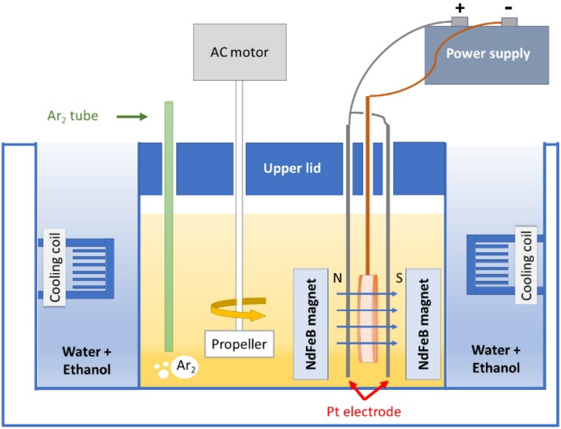
Figure 2.
Room-temperature XRD patterns of (a) the as-sintered sample and the sample with 1 h-coated CoFe and (b) the magnified pattern of 1 and 2 h CoFe-coated alloy.
Figure 2.
Room-temperature XRD patterns of (a) the as-sintered sample and the sample with 1 h-coated CoFe and (b) the magnified pattern of 1 and 2 h CoFe-coated alloy.
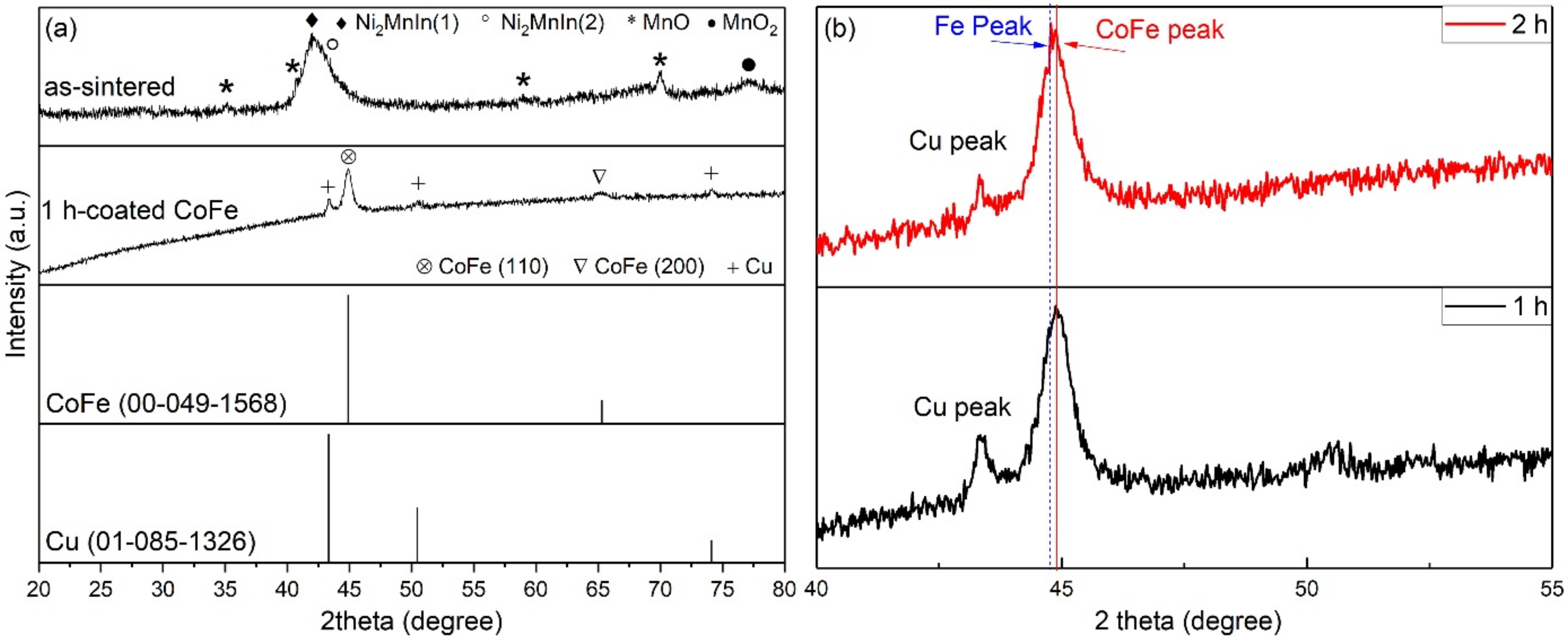
Figure 3.
SEM micrograph and EDS mapping of (a) 1 h CoFe-coated alloy and (b) Cu-coated followed by 1 h CoFe-coated alloy.
Figure 3.
SEM micrograph and EDS mapping of (a) 1 h CoFe-coated alloy and (b) Cu-coated followed by 1 h CoFe-coated alloy.

Figure 4.
Variation of the CoFe mass as a function of coating time.

Figure 5.
(a) The 2k magnification SEM images of the CoFe film with a coating time of 0.5, 1, 2, and 4 h; (b) the coating time dependence of average agglomeration size of the CoFe particle.
Figure 5.
(a) The 2k magnification SEM images of the CoFe film with a coating time of 0.5, 1, 2, and 4 h; (b) the coating time dependence of average agglomeration size of the CoFe particle.
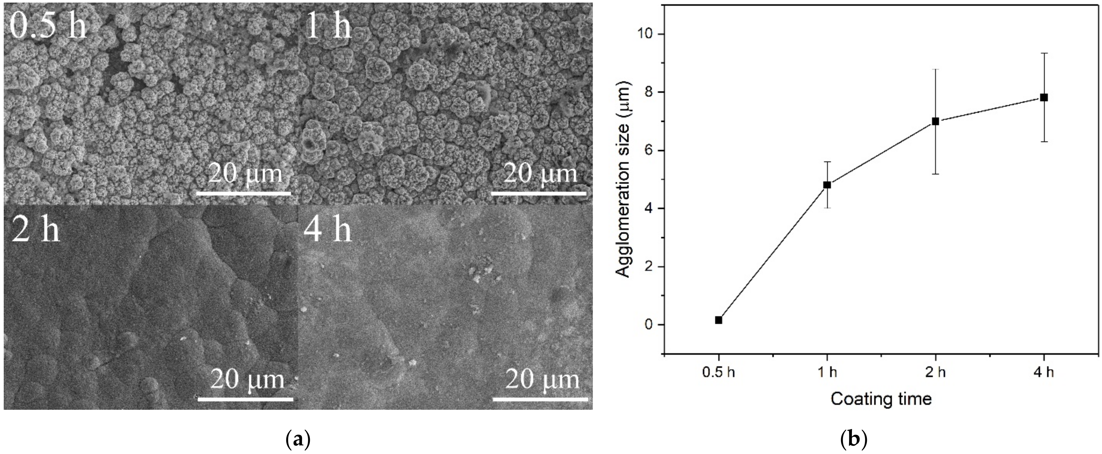
Figure 6.
Isothermal magnetization curves of CoFe film at (a) 298 K and (b) 253 to 333 K.
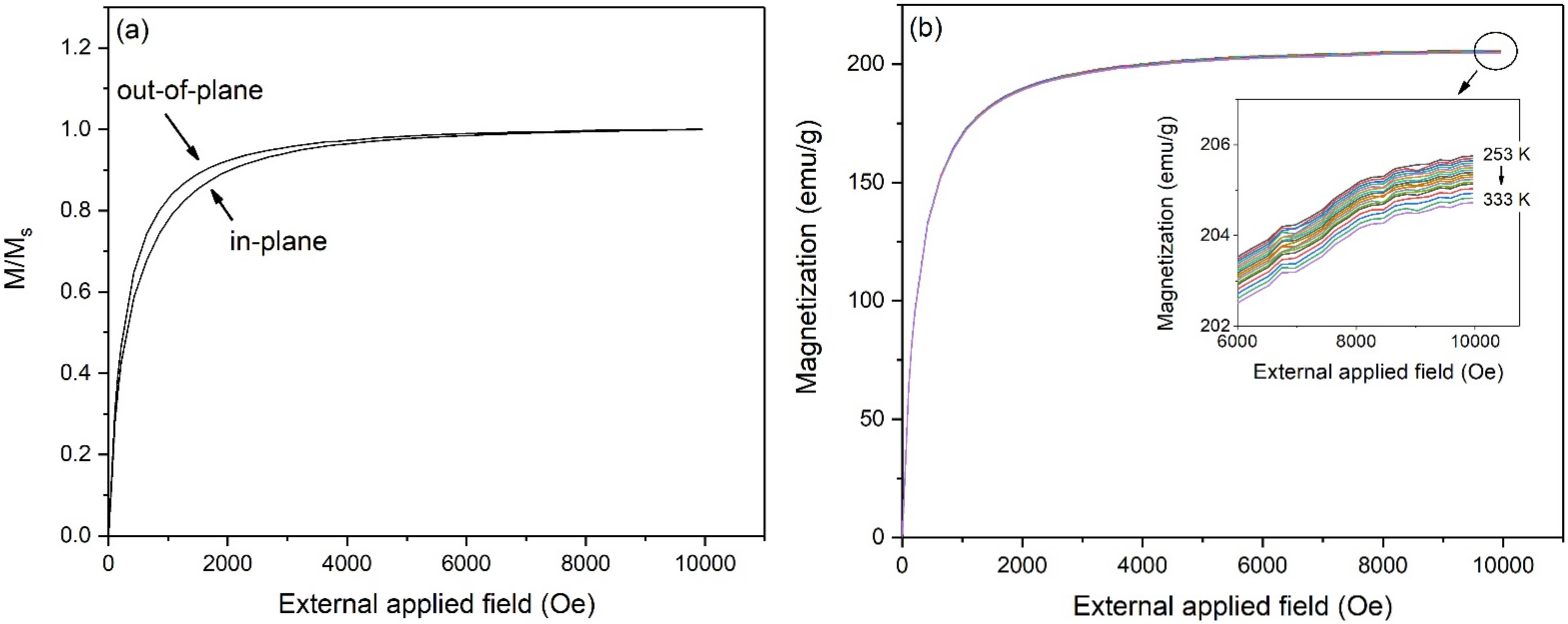
Figure 7.
Isothermal magnetization curves of (a) as-sintered Ni50Mn33In16Cr1 alloy and (b) 2 h CoFe-coated Ni50Mn33In16Cr1/Cu alloy at 253 to 333 K.
Figure 7.
Isothermal magnetization curves of (a) as-sintered Ni50Mn33In16Cr1 alloy and (b) 2 h CoFe-coated Ni50Mn33In16Cr1/Cu alloy at 253 to 333 K.
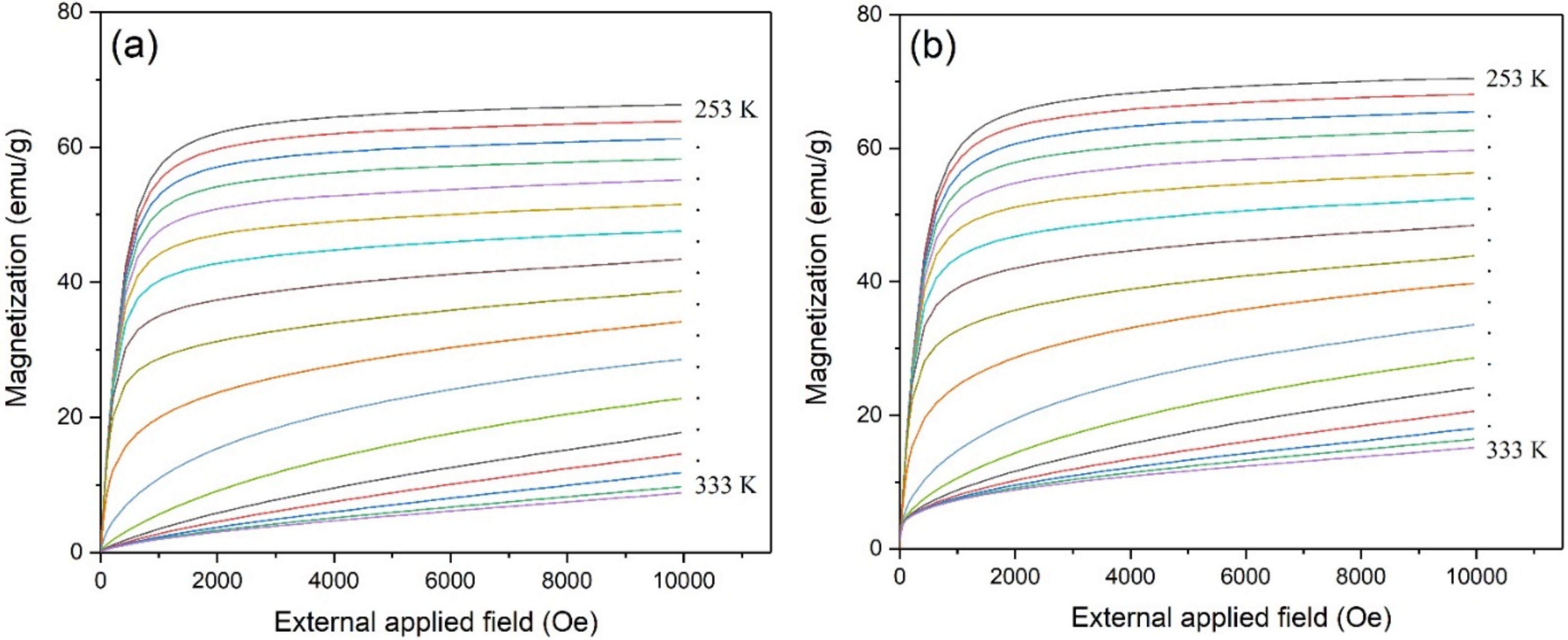
Figure 8.
Temperature dependence of magnetic entropy change of as-sintered Ni50Mn33In16Cr1 alloy and 2 h CoFe-coated Ni50Mn33In16Cr1/Cu under a magnetic field of 10 kOe.
Figure 8.
Temperature dependence of magnetic entropy change of as-sintered Ni50Mn33In16Cr1 alloy and 2 h CoFe-coated Ni50Mn33In16Cr1/Cu under a magnetic field of 10 kOe.

Figure 9.
Variation of temperature due to the changing of in-plane magnetic field 10 kOe of the CoFe-coated samples and as-sintered sample at the setpoint 300.5 K.
Figure 9.
Variation of temperature due to the changing of in-plane magnetic field 10 kOe of the CoFe-coated samples and as-sintered sample at the setpoint 300.5 K.
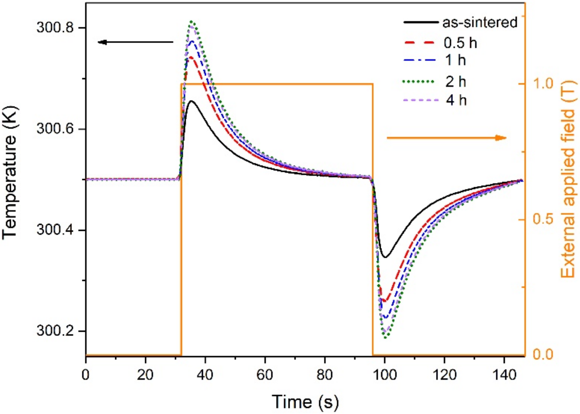
Figure 10.
Direct MCE measurement under (a,c) in-plane and (b,d) out-of-plane magnetic field of the CoFe-coated alloys compared to the as-sintered alloy.
Figure 10.
Direct MCE measurement under (a,c) in-plane and (b,d) out-of-plane magnetic field of the CoFe-coated alloys compared to the as-sintered alloy.
Publisher’s Note: MDPI stays neutral with regard to jurisdictional claims in published maps and institutional affiliations. |
© 2022 by the authors. Licensee MDPI, Basel, Switzerland. This article is an open access article distributed under the terms and conditions of the Creative Commons Attribution (CC BY) license (https://creativecommons.org/licenses/by/4.0/).
Share and Cite
MDPI and ACS Style
Lekkla, P.; Jantaratana, P.; Chotibhawaris, T. Magnetocaloric Effect in CoFe-Electroplated Ni50Mn33In16Cr1 Alloy. Metals 2022, 12, 2137. https://doi.org/10.3390/met12122137
AMA Style
Lekkla P, Jantaratana P, Chotibhawaris T. Magnetocaloric Effect in CoFe-Electroplated Ni50Mn33In16Cr1 Alloy. Metals. 2022; 12(12):2137. https://doi.org/10.3390/met12122137
Chicago/Turabian StyleLekkla, Peerapat, Pongsakorn Jantaratana, and Thanakrit Chotibhawaris. 2022. "Magnetocaloric Effect in CoFe-Electroplated Ni50Mn33In16Cr1 Alloy" Metals 12, no. 12: 2137. https://doi.org/10.3390/met12122137
Note that from the first issue of 2016, this journal uses article numbers instead of page numbers. See further details here.