
The Microstructure Formation in Slag Solidification at Continuous Casting Mold


School of Engineering and Innovation, The Open University, Walton Hall, Milton Keynes MK7 6AA, UK
*
Author to whom correspondence should be addressed.
Metals 2022, 12(4), 617; https://doi.org/10.3390/met12040617
Submission received: 9 March 2022
/
Revised: 28 March 2022
/
Accepted: 30 March 2022
/
Published: 2 April 2022
(This article belongs to the Special Issue Advances in Slag Metallurgy)
Abstract
:The microstructure of slag film solidified on the inner wall of mold in continuous casting of low carbon steel has been examined experimentally and analyzed theoretically. A puzzle for the crystallization sequence has been solved by this work, which is useful to guide the modification of slag microstructure in efficient casting of advanced steels. The experiments observed three crystalline bands, each containing an initial block-shaped crystal sub-band and late-developed dendrite sub-band. The grain size and morphology change monotonically across the crystalline layers to form a gradient structure. The reason for this is that the solute segregation causes considerable surging of viscosity and constitutional undercooling in the liquid phase. This is rarely seen in the casting of alloys and have not been pointed out previously in the casting of oxide mixtures.
1. Introduction
Slag film formed on the inner wall of a continuous casting mold plays several important roles. It protects the mold, provides lubrication, and controls horizontal heat transfer rate [1]. In the casting of advanced steels, the controllable microstructure formation in an albeit very thin slag film can be implemented to control the surface quality and mechanical properties of the casts [2,3]. In aiming at such functionality, it is crucial to understand the formation mechanisms of the microstructure in a slag film.
It is well-known that most slag film contains a crystalline layer and another amorphous layer [4,5,6]. However, the position and volume fraction of each layer is very different from one case to another. The amorphous layer, in some cases, is located on the mold side but in many other cases on the steel side. The thickness fraction of each layer is related to the chemical constitution of the slag, temperature, and processing duration, which has attracted significant research attention in the past several decades [7,8,9,10,11,12]. For the crystalline layer, the literature has mainly reported on the phase equilibrium and chemical constitution of the possible phases. There is a lack of comprehensive analysis of the microstructure and their formation sequence in the crystalline layer. This leaves two major puzzles: (1) Is the crystalline layer formed via crystallization of the amorphous layer or from the solidification of liquid directly? (2) What are the major differences between the slag solidification and alloy solidification? The aim of the present work was to address those two questions. The experiments were performed on a slag film obtained from an industrial production line in the casting of low carbon steel to enhance the practical applicability of the research. Solidification theory, diffusion-limited crystal growth, and segregation-related rheological property were implemented to understand the microstructure evolution. Improvement of the fundamental understanding of the microstructure formation in slag film is the first step to understand its microstructure evolution in more complicated situations, such as the cases when electric field and magnetic field are present in the continuous casting [13,14]. The knowledge about the microstructural control and modification in slag solidification is directly related to the quality of steels made by the continuous casting. The fraction and morphology of the crystalline phase, the amount of interface, and the thickness of the amorphous layer have a direct impact on the horizontal heat transfer and lubrication between the mold and steel skin [15,16]. This research contributed to the topic.
2. Materials and Methods
In the continuous casting of steel, the mold is made by copper with embedded channels to allow cooling water to flow inside and bring away the extra heat. Some mold flux is coated on the inner wall to form a slag film. The mold is driven to a constant vertical vibration to prevent the steel from sticking to the mold. Some liquid mold flux penetrates into the tiny gap between the steel and mold slag film to enhance lubrication and to compensate for the abrasive loss of the slag film. The sample of the slag film was taken by purposely lowering the level of liquid steel so that a piece of the slag film was peeled off from the inner wall of the mold. The chemical composition of the sample is listed in Table 1.
The appearance of an as-received sample is shown in Figure 1. The sample on the mold side looks opaque while on the steel side appears translucent. Many superficial surface cracks are visible on the mold-side surface. Some cracks were filled subsequently by the penetrated liquid slag and then solidified again, labelled as ‘F’ in Figure 1a. Both sides of the samples were grounded slightly to obtain a flat surface and then X-ray diffraction (XRD) patterns were obtained in order to characterize the mineralogical phases. Diffraction data were collected using a Siemens D5000 diffractometer (Bragg–Brentano geometry) to produce diffractograms from CuKa wavelengths (1.54 Å). Data collection was in 2θ range of 10–90° with a step size of 0.02° and a count time at each step of 1 s. DIFFRAC.EVA software created by Bruker Corp was used for phase identification. The files used for peak identification are (a) Cuspidine [17] and (b) Nepheline [18]. The accurate formula for nepheline is Na0.98 AlO4Si. The microstructure and element distribution in cross-section were studied by scanning electron microscopy (SEM) with energy dispersive spectroscopy (EDS) using Zeiss Supra 55VP FEG SEM manufactured by Carl Zeiss AG.
3. Results
Figure 2 shows a SEM image in backscatter mode from the cross-section of a sample. It consists of crystalline and amorphous layers with an obvious amorphous–crystalline interface, as is labelled with arrows. There is no noticeable microstructural feature in the amorphous region apart from the cracks. The image from the bottom to top indicates the direction from the mold side to steel side. The amorphous layer is on the steel side.
Figure 3 shows the X-ray diffraction (XRD) pattern from the surfaces of both the mold side and steel side of a sample, respectively. The mold side (black line) appears to be almost completely crystalline while the steel side (red line) is a mixture of amorphous and crystalline phases. Both cuspidine (Ca4Si2F2O7) and nepheline crystals were detected on the mold side of the slag film. The steel side is mainly amorphous but with a small quantity of cuspidine crystals, which appear to exist in a thin layer about several µm thickness.
Figure 4a is a SEM image of crystalline layer (mold side) of the slag film. It shows the laminate internal bands, which can be seen more clearly from Figure 4b. There are at least three bands, denoted as U, M and L for upper band, middle band and lower band in Figure 4a,b, respectively. A dendritic sub-band can be observed clearly in each band. It is possible that band M contains two bands because two layers of dendrites are noticed in Figure 4b. Each band has a sub-band containing block-shaped crystals and another sub-band formed by fine dendrite crystals. The structure of band U is shown in Figure 4c. The dendrites grow from the mold side towards the steel side of the sample. The block-shaped crystals are thicker than that of dendrite arms but without clear indication of surface symmetry. Furthermore, the dendrites show tip-split, secondary, and third arms with preferred growth directions.
Figure 5 shows the higher magnification images taken from the sub-bands containing block-shaped crystals at the three bands in the crystalline layer, where Figure 5a is from the upper band, Figure 5b for the middle band and Figure 5c for the lower band. It can be seen from Figure 5a–c that the microstructures tend to be finer, and the surfaces of the block-shaped crystals become more and more fractal. Many flat interfaces and facets are observable in crystals in Figure 5a. However, almost no flat interfaces and facets can be found in Figure 5c.
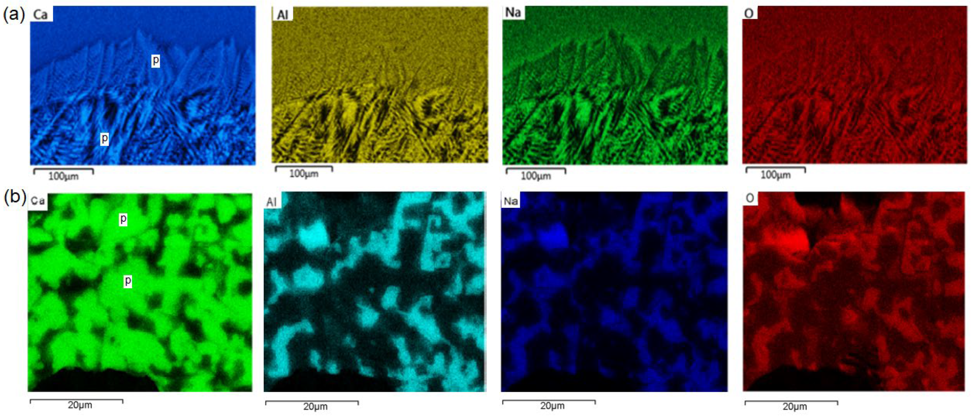
For further characterization of the chemical constituents in the slag film, EDS map analysis was carried out on various parts in the slag sample. Figure 6 presents the EDS maps for the distribution of Ca, Al, Na, O in (a) the upper band and crystalline–amorphous interfacial region and (b) the block-shaped sub-band in the lower band region, where the brighter color indicates the higher concentration of the elements. The EDS maps for several other elements have also been examined but not presented here. For example, it is found that the Si is distributed almost evenly across the sample and Fe is present only in a few isolated small spherical particles. The latter indicates that some small Fe droplets are entrapped in the slag film. Figure 6 shows that the primary crystals (labeled with ‘p’) are rich in Ca and poor in Al, Na, and O. According to the XRD results reported in Figure 3, the primary crystals are cuspidine phase (being rich in Ca) while the areas between the primary crystals contain nepheline phase (being rich in Al and Na).
4. Theoretical Consideration and Discussion
4.1. Microstructure Formation Sequences
There is no direct evidence to prove whether the crystalline phase in slag film is formed either in the solidification or via the crystallization of an amorphous phase. The latter means that the liquid is firstly quenched to an amorphous solid and then undergoes a crystallization. However, the morphology of crystalline phases provides some clues toward the analysis of the microstructure formation sequence [19]. Following is our theoretical analysis for this.
Suppose that the liquid slag was firstly solidified and formed an amorphous solid on the inner wall of the mold, crystalline in this case could only form via crystallization of the amorphous phase. Crystallization of the amorphous solid is controlled by solute diffusion. The diffusivity is described by Arrhenius equation and expressed as [20]
where D is the diffusivity. is the pre-exponential coefficient determined by microscale parameters such as atoms’ vibration frequency and the space distance between atoms. is the activation energy, R is the gas constant and T is the local temperature. Equation (1) indicates a higher diffusivity in the higher temperature area. Therefore, the crystallization should have started from the higher temperature area and the dendrite tips should point to the lower temperature area, which contrasts with the observations reported in Figure 4. Therefore, it is suggested that the crystalline is formed directly in solidification.
Figure 4 shows several bands in the crystalline layer and each band containing sub-bands with block and dendrite morphological crystals. The bands are formed layer-by-layer in an additive manner. The first layer attaching on the mold wall is coated by cold sprayed mold powder before casting. The microstructure in this layer is quite complicated and with lots of porosity. The subsequent layers were formed from the solidification of liquid slag that penetrated through the gap between the solidified slag film and steel. Because the temperature from the water-cooled mold to liquid steel is increasing, the diffusivity is bigger in the higher temperature area. The microstructure is coarser in the higher temperature band. This agrees with the experimental observations in Figure 5.
Figure 2 shows both the crystalline layer and amorphous layer in the slag film. The amorphous layer is formed when the sample is taken out of the casting mold. The remaining lubricating liquid slag on the surface of solid slag film is suddenly moved from 1600 K in mold to ambient conditions and quenches into an amorphous state.
According to Figure 4c, all the dendrites in the sub-bands grow in the direction from low temperature mold side to the high temperature steel side. This means that the crystals nucleate initially in a low temperature region and grow toward the high temperature region. The thermodynamic driving force for homogeneous crystal nucleation in liquid is approximated as [21]
where is the thermodynamic driving force for nucleation, is latent heat, is melting temperature, and T the local temperature. The crystal nucleation rate in the low temperature region is larger than that in the high temperature area. Thus, the dendrites are pointing towards the hotter regions as shown in Figure 4c. In fact, this dendritic growth pattern is similar to those observed in the ingot casting of alloys.
4.2. Formation of Sub-Bands
The crystalline layer contains at least three bands and each band contains two sub-bands with peculiar morphologies. Figure 4c shows the two distinctive sub-bands in the upper band. The primary crystals are cuspidine phase according to the analysis of elemental distribution profiles shown in Figure 6. The block-shaped crystals are nucleated firstly followed by the dendritic crystals [22]. Generally, the crystal morphology is mostly determined by the crystal growth process after nucleation. The crystal growth can be controlled by elemental diffusion in melt and phase transition rate at the interface. In the case where crystal growth is controlled by the phase transition rate at the interface rather than the diffusion, as is described by the Scheil–Gulliver equation, the crystal morphology is likely to be block-shaped. Therefore, the formation of block-shaped crystals is indicative of a solute rich liquid with high elemental diffusion [23].
Cuspidine absorbs Ca and F and expels Al and Na in the liquid slag. The remaining liquid becomes poor in Ca and F and richer in Na and Al as the cuspidine continues to grow in block-shaped morphology. The reduction of either F or CaF2 results in a drastic increase in the viscosity of the remaining liquid [24]. Moreover, the increase of Al2O3 also causes the significant surge in viscosity [25]. The solute diffusivity in the liquid phase is inversely proportional to the viscosity according to the Stokes–Einstein equation as
where is dynamic viscosity at temperature . The drastic increase of viscosity due to solute segregation causes a significant reduction of diffusivity. The low solute composition of Ca and F and low diffusivity triggers the diffusion-limited growth [26], which facilitates the dendrites’ formation. The segregation-induced viscosity surge and diffusivity plunge is the major difference between the solidifications in slags and metals.
Interestingly, the pore size becomes larger along each band from the bottom of the block-shaped sub-band to the dendrite sub-band. These pores are formed due to volume shrinkage associated with crystallization and insufficient refilling of liquid. Viscosity has been increased drastically by the solute segregation during crystal growth, as has been discussed earlier in the present work, which leads to the formation of large pores. In the upper band, however, the effect of high temperature compensates for some of the segregation-induced viscosity. The high fluidity of the liquid phase in the upper band due to high temperature is able to refill the shrinkage caused by crystallization and hence almost no pores were seen. It is also possible that some gas bubbles were entrapped in the fast-cooled layer unable to escape due to fast cooling.
After a substantial amount of Al2O3 is expelled due to the growth of cuspidine into molten oxides, not only the viscosity but also the melting temperature is increased [27]. Such thick and constitutionally undercooled melt can freeze to form glass. This explains why some regions between cuspidine crystals contain not only nepheline but also residual glass.
4.3. Grain Size and Surface Instability
Figure 5 shows finer grains and more curved crystal interface for the block-shaped crystals from the upper band to the lower band via the middle band. This is because of temperature on crystal growth. The lower band adjacent to the mold wall experiences lower temperatures due to heat extraction from the mold wall. This allows the liquid slag to achieve higher undercooling when deposited on the colder surface. The nucleation rate for homogeneous system is [23]
where is the thermodynamic driving force defined in Equation (2) The lower local temperature corresponds to a higher nucleation rate. The higher undercooling in liquid also affects the temperature gradient of the liquid adjacent to the crystal–liquid interface, the steeper temperature gradient ahead of the crystal–liquid interface causes severe interface instabilities. This has been described by the Mullins–Sekerka instability equation [28]. More curved interfaces can form in such cases. On the other hand, the lower diffusivity in the lower temperature area slows down the interface minimization [29]. Both these effects result in formation of finer and somewhat globular cuspidine crystals observed in the lower band, shown in Figure 5c.
5. Conclusions
The solidification of slag film on the inner wall of the mold in the continuous casting of steel has been investigated experimentally and analyzed theoretically. The following insights were achieved.
- The microstructure contains a crystalline layer and an amorphous layer. The crystalline layer contains three bands, with each band containing two sub-bands of blocky and dendritic morphologies, respectively;
- The crystalline bands are formed directly from solidification instead of from the crystallization of the amorphous state. This clarifies a major puzzle in slag solidification. The result was achieved according to the analysis of crystal morphology and growth direction;
- The solute segregation in liquid slag during cuspidine crystal growth causes a considerable surge of viscosity. This is one of the major reasons for porosity formation and glass formation. The segregation of Al can cause an increase in both the melting temperature and viscosity of liquid slag. This increases constitutional undercooling. The retained liquid can hence be frozen into an amorphous state;
- The segregation-induced increase of viscosity reduces diffusivity, which contributes to the block-to-dendrite transformation.
Author Contributions
Conceptualization, R.Q.; Sample preparation and characterization, A.G.B.; Analysis, A.G.B. and R.Q.; writing—original draft preparation, A.G.B.; writing—review and editing, R.Q.; funding acquisition, R.Q. All authors have read and agreed to the published version of the manuscript.
Funding
The work has been funded by the European Commission’s Research Fund for Coal and Steel under Grant Agreement No 847269 and from the Engineering and Physical Sciences Research Council at UK under Grant Agreement No EP/R029598/1.
Institutional Review Board Statement
Not applicable.
Informed Consent Statement
Not applicable.
Data Availability Statement
Data are contained within the article.
Conflicts of Interest
The authors declare no conflict of interest.
References
- Mills, K.C.; Fox, A.B. The role of mould fluxes in continuous casting-so simple yet so complex. ISIJ Int. 2003, 43, 1479–1486. [Google Scholar] [CrossRef]
- Shu, Q.F.; Li, Q.Q.; Medeiros, S.L.S.; Klug, J.L. Development of non-reactive f-free mold fluxes for high aluminum steels: Non-isothermal crystallization kinetics for devitrification. Metall. Mater. Trans. B 2020, 51, 1169–1180. [Google Scholar] [CrossRef] [Green Version]
- Wang, Z.; Huang, S.H.; Wen, G.G.; Jiang, W.B.; Tang, P. Computational insight into the thermal conductivity of CaO-SiO2-Al2O3-MgO-Na2O melts. Metall. Mater. Trans. B 2020, 51, 2391–2399. [Google Scholar] [CrossRef]
- Hooli, P. Study on the Layers in the Film Originating from the Casting Powder between Steel Shell and Mould and Associated Phenomena in Continuous Casting of STAINLESS steel. Ph.D. Thesis, Helsinki University of Technology, Helsinki, Finland, 2007. [Google Scholar]
- Wang, W.L.; Yu, J.; Zhou, L.J.; Wu, Z.Y.; Li, H. Optimization of mold flux for the continuous casting of Cr-contained steels. Metall. Mater. Trans. B 2018, 49, 1580–1587. [Google Scholar] [CrossRef]
- Yang, C.L.; Wen, G.H.; Tang, P.; Xi, C.C.; Sun, Q.H. Quantification of crystalline fraction of solid slag film using X-ray powder diffraction. Powder Diffr. 2016, 31, 40–51. [Google Scholar] [CrossRef]
- Watanabe, T.; Hashimoto, H.; Hayashi, M.; Nagata, K. Effect of alkali oxides on crystallization in CaO-SiO2-CaF2 glasses. ISIJ Int. 2008, 48, 925–933. [Google Scholar] [CrossRef] [Green Version]
- Susa, M.; Kubota, S.; Hayashi, M.; Mills, K.C. Thermal conductivity and structure of alkali silicate melts containing fluorides. Ironmak. Steelmak. 2001, 28, 390–395. [Google Scholar] [CrossRef]
- Wang, Z.J.; Sohn, I. Experimental determination of phase equilibria in the CaO-BaO-SiO2-12 mol pct. Al2O3-13 mol pct. MgO system at 1573 K and 1623 K. J. Am. Ceram. Soc. 2019, 102, 5632–5644. [Google Scholar] [CrossRef]
- Hayashi, M.; Watanabe, T.; Nakada, H.; Nagata, K. Effect of Na2O on crystallization of mould fluxes for continuous casting of steel. ISIJ Int. 2006, 46, 1805–1809. [Google Scholar] [CrossRef] [Green Version]
- Yamauchi, A.; Sorimachi, K.; Yamauchi, T. Effect of solidus temperature and crystalline phase of mould flux on heat transfer in continuous casting mould. Ironmak. Steelmak. 2002, 29, 203–207. [Google Scholar] [CrossRef]
- Susa, M.; Kushimoto, A.; Toyota, H.; Hayashi, M.; Endo, R.; Kobayashi, Y. Effects of both crystallisation and iron oxides on the radiative heat transfer in mould fluxes. ISIJ Int. 2009, 49, 1722–1729. [Google Scholar] [CrossRef]
- Huang, X.C.; Duan, Y.R.; Liu, Z.Q.; Li, B.K.; Wang, F. Role of electrode rotation on improvement of metal pool profile in electroslag remelting process. Metals 2021, 11, 1675. [Google Scholar] [CrossRef]
- Persson, E.S.; Brorson, S.; Mitchell, A.; Jonsson, P.G. Impact of solidification on inclusion morphology in ESR and PESR remelted martensitic stainless steel ingots. Metals 2021, 11, 408. [Google Scholar] [CrossRef]
- Shibata, H.; Emi, T.; Waseda, Y.; Kondo, K.; Ohta, H.; Nakajima, K. Thermal diffusivities of continuous casting mold fluxes for steel in the glassy and crystalline states. J. Iron Steel Inst. Jpn. 1996, 82, 504–508. [Google Scholar] [CrossRef] [Green Version]
- Guo, J.; Seo, M.D.; Shi, C.B.; Cho, J.W.; Kim, S.H. Control of crystal morphology for mold flux during high-aluminum AHSS continuous casting process. Metall. Mater. Trans. 2016, 47B, 2211–2221. [Google Scholar] [CrossRef] [Green Version]
- Saburi, S.; Kawahara, A.; Henmi, C.; Kusachi, I.; Kihara, K. The refinement of the crystal structure of cuspidine. Mineral. Mag. 1977, 8, 286–298. [Google Scholar] [CrossRef] [Green Version]
- Vulić, P.; Kahlenberg, V.; Konzett, J. On the existence of a Na-deficient monoclinic trinepheline with composition Na7.85Al7.85Si8.15O32. Am. Mineral. 2008, 93, 1072–1079. [Google Scholar] [CrossRef]
- Castillejos E, A.H.; Tania, M.; Flores, F. Characterization of roughness, porosity and thermal resistances of continuous casting mold slag layers devitrified and crystallized in laboratory. Metall. Mater. Trans. B 2019, 50, 2436–2453. [Google Scholar] [CrossRef]
- Arrhenius, S.A. Über die dissociationswärme und den einfluss der temperatur auf den dissociationsgrad der elektrolyte. Z. Phys. Chem. 1889, 4, 96–116. [Google Scholar] [CrossRef] [Green Version]
- Qin, R.S.; Zhou, B.L. Effect of electric current pulses on grain size in castings. Int. J. Non-Equilib. Proc. 1998, 11, 77–86. [Google Scholar]
- Hooli, P.O. Mould flux film between mould and steel shell. Ironmak. Steelmak. 2002, 29, 293–296. [Google Scholar] [CrossRef]
- Qin, R.S.; Wallach, E.R.; Thomson, R.C. A phase-field model for the solidification of multicomponent and multiphase alloys. J. Crys. Growth 2005, 279, 163–169. [Google Scholar] [CrossRef]
- Wang, X.J.; Jin, H.B.; Zhu, L.G.; Xu, Y.; Liu, R.; Piao, Z.L.; Qu, S. Effect of CaF2 on the viscosity and microstructure of CaO-SiO2-Al2O3 based continuous casting mold flux. Metals 2019, 9, 871. [Google Scholar] [CrossRef] [Green Version]
- Bian, L.T.; Gao, Y.H. Influence of Al2O3, CaO/SiO2, and B2O3 on viscous behavior of high alumina and medium titania blast furnace slag. J. Chem. 2017, 2017, 6895928. [Google Scholar] [CrossRef] [Green Version]
- Witten, T.A.; Sander, L.M. Diffusion-limited aggregation, a kinetic critical phenomenon Phys. Rev. Lett. 1981, 47, 1400–1403. [Google Scholar] [CrossRef]
- Liu, H.; Qin, Y.L.; Yang, Y.H.; Zhang, Q.Y.; Deng, N.Y. Influence of Al2O3 content on the melting and fluidity of blast furnace type slag with low TiO2 content. J. Chem. 2018, 2018, 9502304. [Google Scholar] [CrossRef]
- Mullins, W.W.; Sekerka, R.F. Stability of a planar interface during solidification of a dilute binary alloy. J. Appl. Phys. 1964, 35, 444. [Google Scholar] [CrossRef]
- Qin, R.S. Suppression of the surface roughness and fluctuation frequency by electric method. Mater. Today Commun. 2021, 28, 102512. [Google Scholar] [CrossRef]
Figure 1.
Photos of a sample (a) on mold side and (b) on steel side.
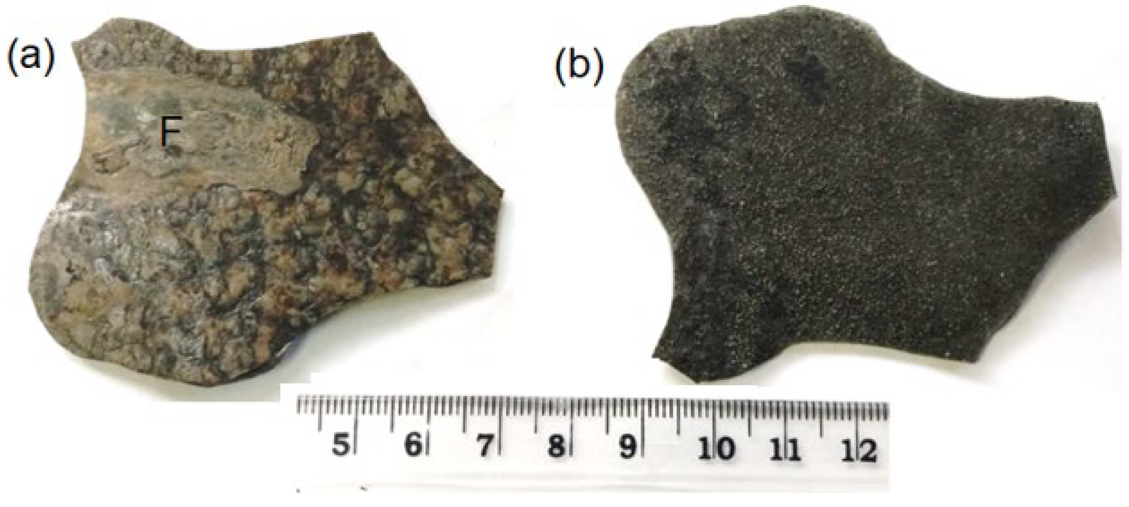
Figure 2.
SEM image shows the amorphous layer and crystalline layer.
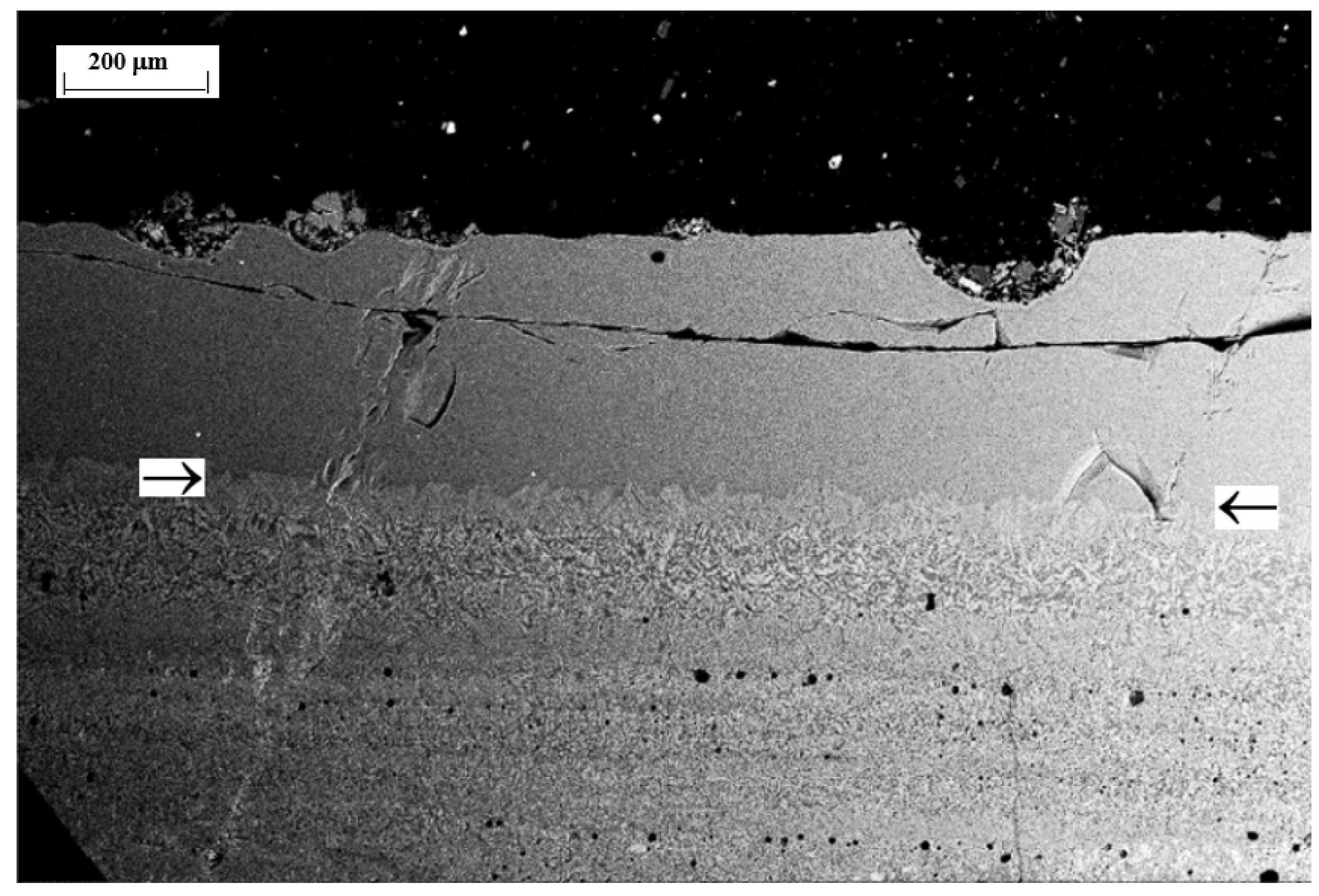
Figure 3.
X-ray diffraction (CuKα = 1.54 Å) pattern measured on both mold side and steel side of a slag film. Cuspidine is in monoclinic structure and nepheline is in hexagonal P61 structure.
Figure 3.
X-ray diffraction (CuKα = 1.54 Å) pattern measured on both mold side and steel side of a slag film. Cuspidine is in monoclinic structure and nepheline is in hexagonal P61 structure.

Figure 4.
(a) SEM image and (b) optical microscope image show the band structure inside the crystalline layer, where U, M and L indicate the upper band, middle band and lower band; (c) SEM image of upper band shows two sub-bands of block-shaped and dendrite-shaped crystals.
Figure 4.
(a) SEM image and (b) optical microscope image show the band structure inside the crystalline layer, where U, M and L indicate the upper band, middle band and lower band; (c) SEM image of upper band shows two sub-bands of block-shaped and dendrite-shaped crystals.

Figure 5.
SEM images taken from the sub-bands of block-shaped crystals at (a) upper band; (b) middle band; and (c) lower band, showing the finer microstructures and more fractal interfaces from (a–c).
Figure 5.
SEM images taken from the sub-bands of block-shaped crystals at (a) upper band; (b) middle band; and (c) lower band, showing the finer microstructures and more fractal interfaces from (a–c).

Figure 6.
EDS maps reveal the configuration of Ca, Al, Na and O elements in (a) the upper band and crystalline–amorphous interfacial region; and (b) block-shaped sub-band in lower band. The brighter color indicates the higher concentration of the elements.
Figure 6.
EDS maps reveal the configuration of Ca, Al, Na and O elements in (a) the upper band and crystalline–amorphous interfacial region; and (b) block-shaped sub-band in lower band. The brighter color indicates the higher concentration of the elements.

Table 1.
Chemical compositions of the slag film in wt.%.
| SiO2 | CaO | Na2O | F | Al2O3 | MgO | C |
|---|---|---|---|---|---|---|
| 38.44 | 35.74 | 12.9 | 9.4 | 2.5 | <1 | balance |
Publisher’s Note: MDPI stays neutral with regard to jurisdictional claims in published maps and institutional affiliations. |
© 2022 by the authors. Licensee MDPI, Basel, Switzerland. This article is an open access article distributed under the terms and conditions of the Creative Commons Attribution (CC BY) license (https://creativecommons.org/licenses/by/4.0/).
Share and Cite
MDPI and ACS Style
Bhagurkar, A.G.; Qin, R. The Microstructure Formation in Slag Solidification at Continuous Casting Mold. Metals 2022, 12, 617. https://doi.org/10.3390/met12040617
AMA Style
Bhagurkar AG, Qin R. The Microstructure Formation in Slag Solidification at Continuous Casting Mold. Metals. 2022; 12(4):617. https://doi.org/10.3390/met12040617
Chicago/Turabian StyleBhagurkar, Ashutosh G., and Rongshan Qin. 2022. "The Microstructure Formation in Slag Solidification at Continuous Casting Mold" Metals 12, no. 4: 617. https://doi.org/10.3390/met12040617
Note that from the first issue of 2016, this journal uses article numbers instead of page numbers. See further details here.