
Machinability Analysis of Finish-Turning Operations for Ti6Al4V Tubes Fabricated by Selective Laser Melting
by
 , and
, and
Guangxian Li
1,2, 
Rizwan Abdul Rahman Rashid
2,3,
Songlin Ding
1,2,
Shoujin Sun
2,4 and
Suresh Palanisamy
2,3,* 1
School of Engineering, RMIT University, Melbourne, VIC 3000, Australia
2
DMTC Ltd., Hawthorn, VIC 3122, Australia
3
School of Engineering, Swinburne University of Technology, Hawthorn, VIC 3122, Australia
4
School of Engineering and Built Environment, Griffith University, Gold Coast, QLD 4222, Australia
*
Author to whom correspondence should be addressed.
Metals 2022, 12(5), 806; https://doi.org/10.3390/met12050806
Submission received: 3 April 2022
/
Revised: 28 April 2022
/
Accepted: 4 May 2022
/
Published: 7 May 2022
(This article belongs to the Special Issue Advancements in Machining Technologies of Titanium-Based Alloys)
Abstract
:With the advent of additive manufacturing as an advanced technology for the fabrication of titanium components, there is a pressing need to investigate the machinability of parts produced using these techniques compared to components made with conventional wrought methodologies. The motivation for this study was to investigate the influences of machining parameters, especially cutting depth, on the machinability of selective laser melted (SLMed) Ti6Al4V tubes, by analyzing the cutting responses, including cutting forces, machined surface roughness and tool wear at varying cutting parameters. Generally, it can be inferred that specific cutting tools used to machine wrought titanium components can also be used for SLMed parts when carrying out finish-machining operations. Cutting forces in the machining of SLMed workpieces could be up to 70% higher than those in machining the wrought counterparts. In contrast, the tool-wear analysis correspondingly showed larger tool-workpiece engagement area on the tool rake face for tools used for machining wrought parts. Adhesion on the cutting edge in the form of built-up edge and attrition of the tool surface were found to be the two most dominant tool-wear mechanisms, and the oxidation condition of the tool surface in machining SLMed parts was more severe (about 8% and 21%). Vibration analysis was also carried out, but no significant difference between the SLMed and wrought workpieces was observed, and the quality of the machined surface was similar.
1. Introduction
Titanium alloys have been widely used in industries, such as aerospace, automobile and biomedical engineering, due to their excellent physical and mechanical properties [1]. In order to obtain components with specific contours, a huge number of redundant workpiece materials must be removed from the stock. Additionally, in the cutting processes, the high yield strength and low thermal conductivity of titanium alloys always cause larger cutting force and higher cutting temperature in the cutting zone, which accelerate the wear rate of the cutting tools and eventually limit the machining efficiency [2]. With the development of additive manufacturing (AM), some powder bed fusion (PBF) techniques are currently widely used in the fabrication of metallic components. Specifically, selective laser melting (SLM) is the most widely used technique in the production of parts made from metals or metal matrix composites [3,4,5]; direct melting laser sintering (DMLS), a special instantization of selective laser sintering, can achieve nearly full density of the workpiece material [4]; and electron beam melting (EBM), which uses an electron beam as the heat source [5], can result in higher manufacturing speed. In such AM processes, the powder of the workpiece materials is melted and built layer-by-layer, based on the contour of the three-dimensional model of the component [6]. Using AM, near-to-shape parts can be obtained without significant additional shaping processes, including conventional cutting, such as turning, milling or drilling. This increases production efficiency in manufacturing parts with complex contours, and meets the demand for green production.
However, the parts produced by AM cannot be used or assembled directly. This is because the surface integrity of SLMed parts is poor, specifically, the surface roughness, hardness and residual stress of the SLMed surface are even higher than the wrought material [7]. Therefore, the surface material of the parts should be removed by conventional cutting processes in order to obtain acceptable surface finish. However, the mechanical properties of the SLMed titanium alloys are different from those of wrought titanium alloy, due to the unique microstructure of the workpiece caused by the rapid melting–resolidification during the AM processes. As shown in Table 1, it can be seen that the hardness, yield strength and ultimate tensile strength of SLMed Ti6Al4V are increased compared with those of the wrought material. Specifically, the hardness of Ti6Al4V fabricated by laser additive manufacturing increased 30–45% compared with the hardness of wrought material; the yield strength experienced increased from 200 MPa to 320 MPa. These enhanced mechanical properties influenced the elastic–plastic deformation of the workpiece material during the cutting process, causing variations in cutting forces, temperatures and condition of tool wear in the cutting processes, which eventually affected surface roughness and residual stress in the machined parts. Furthermore, the micro-defects in the AMed Ti6Al4V could also affect the quality of machined surface. Specifically, the grains of the alloy are coarse and pores are always found within the structure, which could also reduce the surface integrity after cutting [1,8]. Therefore, it is necessary to investigate the machinability of SLMed titanium alloys to ensure the high quality of the machined surface.
Experimental and theoretical works have been carried out to investigate the cutting forces and surface integrity of the SLMed titanium alloys. Shunmugavel et al. [12] compared the machinability of wrought and SLMed Ti6Al4V by analyzing the cutting force and surface roughness. It was found that the cutting forces were larger when machining the SLMed Ti6Al4V because of the higher yield strength. The roughness of the machined surfaces of the SLMed parts was lower, the reason being that higher hardness reduced the ductility, and thus limited lateral plastic flow of the peaks on the machined surface. In the study of Kallel et al. [13], the machinability of Ti6Al4V fabricated by laser metal deposition (LMD) was investigated. A similar trend in the cutting force was found; there was a 10–40% increment of force when cutting the LMDed materials. However, the roughness of the machined surfaces of LMDed materials was higher than that of the wrought material due to the more significant ploughing and rubbing effects. The machinability of wrought and EBMed titanium alloy in micro-milling was investigated by Hojati et al. [14]. Specific energy and burr formation during the cutting process were analyzed. The results showed that, due to the size effect, the specific energy in cutting the EBMed material was 5–15% higher when the chip thickness was smaller than 7.4 μm. The burr formation was continuous on the wrought material part, but in contrast, the burr formation on the EBMed part was a discontinuous irregular structure of the printed phase. Furthermore, more burr was formed on the EBMed parts in spite of the higher hardness. Bruschi et al. [15] conducted a series of turning experiments and sliding tests to investigate the wear behavior of SLMed Ti6Al4V for biomedical purposes. It was found that the microhardness and residual stress of the machined surface of SLMed Ti6Al4V was larger than those of the wrought material with cryogenic coolant, while the roughness of the machined surfaces of the two workpiece materials were similar. The results of sliding tests of the SLMed material showed that the wear behavior changed from abrasion-dominant to adhesion-dominant when the cutting conditions changed from dry cutting to cryogenic coolant.
Tool wear is the main factor in evaluation of machinability, since the condition of tool wear directly influences the cutting force and quality of a machined surface. Adhesive-abrasive wear is the dominant mechanism in the machining of titanium alloys, due to the high cutting temperature and severe abrasion at the tool/chip and tool/workpiece interfaces, and this process is mainly influenced by the selection of cutting parameters [16]. As for the machining of AMed Ti alloys, the improved mechanical properties could influence the wear of cutting tools. For example, in the study of Al-Rubaie et al. [17], the flank wear of the tools in the machining of SLMed Ti6Al4V was higher than that during machining of the wrought workpiece, and the phenomenon was attributed to the higher hardness of the SLMed workpiece material. Besides the influence of mechanical properties, the microstructure of the workpiece could be another factor that affects the development of tool wear. Specifically, the types, size and orientation of the grains and their distribution change the local properties of the workpiece, which eventually influence the conditions of tool wear [18,19]. In the research of Lizzul et al. [20], the influence of anisotropy induced by additive manufacturing on tool wear was investigated. Experiments were conducted by milling the Ti6Al4V blocks, which were fabricated by laser powder bed fusion (LPBF), in four build-up orientations: 0, 36, 72 and 90. The results showed that the tool life decreased gradually to 40% when the inclination angle of the layer was increased from 0 to 90. This was because the angle between the orientation of α grain boundary (αGB) layers and cutting direction increased, which prevented the initiation of workpiece material and formation of the chip flow.
To limit the development of tool wear caused by high temperature and severe friction in the machining of hard-to-machine materials, alternative cooling methods, such as cryogenic cooling and minimum quantity lubrication (MQL), are used to provide lubrication and reduce the temperature at tool/chip interface. The performance of cryogenic cooling has been investigated comprehensively in the cutting of hard-to-machine materials. Generally, it was found that adhesive wear can be significantly reduce by applying cryogenic cooling in the machining of titanium alloy, nickel-based superalloy and titanium/CFRP stack [21,22,23]. A similar phenomenon can be found in the machining of AMed Ti alloys with the application of cryogenic conditions. Bordin et al. [24] analyzed the tool wear in turning EBMed Ti6Al4V with cryogenic coolant. It was found that adhesion was the dominant wear mode on the tool rake face, and the crater wear was reduced by applying cryogenic coolant, due to the reserve of the adhesive layer as well as the reduced tool/chip contact length. Additionally, the preserve of the adhesion prevented abrasion on the cutting edge and flank faces, which limited the development of flank wear and blunting of the cutting edge. Sartori et al. [25] further investigated the development of tool wear when cutting different Ti6Al4V materials in dry conditions and cryogenic conditions. The workpieces were fabricated by wrought, EBM, DMLS and heat-treated DMLS, respectively. By analyzing the worn surfaces of the cutting tools, the most severe crater wear was found on the tool used in the dry cutting of workpieces fabricated by DMLS, because they had the highest hardness and lowest thermal conductivity. It was found that depth of crater wear could be reduced to 58% in dry cutting by applying cryogenic coolant. Compared with cryogenic cooling, which reduced the cutting temperature significantly, the application of MQL is effective in reducing the friction at tool/chip and tool/workpiece interfaces [26]. Khaliq et al. [27] investigated the wear of cutting tools in the micro-milling of SLMed titanium alloy under the conditions of dry cutting and MQL. The application of MQL was shown to reduce 27% of the flank wear and 26% of the wear of tool radius compared with the wear condition with dry cutting. Adhesive wear was still severe under both cutting conditions, which removed the surface of the cutting tool, reduced the hardness of tool surface and eventually led to the failure of the cutting edge.
Although there has been some research to investigate the machinability of SLMed Ti workpieces, there is little to no information on the effect of various cutting parameters such as cutting speed, feed rate, and cutting depth on the cutting force, surface roughness, and tool wear when machining AM-fabricated titanium tubes. These hollow tubes show a considerably different machining response in comparison with solid bulk parts. In addition, if these thin structures are not properly supported during machining, the tool performance will be further reduced, along with the quality of the finished parts. Therefore, in this study, the machinability of titanium tubes fabricated using SLM was investigated and compared with the machinability of wrought counterparts.
2. Experimental Setup
2.1. Preparation of Workpiece Material
The workpiece materials used in this research were Ti6Al4V tubes fabricated by conventional methods (wrought) and SLM respectively. The SLMed tube was produced using SLM250HL made by SLM Solutions GmbH using gas-atomized spherical powder supplied by TLS Technik GmbH & Co. The powder particle size distribution was characterized by D10 = 25.96 μm, D50 = 40.05 μm and D90 = 54.03 μm. The tube was fabricated so that the orientation of the axis of the tube was parallel to the build direction. The AM processing parameters used to fabricate the tube in this study were laser power P = 175 W, laser scanning v = 710 mm/s, hatch spacing h = 120 μm, layer thickness t = 30 μm and laser focal offset = 2 mm. The dimensions of the workpiece were 150 mm in length, 50 mm in diameter and 3 mm in thickness, as shown in Figure 1. The Vickers hardness of the SLMed Ti6Al4V was measured at 412 ± 12 HV, and the wrought workpiece was 357 ± 16 HV.
2.2. Turning Experiments
Turning experiments were carried out to investigate the machinability of wrought and SLMed Ti tube workpieces when machined using different cutting parameters. As shown in Figure 2a, the experiment was conducted on a CNC lathe (OKUMA GENOS L200E-M) under dry cutting conditions, and the WC turning inserts CNMG120408-MF1 890, SECO (Figure 2b) were used as the cutting tool. The geometry of the tool is listed in Table 2. The turning experiment consisted of 16 cutting tests, and the length in axial direction of each cutting test was 25 mm for each test. The cutting parameters adopted in each test are listed in Table 3. The conventional cutting speed and maximum cutting speed of WC carbide tools in machining Ti alloys were 80 m/min and 120 m/min, respectively. The feed rates were 0.1 mm/rev and 0.2 mm/rev, as commonly used in the finish turning of parts made of Ti6Al4V. The cutting depths used in the processes of finishing and semi-finishing were 0.25 mm and 0.5 mm, respectively.
After the turning experiments, cutting force, surface morphology and tool wear were analyzed as the major cutting responses that could directly reflect the machinability of the wrought and SLMed Ti6Al4V. The main cutting force (Fc) in Z direction, feed force (Ff) in X direction and radial force (Fr) in Y direction exerted on the cutting tools were measured by the force measurement system. As shown in Figure 2b, the turning tool was clamped on the three-axis dynamometer (Kistler 9119AA2) as a rigid body. The machining axes are shown in Figure 2a. The recording from the dynamometer was triggered manually just before commencement of the cutting trial. The signals of turning forces were collected at the sampling frequency of 10 kHz, and the collected data were processed simultaneously with the software DynoWare (Kistler Group). In line with the analysis of the cutting force, the signals at five-second intervals under the stable conditions of the cutting processes were extracted, and the values of the cutting forces were calculated with the average of five randomly selected values after filtering of the data by Chebyshev digital filter in MATLAB R2021a. Furthermore, the data of the main cutting force during the cutting period were extracted and processed via Fast Fourier Transformation, in order to analyze the dominant frequency characteristics.
In line with the morphological analysis, the roughness of the machined surface was quantified by the Laboratory Measurement Module 5.1 of an Alicona optical microscope with a 10× lens. The roughness value of each machined surface was the average of the measurements at three random positions. Wear areas of the cutting tools were observed via the Alicona microscope (IF-EdgeMaster Module 4.1), and the scanning electron microscope (SEM). Tool wear analysis of the cutting inserts were carried out on a Zeiss Supra 40 VP Scanning Electron Microscope (SEM), consisting of Zeiss EDS (SmartEDX), which was used to perform compositional analysis.
3. Results and Discussion
3.1. Cutting Forces
The original signal (five-second period in the stable cutting process) of the three-axis cutting forces, main cutting force (Fc), feed force (Ff), and radial force (Fr), are presented in Figure 3, Figure 4, Figure 5 and Figure 6, and the average values of the three-axis forces at different cutting parameters are presented in Figure 7.
It was observed that the cutting forces were significantly different when machining the two Ti workpieces, wrought conventional vs. SLMed additively fabricated. It was observed that Fc was about 55–70% higher when machining wrought tubes as compared to SLMed tubes at a cutting depth of 0.25 mm; however, the difference was less than 10% between the two workpieces at a cutting depth of 0.5 mm. Similarly, when the feed rate was increased from 0.1 mm/rev to 0.2 mm/rev, the Fc increased by about 60–70% at a cutting depth of 0.25 mm, and by about 50–75% at a cutting depth of 0.5 mm, irrespective of the workpiece condition. Fc was relatively constant (less than 7% variation) when the cutting speed was increased from 80 m/min to 120 m/min, irrespective of the other conditions, except for SLMed tubes machined at a cutting depth of 0.5 mm, where an increase of about 18% was observed. Lastly, when the cutting depth was increased from 0.25 mm to 0.5 mm, the cutting tools experienced an approximate increase in Fc of 65–75%when machining wrought tubes, in comparison to an increase of about 165–200% when machining the SLMed counterparts.
Fr was higher by about 55–75% when machining wrought tubes compared to SLMed tubes at a cutting depth of 0.25 mm; on the contrary, at the cutting depth of 0.5 mm, Fr was lower by about 10–20% for the wrought parts. An increase in feed rate or cutting speed did not significantly affect the Fr, irrespective of the other cutting parameters, whereas when the cutting depth was increased, the radial forces increased by about 85–120% for wrought workpieces, in comparison to about 260–330% for the SLMed counterparts. In contrast, Ff was lower by about 10–30% when machining wrought tubes compared to SLMed tubes. Likewise, Ff was lower by about 5–35% when either the feed rate or the cutting speed was increased, and by about 40–70% when the cutting depth was increased from 0.25 mm to 0.5 mm.
Table 4 lists the average values of the three-axis cutting forces and the resultant cutting forces of every test. The resultant forces (Fres) were calculated using Equation (1),
Fres, when machining SLMed Ti6Al4V, was smaller than that of the wrought piece at the cutting depth of 0.25 mm. The trend was reversed at the greater cutting depth; the Fr of SLMed Ti alloy was higher. It has been reported by several researchers that the cutting forces were generally higher when machining SLMed Ti alloys, because the hardness and yield strength, which determine the plastic deformation in chip formation, were greater for SLMed Ti compared to its wrought counterparts [1]. However, the cutting forces did not show a similar trend; specifically, the forces when machining wrought Ti6Al4V were higher than those of SLMed Ti6Al4V for some cutting parameters (e.g., at the cutting speed of 80 m/min, feed rate of 0.2 mm and depth of 0.25 mm).
From these observations it can be inferred that the cutting depth was the most influential cutting parameter affecting cutting forces in all directions, followed by feed rate and then cutting speed. Moreover, Fc and Fr were higher when machining wrought tubes as compared to SLMed as-printed tubes.
As is evident from the cutting force data shown in Figure 3, Figure 4, Figure 5 and Figure 6, the forces oscillated within a certain range during the stable cutting regimes. These oscillations can be interpreted as vibrations experienced by the tool during the machining operation. The vibrating range of the main cutting force, Fc, was between 15 N to 50 N when machining the SLMed workpiece, as compared to 20 N to 80 N when machining the wrought counterparts. The largest vibrations, 75 N and 80 N, were found at cutting parameters of 0.1 mm/rev and 80 m/min when machining wrought tubes at cutting depths of 0.25 mm and 0.5 mm, respectively.
To further analyze the vibration, the signals of the main cutting forces (Fc) were processed by fast Fourier transform (FFT). The spectrums of the vibration at different frequencies are presented in Figure 8, Figure 9, Figure 10 and Figure 11. The cutting process of turning is continuous; therefore, the main frequency should be relatively low. It can be seen in the figures that the main frequency of Fc at different cutting parameters was around 1.5 Hz. However, some high-frequency peaks were distributed within the range from 200 Hz to 1200 Hz, which could be ascribed to the vibration of the tool/workpiece. At fixed cutting parameters of 0.1 mm/rev feed rate, 80 m/min cutting speed and 0.25 mm depth of cut, both SLMed and wrought workpieces experienced high-frequency signals at 320 Hz, 600 Hz and 900 Hz, as seen in Figure 8a. When the cutting speed increased to 120 m/min (Figure 10a), the high-frequency peaks became less prominent due to the stability of the cutting process at higher cutting parameters [28]. Specifically, the increment of cutting depth and feed rate increased the tool/chip interface, causing more intensive tool/chip contacting. Furthermore, the peaks of noise when machining the SLMed parts were less intensive compared with the noise peaks when machining the wrought parts. These results are similar to those observed by Amigo et al. [23]. Compared with the wrought workpiece, which was manufactured by casting, the internal structure of the AMed material was more intense and evenly distributed due to the rapid resolidification of the melting powders, leading to higher mechanical properties. As a result, the cutting process of AMed material was more stable with the combined influences of evenly distributed internal structure and larger chip load on the cutting tool.
3.2. Surface Integrity
Figure 12, Figure 13, Figure 14 and Figure 15 show the morphology of the machined surfaces and surface roughness distributions across the machined surfaces of workpieces at different cutting parameters. Peaks and valleys were found within all the surfaces, consistent with the tool paths of the turning process. The tool paths were clear at the feed rate of 0.2 mm/rev (Figure 12c, Figure 13c, Figure 14c and Figure 15c); in contrast, the profile vibrated obviously at the feed rate of 0.1 mm/rev. This indicates the stable cutting processes at higher feed rates, which is in accordance with the vibration analysis of the cutting forces. No scratches, dimples or any other defects were evident on the machined surface. With regard to surface roughness, all the values were smaller than 2 μm, which was acceptable for the finished surface, and the vibration of the workpiece did not cause catastrophic damage to surface quality. Furthermore, it could be observed that the influence of feed rate on surface roughness was more significant when machining the wrought Ti6Al4V at both cutting depths. Specifically, the Ra increased about 33% when the feed rate increased from 0.1 mm/rev to 0.2 mm/rev. In comparison, the influence of cutting speed on the surface roughness was obvious when machining SLMed Ti6Al4V. The increase in cutting speed led to an approximate 20% decrease on surface roughness. It has been reported in some studies that the roughness of SLMed Ti6Al4V was higher than that of wrought Ti6Al4V. Kallel et al. [29] ascribed the larger Ra to the more significant ploughing and rubbing effects; Rotella et al. [30] stated that the reduction in the ductility of the SLMed Ti6Al4V caused the higher Ra of the machined surface. Similarly, in this study, the Ra of wrought Ti6Al4V was smaller at the cutting depth of 0.5 mm. However, the opposite trends were found when the cutting depth was 0.25 mm. Specifically, the Ra of the SLMed Ti6Al4V was smaller in the surface machined at the cutting speed of 80 m/min and feed 0.1 mm/rev. Feed marks were found on the machined surfaces at the feed 0.2 mm/rev. In contrast, the profile oscillated significantly at the lower feed rate. The profiles were the tooth marks of turning, which were formed by the uncut material between the consecutive revolution of the workpiece. At the smaller feed rate, the heights of the tooth marks were lower. With the consideration of vibration of the cutting system in the radial direction, the tooth marks were significantly affected, leading to irregular peaks and valleys in the profiles.
3.3. Tool Wear
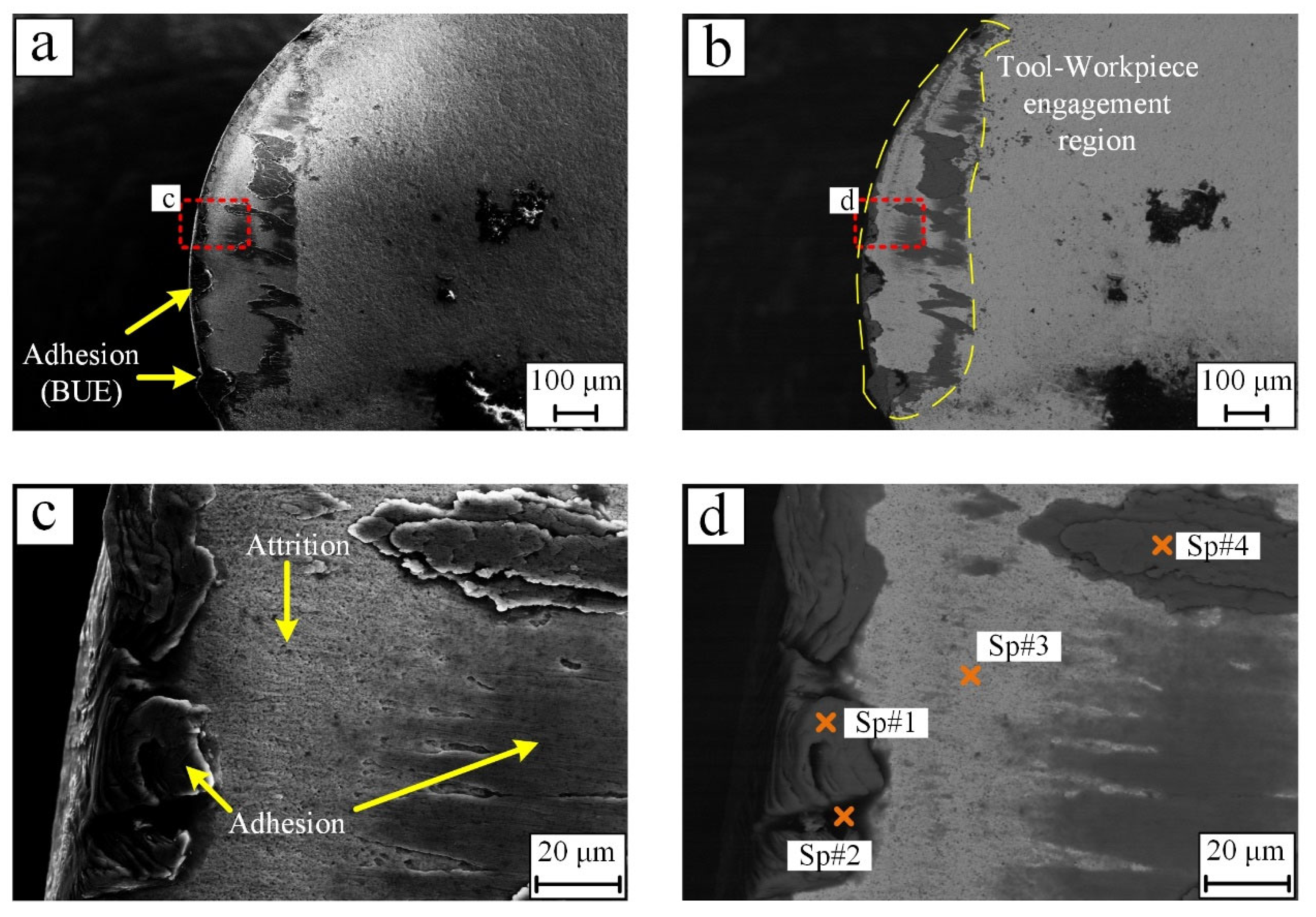
The detailed morphology of the worn areas on cutting inserts was observed via SEM as presented in Figure 16, Figure 17, Figure 18 and Figure 19, and the residual elements in the worn areas were analyzed via EDS, as listed in Table 5, Table 6, Table 7 and Table 8. It can be seen that adhesion-abrasion wear was the dominant mechanism for the inserts in all cutting processes. The darker regions represent areas where adhesion of Ti6Al4V from the workpiece occurred, and the lighter regions represent exposed tool surface, consisting primarily of WC and Co. Generally, the worn areas can be divided into three regions: sticking zone, transition zone and sliding zone, according to the distribution of chip load and chip flow speed on the tool surface [31]. In the sticking zone, the build-up edge (BUE) caused by the adhesion of the workpiece is evident. Compared with the inserts used for machining SLMed tubes, the formation of BUE was more significant when machining wrought material. Especially, a large-area build-up layer (BUL) was formed when machining wrought material at the cutting depth of 0.25 mm, which could be ascribed to the combination of the lower hardness and thermal softening effects in the machining of wrought material. In the transition zone, chip flow starts to accelerate attrition wear, which becomes dominant in this region. As shown in the Figure 16c, Figure 17c, Figure 18c and Figure 19c, the exposed tool surface near the sticking region was observed, and the sticking region was larger at the cutting depth of 0.5 mm. In the sliding zone, the velocity of the chip flow increased to its highest, whereas the tool/chip stress decreased to its lowest, leading to the adhesion of the softened chip on the tool surface. The sliding regions on the insert machining wrought material were larger and irregular, due to the thermal softening of the workpiece material. According to the EDS results, the appearance of C and O elements indicates oxidation-induced chemical wear in combination with diffusion of carbon from the tool insert during the cutting process [32]. In Figure 16d, Figure 17d, Figure 18d and Figure 19d, the oxygen-rich and carbon-rich spots are located either in areas of Ti alloy adhesion or in the dark regions where the chip–tool contact is severed. In the dry cutting of Ti6Al4V, the cutting temperature can reach over 800 °C at the tool/chip interface, causing the oxidation of the tool surface or diffusion of carbon from the adhered Ti alloy [33].
4. Conclusions
In this study, the machinability of SLM-fabricated Ti6Al4V tubes was investigated in terms of cutting forces, surface roughness and tool wear. The results were compared with wrought counterparts. The main findings are:
- (i)
- The cutting depth is the most influential cutting parameter. Both the main cutting forces (Fc) and radial forces (Fr) when machining SLMed Ti workpieces were lesser (55–70%) than while machining wrought parts at a smaller cutting depth of 0.25 mm. However, an inverse trend was observed at a greater cutting depth of 0.5 mm, where the resultant cutting force when machining the SLMed Ti workpiece was higher by about 10% when machining wrought counterparts.
- (ii)
- The main and radial cutting forces were greater while machining wrought workpieces under all cutting conditions compared to SLMed Ti tubes.
- (iii)
- Vibrational analysis conducted on the cutting forces showed that the main frequency of the main cutting forces was about 1.5 Hz, irrespective of the workpiece condition. However, some high frequency peaks were also found distributed within the range of 200 Hz to 1200 Hz.
- (iv)
- The machined surface roughness of both the wrought and SLMed Ti workpieces were similar, with the roughness below 2 μm, indicating that the roughness in finish machining was not affected by variations in cutting forces and tool wear.
- (v)
- The results obtained from the tool wear analysis shows that there was larger tool–workpiece engagement area on the tools used to machine the wrought parts as compared with that on tools used to machine SLMed parts.
- (vi)
- Both adhesion and attrition wear were found to be the dominant tool wear mechanisms, irrespective of the cutting conditions or the workpiece state.
Author Contributions
Conceptualization, R.A.R.R., S.S. and S.P.; methodology, G.L. and R.A.R.R.; software, G.L.; validation, G.L. and R.A.R.R.; formal analysis, G.L.; investigation, G.L. and R.A.R.R.; resources, S.P. and S.D.; data curation, G.L. and R.A.R.R.; writing—original draft preparation, G.L. and R.A.R.R.; writing—review and editing, S.D., S.S. and S.P.; supervision, S.D. and S.P.; project administration, S.D. and S.P.; funding acquisition, S.P. All authors have read and agreed to the published version of the manuscript.
Funding
This research was funded by DMTC Ltd., project number 5.84.
Institutional Review Board Statement
Not Applicable.
Informed Consent Statement
Not Applicable.
Data Availability Statement
All processed data have been presented in this publication. The raw data that support the findings of this study are available from the corresponding author S.P. upon reasonable request.
Acknowledgments
This research project was supported by the DMTC Limited (Australia). The paper has been written in line with the intellectual property rights granted to research partners from the original DMTC project.
Conflicts of Interest
The authors declare no conflict of interest.
Nomenclature
| AM | Additive manufacturing |
| PBF | Powder bed fusion |
| EBM | Electron beam melting |
| SLM | Selective laser melting |
| DMLS | Direct metal laser sintering |
| MQL | Minimum quantity lubrication |
| FFT | Fast Fourier Transformation |
| BUE | Build-up edge |
| BUL | Build-up layer |
References
- Li, G.; Chandra, S.; Rashid, R.; Palanisamy, S.; Ding, S. Machinability of additively manufactured titanium alloys: A comprehensive review. J. Manuf. Processes 2022, 75, 72–99. [Google Scholar] [CrossRef]
- Li, G.; Yi, S.; Li, N.; Pan, W.; Wen, C.; Ding, S. Quantitative analysis of cooling and lubricating effects of graphene oxide nanofluids in machining titanium alloy Ti6Al4V. J. Mater. Process. Technol. 2019, 271, 584–598. [Google Scholar] [CrossRef]
- Mower, T.; Long, M. Mechanical behavior of additive manufactured, powder-bed laser-fused materials. Mater. Sci. Eng. A 2016, 651, 198–213. [Google Scholar] [CrossRef]
- Attar, H.; Ehetemam, S.; Kent, D.; Dargusch, M. Recent developments and opportunities in additive manufacturing of titanium-based matrix composites: A review. Int. J. Mach. Tools Manuf. 2018, 133, 85–102. [Google Scholar] [CrossRef]
- Cottam, R.; Palanisamy, S.; Avdeev, M.; Jarvis, T.; Henry, C.; Cuiuri, D.; Balogh, L.; Rashid, R. Diffraction line profile analysis of 3D wedge samples of Ti-6Al-4V fabricated using four different additive manufacturing processes. Metals 2019, 9, 60. [Google Scholar] [CrossRef] [Green Version]
- Ngo, T.D.; Kashani, A.; Imbalzano, G.; Nguyen, K.T.D.; Hui, D. Additive manufacturing (3D printing): A review of materials, methods, applications and challenges. Compos. Part B Eng. 2018, 143, 172–196. [Google Scholar] [CrossRef]
- Hoye, N.; Cuiuri, D.; Rashid, R.; Palanisamy, S. Machining of GTAW additively manufactured Ti-6Al-4V structures. Int. J. Adv. Manuf. Technol. 2018, 99, 313–326. [Google Scholar] [CrossRef]
- Khanna, N.; Zadafiya, K.; Patel, T.; Kaynak, Y.; Rashid, R.; Vafadar, A. Review on machining of additively manufactured nickel and titanium alloys. J. Mater. Res. Technol. 2021, 15, 3192–3221. [Google Scholar] [CrossRef]
- Yan, M.; Yu, P. An Overview of densification, microstructure and mechanical property of additively manufactured Ti-6Al-4V—Comparison among selective laser melting, electron beam melting, laser metal deposition and selective laser sintering, and with conventional powder. Sinter. Tech. Mater. 2015. [Google Scholar] [CrossRef]
- Murr, L.E.; Esquivel, E.V.; Quinones, S.A.; Gaytan, S.M.; Lopez, M.I.; Martinez, E.Y.; Medina, F.; Hernandez, D.H.; Martinez, E.; Martinez, J.L.; et al. Microstructures and mechanical properties of electron beam-rapid manufactured Ti–6Al–4V biomedical prototypes compared to wrought Ti–6Al–4V. Mater. Charact. 2009, 60, 96–105. [Google Scholar] [CrossRef]
- Le Coz, G.; Fischer, M.; Piquard, R.; D’Acunto, A.; Laheurte, P.; Dudzinski, D. Micro cutting of Ti-6Al-4V parts produced by SLM process. Procedia Cirp 2017, 58, 228–232. [Google Scholar] [CrossRef]
- Shunmugavel, M.; Polishetty, A.; Goldberg, M.; Singh, R.; Littlefair, G. A comparative study of mechanical properties and machinability of wrought and additive manufactured (selective laser melting) titanium alloy–Ti-6Al-4V. Rapid Prototyp. J. 2017, 23, 1051–1056. [Google Scholar] [CrossRef]
- Kallel, A.; Duchosal, A.; Altmeyer, G.; Morandeau, A.; Hamdi, H.; Leroy, R.; Méo, S. Finish milling study of Ti-6Al-4V produced by Laser Metal Deposition (LMD). MM Sci. J. 2019, 2019, 3067–3070. [Google Scholar] [CrossRef] [Green Version]
- Hojati, F.; Daneshi, A.; Soltani, B.; Azarhoushang, B.; Biermann, D. Study on machinability of additively manufactured and conventional titanium alloys in micro-milling process. Precis. Eng. 2020, 62, 1–9. [Google Scholar] [CrossRef]
- Bruschi, S.; Bertolini, R.; Bordin, A.; Medea, F.; Ghiotti, A. Influence of the machining parameters and cooling strategies on the wear behavior of wrought and additive manufactured Ti6Al4V for biomedical applications. Tribol. Int. 2016, 102, 133–142. [Google Scholar] [CrossRef]
- Li, G.; Yi, S.; Wen, C.; Ding, S. Wear mechanism and modeling of tribological behavior of polycrystalline diamond tools when cutting Ti6Al4V. J. Manuf. Sci. Eng. 2018, 140, 121011–121026. [Google Scholar] [CrossRef]
- Al-Rubaie, K.S.; Melotti, S.; Rabelo, A.; Paiva, J.M.; Elbestawi, M.A.; Veldhuis, S.C. Machinability of SLM-produced Ti6Al4V titanium alloy parts. J. Manuf. Processes 2020, 57, 768–786. [Google Scholar] [CrossRef]
- Pérez-Ruiz, J.D.; López de Lacalle, L.N.; Urbikain, G.; Pereira, O.; Martínez, S.; Bris, J. On the relationship between cutting forces and anisotropy features in the milling of LPBF Inconel 718 for near net shape parts. Int. J. Mach. Tools Manuf. 2021, 170, 103801. [Google Scholar] [CrossRef]
- Pérez-Ruiz, J.D.; Marin, F.; Martínez, S.; Lamikiz, A.; Urbikain, G.; López de Lacalle, L.N. Stiffening near-net-shape functional parts of Inconel 718 LPBF considering material anisotropy and subsequent machining issues. Mech. Syst. Signal Process. 2022, 168, 108675. [Google Scholar] [CrossRef]
- Lizzul, L.; Sorgato, M.; Bertolini, R.; Ghiotti, A.; Bruschi, S. Influence of additive manufacturing-induced anisotropy on tool wear in end milling of Ti6Al4V. Tribol. Int. 2020, 146, 106200. [Google Scholar] [CrossRef]
- Rodríguez, A.; Calleja, A.; López de Lacalle, L.N.; Pereira, O.; Rubio-Mateos, A.; Rodríguez, G. Drilling of CFRP-Ti6Al4V stacks using CO2-cryogenic cooling. J. Manuf. Processes 2021, 64, 58–66. [Google Scholar] [CrossRef]
- Gonzalez, H.; Pereira, O.; López de Lacalle, L.N.; Calleja, A.; Ayesta, I.; Muñoa, J. Flank-milling of integral blade rotors made in Ti6Al4V using Cryo CO2 and minimum quantity lubrication. J. Manuf. Sci. Eng. 2021, 143, 1–16. [Google Scholar] [CrossRef]
- Amigo, F.J.; Urbikain, G.; Pereira, O.; Fernández-Lucio, P.; Fernández-Valdivielso, A.; López de Lacalle, L.N. Combination of high feed turning with cryogenic cooling on Haynes 263 and Inconel 718 superalloys. J. Manuf. Processes 2020, 58, 208–222. [Google Scholar] [CrossRef]
- Bordin, A.; Imbrogno, S.; Rotella, G.; Bruschi, S.; Ghiotti, A.; Umbrello, D. Finite element simulation of semi-finishing turning of electron beam melted Ti6Al4V under dry and cryogenic cooling. Procedia CIRP 2015, 31, 551–556. [Google Scholar] [CrossRef]
- Sartori, S.; Moro, L.; Ghiotti, A.; Bruschi, S. On the tool wear mechanisms in dry and cryogenic turning Additive Manufactured titanium alloys. Tribol. Int. 2017, 105, 264–273. [Google Scholar] [CrossRef]
- Pimenov, D.Y.; Mia, M.; Gupta, M.K.; Machado, A.R.; Tomaz, Í.V.; Sarikaya, M.; Wojciechowski, S.; Mikolajczyk, T.; Kapłonek, W. Improvement of machinability of Ti and its alloys using cooling-lubrication techniques: A review and future prospect. J. Mater. Res. Technol. 2021, 11, 719–753. [Google Scholar] [CrossRef]
- Khaliq, W.; Zhang, C.; Jamil, M.; Khan, A.M. Tool wear, surface quality, and residual stresses analysis of micro-machined additive manufactured Ti–6Al–4V under dry and MQL conditions. Tribol. Int. 2020, 151, 106408. [Google Scholar] [CrossRef]
- Cao, H.; Zhou, K.; Chen, X. Stability-based selection of cutting parameters to increase material removal rate in high-speed machining process. Proc. Inst. Mech. Eng. Part B J. Eng. Manuf. 2016, 230, 227–240. [Google Scholar] [CrossRef]
- Kallel, A.; Duchosal, A.; Hamdi, H.; Altmeyer, G.; Morandeau, A.; Méo, S. Analysis of the surface integrity induced by face milling of Laser Metal Deposited Ti-6Al-4V. Procedia CIRP 2020, 87, 345–350. [Google Scholar] [CrossRef]
- Rotella, G.; Imbrogno, S.; Candamano, S.; Umbrello, D. Surface integrity of machined additively manufactured Ti alloys. J. Mater. Process. Technol. 2018, 259, 180–185. [Google Scholar] [CrossRef]
- Bahi, S.; Nouari, M.; Moufki, A.; EI Mansori, M.; Molinari, A. Hybrid modelling of sliding–sticking zones at the tool–chip interface under dry machining and tool wear analysis. Wear 2012, 286–287, 45–54. [Google Scholar] [CrossRef]
- Rashid, R.; Palanisamy, S.; Sun, S.; Dargusch, M. Tool wear mechanisms involved in crater formation on uncoated carbide tool when machining Ti6Al4V alloy. Int. J. Adv. Manuf. Technol. 2016, 83, 1457–1465. [Google Scholar] [CrossRef]
- Dargusch, M.; Sivarupan, T.; Bermingham, M.; Rashid, R.; Palanisamy, S.; Sun, S. Challenges in laser-assisted milling of titanium alloys. Int. J. Extrem. Manuf. 2021, 3, 015001. [Google Scholar] [CrossRef]
Figure 1.
The wrought and additive-manufactured Ti6Al4V tubes.

Figure 2.
Experimental setup of the turning experiment: (a) machine tool, workpiece, and tool assembly, and (b) force measurement system.
Figure 2.
Experimental setup of the turning experiment: (a) machine tool, workpiece, and tool assembly, and (b) force measurement system.
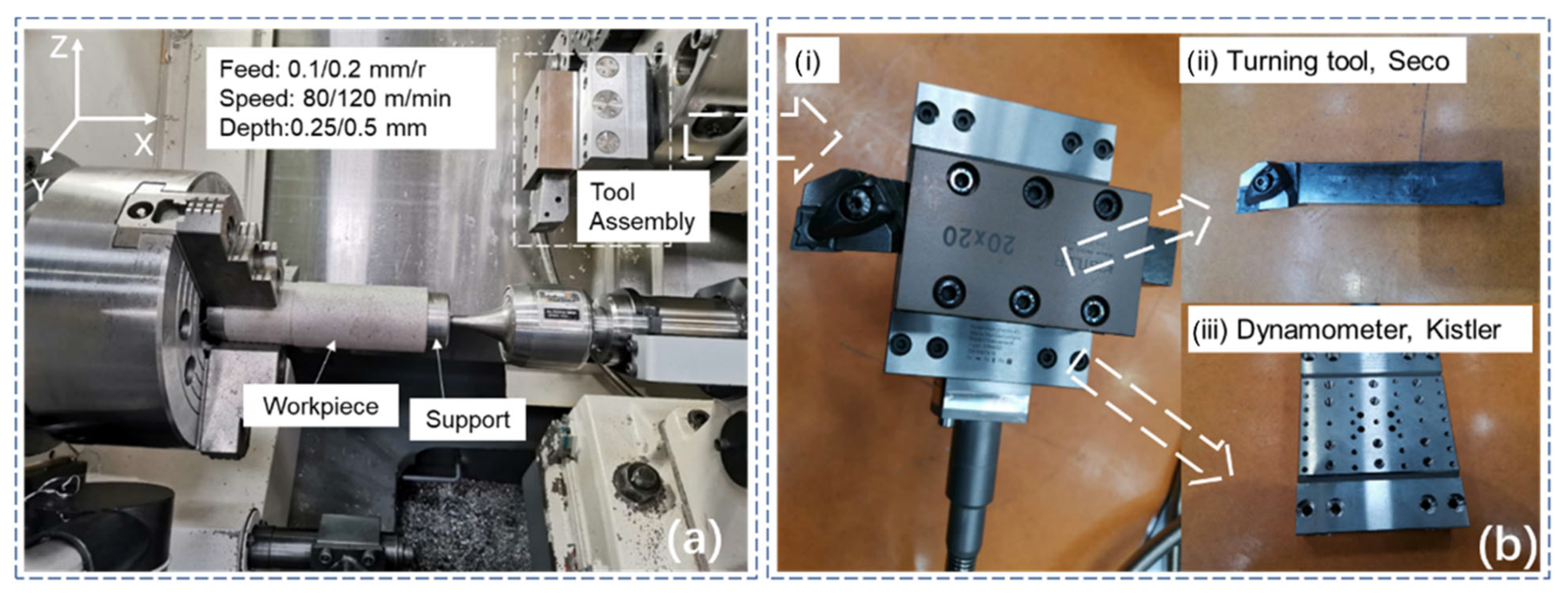
Figure 3.
Cutting forces when machining wrought and SLMed Ti6Al4V workpieces at the cutting parameters of 0.1 mm/rev and 80 m/min.
Figure 3.
Cutting forces when machining wrought and SLMed Ti6Al4V workpieces at the cutting parameters of 0.1 mm/rev and 80 m/min.

Figure 4.
Cutting forces when machining wrought and SLMed Ti6Al4V workpieces at the cutting parameters of 0.2 mm/rev and 80 m/min.
Figure 4.
Cutting forces when machining wrought and SLMed Ti6Al4V workpieces at the cutting parameters of 0.2 mm/rev and 80 m/min.

Figure 5.
Cutting forces when machining wrought and SLMed Ti6Al4V workpieces at the cutting parameters of 0.2 mm/rev and 120 m/min.
Figure 5.
Cutting forces when machining wrought and SLMed Ti6Al4V workpieces at the cutting parameters of 0.2 mm/rev and 120 m/min.
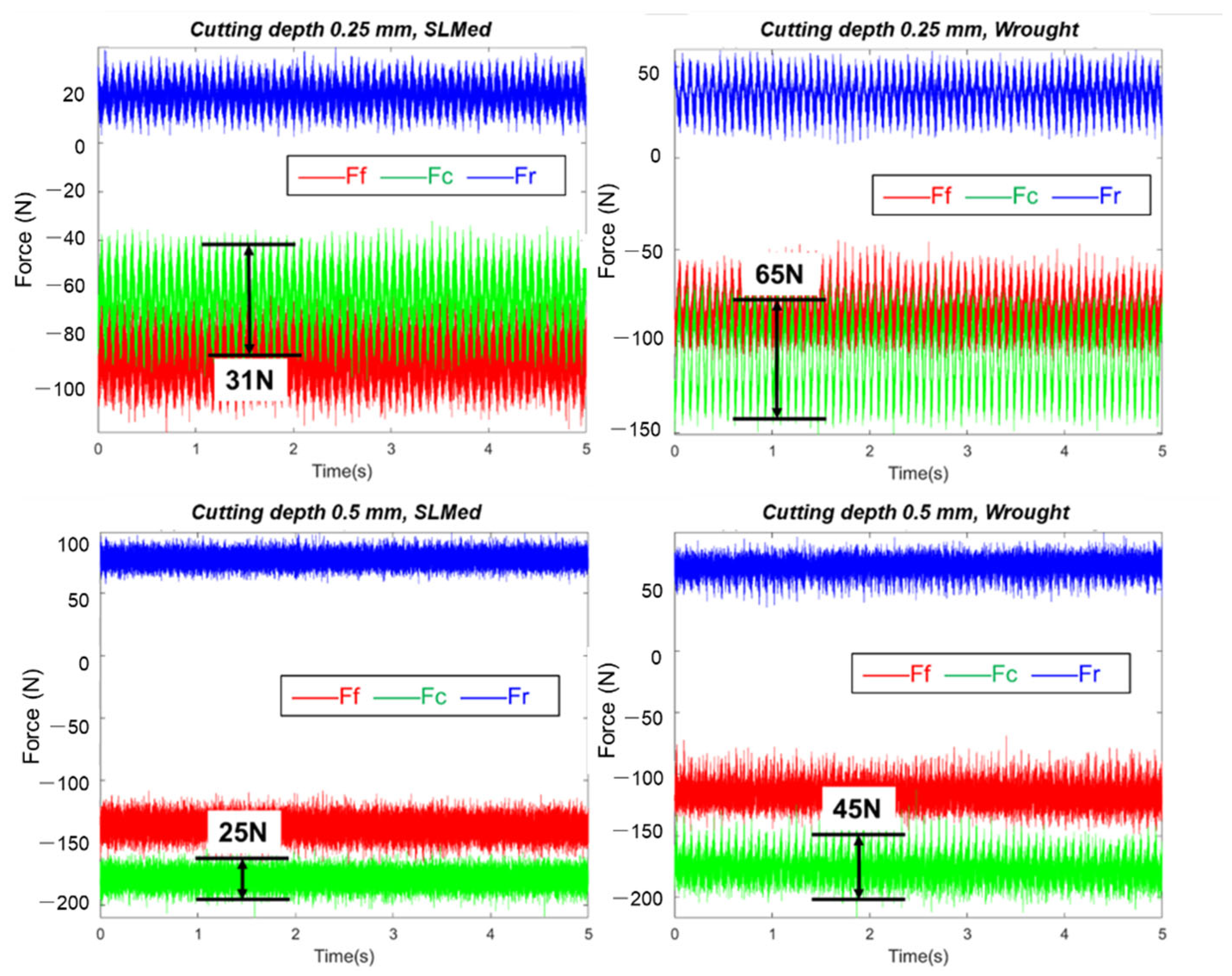
Figure 6.
Cutting forces when machining wrought and SLMed Ti6Al4V workpieces at the cutting parameters of 0.1 mm/rev and 120 m/min.
Figure 6.
Cutting forces when machining wrought and SLMed Ti6Al4V workpieces at the cutting parameters of 0.1 mm/rev and 120 m/min.
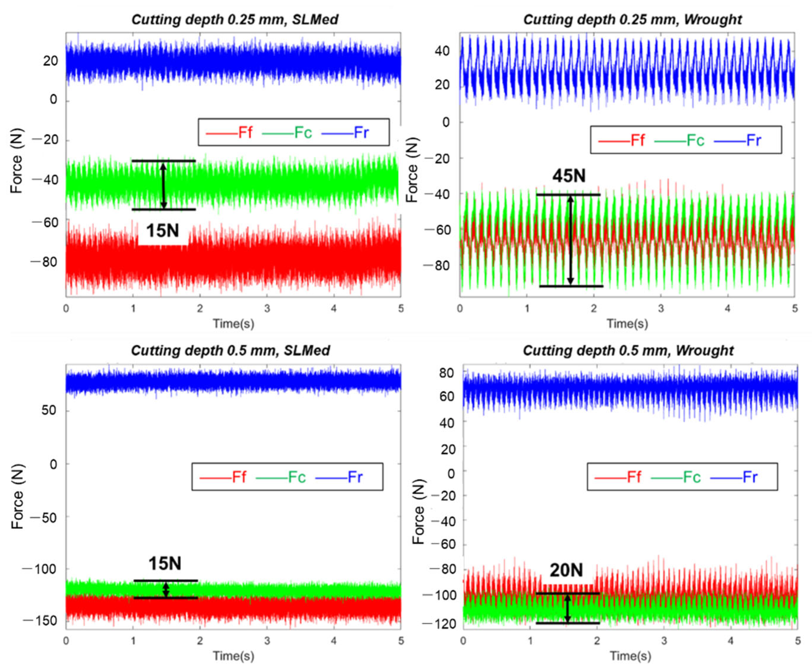
Figure 7.
Average values of the three-axis cutting forces at different cutting parameters: (a) cutting depth 0.25 mm, cutting speed 80 m/min, (b) cutting depth 0.25 mm, cutting speed 120 m/min, (c) cutting depth 0.5 mm, cutting speed 80 m/min, (d) cutting depth 0.5 mm, cutting speed 120 m/min.
Figure 7.
Average values of the three-axis cutting forces at different cutting parameters: (a) cutting depth 0.25 mm, cutting speed 80 m/min, (b) cutting depth 0.25 mm, cutting speed 120 m/min, (c) cutting depth 0.5 mm, cutting speed 80 m/min, (d) cutting depth 0.5 mm, cutting speed 120 m/min.
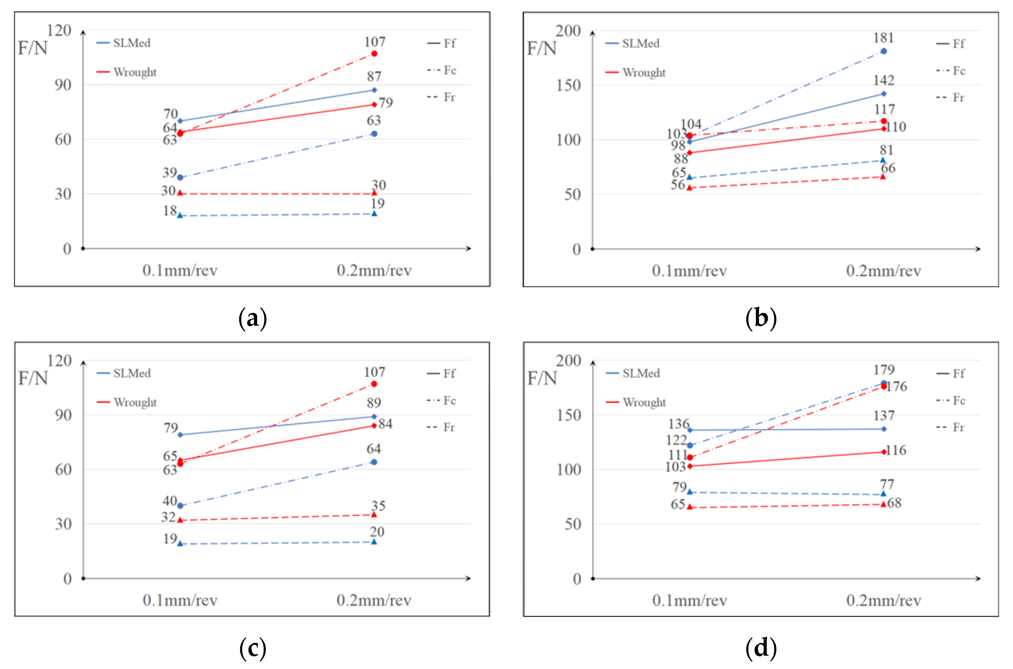
Figure 8.
FFT of the signal of radial force when machining wrought and SLMed Ti6Al4V materials at the speed of 80 m/min and feed of 0.1 mm/rev: (a) at the cutting depth of 0.25 mm, (b) at the cutting depth of 0.5 mm.
Figure 8.
FFT of the signal of radial force when machining wrought and SLMed Ti6Al4V materials at the speed of 80 m/min and feed of 0.1 mm/rev: (a) at the cutting depth of 0.25 mm, (b) at the cutting depth of 0.5 mm.

Figure 9.
FFT of the signal of radial force when machining wrought and SLMed Ti6Al4V materials at the speed of 80 m/min and feed of 0.2 mm/rev: (a) at the cutting depth of 0.25 mm, (b) at the cutting depth of 0.5 mm.
Figure 9.
FFT of the signal of radial force when machining wrought and SLMed Ti6Al4V materials at the speed of 80 m/min and feed of 0.2 mm/rev: (a) at the cutting depth of 0.25 mm, (b) at the cutting depth of 0.5 mm.

Figure 10.
FFT of the signal of radial force when machining wrought and SLMed Ti6Al4V materials at the speed of 120 m/min and feed of 0.2 mm/rev: (a) at the cutting depth of 0.25 mm, (b) at the cutting depth of 0.5 mm.
Figure 10.
FFT of the signal of radial force when machining wrought and SLMed Ti6Al4V materials at the speed of 120 m/min and feed of 0.2 mm/rev: (a) at the cutting depth of 0.25 mm, (b) at the cutting depth of 0.5 mm.
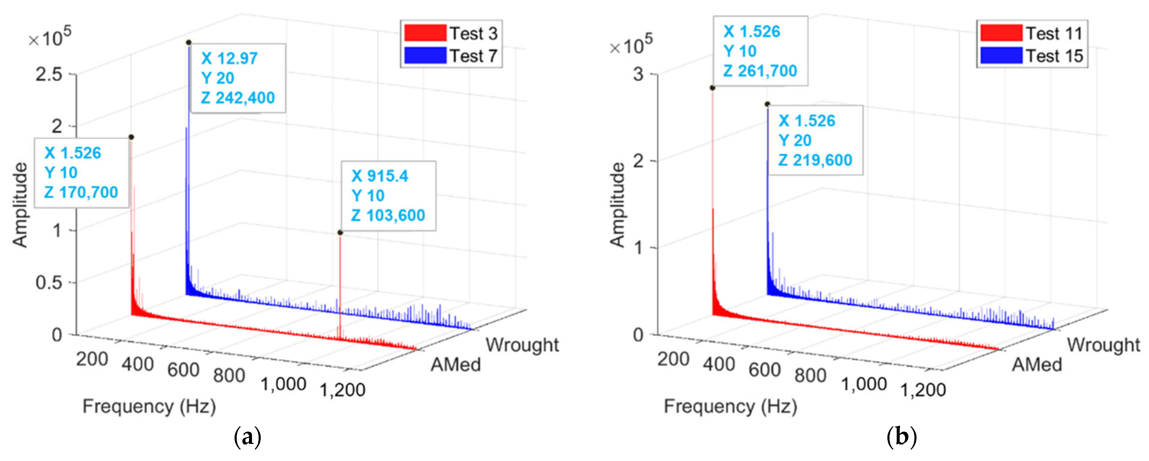
Figure 11.
FFT of the signal of radial force when machining wrought and SLMed Ti6Al4V materials at the speed of 120 m/min and feed of 0.1 mm/rev: (a) at the cutting depth of 0.25 mm, (b) at the cutting depth of 0.5 mm.
Figure 11.
FFT of the signal of radial force when machining wrought and SLMed Ti6Al4V materials at the speed of 120 m/min and feed of 0.1 mm/rev: (a) at the cutting depth of 0.25 mm, (b) at the cutting depth of 0.5 mm.
Figure 12.
Profile of the machined surface of SLMed Ti6Al4V at the cutting depth of 0.25 mm, (a) feed rate: 0.1 mm/rev, speed: 80 m/min; (b) feed rate: 0.2 mm/rev, speed: 80 m/min; (c) feed rate: 0.2 mm/rev, speed: 120 m/min; (d) feed rate: 0.1 mm/rev, speed: 120 m/min.
Figure 12.
Profile of the machined surface of SLMed Ti6Al4V at the cutting depth of 0.25 mm, (a) feed rate: 0.1 mm/rev, speed: 80 m/min; (b) feed rate: 0.2 mm/rev, speed: 80 m/min; (c) feed rate: 0.2 mm/rev, speed: 120 m/min; (d) feed rate: 0.1 mm/rev, speed: 120 m/min.

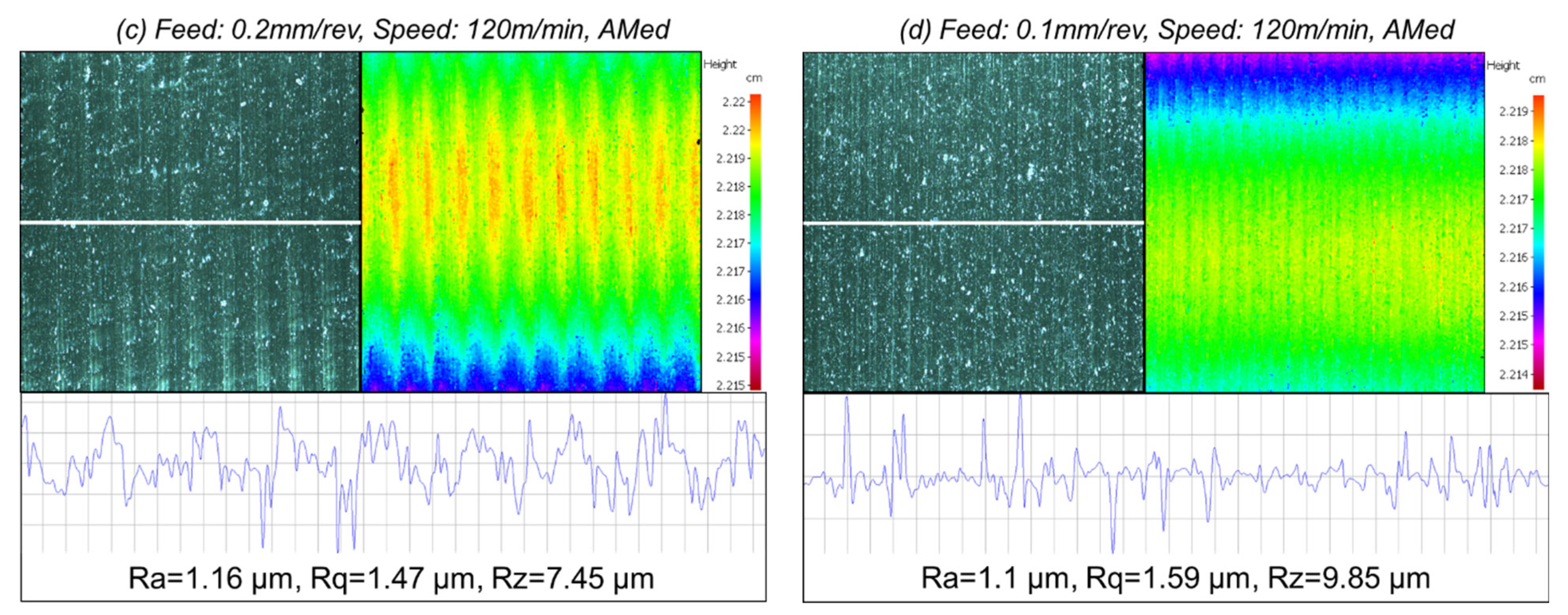
Figure 13.
Profile of the machined surface of wrought Ti6Al4V at the cutting depth of 0.25 mm, (a) feed rate: 0.1 mm/rev, speed: 80 m/min; (b) feed rate: 0.2 mm/rev, speed: 80 m/min; (c) feed rate: 0.2 mm/rev, speed: 120 m/min; (d) feed rate: 0.1 mm/rev, speed: 120 m/min.
Figure 13.
Profile of the machined surface of wrought Ti6Al4V at the cutting depth of 0.25 mm, (a) feed rate: 0.1 mm/rev, speed: 80 m/min; (b) feed rate: 0.2 mm/rev, speed: 80 m/min; (c) feed rate: 0.2 mm/rev, speed: 120 m/min; (d) feed rate: 0.1 mm/rev, speed: 120 m/min.
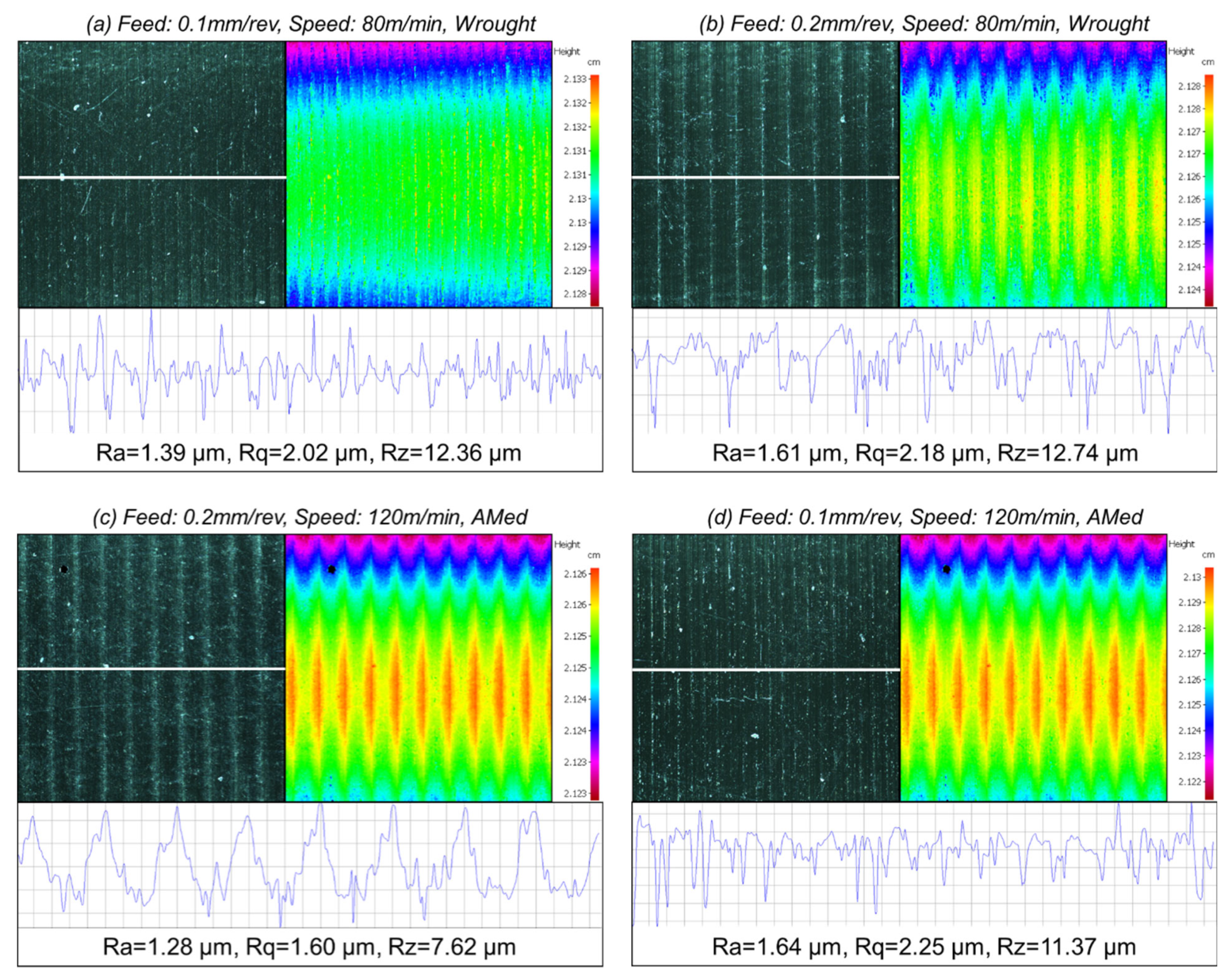
Figure 14.
Profile of the machined surface of SLMed Ti6Al4V at the cutting depth of 0.5 mm, (a) feed rate: 0.1 mm/rev, speed: 80 m/min; (b) feed rate: 0.2 mm/rev, speed: 80 m/min; (c) feed rate: 0.2 mm/rev, speed: 120 m/min; (d) feed rate: 0.1 mm/rev, speed: 120 m/min.
Figure 14.
Profile of the machined surface of SLMed Ti6Al4V at the cutting depth of 0.5 mm, (a) feed rate: 0.1 mm/rev, speed: 80 m/min; (b) feed rate: 0.2 mm/rev, speed: 80 m/min; (c) feed rate: 0.2 mm/rev, speed: 120 m/min; (d) feed rate: 0.1 mm/rev, speed: 120 m/min.
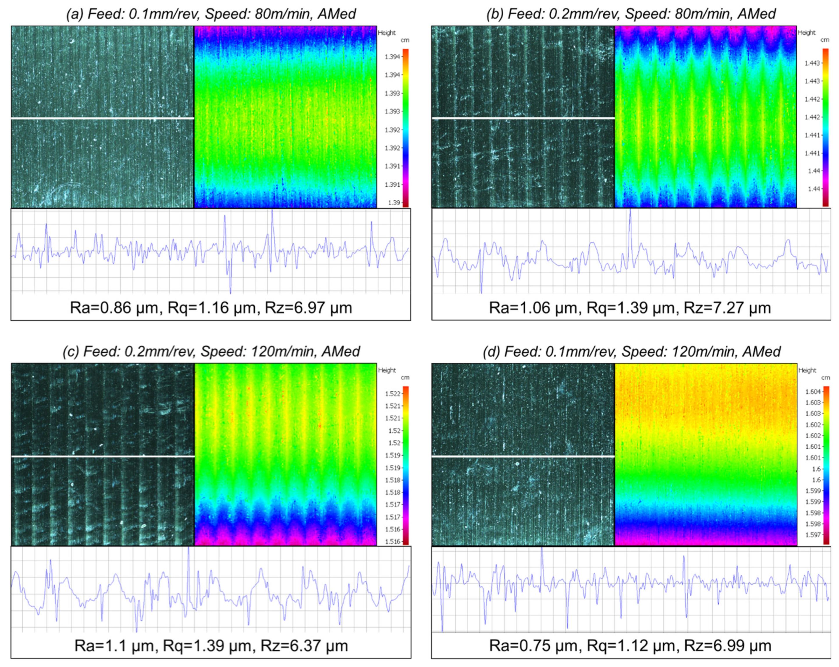
Figure 15.
Profile of the machined surface of wrought Ti6Al4V at the cutting depth of 0.5 mm, (a) feed rate: 0.1 mm/rev, speed: 80 m/min; (b) feed rate: 0.2 mm/rev, speed: 80 m/min; (c) feed rate: 0.2 mm/rev, speed: 120 m/min; (d) feed rate: 0.1 mm/rev, speed: 120 m/min.
Figure 15.
Profile of the machined surface of wrought Ti6Al4V at the cutting depth of 0.5 mm, (a) feed rate: 0.1 mm/rev, speed: 80 m/min; (b) feed rate: 0.2 mm/rev, speed: 80 m/min; (c) feed rate: 0.2 mm/rev, speed: 120 m/min; (d) feed rate: 0.1 mm/rev, speed: 120 m/min.
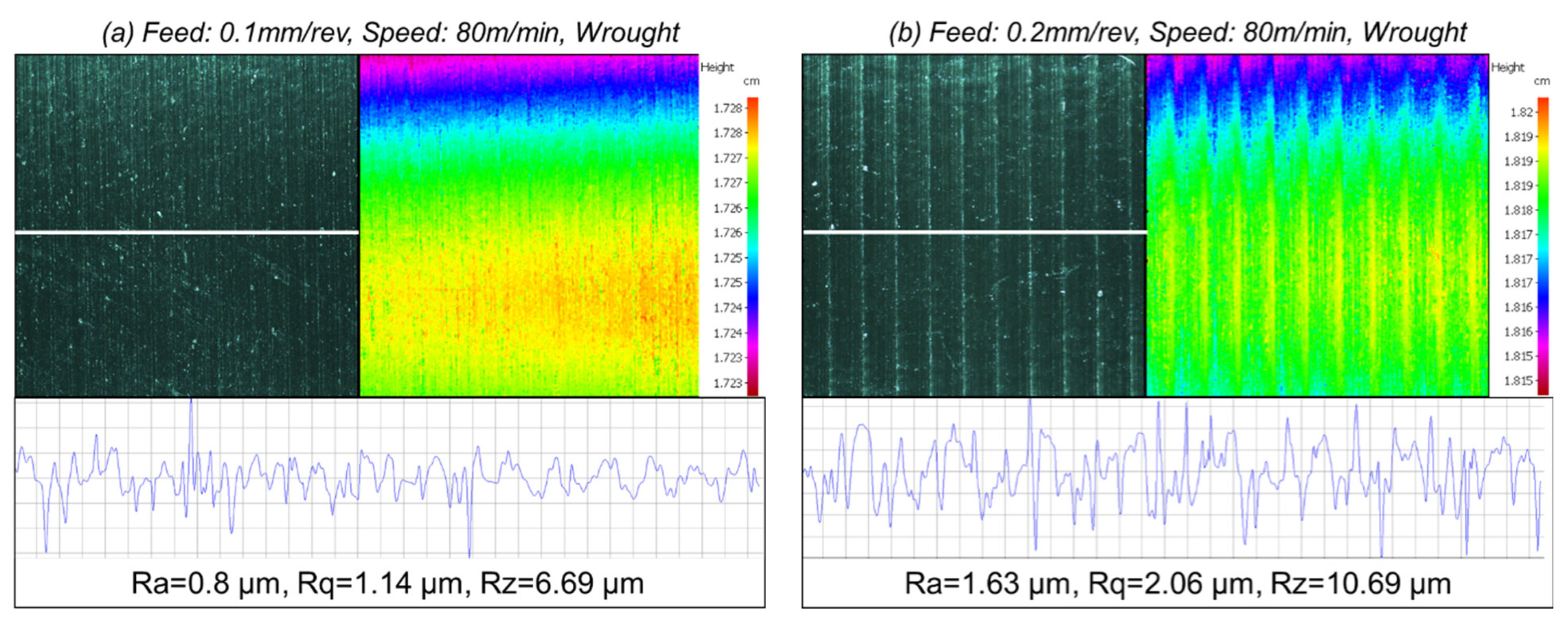

Figure 16.
The worn inserts after machining SLMed titanium tubes at a cutting depth of 0.25 mm: (a) secondary electron image showing the overview of the worn area, (b) backscatter electron image highlighting tool-workpiece contact area, (c) enlarged area of shown in (a), and (d) enlarged area shown in (b).
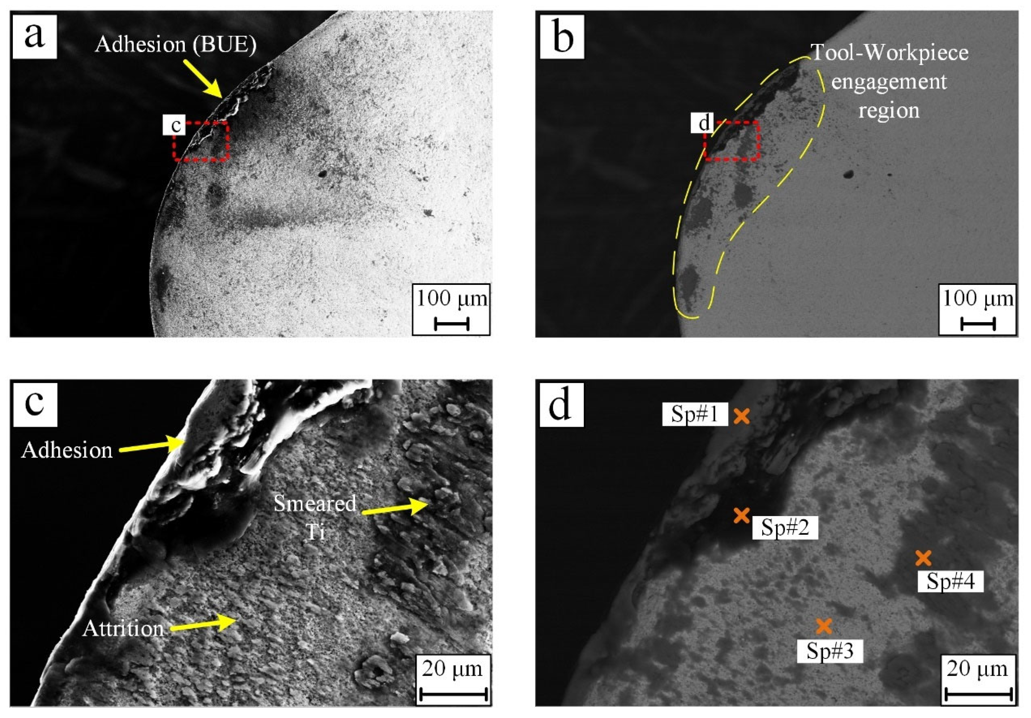
Figure 17.
The worn inserts after machining wrought titanium tubes at a cutting depth of 0.25 mm: (a) secondary electron image showing the overview of the worn area, (b) backscatter electron image highlighting tool-workpiece contact area, (c) enlarged area of shown in (a), and (d) enlarged area shown in (b).
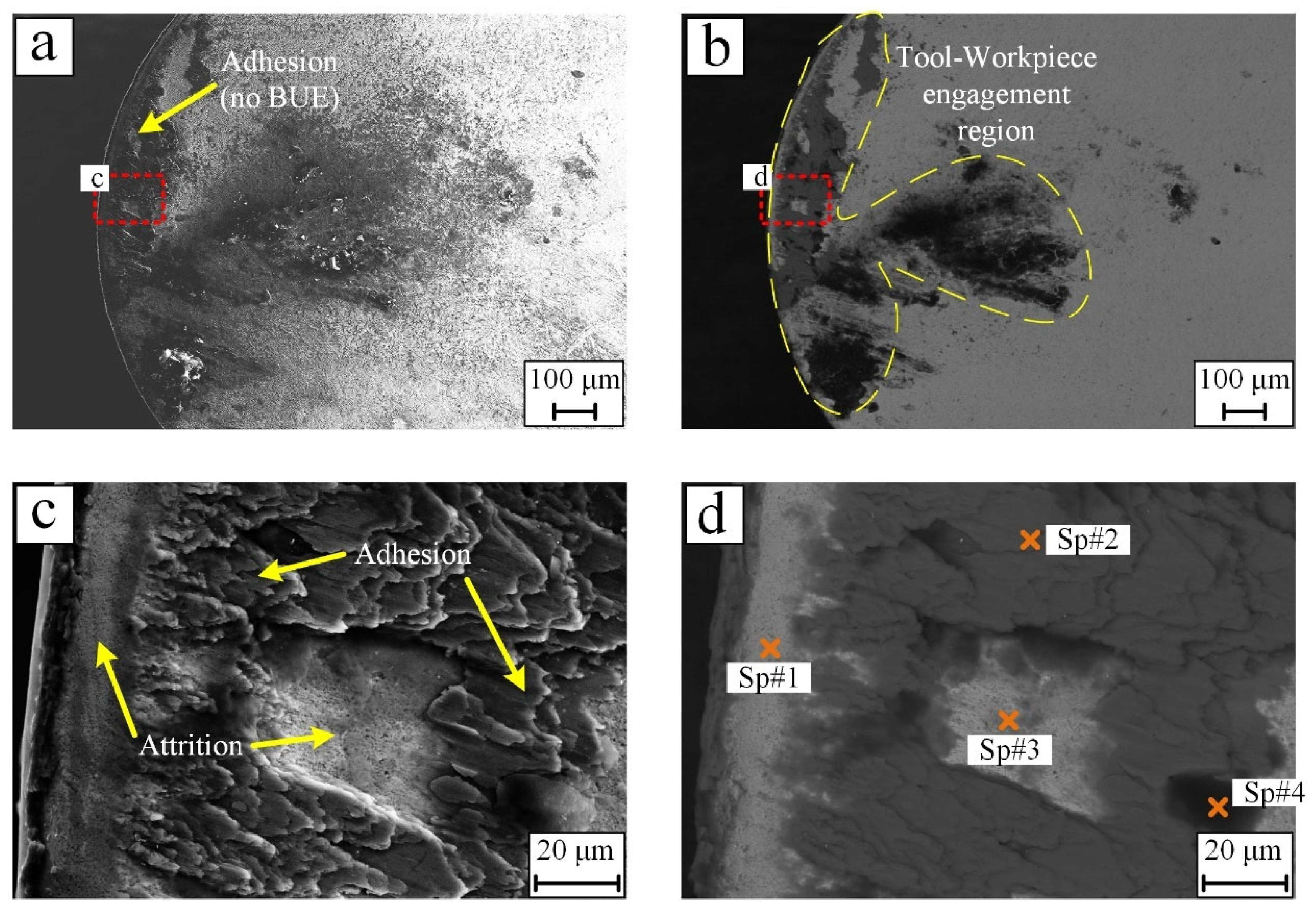
Figure 18.
The worn inserts after machining SLMed titanium tubes at a cutting depth of 0.5 mm: (a) secondary electron image showing the overview of the worn area, (b) backscatter electron image highlighting tool-workpiece contact area, (c) enlarged area of shown in (a), and (d) enlarged area shown in (b).

Figure 19.
The worn inserts after machining wrought titanium tubes at a cutting depth of 0.5 mm: (a) secondary electron image showing the overview of the worn area, (b) backscatter electron image highlighting tool-workpiece contact area, (c) enlarged area of shown in (a), and (d) enlarged area shown in (b).

Table 1.
Mechanical properties of titanium alloy Ti6Al4V fabricated by different methods, data from [3,9,10,11].
| Fabrication Method | Hardness (HRC) | Yield Strength (MPa) | Tensile Strength (MPa) | Elastic Modulus (GPa) |
|---|---|---|---|---|
| Wrought | 31 | 790 | 872 | 118 |
| EBM | 35 | 830 | 914 | 114 |
| SLM | 41 | 1125 | 1250 | 94 |
| DMLS | 44 | 990 | 1095 | 110 |
Table 2.
Geometry of the cutting insert used in this study.
| Insert View | Clearance Angle | Included Angle | Cutting Edge Length | Corner Radius |
|---|---|---|---|---|
 | 0° | 80° | 12.9 mm | 0.8 mm |
Table 3.
Cutting parameters of the turning experiment.
| Test No. | Feed Rate (mm/rev) | Cutting Speed (m/min) | Cutting Depth (mm) | Workpiece |
|---|---|---|---|---|
| 1 | 0.1 | 80 | 0.25 | SLMed |
| 2 | 0.2 | |||
| 3 | 120 | |||
| 4 | 0.1 | |||
| 5 | 80 | Wrought | ||
| 6 | 0.2 | |||
| 7 | 120 | |||
| 8 | 0.1 | |||
| 9 | 80 | 0.5 | SLMed | |
| 10 | 0.2 | |||
| 11 | 120 | |||
| 12 | 0.1 | |||
| 13 | 80 | Wrought | ||
| 14 | 0.2 | |||
| 15 | 120 | |||
| 16 | 0.1 |
Table 4.
The cutting forces when machining wrought and SLMed Ti6Al4V at different cutting parameters.
Table 4.
The cutting forces when machining wrought and SLMed Ti6Al4V at different cutting parameters.
| Cutting Depth | Workpiece | Cutting Forces | 80 m/min 0.1 mm/rev | 80 m/min 0.2 mm/rev | 120 m/min 0.1 mm/rev | 120 m/min 0.2 mm/rev |
|---|---|---|---|---|---|---|
| 0.25 mm | SLMed | Fres | 82 N | 82 N | 90 N | 111 N |
| Wrought | Fres | 95 N | 135 N | 96 N | 140 N | |
| 0.5 mm | SLMed | Fres | 156 N | 244 N | 199 N | 238 N |
| Wrought | Fres | 147 N | 219 N | 165 N | 222 N |
Table 5.
EDS Spectral analysis of locations identified in Figure 16d.
Table 5.
EDS Spectral analysis of locations identified in Figure 16d.
| Tool Elements | Workpiece Elements | Other | |||||
|---|---|---|---|---|---|---|---|
| W | C | Co | Ti | Al | V | O | |
| Sp#1 | 0.45 | 23.62 | 0.13 | 61.22 | 3.80 | 1.69 | 8.81 |
| Sp#2 | 3.35 | 73.47 | 0.38 | 12.17 | 1.03 | 0.88 | 8.09 |
| Sp#3 | 58.77 | 28.50 | 2.23 | 6.09 | 0.44 | 0.21 | 2.67 |
| Sp#4 | 12.94 | 22.88 | 0.29 | 54.78 | 2.95 | 1.76 | 4.27 |
Table 6.
EDS Spectral analysis of locations identified in Figure 17d.
Table 6.
EDS Spectral analysis of locations identified in Figure 17d.
| Tool Elements | Workpiece Elements | Other | |||||
|---|---|---|---|---|---|---|---|
| W | C | Co | Ti | Al | V | O | |
| Sp#1 | 78.51 | 13.04 | 2.24 | 2.36 | 0.39 | 0.10 | 3.32 |
| Sp#2 | 0.92 | 13.46 | 0.02 | 76.91 | 4.35 | 2.15 | 2.19 |
| Sp#3 | 39.48 | 27.82 | 2.14 | 17.63 | 1.63 | 0.67 | 10.47 |
| Sp#4 | 3.07 | 49.08 | 0.40 | 20.11 | 0.96 | 0.67 | 22.09 |
Table 7.
EDS Spectral analysis of locations identified in Figure 18d.
Table 7.
EDS Spectral analysis of locations identified in Figure 18d.
| Tool Elements | Workpiece Elements | Other | |||||
|---|---|---|---|---|---|---|---|
| W | C | Co | Ti | Al | V | O | |
| Sp#1 | 0.57 | 19.59 | 0.07 | 73.13 | 3.34 | 1.95 | 1.23 |
| Sp#2 | 62.79 | 11.72 | 9.04 | 12.78 | 1.39 | 0.39 | 2.14 |
| Sp#3 | 1.51 | 14.47 | 0.07 | 76.80 | 4.55 | 2.23 | 0.17 |
| Sp#4 | 6.78 | 46.78 | 0.29 | 19.88 | 1.84 | 0.53 | 21.86 |
Table 8.
EDS Spectral analysis of locations identified in Figure 19d.
Table 8.
EDS Spectral analysis of locations identified in Figure 19d.
| Tool Elements | Workpiece Elements | Other | |||||
|---|---|---|---|---|---|---|---|
| W | C | Co | Ti | Al | V | O | |
| Sp#1 | 0.78 | 3.70 | 0.08 | 76.41 | 7.08 | 3.38 | 8.10 |
| Sp#2 | 40.31 | 26.81 | 2.16 | 23.69 | 0.59 | 1.27 | 5.17 |
| Sp#3 | 88.4 | 2.97 | 1.65 | 4.81 | 0.69 | 0.31 | 1.17 |
| Sp#4 | 1.37 | 2.21 | 0.08 | 88.16 | 4.72 | 3.25 | 0.21 |
Publisher’s Note: MDPI stays neutral with regard to jurisdictional claims in published maps and institutional affiliations. |
© 2022 by the authors. Licensee MDPI, Basel, Switzerland. This article is an open access article distributed under the terms and conditions of the Creative Commons Attribution (CC BY) license (https://creativecommons.org/licenses/by/4.0/).
Share and Cite
MDPI and ACS Style
Li, G.; Rahman Rashid, R.A.; Ding, S.; Sun, S.; Palanisamy, S. Machinability Analysis of Finish-Turning Operations for Ti6Al4V Tubes Fabricated by Selective Laser Melting. Metals 2022, 12, 806. https://doi.org/10.3390/met12050806
AMA Style
Li G, Rahman Rashid RA, Ding S, Sun S, Palanisamy S. Machinability Analysis of Finish-Turning Operations for Ti6Al4V Tubes Fabricated by Selective Laser Melting. Metals. 2022; 12(5):806. https://doi.org/10.3390/met12050806
Chicago/Turabian StyleLi, Guangxian, Rizwan Abdul Rahman Rashid, Songlin Ding, Shoujin Sun, and Suresh Palanisamy. 2022. "Machinability Analysis of Finish-Turning Operations for Ti6Al4V Tubes Fabricated by Selective Laser Melting" Metals 12, no. 5: 806. https://doi.org/10.3390/met12050806
Note that from the first issue of 2016, this journal uses article numbers instead of page numbers. See further details here.