
Influence of Residual Stresses on the Crack Initiation and Short Crack Propagation in a Martensitic Spring Steel


Department Maschinenbau, Institut für Werkstofftechnik, Universität Siegen, Paul-Bonatz-Str. 9-11, D-57068 Siegen, Germany
*
Author to whom correspondence should be addressed.
Metals 2022, 12(7), 1085; https://doi.org/10.3390/met12071085
Submission received: 8 June 2022
/
Revised: 22 June 2022
/
Accepted: 23 June 2022
/
Published: 24 June 2022
(This article belongs to the Special Issue Mechanical Behavior of Metallic Materials under Different Loading Conditions)
Abstract
:The crack initiation and short crack propagation in a martensitic spring steel were investigated by means of in-situ fatigue testing. Shot peened samples as well as untreated samples were exposed to uniaxial alternating stress to analyze the impact of compressive residual stresses. The early fatigue damage started in both sample conditions with the formation of slip bands, which subsequently served as crack initiation sites. Most of the slip bands and, correspondingly, most of the short fatigue cracks initiated at or close to prior austenite grain boundaries. The observed crack density of the emerging network of short cracks increased with the number of cycles and with increasing applied stress amplitudes. Furthermore, the prior austenite grain boundaries acted as obstacles to short crack propagation in both sample conditions. Compressive residual stresses enhanced the fatigue strength, and it is assumed that this beneficial effect was due to a delayed transition from short crack propagation to long crack propagation and a shift of the crack initiation site from the sample surface to the sample interior.
1. Introduction
Fatigue fracture is one of the main causes of failure for many technical components. It is commonly subdivided into five stages, i.e., crack nucleation, crack initiation, short crack propagation, long crack propagation, and eventually failure. Especially, the stages of crack nucleation, crack initiation, and short crack propagation can account for up to 90% of the fatigue life in the high cycle fatigue regime, leading to a particular interest in investigating these stages of fatigue damage evolution [1]. To increase component fatigue lives, various surface strengthening methods, such as shot peening [2,3], deep rolling, and laser shock peening [2], are utilized. Thereby, shot peening is widely used due to its operating comfort, production speed, and good automation capacity. The impact of compressive residual stresses on long crack propagation has been reported extensively in the literature (see, for example, [2,4,5]). However, the impact of compressive residual stresses on short crack propagation requires further research. Thereby, the definition of a short crack in this work is equivalent to the definition of a microstructurally short crack in the work of Miller [6]
Previous studies have shown that crack initiation often occurs at slip bands (see, for example, [1,7,8,9]) and that short crack propagation is strongly influenced by the local microstructure, leading to an oscillating crack propagation rate (see, for example, [1,7,10,11]). Despite this comprehensive literature base, until now, only a few studies have investigated the fatigue damage evolution in martensitic steel and the corresponding impact of the complex martensitic microstructure [12] on the crack initiation and the short crack propagation, especially, when residual stresses are concerned. The early phase of fatigue damage evolution in martensitic steels seems to be characterized by the formation of slip bands, which, in turn, often serve as crack initiation sites [13,14,15,16,17]. Those slip bands are oriented parallel to martensitic laths and mainly arise at microstructural interfaces such as prior austenite grain boundaries (PAGBs), packet boundaries, or block boundaries [17,18,19] without crossing them [16,19,20]. Consequently, the crack initiation and early short crack propagation seem to occur often intergranularly at PAGBs [17,18,20,21] or block boundaries [13,17,22]. Generally, intergranular crack initiation can be attributed to grain boundary weakening due to precipitates or segregations and to the mutual superimposing mechanisms of elastic anisotropy and plastic incompatibility. Elastic anisotropy can lead to local stress concentrations at grain boundaries that may exceed the interfacial cohesion. In that case, no pronounced plastic deformation within the adjacent grains occurs. Thereby, the grain boundary itself exhibits a high dislocation density and can be considered as a slip plane [23]. Ohmura et al. showed this experimentally for a martensitic steel by in-situ indentation in a transmission electron microscope [24]. Plastic incompatibility can lead to a dislocation pairing along the active slip band and/or dislocation pileup at the grain boundary, which provokes a slip step and subsequent crack initiation [17,18,21,23]. However, in some studies, transgranular crack initiation and early short crack propagation along martensitic laths were also observed [15,19]. A frequently used explanation for intergranular crack initiation and early short crack propagation at PAGBs is the preferential formation of carbides [25,26,27,28,29,30,31,32] or segregations [25,26,28,29,30,31] along microstructural interfaces. Further reasons are the impingement of slip bands at PAGBs [20,33,34] or the anisotropic elastic and plastic properties of the grains [17,18,21,35,36,37]. The numbers of slip bands and short cracks rise with an increasing number of cycles and with increasing stress amplitude [10,14,15,18,38,39]. The phenomenon of multi-crack initiation is also observed for other loading cases, not only for a uniaxial load [40,41].
Compressive residual stresses seem to shift the initiation site of the fatal crack from the sample surface to the interior of the sample [33,42,43,44,45,46,47,48]. Despite existing compressive residual stresses, crack initiation of the fatal crack also happens at the sample surface, particularly at surfaces of unpolished samples with an increased surface roughness due to shot peening [39,49,50,51]. Regarding the impact of compressive residual stresses on the number of cycles required for crack initiation, contrary observations have been made. De los Rios et al., Bag et al., and Berns and Weber observed a retarded crack initiation due to compressive residual stresses [49,52,53], whereas Misumi and Ohkubo as well as Gao and Wu could not identify an influence of compressive residual stresses on the number of cycles required for crack initiation [54,55]. Mutoh et al. noticed an even accelerated crack initiation due a higher surface roughness because of shot-peening [50].
Furthermore, the martensitic microstructure has a strong impact on the short crack propagation. Short cracks propagate along martensitic laths [14,38,56]. Furthermore, PAGBs [11,14,20,38,57] and block boundaries [11,13,57] act as obstacles leading to an oscillating short crack propagation rate. The magnitude of this barrier effect seems to depend on the amount of the misorientation between the two main slip systems of the adjacent grains [10,11,13,35,58].
Compressive residual stresses do not affect the short crack propagation rate [50,55], but rather, they cause a retarded transition from short crack propagation to long crack propagation [49,52,53,59,60]. However, Hu et al. observed a retardation in both stages, in the short crack propagation and the long crack propagation [61].
The aim of this study was the characterization of the crack initiation and short crack propagation in martensitic spring steel by means of uniaxial in-situ fatigue testing in the high cycles fatigue (HCF) regime, applying a confocal laser microscope (CLM). Furthermore, the impact of compressive residual stresses on the crack initiation and short crack propagation were analyzed by additional testing of shot-peened samples. Thereby, this study particularly focused on the fatigue damage evolution by the formation of short crack networks. To link the local crystallographic orientations of the hierarchical martensitic microstructure with the characteristics of short crack propagation behaviour, complementary electron back-scattered diffraction (EBSD) analyses were conducted.
2. Material and Methods
2.1. Material and Sample Geometry
The test specimens were made of the high-strength martensitic spring steel SAE 9254 (German material number: 1.7102, DIN/EN: 54SiCr6). Its chemical composition, according to the inspection certificate of the supplier, and mechanical properties are shown in Table 1. The mechanical properties were evaluated by means of a tensile test, according to DIN EN ISO 6892-1.
Austenization of wire rods with a diameter of d = 12 mm was done under a vacuum condition at 1080 °C for 100 min, with subsequent gas quenching using compressed nitrogen followed by tempering at 400 °C for 1 h in an inert argon atmosphere. The fatigue samples (Figure 1) were manufactured from these wire rods by means of electric discharge machining.
2.2. Shot Peening and Residual Stress Measurement
The shot peening of fatigue samples was done by means of a pneumatic machine with two opposing jet nozzles at Sentenso GmbH in Datteln, Germany. Steel wire pieces of a hardness of 700 HV with a diameter of 0.4 mm (G3 according to VDFI 8001) were shot with 1.5 bar jet pressure onto the surface. The resulting Almen intensity was 0.16 A at a surface coverage of 100%.
The residual stresses were determined by means of the energy dispersive measurement method. The measurements were conducted by the Institute for Material Science of the University of Kassel. The used x-ray diffractometer was of type Huber 4 equipped with a W-anode as an x-ray source using an energy of 60 kV and a beam size of 0.5 mm. Thereby, a 2Θ-angle of 25° was adjusted. The analysis of the measured data was performed by means of the multi-wavelength method. Further information regarding the residual stress determination by means of the energy dispersive measurement method and the used equipment is reported in [62,63,64,65].
2.3. Testing Strategy
For the sample surface preparation, successive grinding with a stepwise finer SiC paper up to grit 4000 and a final polishing step with colloidal silicon suspension at a grain size of 0.25 µm was performed. The fatigue tests were carried out in the HCF regime with a piezo-driven miniaturized fatigue testing device, shown in Figure 2a. Each sample was clamped between the load frame and the sample slide. A piezo-actuator (PSt 1000/35/125 vs. 45 Thermostable, Co. Piezomechanik GmbH, Munich, Germany) was used for the cyclic loading and was installed in a traverse, which again was connected to the load frame. Additionally, installed disk springs interacted with the piezo-actuator, leading to an uniaxial alternating loading with a maximum force amplitude of F = 1280 N and a maximum test frequency of 30 Hz. A quartz crystal force sensor (type 9134B29, Co. Kistler, Winterthur, Switzerland) was used to determine the force value with an accuracy of better than 0.01 N. This force signal was used as an input signal for the peak power control designed by LabVIEW. For further information regarding the design and the functional principles of the miniaturized testing device, see [66].
The in-situ fatigue tests were conducted by installing the miniaturized fatigue testing device into a confocal laser microscope (CLM) of type Olympus LEXT OLS4000 (see Figure 2b). The miniaturized fatigue testing device operated in a stress-controlled manner at a stress ratio of R = −1 with a sinusoidal command signal at a test frequency of 10 Hz.
2.4. Short Crack Growth Monitoring and Microstructural Characterization
To monitor and assess the fatigue damage evolution and to reconstruct the averaged short crack propagation, micrographs of the sample surface were taken after intervals of continuous cyclic loading. The number of cycles in such an interval depended on the applied stress amplitude and the already-endured number of cycles. To measure the crack lengths, a measurement tool provided by the software of the Olympus LEXT OLS4000 microscope was used. The crystallographic orientation analyses were carried out by means of EBSD. The data obtained were used to link the short crack propagation behavior with the local microstructure. Furthermore, to analyze the effect of the PAGBs as well, the software ARPGE [67] was applied to the EBSD data.
3. Results
3.1. Microstrucuture and Residual Stress Profile
The martensitic microstructure of the investigated material is shown in Figure 3a. Its average prior austenite grain size is 125 µm and was determined by means of the linear intercept method according to ISO 643:2012. This was done with a picric acid etching, but the resulting microstructure is not shown here. To identify the orientation relationships (ORs) between the prior austenite grains and the martensitic microstructure, a comparison of the ideal {111} pole figure of the martensite variants inside an austenite grain assuming a Kurdjumov–Sachs (K–S) OR and a Nishiyama–Wassermann (N–W) OR with the measured {111} pole figure was conducted [68]. The results confirmed an austenite to martensite transformation in the material studied according to the K–S OR (Figure 3b–e), which can be described as follows:
The residual stress measurements were made at the surfaces of two samples, and the average value was taken as the value of the residual stress for each measured depth (see Figure 4). The near surface compressive residual stress was 911 MPa, and it stayed close to 900 MPa within a depth of 40 µm.
3.2. Crack Initiation
The in-situ observations of the shot-peened (SP) samples and the non-shot-peened (NSP) samples clearly documented that fatigue damage evolution in both conditions started with an early formation of numerous slip bands locally oriented in parallel on the sample surface (see Figure 5). Slip bands indicate a localization of cyclic plastic deformation and, therefore, can give rise to crack initiation. Since the early fatigue damage evolution is characterized by the formation of numerous slip bands, not just one crack was initiated on the sample surface, but a network of short cracks formed. To assess the influence of residual stresses and the applied stress amplitude on the fatigue damage evolution, the crack density ρCD was determined as a function of the loading cycles. ρCD was calculated as the total accumulated crack length at the surface divided by the considered surface area. In this context, it is important to note that from the surface observation, it was difficult to distinguish between a slip band and a short crack, as both were depicted as black lines in the CLM images. The same issue was also reported in other studies [14,16,21]. Figure 6a shows the crack density ρCD of the NSP samples and the SP samples as a function of the number of cycles for different stress amplitudes. The crack densities ρCD increased with the increasing number of cycles, indicating an accelerating fatigue damage evolution. Thereby, the final data point of each curve represents the number of cycles right before failure. A comparison of those data points near failure between NSP samples and SP samples loaded with similar stress amplitudes revealed that SP samples had a higher fatigue life. The crack density ρCD in both sample conditions increased with increasing applied stress amplitudes (Figure 6a). The CLM image of the NSP sample loaded with a stress amplitude of 630 MPa revealed a higher extent of fatigue damage evolution as compared to the NSP sample loaded with a lower stress amplitude of 550 MPa (see Figure 6b). The comparison of the crack densities ρCD of the NSP samples and the SP samples loaded with a similar value of the stress amplitude indicated a lower crack density ρCD in the case of the SP-samples, especially when a higher number of cycles was concerned. In Figure 6c, this relation is shown based on two CLM images of an NSP sample and an SP sample loaded with a similar stress amplitude.
The majority of the detected slip bands initiated near PAGBs for both types of samples. All short cracks monitored initiated intergranularly at PAGBs with or without compressive residual stresses. Thereby, two types of intergranular crack initiation and early short crack propagation were observed. The first type was characterized by the impingement of slip bands upon a PAGB, leading to an intergranular crack initiation along the PAGB (see Figure 7). The second type exhibited just one isolated and pronounced slip line at the PAGB. An example for this crack initiation type in both sample conditions is shown in Figure 8.
Fracture area analysis revealed the origin of the fracture at the sample surface for NSP samples and at a depth of 130–160 µm for SP samples. Fracture surfaces of an NSP sample and a SP sample, respectively, are shown in Figure 9.
3.3. Short Crack Propagation
To analyze the short crack propagation mechanisms in the investigated martensitic spring steel, short crack propagation rates were related to features of the local microstructure. Figure 10a,b show EBSD orientation mappings of two NSP samples loaded at Δσ/2 = 680 MPa and Δσ/2 = 550 MPa, respectively. Furthermore, reconstructions of the PAGB by means of ARPGE are depicted in the subframes. Accordingly, an intergranular crack path along a PAGB is marked by a white line and a transgranular crack path by a black line. Figure 10c shows the corresponding short crack propagation rates, da/dN, as a function of the stress intensity factor range, ∆K, of these two NSP samples. The oscillations can be attributed to the interaction of the cracks with microstructural obstacles. After intergranular crack initiation along the PAGB, the initial high crack propagation rates decreased as the cracks approached the PAGB of the adjacent grains (① and ①), leading to the assumption that PAGBs act as barriers to short crack propagation. After overcoming these obstacles, the crack propagation rates increased again. The propagating crack of the NSP sample cyclically loaded at Δσ/2 = 680 MPa became partially transgranular, whereas that of the NSP-sample at Δσ/2 = 550 MPa stayed intergranular until the cracks approached another PAGB (② and ②).
For the analysis of the transgranular crack paths, circular inserts indicating glide plane traces were added to the orientation mappings (Figure 11) of the NSP sample fatigued at Δσ/2 = 680 MPa. The active {110} glide planes were highlighted in a red color. Crack propagation to the left (②) happened along a {110} glide plane and stopped again at a PAGB. At the right side (③), crack propagation occurred transgranularly along a {110} glide plane. Thereby, the transgranular crack propagation could be facilitated by previously formed slip bands, which were also parallel to a {110} glide plane (s. SEM image). The almost 20-µm-long transgranular crack then became an intergranular crack that propagated along a PAGB.
Although the origin of fracture was in the sample interior for the SP samples, still, many cracks initiated at the surface. Figure 12 shows the orientation map of an SP sample which has been loaded at Δσ/2 = 630 MPa for 1,000,000 cycles. Furthermore, reconstructions of the PAGB are depicted in the subframes. The main crack (①) propagated along a PAGB and arrested at the PAGB of the adjacent grain. A crack branch (②) propagated transgranularly along a {110} glide plane. The investigation of this short crack suggests that compressive residual stresses do not change the short crack propagation mechanisms fundamentally. Just like the NSP samples, the SP sample showed an intergranular crack initiation and a subsequent short crack propagation along the PAGBs, whereby the PAGBs of the adjacent grains also acted as obstacles to short crack propagation. A transgranular short crack propagated along a {110} glide plane.
The total length of the fatal crack is plotted for different stress amplitudes as a function of the number of cycles in Figure 13. Crack branches were not considered. Since the origin of fracture of the SP samples was always found to lie in the sample interior, SP samples could not be considered here. During the fatigue tests, the length of the fatal cracks remained under a crack length of 200 µm in all monitored NSP samples during the major fraction of fatigue life, and the crack growth happened by means of the previously discussed short crack propagation mechanisms. After this short crack propagation period, which accounted almost for the entire fatigue life in all examined NSP-samples, a transition to long crack propagation occurred. This transition could be identified by an appreciable increase of crack length taking place within a small number of cycles. This transition happened sooner, the higher the applied stress amplitudes were. CLM images of an NSP sample cyclically loaded at Δσ/2 = 680 MPa are shown in Figure 13 and illustrate the tremendous increase in crack propagation of the fatal crack at around 110,000 cycles. In the case of the NSP sample cycled at Δσ/2 = 550 MPa, no transition could be observed within 106 cycles, which represents the ultimate number of loading cycles according to the experimental restrictions.
4. Discussion
In previous studies, the early fatigue damage in martensitic steels was characterized by the formation of a crack network of short cracks. Thereby, the resulting crack density seems to strongly depend on the applied stress amplitude [9,14,15,19,38,39]. In this study, the early fatigue damage was also characterized by the formation of a network of short cracks in both sample conditions. The resulting crack density also increased with an increasing number of cycles and increasing applied stress amplitudes. However, a direct comparison of the crack densities of the NSP samples and the SP samples showed a comparatively lower crack density in the case of SP samples, especially when a higher number of cycles was concerned. This leads to the assumption that compressive residual stresses seem to impede the crack initiation on the sample surface. Some earlier studies have reported the same observation [49,52,53]. Misumi and Ohkubo, as well as Gao and Wu, on the contrary, could not identify an impact of compressive residual stresses on the number of cycles required for crack initiation [54,55]. However, in these previous studies, no reference to an emerging fatigue damage evolution in the form of a crack network was made. The findings from our investigation also showed a similar number of cycles required for initiation of the first emerging cracks on the sample surface in both sample conditions. Only the number of initiated surface cracks increased slower in the case of SP samples, resulting in a smaller increase of the crack density. Conversely, Mutho et al. observed an even shorter number of cycles required for crack initiation in the case of peened samples [50]. However, it must be noted that their samples were not polished after shot peening, resulting in a much rougher sample surface compared to the samples investigated in this study. A rough sample surface can lead to stress concentration, which, again, can facilitate crack initiation.
In the material considered here, the crack initiation and early short crack propagation on the sample surface occurred intergranularly along the PAGBs in both sample conditions. In this process, two types of intergranular crack initiation and early short crack propagation along the PAGBs were observed. The first type was characterized by the impingement of slip bands on a PAGB, causing intergranular crack formation, as also described in Batista et al. and Krupp et al. [17,20]. In the second type, the intergranular crack initiation site was characterized as an isolated and pronounced slip step at the PAGB, which is in good agreement with previous studies [17,18,21,69].
A further often-cited explanation for intergranular crack initiation and early short crack propagation, especially in martensitic spring steels, is the preferential alignment of carbides and segregations along microstructural interfaces, as reported in previous studies [25,26,27,28,29,30,31,32]. In this process, the temperature of the tempering process seems to be crucial for the extent of intergranular crack initiation along PABGs. A tempering temperature in the range of 350–450 °C can lead to an enhanced formation of carbides and segregations along the PAGBs, leading to a facilitated intergranular crack initiation due to weakened PAGBs [27,28,29]. Apart from the carbides along the PAGBs, there was also an additional formation of carbides along the martensitic laths, but the extent seemed to be much smaller and, therefore, negligible [27,69]. Carbides can block the dislocation movement and lead to dislocation pile-ups at the already-weakened PAGBs due to segregations, whereat in martensitic spring steels phosphorous segregations are often considered as particularly detrimental [25,29,31]. This effect again provokes an intergranular crack initiation along the PAGBs. The investigated material was tempered at 400 °C, suggesting that the above-mentioned effects of PAGB weakening are also applicable in our case. In this process, the bigger the average prior austenite grain size is, the more pronounced the detrimental effect of carbides and segregations along PAGBs can be [28,31]. In contrast to Koschella et al., Batista et al., and Ueki et al., an intergranular crack initiation at block boundaries was not observed [13,17,22] in the present study.
Transgranular crack initiation also occurred along martensitic laths in the investigated material, but, unlike in some other studies [13,15,19], this was rarely the case. A possible key factor for those different observations is the influence of the average prior austenite grain size. Morrison and Moosbrugger [34] studied the fatigue behaviour of fine-grained and coarse-grained nickel-270, and, in the case of coarse-grained nickel, cracks initiated almost exclusively at grain boundaries due to slip band impingement. They assumed that there is a critical grain size above which intergranular cracks are formed. In the studied material, the average prior austenite grain size was 125 μm. By comparison, in the work of Koschella et al. [13], who also investigated the fatigue behaviour of a martensitic steel in the HCF regime, the average prior austenite grain size was only 12 µm. In contrast to our results, they observed a frequent transgranular crack initiation within the martensitic blocks. In the work of Bertsch et al. [15] and Seidametova et al. [19] also, a material with a smaller average prior austenite grain size of 75 µm as well of 10–60 µm was investigated.
Many studies have revealed a strong influence of the local microstructure on the short crack propagation (see, for example, [23]), whereat, in the case, of martensitic microstructures, the PAGBs, as well as the boundaries of the different martensitic substructures, can act as barriers to short crack propagation. In this study, the PAGBs were identified to act as obstacles to short crack propagation due to a strong change in the crystallographic orientation. This result is in good agreement with the results in previous studies [11,14,20,38,57]. In some studies, however, block boundaries were considered as the most pronounced barriers for short crack propagation [11,13,57]. According to Morris [70], the decoration of block boundaries with carbides can lead to a barrier effect of those microstructural interfaces. Furthermore, his work also stated that, in the case of tempered martensite, clean block boundaries are often observed, leading to a minor effect of those microstructural interfaces. The material investigated here was a tempered martensite, and no barrier effect of block boundaries could be observed. Rather, the crack growth rate decelerated as soon as a short crack approached the neighboring PAGBs, indicating a pronounced barrier effect of the PAGBs instead. After overcoming this obstacle, the further short crack propagation occured primary intergranularly along the PAGBs and, in some cases, transgranularly. As regards the latter, the short crack propagation seemed to be oriented along a {110} glide plane trace, which is in good agreement with previous studies [13,18,20]. The primary intergranular short crack propagation along the PAGBs could again be a consequence of a relatively high prior austenite grain size and the weaking effect of segregations, leading to a facilitated short crack propagation along the PAGBs as compared to a transgranular short crack propagation. In studies with a primary transgranular short crack propagation, often smaller average prior austenite grain sizes were existent, and higher tempering temperatures had been applied [13,18].
Regarding the influence of residual stresses on the short crack propagation, no difference between the NSP samples and SP samples could be detected. The investigation of the SP samples also led to the assumption that the short crack propagation occurs primarily intergranularly along the PAGBs, with occasional appearing transgranular cracks or crack branches. Furthermore, like in the case of the NSP-samples, PAGBs seem to act as obstacles to short crack propagation. However, in the SP samples, none of the short cracks at the sample surface became a long crack, and the fatal crack always initiated in the sample interior in a depth where no compressive residual stresses were assumed to exist anymore. This leads to the hypothesis that compressive residual stresses impede the transition from short crack propagation to long crack propagation, which is in good agreement with previous studies [49,50,52,53,55,59,60]. In the work of Hu et al., a later transition from short crack propagation to long crack propagation occurred due to an impeded short crack propagation [61]. For the material studied in the presented investigation, no impediment of short crack propagation because of compressive residual stresses could be overserved. An explanation for the different findings could be the primary intergranular crack initiation in the investigated material. It seems that the complete prior austenite grain boundary ruptured after crack initiation, and the short crack propagation stopped at the adjacent neighboring grains. In the work of Hu et al., however, no information was given whether the cracks propagated intergranularly or transgranularly [61].
The SP samples exhibited a higher fatigue life compared to the NSP samples. It is assumed that this beneficial effect of compressive residual stresses can be described by two essential mechanisms. On the one hand, the inhibited transition from short crack propagation to long crack propagation results in a higher fatigue life. On the other hand, compressive residual stresses lead to a shift of the crack initiation site into the interior of the material, as also observed in many other studies [33,42,43,44,45,46,47,48]. This is presumably promoted by tensional residual stresses, which occur in sample interior due to the equilibrium of forces [2]. Since crack propagation in the sample interior occurs without environmental effects (i.e., in vacuum), the crack propagation rate is small, resulting in a higher fatigue life [23]. Furthermore, many studies observed a retardation of the long crack propagation due to residual stresses (see for example [2,4,5]).
The transition from short crack propagation to long crack propagation, identifiable by an appreciable increase in the crack length, starts the earlier and the higher the stress amplitude is. Consequently, an incubation phase for long crack propagation could be observed. In Figure 14, the number of cycles of the final data point for different stress amplitudes of NSP samples is plotted, and additionally, the observed values are subdivided into the corresponding number of cycles for crack initiation and for short crack propagation, as well as the number of cycles for long crack propagation. As can be seen in Figure 14, the most significant fatigue life fraction was spent in the stages of crack initiation and short crack propagation, especially at low stress amplitudes. Since for the analyzed SP samples, the crack initiation always occurred in the sample interior and on the sample surface, no transition from short crack propagation to long crack propagation was observed, an identification of the fatigue life fraction of short crack propagation for the SP-samples could not be conducted.
5. Conclusions
The crack initiation and short crack propagation was investigated experimentally in a martensitic spring steel with additional consideration of compressive residual stresses. For this purpose, in situ fatigue tests in a CLM and supplementary EBSD analyses have been conducted. The investigated martensitic spring steel SAE 9254 was austenized in a vacuum at 1080 °C for 100 min and gas quenched using compressed nitrogen. Subsequently, a tempering process at 400 °C for 1 h in an argon atmosphere was conducted. Furthermore, some samples were shot peened to assess the influence of compressive residual stresses.
The main results of the study presented are as follows:
- In the first stage of the fatigue tests, which were carried out in the HCF regime, the early fatigue damage in both sample conditions was characterized by the formation of numerous slip bands on the sample surface. These slip plane traces followed the local crystallographic orientations of the martensitic laths. In the slip bands, the cyclic plastic deformation occurred localized, leading to crack initiation. Hence, a network of short cracks formed all over the sample surface.
- The crack density was applied as a parameter for fatigue damage. It was shown that the value of this parameter increased in both sample conditions continuously with increasing number of cycles and that this increase was more pronounced the higher the stress amplitude applied. Regarding the effect of residual stresses on the evolution of crack density, a comparatively lower crack density in the case of the SP samples was observed, especially when a higher number of cycles was concerned.
- In both sample conditions, most of the slip bands and, correspondingly, most of the short fatigue cracks initiated at or close to prior austenite grain boundaries. The subsequent early short crack propagation occurred primarily in an intergranular manner along the prior austenite grain boundaries.
- A detailed analysis of the local short crack propagation rate in correlation with the local microstructure revealed an oscillating crack propagation rate, resulting from a strong interaction of the short fatigue cracks with microstructural features. In this process, the PAGBs were identified to act as obstacles to short crack propagation due to a change in the crystallographic orientation. This relation arose irrespectively of whether the sample surface contained compressive residual stresses or not.
- The SP samples exhibited a higher fatigue life as compared to the NSP samples. It is assumed that this beneficial effect of compressive residual stresses is due to the impediment of the transition from short crack propagation into long crack propagation on the sample surface and a shift of the fatal crack initiation from the sample surface to the interior of the material.
Author Contributions
A.W. performed the fatigue tests, conducted the electron-microscopic examinations, and analyzed the data regarding the fatigue damage evolution, and H.-J.C. and R.B. contributed by scientific discussions and by reviewing the paper. All authors have read and agreed to the published version of the manuscript.
Funding
This research was funded by Deutsche Forschungsgemeinschaft (Science Foundation, DFG); Funding numbers: Ch 92/57-1 and BR 3276/2-1.
Data Availability Statement
Contact for further information: [email protected].
Acknowledgments
The authors wish to thank the coworkers Alexander Liehr, Artjom Bolender, Sebastian Degener, and Thomas Niendorf from the University of Kassel for the energy dispersive residual stress measurement of the shot-peened samples. We also wish to thank the University of Siegen for the financial support provided through its Open Access Publication Fund. Part of this work was performed at the Micro- and Nanoanalytics Facility of the University of Siegen.
Conflicts of Interest
The authors declare no conflict of interest.
References
- Christ, H.-J. (Ed.) Ermüdungsverhalten Metallischer Werkstoffe, 2nd ed.; Wiley-VCH: Weinheim, Germany, 2009. [Google Scholar]
- Totten, G.; Howes, M.; Inoue, T. (Eds.) Handbook of Residual Stress and Deformation of Steel; ASM International: Materials Park, OH, USA, 2002. [Google Scholar]
- Eleiche, A.M.; Megahed, M.M.; Abd-Allah, N.M. The shot-peening effect on the HCF behavior of high-strength martensitic steels. J. Mater. Process. Technol. 2001, 113, 502–508. [Google Scholar] [CrossRef]
- Almer, J.D.; Cohen, J.B.; Winholtz, R.A. The effects of residual macrostresses and microstresses on fatigue crack propagation. Metall. Mater. Trans. A 1998, 29A, 2127–2136. [Google Scholar] [CrossRef]
- Stacey, A.; Webster, G.A. Fatigue crack growth in autofrettaged thick-walled high pressure tube material. MRS Online Proc. Libr. 1984, 22, 215–219. [Google Scholar] [CrossRef]
- Miller, K.J. The Behaviour of short fatigue cracks and their initiation, Part I—A review of the two recent books. Fatigue Fract. Eng. Mater. Struct. 1987, 10, 75–91. [Google Scholar] [CrossRef]
- McEvily, A.J. The growth of short fatigue cracks: A review. Trans. Eng. Sci. 1996, 13, 93–107. [Google Scholar]
- Efthymiadis, P.; Pinna, C.; Yates, J.R. Fatigue crack initiation in AA2024: A coupled micromechanical testing and crystal plasticity study. Fatigue Fract. Eng. Mater. Struct. 2019, 42, 321–338. [Google Scholar] [CrossRef] [Green Version]
- Hong, Y.; Gu, Z.; Fang, B.; Bai, Y. Collective evolution characteristics and computer simulation of short fatigue cracks. Philos. Mag. A 1997, 75, 1517–1531. [Google Scholar] [CrossRef]
- Miller, K.J. The short crack problem. Fatigue Fract. Eng. Mater. Struct. 1982, 5, 223–232. [Google Scholar] [CrossRef]
- Yang, M.; Zhong, Y.; Liang, Y.-I. Competition mechanisms of fatigue crack growth behavior in lath martensitic steel. Fatigue Fract. Eng. Mater. Struct. 2018, 41, 2502–2513. [Google Scholar] [CrossRef]
- Kitahara, H.; Ueji, R.; Tsuji, N.; Minamino, Y. Crystallographic features of lath martensite in low-carbon steel. Acta Mater. 2006, 54, 1279–1288. [Google Scholar] [CrossRef]
- Koschella, K.; Krupp, U. Investigations of fatigue damage in tempered martensitic steel in the HCF regime. Int. J. Fatigue 2019, 124, 113–122. [Google Scholar] [CrossRef]
- Brückner-Foit, A.; Huang, X. On the determination of material parameters in crack initiation laws. Fatigue Fract. Eng. Mater. Struct. 2008, 31, 980–988. [Google Scholar] [CrossRef]
- Bertsch, J.; Möslang, A.; Riesch-Oppermann, H. Fatigue crack initiation in a ferritic-martensitic steel under irradiated and unirradiated conditions. In ECF 12; Engineering Materials Advisory Services Ltd.: Sheffield, UK, 1998. [Google Scholar]
- Nishikawa, H.-A.; Furuya, Y.; Igi, S.; Goto, S.; Briffod, F.; Shiraiwa, T.; Enoki, M.; Kasuya, T. Effect of microstructure of simulated heat-affected zone on low- to high-cycle fatigue properties of low-carbon steels. Fatigue Fract. Eng. Mater. Struct. 2020, 43, 1239–1249. [Google Scholar] [CrossRef]
- Batista, M.N.; Marinelli, M.C.; Alvarez-Armas, I. Effect of initial microstructure on surface relief and fatigue crack initiation in AISI 410 ferritic-martensitic steel. Fatigue Fract. Eng. Mater. Struct. 2019, 42, 61–68. [Google Scholar] [CrossRef]
- Giertler, A.; Söker, M.; Dönges, B.; Istomin, K.; Ludwig, W.; Pietsch, U.; Fritzen, C.-P.; Christ, H.-J.; Krupp, U. The significance of local plasticity for the crack initiation process during very high cycle fatigue of high strength steels. Procedia Mater. Sci. 2014, 3, 1353–1358. [Google Scholar] [CrossRef] [Green Version]
- Seidametova, G.; Vogt, J.-B.; Serre, I.P. The early stage of fatigue crack initiation in a 12%Cr martensitic steel. Int. J. Fatigue 2017, 106, 38–48. [Google Scholar] [CrossRef]
- Krupp, U.; Giertler, A.; Koschella, K. Microscopic damage evolution during very-high-cycle fatigue (VHCF) of tempered martensitic steel. Fatigue Fract. Eng. Mater Struct. 2017, 40, 1731–1740. [Google Scholar] [CrossRef]
- Motoyashiki, Y.; Brückner-Foit, A.; Sugeta, A. Investigation of small crack behaviour under cyclic loading in a dual phase steel with a FIB tomography technique. Fatigue Fract. Eng. Mater Struct. 2007, 30, 556–564. [Google Scholar] [CrossRef]
- Ueki, S.; Mine, Y.; Takashima, K. Microstructure-sensitive fatigue crack growth in lath martensite of low carbon steel. Mater. Sci. Eng. A 2020, 773, 138830. [Google Scholar] [CrossRef]
- Krupp, U. Fatigue Crack Propagation in Metals and Alloys: Microstructural Aspects and Modelling Concepts; Wiley-VCH: Weinheim, Germany, 2007. [Google Scholar]
- Ohmura, T.; Minor, A.M.; Stach, E.A.; Morris, J.W. Dislocation–Grain boundary interactions in martensitic steel observed through in situ nanoindentation in a transmission electron microscope. J. Mater. Res. 2004, 19, 3626–3632. [Google Scholar] [CrossRef]
- Choi, S. Optimization of Microstructure and Properties of High Strength Spring Steel. Ph.D. Thesis, Delft University of Technology, Delft, The Netherlands, 2011. [Google Scholar]
- Krauss, G. Martensite in steel: Strength and structure. Mater. Sci. Eng. A 1999, 273, 40–57. [Google Scholar] [CrossRef]
- Hayakawa, M.; Matsuoka, S.; Tsuzaki, K. Microstructural analyses of grain boundary carbides of tempered martensite in medium-carbon steel by atomic force microscopy. Mater. Trans. 2002, 43, 1758–1766. [Google Scholar] [CrossRef] [Green Version]
- Horn, R.M.; Ritchie, R.O. Mechanisms of tempered martensite embrittlement in low alloy steels. Metall. Mater. Trans. A 1978, 9A, 1039–1053. [Google Scholar] [CrossRef]
- Briant, C.L.; Banerji, S.K. The fracture behavior of quenched and tempered manganese steels. Metall. Mater. Trans. A 1982, 13, 827–836. [Google Scholar] [CrossRef]
- Bandyopadhyay, N.; McMahon, C.J., Jr. The micro-mechanisms of tempered martensite embrittlement in 4340-type steels. Metall. Mater. Trans. A 1983, 14, 1313–1325. [Google Scholar] [CrossRef]
- Ohtani, H.; McMahon, C.J., Jr. Modes of fracture in temper embrittled steels. Acta Metall. 1975, 23, 377–386. [Google Scholar] [CrossRef]
- Hoseiny, H.; Caballero, F.G.; San Martin, D.; Capdevilla, C. The influence of austenization temperature on the mechanical properties of a prehardened mould steel. Mater. Sci. Forum. 2012, 706, 2140–2145. [Google Scholar] [CrossRef]
- Przybyla, C.; Prasannavenkatesan, R.; Salajegheh, N.; McDowell, D.L. Microstructure-sensitive modeling of high cycle fatigue. Int. J. Fatigue 2010, 32, 512–525. [Google Scholar] [CrossRef]
- Morrison, D.J.; Moosbrugger, J.C. Effects of grain size on cyclic plasticity and fatigue crack initiation in nickel. Int. J. Fatigue 1998, 19, 51–59. [Google Scholar] [CrossRef]
- Christ, H.-J.; Düber, O.; Fritzen, C.-P.; Knobbe, H.; Köster, P.; Krupp, U. Propagation behaviour of microstructural short fatigue cracks in the high-cycle fatigue regime. Comput. Mater. Sci. 2009, 46, 561–565. [Google Scholar] [CrossRef]
- Kolyshkin, A.; Zimmermann, M.; Kaufmann, E.; Christ, H.-J. Untersuchung der Rissinitiierung und -ausbreitung mittels Fernfeldmikroskop im VHCF-Bereich. In Werkstoffprüfung; Christ, H.-J., Ed.; Stahleisen GmbH: Düsseldorf; Germany, 2013. [Google Scholar]
- Manonukul, A.; Dunne, F.P.E. High- and low-cycle fatigue crack initiation using polycrystal plasticity. Proc. R. Soc. Lond. Ser. A 2004, 460, 1881–1903. [Google Scholar] [CrossRef]
- Meyer, S.; Brückner-Foit, A.; Möslang, A. A stochastic simulation model for microcrack initiation in a martensitic steel. Comput. Mater. Sci. 2003, 26, 102–110. [Google Scholar] [CrossRef]
- Leguinagoicoa, N.; Albizuri, J.; Larranaga, A. Fatigue improvement and residual stress relaxation of shot-peened alloy steel DIN 34CrNiMo6 under axial loading. Int. J. Fatigue 2022, 162, 1007006. [Google Scholar] [CrossRef]
- Branco, R.; Costa, J.D.; Berto, F.; Kotousov, A.; Antunes, F.V. Fatigue crack initiation behaviour of notched 34CrNiMo6 steel bars under proportional bending-torsion loading. Int. J. Fatigue 2020, 130, 105268. [Google Scholar] [CrossRef]
- Doquet, V. Crack initiation mechanisms in torsional fatigue. Fatigue Fract. Engng Mater. Struct. 1997, 20, 227–235. [Google Scholar] [CrossRef]
- Korn, M.; Rohm, T.; Lang, K.H. Influence of near-surface stress gradients and strength effect on the very high cycle fatigue behavior of 42CrMo4 Steel. In Fatigue of Materials at Very High Numbers of Loading Cycles; Christ, H.-J., Ed.; Springer Spektrum: Wiesbaden, Germany, 2018; pp. 233–252. [Google Scholar]
- Liu, W.; Dong, J.; Zhang, P.; Zhai, C.; Ding, W. Effect of shot peening on surface characteristics and fatigue properties of T5-treated ZK60 Alloy. Mater. Trans. 2009, 50, 791–798. [Google Scholar] [CrossRef] [Green Version]
- Ludian, T.; Wagner, L. Mechanical surface treatments for improving fatigue behavior in titanium alloys. Adv. Mater. Sci. Eng. 2008, 8, 44–52. [Google Scholar] [CrossRef] [Green Version]
- Starker, P.; Wohlfahrt, H.; Macherauch, E. Subsurface crack initiation during fatigue as a result of residual stresses. Fatigue Fract. Eng. Mater. Struct. 1979, 1, 319–327. [Google Scholar] [CrossRef]
- Tange, A.; Takahashi, F. Fatigue strength and shot-peening. In Proceedings of the ICSP-10, Tokio, Japan, 15–18 September 2008; p. 2008080. [Google Scholar]
- Mlikota, M.; Schmauder, S.; Dogahe, K.; Bozic, Z. Influence of local residual stresses on fatigue crack initiation. Procedia Struct. Integr. 2021, 31, 3–7. [Google Scholar] [CrossRef]
- Lindemann, J.; Buque, C.; Appel, F. Effect of shot peening on fatigue performance of a lamellar titanium aluminide alloy. Acta Mater. 2006, 54, 1155–1164. [Google Scholar] [CrossRef]
- Bag, A.; Delbergue, D.; Levesque, M.; Bocher, P.; Brochu, M. Study of short crack growth in shot peened 300M steel. In Proceedings of the ICSP-13, Montreal, QC, Canada, 18–21 September 2017. [Google Scholar]
- Mutoh, Y.; Fair, G.H.; Noble, B.; Waterhouse, R.B. The effect of residual stresses induced by shot-peening on fatigue crack propagation in two high strength aluminium alloys. Fatigue Fract. Engng Mater. Struct. 1987, 10, 261–272. [Google Scholar] [CrossRef]
- Aviles, A.; Aviles, R.; Albizuri, J.; Pallares-Santasmartas, A.R. Effect of shot-peening and low-plasticity burnishing on the high-cycle fatigue strength of DIN 34CrNiMo6 alloy steel. Int. J. Fatigue 2019, 119, 338–354. [Google Scholar] [CrossRef]
- De los Rios, E.R.; Walley, A.; Milan, M.T.; Hammersley, G. Fatigue crack initiation and propagation on shot-peened surfaces in A316 stainless steel. Int. J. Fatigue 1995, 17, 493–499. [Google Scholar] [CrossRef]
- Berns, H.; Weber, L. Fatigue progress in shot-peened surface layers. In Proceedings of the ICSP-3, Garmisch-Partenkirchen, Germany, 12–16 October 1987. [Google Scholar]
- Misumi, M.; Ohkubo, M. Deceleration of small crack growth by shot-peening. Int. J. Mater. Prod. Technol. 1987, 2, 36–47. [Google Scholar]
- Gao, Y.K.; Wu, X.R. Experimental investigation and fatigue life prediction for 7475-T7351 aluminum alloy with and without shot peening-induced residual stresses. Acta Mater. 2011, 59, 3737–3747. [Google Scholar] [CrossRef]
- Deng, X.; Lu, F.; Cui, H.; Tang, X.; Li, Z. Microstructure correlation and fatigue crack growth behavior in dissimilar 9Cr/CrMoV welded joint. Mater. Sci. Eng. A 2016, 651, 1018–1030. [Google Scholar] [CrossRef]
- Li, S.; Zhu, G.; Kang, Y. Effect of substructure on mechanical properties and fracture behavior of lath martensite in 0.1C-1.1Si-1.7Mn steel. J. Alloys Compd. 2016, 675, 104–115. [Google Scholar] [CrossRef]
- Krupp, U.; Düber, O.; Christ, H.-J.; Künkler, B.; Schick, A.; Fritzen, C.-P. Application of the EBSD technique to describe the initiation and growth behaviour of microstructurally short fatigue cracks in a duplex steel. J. Microsc. 2004, 213, 313–320. [Google Scholar] [CrossRef]
- Farrahi, G.H.; Majzoobi, G.H.; Hosseinzadeh, F.; Harati, S.M. Experimental evaluation of the effect of residual stress field on crack growth behaviour in C(T) specimen. Eng. Fract. Mech. 2006, 73, 1772–1782. [Google Scholar] [CrossRef]
- Tange, A.; Takamura, N. Relation between shot-peening residual stress distribution and fatigue crack propagation life in spring steel. Trans. Jpn. Soc. Mech. Eng. 1991, 36, 47–53. [Google Scholar] [CrossRef] [Green Version]
- Hu, Y.; Cheng, H.; Yu, J.; Yao, Z. An experimental study on crack closure induced by laser peening in pre-cracked aluminum alloy 2024-T351 and fatigue life extension. Int. J. Fatigue 2020, 130, 105232. [Google Scholar] [CrossRef]
- Liehr, A.; Zinn, W. Energy-dispersive residual stress analysis under laboratory conditions: Concept for a new type of diffractometer. Adv. Mater. Res. 2014, 996, 192–196. [Google Scholar] [CrossRef]
- Liehr, A.; Zinn, W.; Degener, S.; Scholtes, B.; Niendorf, T.; Genzel, C. Energy resolved residual stress analysis with laboratory X-ray sources. HTM J. Heat Treatm. Mat. 2017, 72, 115–121. [Google Scholar] [CrossRef]
- Apel, D.; Meixner, M.; Liehr, A.; Klaus, M.; Degener, S.; Wagener, G.; Franz, C.; Zinn, W.; Genzel, C.; Scholtes, B. Residual stress analysis of energy-dispersive diffraction data using a two-detector setup: Part I—Theoretical concept. Nucl. Instrum. Methods Phys. Res. Sect. A Accel. Spectrometers Detect. Assoc. Equip. 2018, 877, 24–33. [Google Scholar] [CrossRef]
- Apel, D.; Meixner, M.; Liehr, A.; Klaus, M.; Degener, S.; Wagener, G.; Franz, C.; Zinn, W.; Genzel, C.; Scholtes, B. Residual stress analysis of energy-dispersive diffraction data using a two-detector setup: Part II—Experimental implementation. Nucl. Instrum. Methods Phys. Res. Sect. A Accel. Spectrometers Detect. Assoc. Equip. 2018, 877, 56–64. [Google Scholar] [CrossRef]
- Wildeis, A.; Christ, H.-J.; Brandt, R.; Thimm, M.; Fritzen, C.-P. Prüftechnik zur Durchführung von in-situ-Ermüdungsversuchen. In Werkstoffprüfung; Langer, J.B., Wächter, M., Eds.; DVM e.V.: Berlin, Germany, 2020. [Google Scholar]
- Cayron, C. ARPGE: A computer program to automatically reconstruct the parent grains from electron backscatter diffraction data. J. Appl. Crystallogr. 2007, 40, 1183–1188. [Google Scholar] [CrossRef] [Green Version]
- Hornbogen, E.; Thumann, M. (Eds.) Die Martensitische Phasenumwandlung und Deren Werkstofftechnische Anwendung; DGM—Informationsgesellschaft: Oberursel, Germany, 1986. [Google Scholar]
- Caron, R.N.; Krauss, G. The tempering of Fe-C lath martensite. Metall. Mater. Trans. 1972, 3, 2381–2389. [Google Scholar] [CrossRef]
- Morris, J.W. On the ductile-brittle transition in lath martensitic steel. ISIJ Int. 2011, 51, 1569–1575. [Google Scholar] [CrossRef] [Green Version]
Figure 1.
Sample geometry in mm.
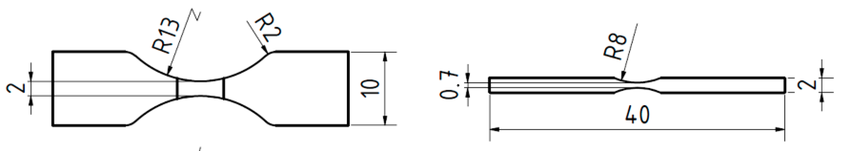
Figure 2.
(a) Design and functional principle of the miniaturized testing device; (b) Installation of the miniaturized testing device into the confocal laser microscope.
Figure 2.
(a) Design and functional principle of the miniaturized testing device; (b) Installation of the miniaturized testing device into the confocal laser microscope.

Figure 3.
(a) Martensite microstructure after heat treatment; ideal {111} pole figure determined according to (b) Kurdjumov–Sachs (K–S) orientation relationship and (c) Nishiyama–Wassermann (N–W) orientation relationship; measured {111} pole figure superimposed with the (d) ideal K–S orientation relationship and (e) the ideal N–W orientation relationship.

Figure 4.
Residual stress profile with corresponding error indicators.
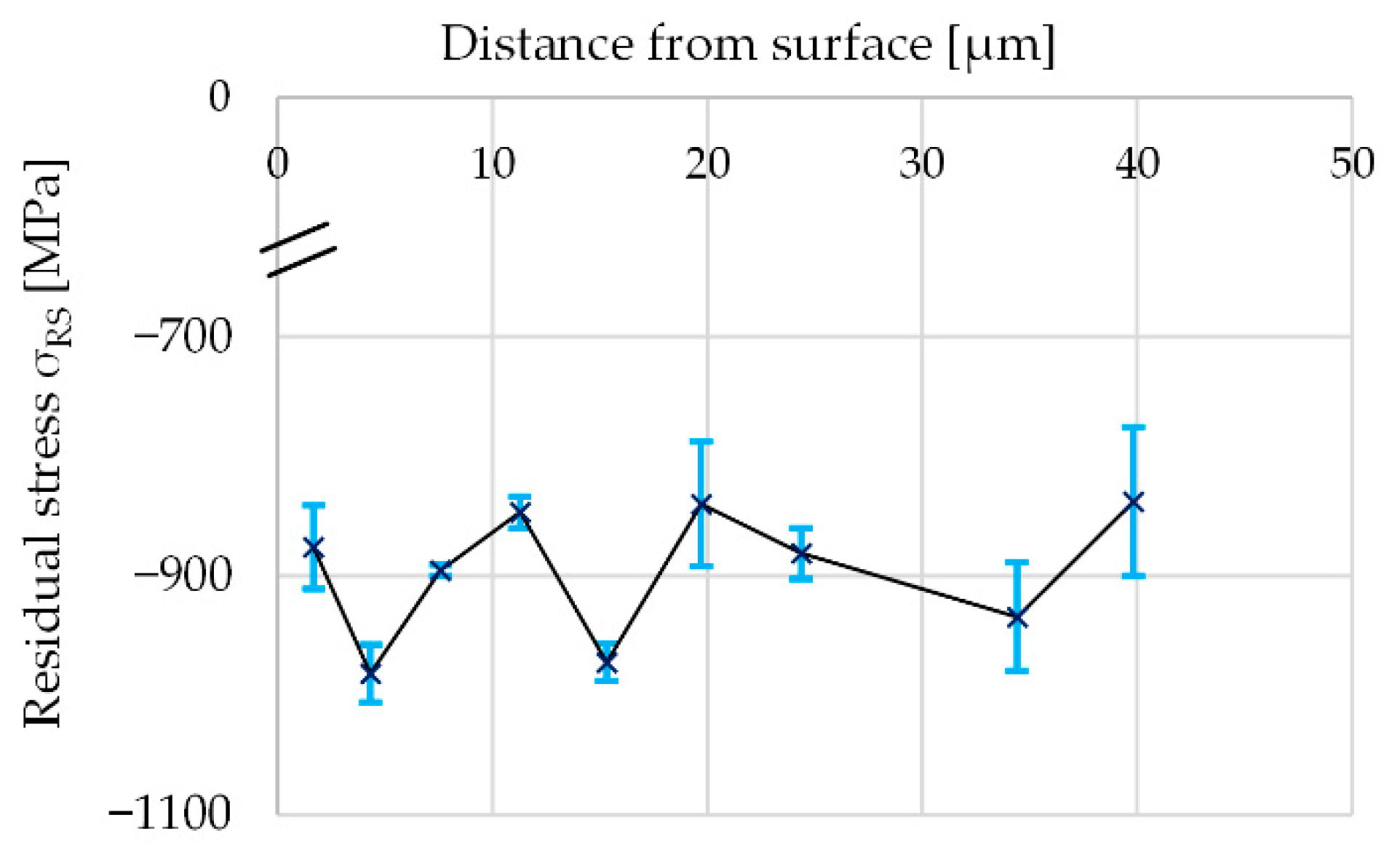
Figure 5.
SEM images of slip bands locally oriented in parallel in an (a) NSP sample, loaded at ∆σ/2 = 680 MPa, recorded after 90,000 loading cycles and (b) an SP sample, loaded at ∆σ/2 = 700 MPa, recorded after 642,030 loading cycles.
Figure 5.
SEM images of slip bands locally oriented in parallel in an (a) NSP sample, loaded at ∆σ/2 = 680 MPa, recorded after 90,000 loading cycles and (b) an SP sample, loaded at ∆σ/2 = 700 MPa, recorded after 642,030 loading cycles.

Figure 6.
(a) Crack density ρCD of the NSP samples and the SP samples as a function of the number of cycles for different stress amplitudes; (b) CLM images of two NSP samples of different stress amplitudes; (c) CLM images of an NSP sample and an SP sample of similar stress amplitude.
Figure 6.
(a) Crack density ρCD of the NSP samples and the SP samples as a function of the number of cycles for different stress amplitudes; (b) CLM images of two NSP samples of different stress amplitudes; (c) CLM images of an NSP sample and an SP sample of similar stress amplitude.
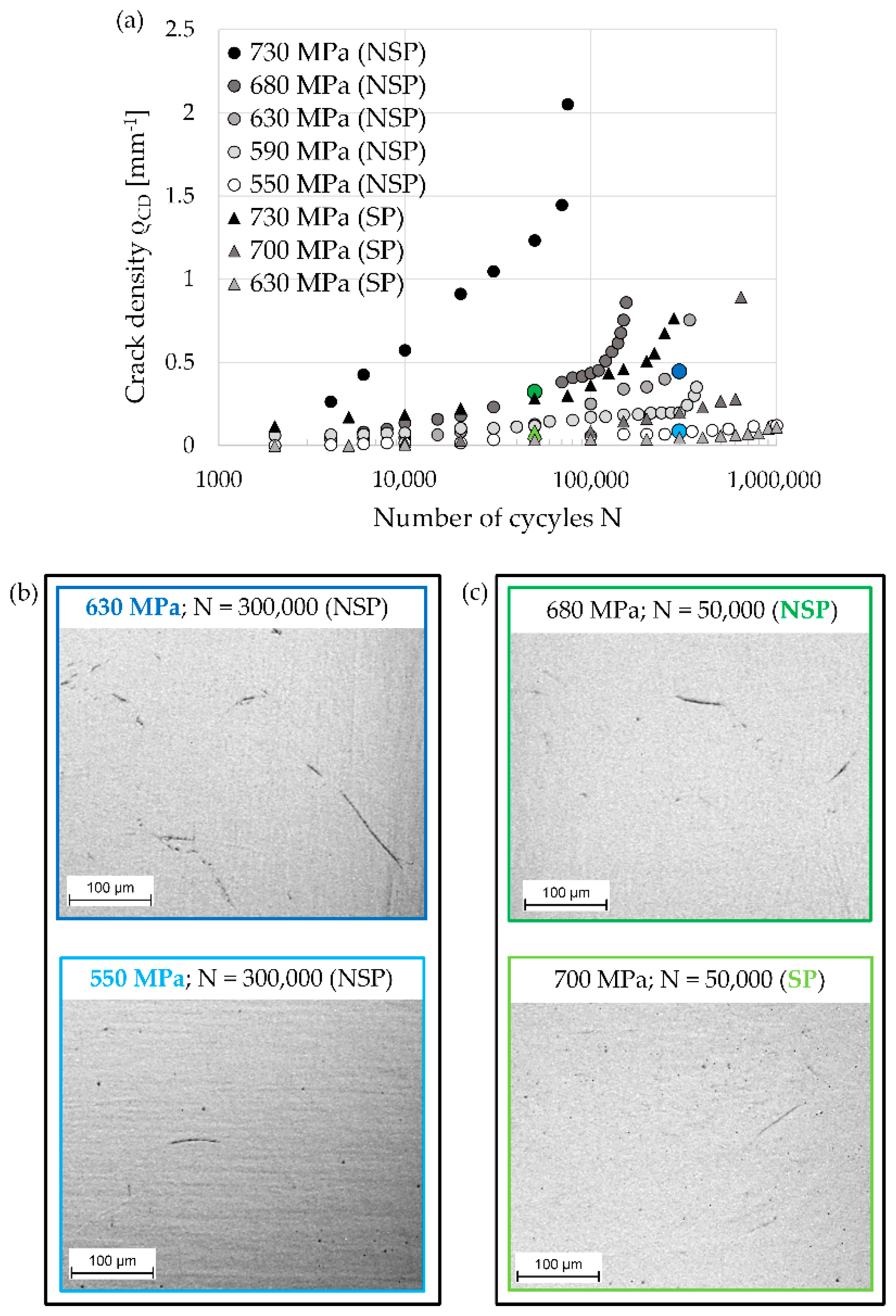
Figure 7.
SEM images of intergranular crack initiation caused by the impingement of slip bands on a PAGB in an (a) NSP sample, loaded at ∆σ/2 = 600 MPa after 90,000 loading cycles, and an (b) SP sample, loaded at ∆σ/2 = 630 MPa after 300,000 loading cycles.
Figure 7.
SEM images of intergranular crack initiation caused by the impingement of slip bands on a PAGB in an (a) NSP sample, loaded at ∆σ/2 = 600 MPa after 90,000 loading cycles, and an (b) SP sample, loaded at ∆σ/2 = 630 MPa after 300,000 loading cycles.

Figure 8.
SEM images of intergranular crack initiation with just one isolated and pronounced slip line at a PAGB in an (a) NSP sample, loaded at ∆σ/2 = 680 MPa after 155,000 loading cycles, and an (b) SP sample, loaded at ∆σ/2 = 730 MPa after 286,120 loading cycles.
Figure 8.
SEM images of intergranular crack initiation with just one isolated and pronounced slip line at a PAGB in an (a) NSP sample, loaded at ∆σ/2 = 680 MPa after 155,000 loading cycles, and an (b) SP sample, loaded at ∆σ/2 = 730 MPa after 286,120 loading cycles.
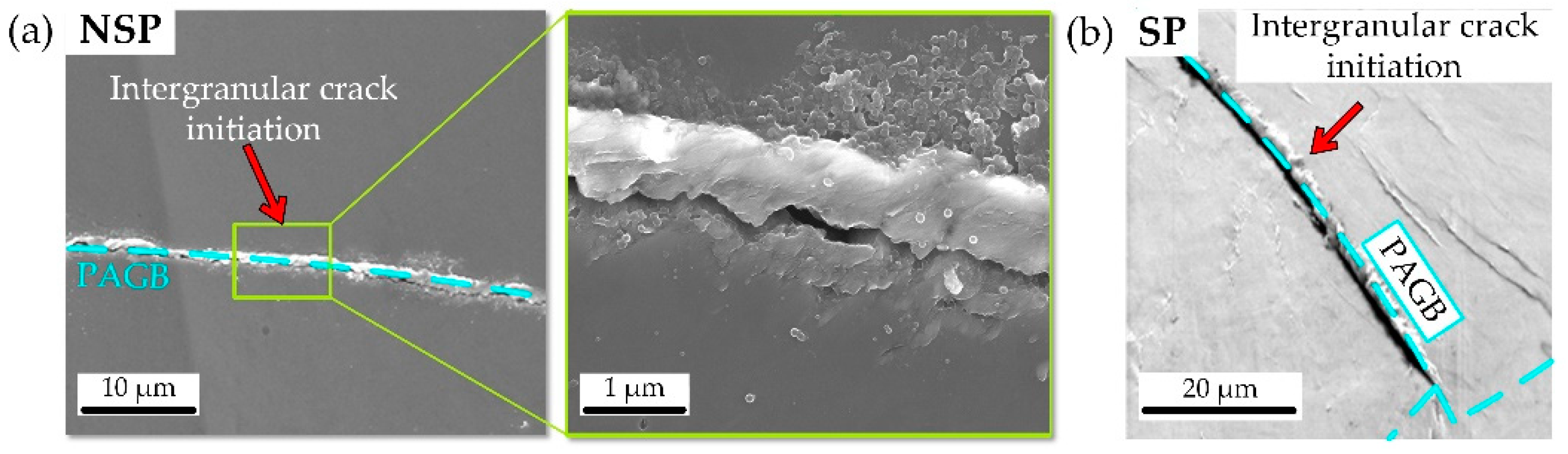
Figure 9.
SEM images of the fracture surfaces of an (a) NSP sample, loaded at ∆σ/2 = 590 MPa for 271,000 loading cycles, and an (b) SP sample, loaded at ∆σ/2 = 730 MPa for 286,120 loading cycles.
Figure 9.
SEM images of the fracture surfaces of an (a) NSP sample, loaded at ∆σ/2 = 590 MPa for 271,000 loading cycles, and an (b) SP sample, loaded at ∆σ/2 = 730 MPa for 286,120 loading cycles.

Figure 10.
EBSD analysis and reconstructed prior austenite grain boundaries of (a) an NSP sample, after 155,000 cycles at Δσ/2 = 680 MPa, and (b) an NSP sample, loaded after 1,000,000 cycles at Δσ/2 = 550 MPa; (c) crack propagation rate as a function of the stress intensity factor. The numbers in the EBSD analysis and the crack propagation curve mark the breakpoints of the cracks.
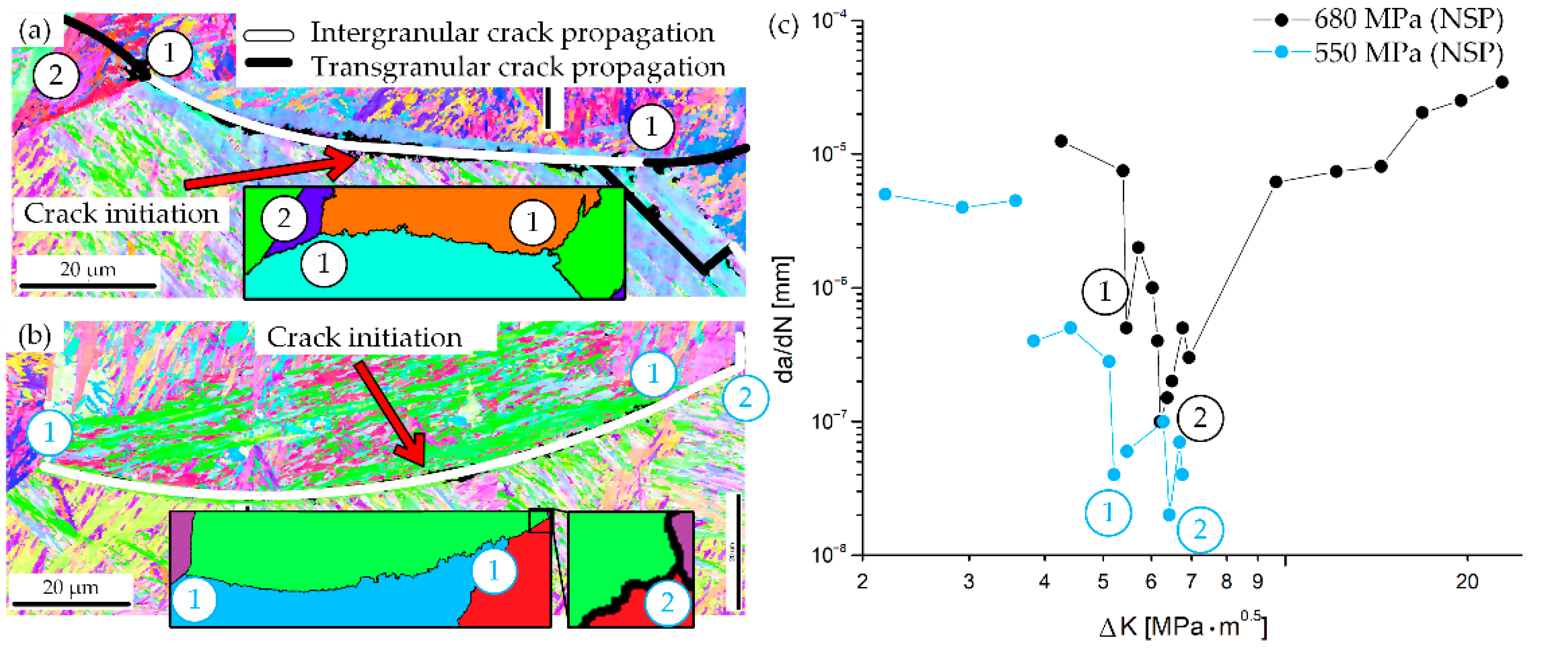
Figure 11.
EBSD analysis with calculated {110} glide plane traces (active glide traces marked in red) and SEM image of an NSP sample after 155,000 cycles at Δσ/2 = 680 MPa. The numbers in the EBSD analysis mark the breakpoints of the crack.
Figure 11.
EBSD analysis with calculated {110} glide plane traces (active glide traces marked in red) and SEM image of an NSP sample after 155,000 cycles at Δσ/2 = 680 MPa. The numbers in the EBSD analysis mark the breakpoints of the crack.
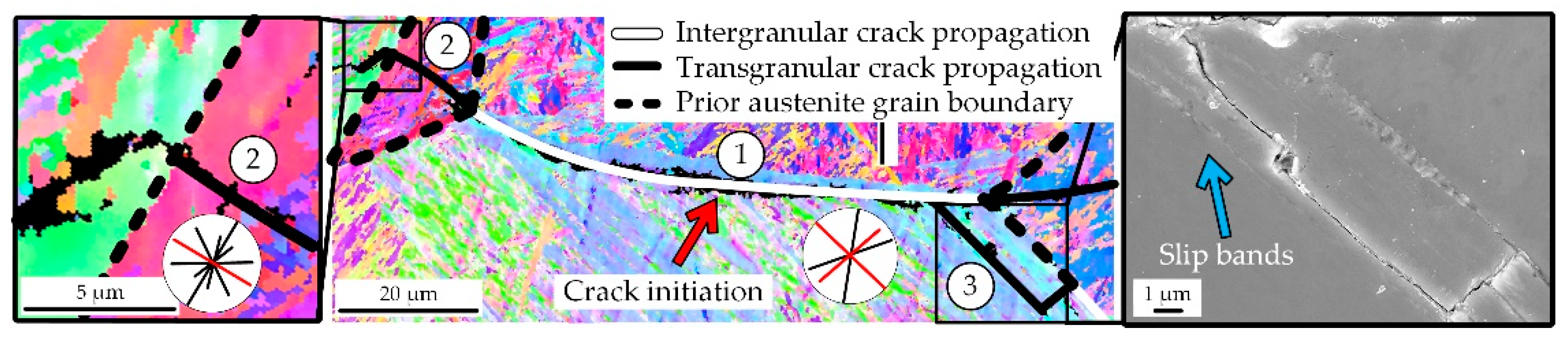
Figure 12.
EBSD analysis with calculated {110} glide plane traces (active glide traces marked in red) and reconstructed prior austenite grain boundaries of an SP sample loaded at Δσ/2 = 630 MPa for 1,000,000 cycles. The numbers in the EBSD analysis mark the breakpoints of the crack.
Figure 12.
EBSD analysis with calculated {110} glide plane traces (active glide traces marked in red) and reconstructed prior austenite grain boundaries of an SP sample loaded at Δσ/2 = 630 MPa for 1,000,000 cycles. The numbers in the EBSD analysis mark the breakpoints of the crack.
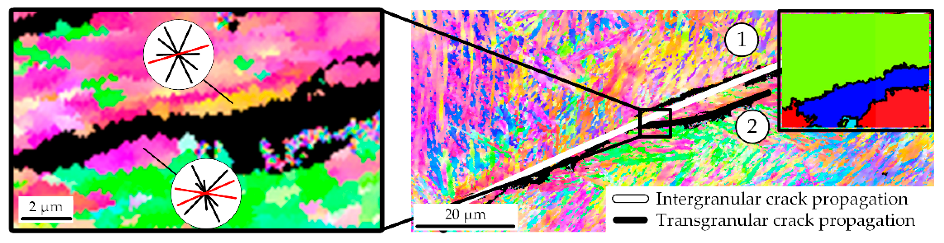
Figure 13.
Crack length of NSP samples as a function of the number of cycles for different stress amplitudes and CLM images of the fatal crack development (marked in blue) divided into short crack propagation and long crack propagation, at Δσ/2 = 680 MPa, for selected cycle numbers.
Figure 13.
Crack length of NSP samples as a function of the number of cycles for different stress amplitudes and CLM images of the fatal crack development (marked in blue) divided into short crack propagation and long crack propagation, at Δσ/2 = 680 MPa, for selected cycle numbers.
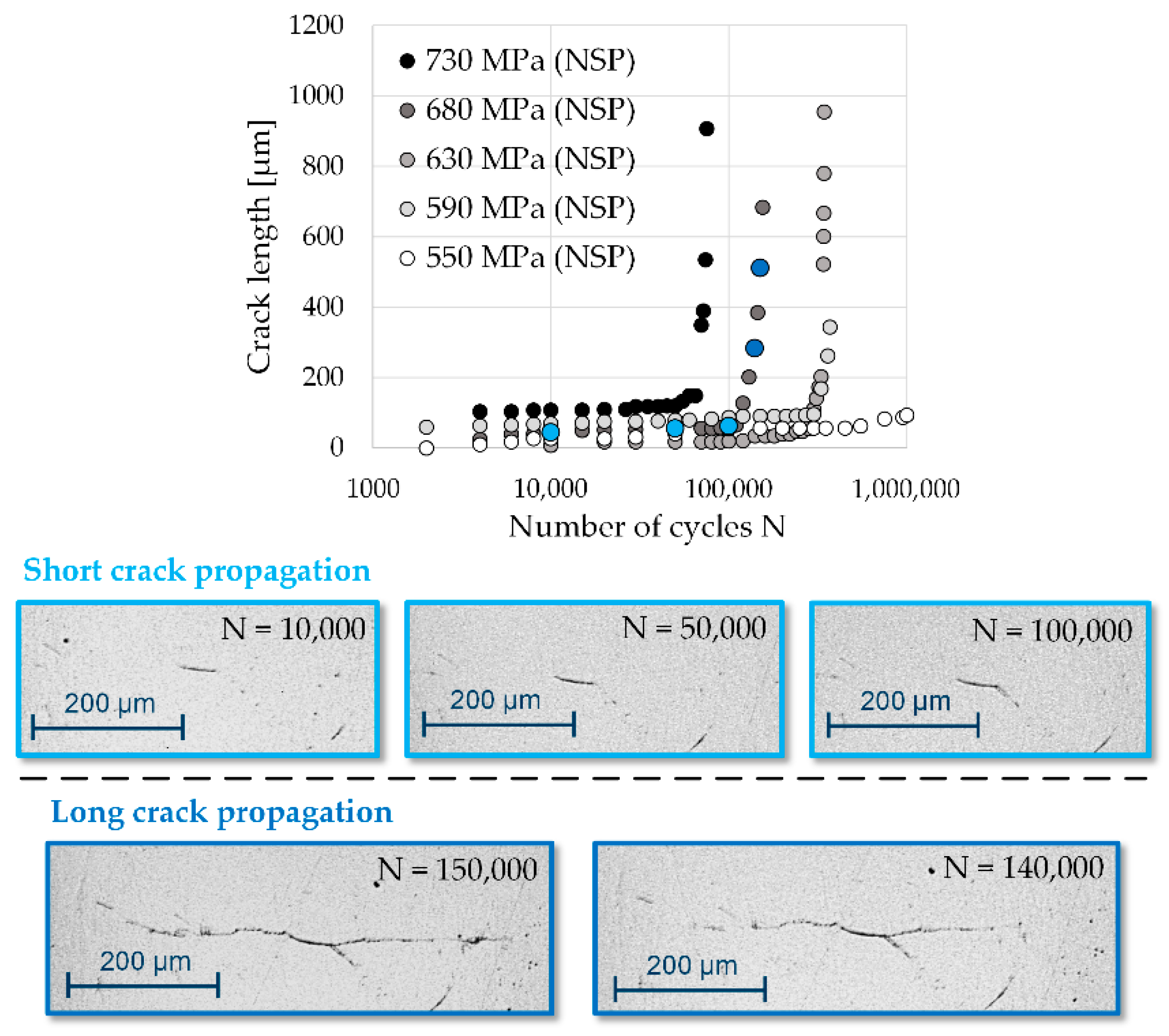
Figure 14.
Number of cycles of the final measuring point as a function of the stress amplitude and additional Subdivision into the stages of crack initiation and short crack propagation, as well as long crack propagation for NSP-samples.
Figure 14.
Number of cycles of the final measuring point as a function of the stress amplitude and additional Subdivision into the stages of crack initiation and short crack propagation, as well as long crack propagation for NSP-samples.


Table 1.
Chemical composition and mechanical properties of SAE 9254 (mass fraction in percent).
| C | Si | Mn | Cr | P | S | UTS [MPa] | YS [MPa] | E [GPa] |
|---|---|---|---|---|---|---|---|---|
| 0.53 | 1.43 | 0.66 | 0.63 | 0.008 | 0.007 | 1750 | 1550 | 210 |
Publisher’s Note: MDPI stays neutral with regard to jurisdictional claims in published maps and institutional affiliations. |
© 2022 by the authors. Licensee MDPI, Basel, Switzerland. This article is an open access article distributed under the terms and conditions of the Creative Commons Attribution (CC BY) license (https://creativecommons.org/licenses/by/4.0/).
Share and Cite
MDPI and ACS Style
Wildeis, A.; Christ, H.-J.; Brandt, R. Influence of Residual Stresses on the Crack Initiation and Short Crack Propagation in a Martensitic Spring Steel. Metals 2022, 12, 1085. https://doi.org/10.3390/met12071085
AMA Style
Wildeis A, Christ H-J, Brandt R. Influence of Residual Stresses on the Crack Initiation and Short Crack Propagation in a Martensitic Spring Steel. Metals. 2022; 12(7):1085. https://doi.org/10.3390/met12071085
Chicago/Turabian StyleWildeis, Anna, Hans-Jürgen Christ, and Robert Brandt. 2022. "Influence of Residual Stresses on the Crack Initiation and Short Crack Propagation in a Martensitic Spring Steel" Metals 12, no. 7: 1085. https://doi.org/10.3390/met12071085
Note that from the first issue of 2016, this journal uses article numbers instead of page numbers. See further details here.