
The Behavior of Ruthenium in Copper Electrowinning

Institute of Nonferrous Metallurgy and Purest Materials, Technische Universität Bergakademie Freiberg, Leipziger Straße 34, 09599 Freiberg, Germany
*
Author to whom correspondence should be addressed.
Metals 2022, 12(8), 1260; https://doi.org/10.3390/met12081260
Submission received: 22 June 2022
/
Revised: 15 July 2022
/
Accepted: 20 July 2022
/
Published: 27 July 2022
(This article belongs to the Special Issue Advances in Understanding Metal Electrolysis Processes)
Abstract
:The recycling of material containing precious metals can lead to the entry of ruthenium into the copper electrowinning process, by so far unknown effects. There, ruthenium is oxidized to highly volatile ruthenium tetroxide. In order to avoid ruthenium losses during electrolysis, the oxidation behavior of ruthenium in copper electrowinning was investigated by testing different oxygen overvoltages using lead alloy and diamond anodes. Furthermore, the temperature and the current density were varied to investigate a possible chemical or electrochemical reaction. The results of the study show that ruthenium is not directly electrochemically oxidized to ruthenium tetroxide at the anode. Especially at anodes with high oxygen overvoltage, the formation of other oxidants occurs parallel to the oxygen evolution in the electrolyte. These oxidants oxidize ruthenium compounds to highly volatile ruthenium tetroxide by chemical reactions. These reactions depend mainly on temperature; the formation of the active oxidants depends on the anodic potential. To avoid ruthenium losses in the copper electrowinning process, anodes with a low anodic potential should be used at low electrolyte temperatures.
1. Introduction
Ruthenium is used primarily as a wear-resistant, electrically highly conductive layer on contacts in electronic components. Ruthenium oxides also have a catalytic effect and are used as catalysts in the synthesis of ammonia and as coatings for dimensionally stable anodes in metal electrowinning. The global production of ruthenium was 33 tons in the year 2018. The primary production of ruthenium is based mainly on the production of other platinum group metals, as well as copper or nickel. In order to become more independent from primary production for the increasing demand of ruthenium, there will be an increased focus on recycling in the future [1].
One possible recycling route of material containing ruthenium (e.g., used catalysts from the chemical industry) is shown in Figure 1. During a thermal process, the raw material containing precious metals is melted together with copper, which is a collector for precious metals. The non-precious metals contained in the raw material, such as Pb, As, or Sb, are separated in a slag. Afterwards, the copper and the precious metals are separated from each other by an oxidative leaching in sulfuric acid at high temperatures and high oxygen partial pressure. During this process step, copper is leached and the precious metals are collected, undissolved, in a residue from which the precious metals can be recovered. The copper from the leaching solution will be recovered by a subsequent winning electrolysis.
Our experimental studies on oxidative leaching with sulfuric acid showed that depending on the leaching parameters, a portion of the ruthenium enters into the solution together with copper. In the subsequent copper electrowinning, ruthenium is partially oxidized to the highly volatile and toxic ruthenium tetroxide, which leads to losses of ruthenium and thus, to a lower recycling rate for this product. No systematic studies on ruthenium behavior in copper electrowinning have been described in the literature so far. Therefore, the oxidation behavior of ruthenium in copper winning electrolysis was systematically investigated, and suggestions for avoiding the emission of ruthenium tetroxide were derived.
2. Literature Evaluation
2.1. Chemistry of Ruthenium
Since the chemistry of ruthenium is very complex, the chemical and electrochemical behavior of ruthenium will only be briefly summarized here. Ruthenium can take oxidation states between −II to +VIII, due to its electron configuration [Kr] 4d6 5s2. The oxidation states +II, +III, +IV, and +VIII are stable. Due to the strong tendency of ruthenium to form complexes, the redox potentials are often presented only for the Ru-H2O system. In their work, Povar and Spinu [3,4] present a potential-pH diagram for the Ru-H2O system for a ruthenium concentration of 10−4 mol/L. In sulfuric acid electrolytes of copper electrowinning, the pH is usually between −0.5 and +0.5. In this range, ruthenium is oxidized to the VIII-valent stage via valence stages II, III, and IV. For copper electrowinning conditions, ruthenium is expected to be oxidized to Ru(IV) in an acidic copper sulfate electrolyte under standard conditions at about 0.8 V, and then to Ru(VIII) at potentials above the potential for oxygen formation. The +VI and +VII oxidation states of ruthenium are thermodynamically stable only in the neutral and alkaline pH range, respectively. In strongly acidic solutions, disproportionation to Ru(IV) and Ru(VIII) compounds occurs. The primary formed compound H2RuO5, according to thermodynamic calculations, reacts to the highly volatile RuO4 (boiling point 40 °C), which partially evaporates under the conditions of copper electrowinning. The electrochemical reduction of RuO4 in sulfuric acid solution is said to form the green intermediate RuO22+, which disproportionates afterwards over a period of several hours to form Ru(IV) and Ru(VIII) [5].
In sulfuric acid electrolytes, ruthenium can form sulfate complexes. The chemistry of ruthenium sulfate complexes includes simple sulfates, as well as polynuclear structures [6].
Jaskula [7] summarizes the literature on the behavior of platinum group metals in copper electrowinning. For the dissolution of ruthenium from a copper anode containing 0.4% Ni and 0.4% Ru, chloride ions are conducive to the formation of ruthenium chloro-complexes. At a current density of 240 A/m², about 67% of the ruthenium goes into the solution, about 28% collects in the anode slime, and 3–4% is deposited cathodically along with the copper. The low ruthenium concentration in the copper cathodes is an indication that ruthenium is bound in a stable complex in the electrolyte. Cathodic deposition of ruthenium from a solution is only possible if the oxidation state of ruthenium in the solution is less than +IV.
The behavior of ruthenium under the conditions of copper electrowinning has not been studied so far. However, it is described that Ru(III) is oxidized to Ru(VI) in a sulfuric acid solution using a gold electrode [8]. Ru(VI) then disproportionates to form Ru(IV) and Ru(VIII). If the anodic potential is higher, Ru(III) should be further oxidized via Ru(VI) to Ru(VIII) on a gold, platinum, or palladium electrode in a sulfuric acid solution. This process is promoted by the presence of chloride ions [9]. In sulfuric acid solutions, Ru(VIII) is soluble, but readily volatile due to its low boiling point, and it evaporates from the electrolyte as gaseous RuO4 at the appropriate temperature [3].
2.2. Processes on Insoluble Anodes for Metal Electrowinning
For metal electrowinning from sulfuric acid electrolytes, anodes made of lead alloys are usually used. Under current flow, Pb2+ ions may go into the solution and react with SO42− ions to form poorly soluble PbSO4. The PbSO4 completely covers the anode surface and has a passivating effect, so that the potential at the anode increases sharply. Once the anodic potential at which the PbSO4 converts to an electron-conducting PbO2 layer is reached, oxygenation occurs. The advantage of lead compared to other anode materials is the self-healing effect of the conductive layer, when it is destroyed mechanically. However, lead anodes have a relatively high oxygen overvoltage. By the selective addition of alloying elements, such as Ag, in production of the anodes, the oxygen overvoltage can be lowered compared to that of pure lead. Another disadvantage is the low mechanical stability of lead anodes. This can be improved by alloying elements such as Ca. PbSnCa anodes have a relatively high oxygen overvoltage, but due to their good mechanical stability, they are currently the anode of choice for copper electrowinning [11].
Depending on the anodic potential, other oxidants besides oxygen can be formed at the anodes in the sulfuric acid electrolyte, with significantly higher electropositive potentials compared to oxygen (see Table 1). While the radicals and atomic oxygen only have very short lifetimes, ozone, hydrogen peroxide, and peroxodisulfate are relatively stable compounds. Due to their high oxidation potentials, they are able to oxidize ruthenium to RuO4. Compared to peroxodisulfate, ozone has only a low solubility in sulfuric acid solutions, and hydrogen peroxide decomposes quickly due to the catalytic effect of Cu(II) ions in the electrolyte, even at room temperature [12].
3. Investigation of the Oxidation of Ruthenium in Copper Electrowinning
3.1. Experimental Setup and Experimental Procedure
Figure 2 schematically shows the experimental setup for performing copper electrowinning. Copper electrowinning was operated in a 2.1 L polypropylene cell. The cell had an inlet and an outlet box. The inlet was located at the bottom of the cell, so that the electrolyte entered at the bottom of the cell, ensuring a complete exchange of the electrolyte. An overflow in the drain box ensured a constant electrolyte level in the cell. Since it was not possible to equalize the copper concentration without influencing the redox processes in the electrolyte, the experiments were carried out with small electrodes (50 mm × 120 mm) and a large electrolyte volume. An Erlenmeyer flask was used to increase the electrolyte volume. The entire apparatus had a capacity of 5 L. To ensure a constant electrolyte temperature, the Erlenmeyer flask was placed in a water bath, which was temperature controlled by a thermostat. To compensate the water that evaporated during the experiments, a Mariotte bottle, in the form of a sheath funnel closed at the top, was immersed in the drain box (not shown in Figure 2). The added deionized water directly entered the pump from the drain box, thus realizing an immediate mixing with the electrolyte.
The starting electrolyte contained 40 g Cu(II)/L, 180 g free H2SO4/L, and about 100 mg Ru(III)/L. Ruthenium was added to the electrolyte as RuCl3⋅xH2O powder 30 min before the start of each electrolysis.
The ruthenium concentration in the electrolyte was determined by atomic adsorption spectrometry (AAS). According to our own extensive investigations [13], the electrolyte samples were prepared as follows: Directly after obtaining the sample, an excess of Fe2+ ions were added, because higher oxidized ruthenium compounds (such as oxidation states VI to VIII) can be atomized more easily compared to Ru(III) [14]. Ru(III) was the oxidation state of ruthenium in the calibration solution. Hence, the ferrous ions reduce the higher oxidized ruthenium compounds, making them equal to the oxidation state of ruthenium in the calibration solution.
As mentioned above, ruthenium chloride powder was added to adjust the ruthenium concentration in the electrolyte. This means that in addition to ruthenium, chloride ions were also present in the electrolyte. Systematic tests without chloride ions in the electrolyte were not performed, because scanning tests with a chloride-free electrolyte showed that the influence of chloride ions on the oxidation of ruthenium is insignificant. Moreover, no additives were added, to avoid their possible complexation with ruthenium.
The duration of electrolysis was selected in such a way that at the end of the experiments, the copper concentration did not fall below 20 g/L. During electrolysis, the anode potential was measured continuously with a copper wire inside a Luggin capillary, the redox potential was measured with a platinum redox electrode, and then it was converted to the standard hydrogen potential. A stainless steel sheet of V2A (X5CrNi18-10) was used as a cathode. The distance between the anode and the cathode was 30 mm. The temperature (22.5 °C, 40 °C, 60 °C), the current density (100 A/m², 240 A/m², 500 A/m²), and the level of the anode potential were investigated as the main variables influencing the oxidation of the ruthenium. For the variation of the anode, potential experiments were carried out with different anode materials. The PbSn1.3Ca0.07 anode, which is typically used in copper electrowinning, a PbAg0.5 anode, generally used in zinc electrowinning, and a boron-doped diamond anode were used.
The ruthenium oxidation was evaluated by concentration-time curves of ruthenium. Due to the inhomogeneity of RuCl3⋅xH2O, the starting concentration of ruthenium deviated up to 20 mg/L, in some cases, from the desired target concentration of 100 mg/L. For better comparability of the experiments, the concentrations of ruthenium were related to the starting concentration, so that the relative change in ruthenium concentration is given.
During copper electrolysis, the ruthenium concentration decreased because RuO4 is volatilized, which occurs due to the oxidation of Ru(III). Thus, the concentration-time curves are dominated by the rate of oxidation of ruthenium to RuO4. Pre-conditions for this assumption are that the volatilization of RuO4 is not the rate-determining step in the process, and that the amount of cathodically deposited ruthenium can be neglected. Since the ruthenium concentration in the cathodes was always <10 µg/g, the amount of cathodically deposited Ru could be neglected.
3.2. Influence of Current Density
Assuming that ruthenium oxidation occurs electrochemically at the anode, the oxidation rate should increase with current density. Presently, most copper electrowinning operates at current densities between 230 A/m² and 450 A/m², although depending on the technology, current densities can sometimes be even higher or lower. The studies on the influence of current density were carried out at 100, 240, and 500 A/m² with PbSn1.3Ca0.07 anodes at 40 °C. As Figure 3 shows, the curves for ruthenium concentrations at 100 and 240 A/m² are almost identical, while at 500 A/m², the ruthenium concentrations decrease much faster. Figure 3 further shows that the redox potential increases from approx. 0.95 V to 1.2–1.3 V in all experiments at the start of electrolysis, and then remains constant. The reduction of the ruthenium concentrations begins first at a redox potential >1.1 V. This relationship also occurred in all other experiments. In the electrolysis with 100 and 240 A/m², the anode potential was almost identical with 2.07 and 2.08 V, respectively, while it was slightly higher with 2.23 V at 500 A/m². The influence of the anode potential on the rate of ruthenium oxidation is discussed in more detail in Section 3.4.
3.3. Influence of Temperature
The investigations on the influence of current density on the rate of ruthenium oxidation indicate that the oxidation of ruthenium does not occur at the anode, but by subsequent chemical reactions in the electrolyte. In this case, the ruthenium concentration in the electrolyte must decrease more rapidly at higher temperatures. Figure 4 shows an example of the curve progressions of the relative ruthenium concentration, the anode potential, and the redox potential as a function of temperature during electrolysis with a PbSnCa anode at 240 A/m². It was found that at higher electrolyte temperatures, the ruthenium concentration in the electrolyte decreases much more quickly and after a shorter time. Investigations with the PbAg anode and the diamond anode confirm the strong influence of temperature on both the beginning and the velocity of the oxidation rate.
At higher temperatures, the anode potential increases faster at the start of electrolysis. Independent from temperature and anode material, the redox potential was between 1.2 and 1.3 V for the balance of the time of electrolysis. The anode potential decreased by 10 to 20 mV for all three anode materials when the temperature was increased from 22.5 to 60 °C.
The reaction rates were calculated from the linear section of the concentration-time curves and from these, the activation energy was calculated via the Arrhenius equation. The activation energy of the ruthenium oxidation using different anode materials is between 35–38 kJ/mol. Independent of the anode material, the oxidation mechanism of ruthenium is chemically controlled, and it seems to be similar for all tested anode materials.
3.4. Influence of the Anode Potential
For the investigations of the influence of the anode potential, experiments were carried out with a PbSn1.3Ca0.07 anode, a PbAg0.5 anode, and a boron-doped diamond anode. The anode potential of the PbSnCa anode ranged from 2.0 to 2.2 V, depending on the current density and temperature; the potential of the PbAg anode, in comparison, was approx. 80 mV lower, and that of the diamond anode was approx. 700 mV higher. Figure 5 shows an example for the current density of 240 A/m² and a temperature of 60 °C; the ruthenium concentrations in the electrolyte drop significantly faster at higher anode potentials.
The reaction rate was calculated using the linear section of the concentration-time curves. As Figure 6 shows, there is a linear relationship between the anode potential and the oxidation rate of ruthenium for all three temperatures. Again, the strong influence of temperature on the oxidation rate can be clearly seen. The straight line at 40 °C also shows the results of the experiments with current densities of 100 and 500 A/m². These also fit onto the straight line. Consequently, the current density has no significant influence on the oxidation rate.
4. Studies on the Oxidants Formed at the Anode
The electrolysis experiments showed that, simultaneously with the oxidation of ruthenium, other oxidants are formed at the anode in addition to oxygen, and those oxidants are able to oxidize ruthenium to the VIII-valent stage. In a further series of experiments, therefore, the electrochemical formation of those oxidizing agents and the subsequent oxidation reactions of the ruthenium were investigated.
4.1. Experimental Setup and Experimental Procedure
Especially at anodes with a high oxygen overvoltage, various other oxidants beside oxygen are formed, but they cannot be identified in detail [15]. However, it is possible to determine the molar amount quantitatively. For this determination, electrolysis tests were conducted with an electrolyte (40 g Cu/L and 180 g H2SO4/L) without ruthenium. The samples were taken directly in front of the anode surface and added immediately to an excess of Fe2+ solution to reduce the contained oxidants [16]. Afterwards the surplus Fe2+ ions were back titrated by means of a Ce(IV)-sulphate solution and subsequently, the molar amount of oxidants was calculated. The molar amount is indicated as mmol/l, calculated theoretically for a one-electron-transfer.
Tentative tests show that the molar amount of anodically formed oxidants is too low for a quantitative determination at anodes made of lead alloys. Therefore, the investigations were performed using the diamond anode, with a variation of the temperature (22.5 °C, 40 °C, 60 °C) and the current density (100 A/m², 240 A/m², 500 A/m²).
4.2. Results
In Figure 7, the temporal progression of the molar concentration of the anodically formed oxidants is shown during electrolysis using a diamond anode at 40 °C. At the beginning of each experiment, the concentration of the anodically formed oxidants increases almost linearly. At high current density, the concentration increases faster compared to the rate at a low current density. The formation of the oxidants at the anode is apparently an electrochemical reaction. Later, the curves flatten, and the molar concentration remains nearly at a certain value after 34 h, for example, at 500 A/m². Because of the curve progressions, it seems that either the anodically formed oxidants decompose in the electrolyte, or they are reduced cathodically under the copper electrowinning conditions. It can be assumed that both processes occur in parallel. Consequently, an equilibrium between the electrochemical formation and the decomposition is established.
The influence of temperature on the molar concentration of the anodically formed oxidants at 240 A/m² is shown in Figure 8. At the start of each experiment, the molar concentration seems to be similar at all tested temperatures. A similar amount of oxidants is formed at the anode at the same current density, which is another evidence for the electrochemical formation of the oxidants. In the further progress of the curve (with higher molar concentration of anodically formed oxidants), the formation is compensated by the decomposition. This decomposition is a temperature-dependent reaction in the electrolyte, as well as a back solution (by oxidation) of the cathodic copper. An increase in the temperature to 60 °C during electrolysis accelerates the decomposition reaction, as well as the back solution of the cathodic copper. This is the reason why the equilibrium between the formation and the decomposition of the anodically formed oxidants is already achieved after approx. 24 h at 60 °C. At room temperature, the decomposition and the back solution of the cathodic copper does not occur this quickly; hence, equilibrium is not achieved during the test.
To investigate the stability of the anodically formed oxidants, the current was switched off after 24 h of electrolysis. From this point on, the concentration of the oxidants decreased. At higher temperatures, the concentration decreased much faster. The reaction rate was calculated from the concentration-time curves, and the activation energy was calculated via the Arrhenius equation [13]. In the electrolysis cell, the decomposition of the oxidant proceeded according to a first-order reaction, with an activation energy of 44 kJ/mol. In contrast, when the electrolyte was stored at 22.5 °C and metallic copper was absent, the concentration of the oxidant remained constant for several days.
It is described in the literature that during electrolysis with diamond anodes in sulfuric acid electrolytes, sulfate is anodically oxidized to peroxodisulfate [17]. Since a direct determination of low concentrations of peroxodisulfate in sulfuric acid electrolytes was not possible using our analytical methods, the oxidation behavior and stability of the electrolytes containing the anodically produced oxidant were compared to electrolytes containing the same concentration of sodium peroxodisulfate under the same conditions. For preparation of the oxidant-containing solution, electrowinning with synthetic electrolytes without ruthenium was carried out using a diamond anode. The concentration of this oxidant was determined by titration. The concentration was 35 mmol/L. The reference solution with sodium peroxodisulfate was prepared by adding the appropriate amount of sodium peroxodisulfate to a synthetic copper electrolyte, which was not treated electrochemically.
Graduated amounts of these solutions (0 µL to 1000 µL) were added to each 10 mL sample containing a sulfuric acid copper electrolyte with 90 mg Ru(III)/L. All samples were stored in sealed plastic containers for 24 h at 80 °C. Preliminary experiments showed that during this time, the oxidation reaction of ruthenium was fully completed. During the tests, the primary formed ruthenium tetroxide was reduced on the plastic coating of the vessels and deposited there as RuO2. The ruthenium concentration in the solution was analyzed, and the amount of oxidized ruthenium was calculated therefrom. As Figure 9 shows, the curves for both solutions are almost identical.
Comparative studies on the stability of the anodically formed oxidant and peroxodisulfate in an electrolytic cell showed almost identical behavior as well [13]. This confirms that in copper electrowinning, sulfate ions are oxidized to peroxodisulfate ions at the anodes at potentials above 2 V, and afterwards, they can subsequently oxidize ruthenium ions in the electrolyte to the VIII-valent stage and thus to the highly volatile RuO4.
5. Summary of Results and Conclusions for Copper Electrowinning Process
In this work, systematic investigations were carried out on the behavior of ruthenium in copper electrowinning. Depending on the electrolysis parameters, some ruthenium is oxidized to the VIII-valent stage and volatilized subsequently as RuO4. This leads to ruthenium losses. The studies indicate that at anode potentials above 2 V, sulfate ions are oxidized to peroxodisulfate ions at the anode. These subsequently oxidize the ruthenium in the electrolyte to the VIII-valent stage. The main variables influencing the rate of ruthenium oxidation are the level of the anode potential and the temperature.
A linear correlation between the oxidation rate of ruthenium and the anodic potential was found. Since the oxidation of ruthenium is chemically controlled, the reaction, and thus the decrease in the ruthenium concentration in the electrolyte, becomes faster at higher temperatures. An increase in current density leads to an increasing formation of oxidants at the anode, but this only results in a slight increase in the oxidation rate of ruthenium. Obviously, the rate-limiting step is not the formation of the oxidants at the anode, but the following reaction with ruthenium. Peroxodisulfate, which is formed at the anode during copper electrowinning, is not stable, and therefore, an equilibrium between the formation and the decomposition is achieved during the progress of electrolysis.
The following options exist for minimizing ruthenium losses during the recycling of precious metals:
- Improving the conditions concerning the dissolution of ruthenium during oxidative leaching in sulfuric acid, hence minimizing the entry of ruthenium into copper electrowinning.
- Running the copper electrowinning at low temperatures and with low anodic potentials, using anode materials with a low oxygen overvoltage, as well as using additives that decrease the anodic potential (such as Co(II)).
- Adding easily oxidizable compounds to the electrolyte, e.g., ascorbic acid or Fe2+ ions were already realized [13], which are oxidized by anodically formed oxidants before ruthenium.
If these options prevent the formation of volatile ruthenium tetroxide, ruthenium accumulates in the electrolyte. To remove it, the ruthenium must then be oxidized to the volatile RuO4 in a separate process in a partial stream of the electrolyte by adding strong oxidizing agents, such as sodium peroxodisulfate, hydrogen peroxide, or ozone, and then separated from the waste gas in a washing process, e.g., with a hydrochloric acid ethanol solution [13,18].
Author Contributions
Conceptualization, A.T. and H.B.; methodology, A.T. and H.B..; validation, A.T.; formal analysis, A.T.; investigation, A.T.; resources, M.S.; data curation, A.T.; writing—original draft preparation, A.T.; writing—review and editing, H.B. and M.S.; visualization, A.T.; supervision, M.S.; project administration, A.T.; funding acquisition, M.S. All authors have read and agreed to the published version of the manuscript.
Funding
This research was partially funded by Umicore NV/SA, Brussels, Belgium.
Data Availability Statement
Data sharing is not applicable.
Acknowledgments
We thank Umicore for the financial and material support for this research.
Conflicts of Interest
The authors declare no conflict of interest.
References
- Marscheider-Weidemann, F.; Langkau, S.; Eberling, E.; Erdmann, L.; Haendel, M.; Krail, M.; Loibl, A.; Neef, C.; Neuwirth, M.; Rostek, L.; et al. DERA Rohstoffinformationen, Rohstoffe für Zukunftstechnologien 2021; DERA Rohstoffinformationen 50; DERA: Berlin, Germany, 2021; pp. 20–21. ISBN 978-3-948532-47-5. [Google Scholar]
- Hagelüken, C. Recycling of electronic scrap at Umicore—Precious metals refining. Acta Metall. Slovaca 2006, 12, 111–120. [Google Scholar]
- Povar, I.; Spinu, O. Ruthenium redox equilibria, 2. Thermodynamic analysis of disproportionation and comproportionation conditions. J. Electrochem. Sci. Eng. 2016, 6, 135–143. [Google Scholar] [CrossRef] [Green Version]
- Povar, I.; Spinu, O. Ruthenium redox equilibria, 3. Pourbaix diagrams for the systems Ru-H2O and Ru-Cl-H2O. J. Electrochem. Sci. Eng. 2016, 6, 145–153. [Google Scholar] [CrossRef] [Green Version]
- Seddon, E.A.; Seddon, K.R. The Chemistry of Ruthenium, 1st ed.; Elsevier Science Publishers B.V.: Amsterdam, The Netherlands, 1984. [Google Scholar]
- Rard, J.A. Chemistry and Thermodynamics of Ruthenium and some of its Inorganic Compounds and Aqueous Species. Chem. Rev. 1985, 85, 1–39. [Google Scholar] [CrossRef]
- Jaskula, M. Das Verhalten der Platinmetalle während der Kupferraffinationselektrolyse. Erzmetall 1989, 42, 117–124. [Google Scholar]
- Gmelin-Institut. Gmelins Handbuch der Anorganischen Chemie, 8th ed.; Verlag Chemie: Weinheim, Germany, 1970; Volume 63. [Google Scholar]
- Yoshii, K.; Hideo, Y.; Histeru, O. The electrodeposition of ruthenium from a ruthenium (III) and ruthenium (IV) solution and a fission products solution. Bull. Chem. Soc. Jpn. 1965, 38, 1911–1915. [Google Scholar] [CrossRef] [Green Version]
- Remy, H. Lehrbuch der Anorganischen Chemie, 10th ed.; Geest & Portig: Leipzig, Germany, 1959. [Google Scholar]
- Stelter, M.; Hein, K.; Bauer, I. Neue Bleianodenwerkstoffe für die Metallgewinnungselektrolyse. Erzmetall 1998, 51, 281–289. [Google Scholar] [CrossRef]
- Hollemann, A.F.; Wiberg, E.; Wiberg, N. Lehrbuch der Anorganischen Chemie, 102nd ed.; Walter de Gruyter: Berlin, Germany, 2007; pp. 1666–1680. [Google Scholar]
- Thiere, A. Ein Beitrag zum Oxidationsverhalten von Ruthenium Während einer Kupfergewinnungselektrolyse. Ph.D. Thesis, Technische Universität Bergakademie Freiberg, The University of Ressources, Freiberg, Germany, 2018. [Google Scholar]
- Benzo, Z.; Salas, J.; Araujo, P.; Camardiel, A.; Carrión, N. Estimination of experimental parameters for the determination of ruthenium by flame atomic absorption spectroscopy. Chemom. Intell. Lab. Syst. 1998, 40, 109–117. [Google Scholar] [CrossRef]
- Soni, B.D.; Patel, U.D.; Agrawal, A.; Ruparelia, J.P. Application of BDD and DSA electrodes for the removal of RB 5 in batch and continuous operation. J. Water Process Eng. 2017, 17, 11–21. [Google Scholar] [CrossRef]
- Waclawek, S.; Lutze, H.V.; Grübel, K.; Padil, V.V.T.; Černík, M.; Dionysiou, D.D. Chemistry of persulfates in water and wastewater treatment: A review. Chem. Eng. J. 2017, 330, 44–62. [Google Scholar] [CrossRef]
- Serrano, K.; Michaud, P.A.; Comninellis, C.; Savall, A. Electrochemical preparation of peroxodisulfuric acid using boron doped diamond thin film electrodes. Electrochim. Acta 2002, 48, 431–436. [Google Scholar] [CrossRef] [Green Version]
- Thiere, A. Behaviour of Ruthenium in Copper Electrowinning. Diploma Thesis, Technische Universität Bergakademie Freiberg, The University of Ressources, Freiberg, Germany, 2014. [Google Scholar]
Figure 1.
Recycling process for materials containing precious metals (PM), (simplified and modified according to [2]).
Figure 1.
Recycling process for materials containing precious metals (PM), (simplified and modified according to [2]).
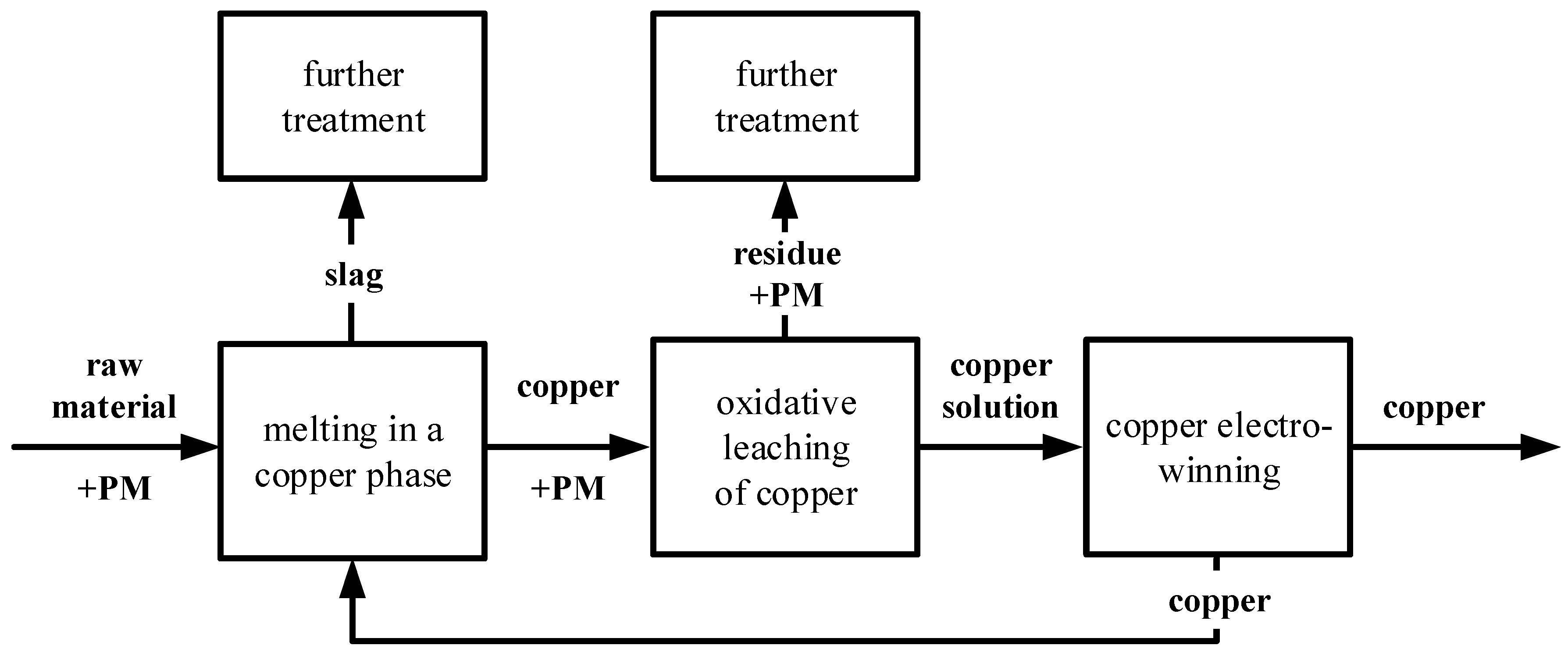
Figure 2.
Experimental setup.

Figure 3.
Relative ruthenium concentration (crel(Ru)), anodic potential (Ua), and redox potential (Ured) at different current densities during an electrolysis with a PbSnCa anode at 40 °C.
Figure 3.
Relative ruthenium concentration (crel(Ru)), anodic potential (Ua), and redox potential (Ured) at different current densities during an electrolysis with a PbSnCa anode at 40 °C.
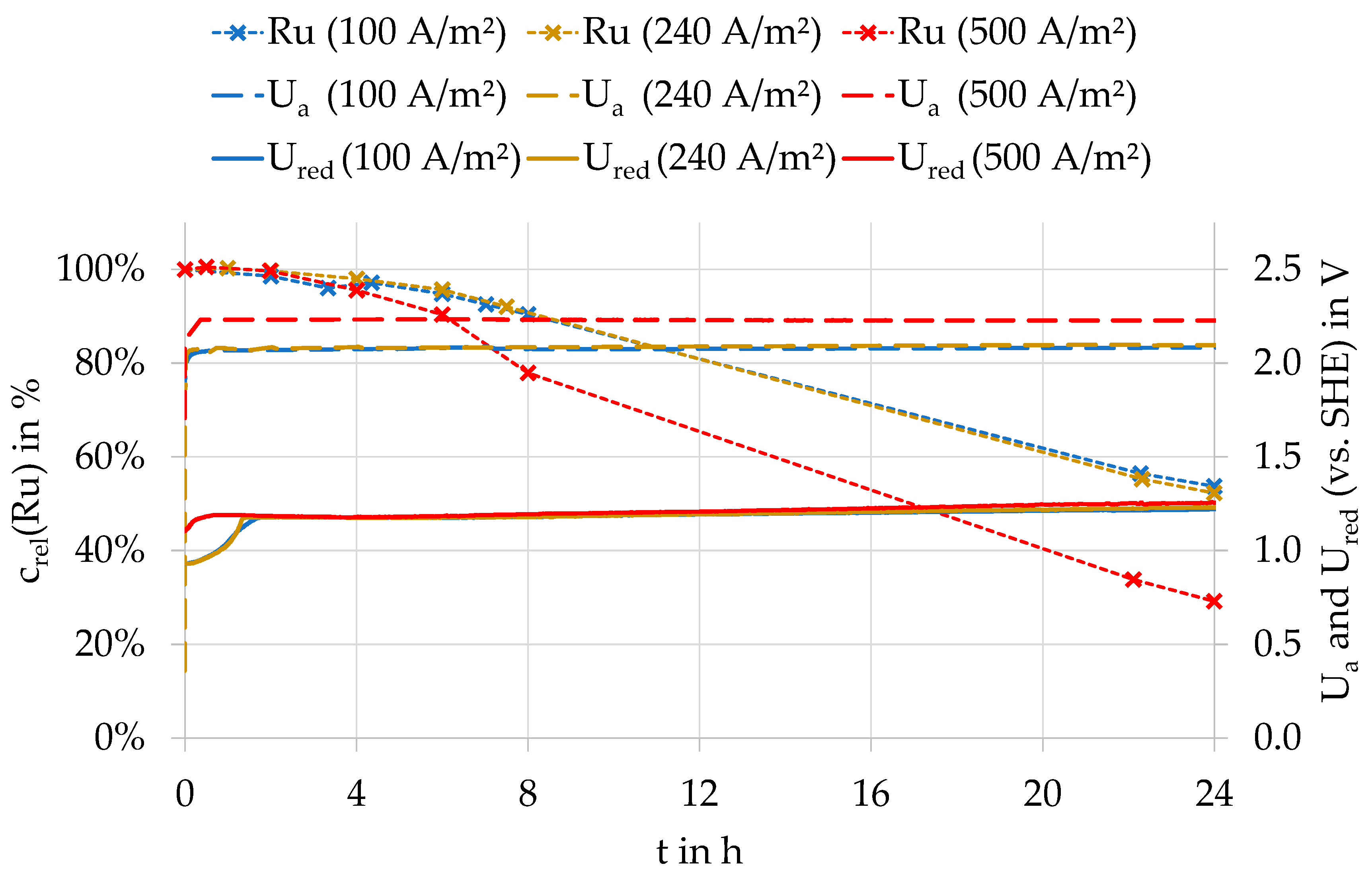
Figure 4.
Relative ruthenium concentration (crel(Ru)), anodic potential (Ua), and redox potential (Ured) at different temperatures during an electrolysis with a PbSnCa anode at 40 °C.
Figure 4.
Relative ruthenium concentration (crel(Ru)), anodic potential (Ua), and redox potential (Ured) at different temperatures during an electrolysis with a PbSnCa anode at 40 °C.
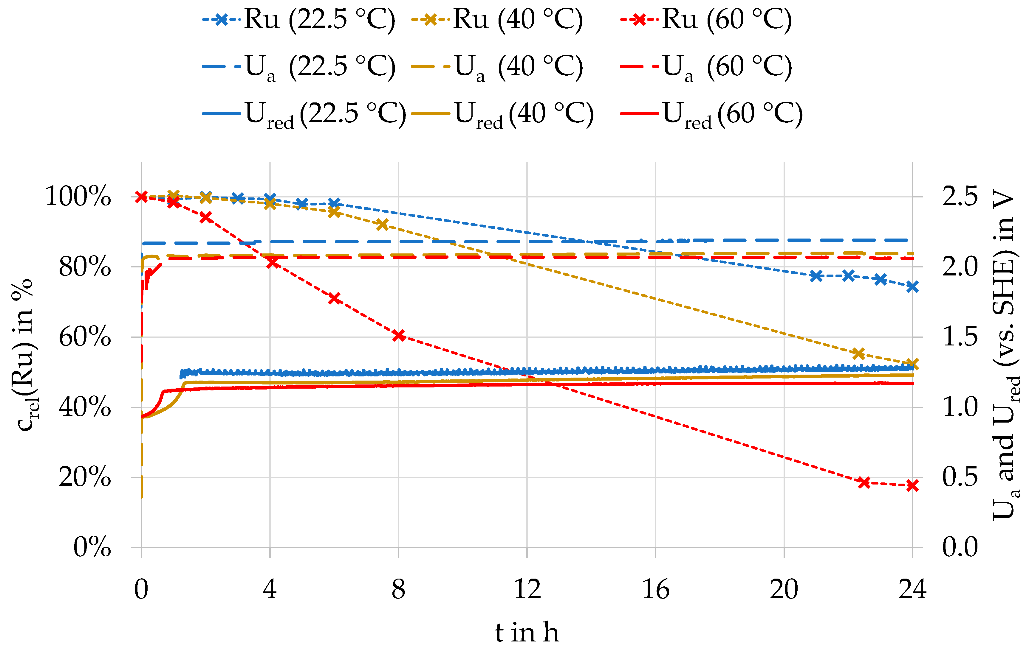
Figure 5.
Progress of relative ruthenium concentrations (crel(Ru)) at different anode potentials (Ua) during electrolysis at 240 A/m² and 60 °C.
Figure 5.
Progress of relative ruthenium concentrations (crel(Ru)) at different anode potentials (Ua) during electrolysis at 240 A/m² and 60 °C.

Figure 6.
Oxidation rate of ruthenium (v(Ru)Ox) as a function of anodic potential (Ua) and electrolyte temperatures; Δj—variation of the current density with different anode materials at 40 °C.
Figure 6.
Oxidation rate of ruthenium (v(Ru)Ox) as a function of anodic potential (Ua) and electrolyte temperatures; Δj—variation of the current density with different anode materials at 40 °C.
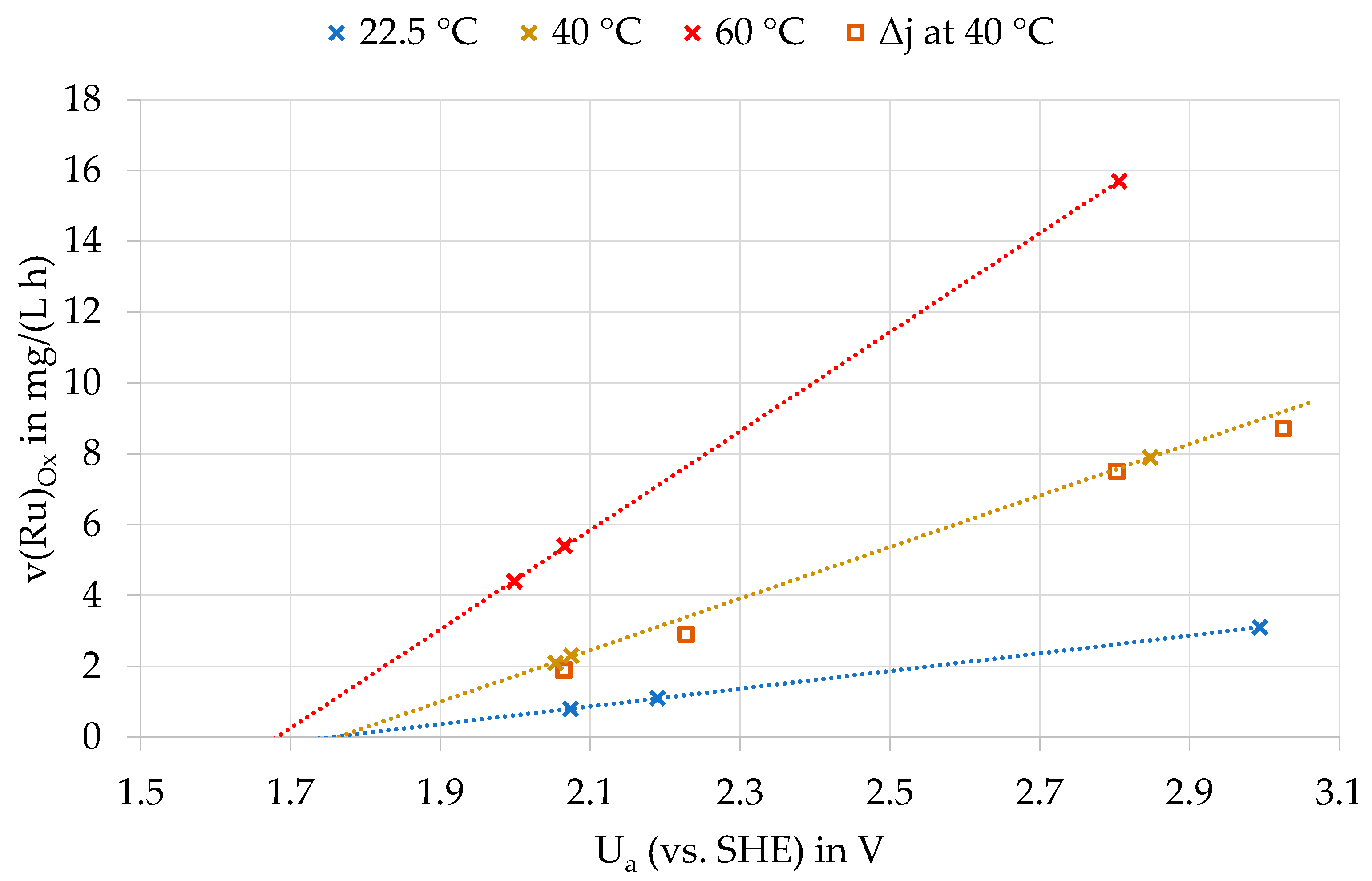
Figure 7.
Progression of the concentration of anodically formed oxidants (c(ox)) (one-electron-transition assumed), depending on the current density during electrowinning with a diamond anode at 40 °C.
Figure 7.
Progression of the concentration of anodically formed oxidants (c(ox)) (one-electron-transition assumed), depending on the current density during electrowinning with a diamond anode at 40 °C.

Figure 8.
Progression of the concentration of anodically formed oxidants (c(ox)) (one-electron-transition assumed), depending on the temperature during electrowinning with a diamond anode at 40 °C.
Figure 8.
Progression of the concentration of anodically formed oxidants (c(ox)) (one-electron-transition assumed), depending on the temperature during electrowinning with a diamond anode at 40 °C.

Figure 9.
Dependence of the oxidized ruthenium quantity (n(Ru)reacted) on the oxidizing agent addition (n(Ox)added).
Figure 9.
Dependence of the oxidized ruthenium quantity (n(Ru)reacted) on the oxidizing agent addition (n(Ox)added).


Table 1.
Standard electrode potentials of selected compounds in sulfuric acid electrolytes (data from [12]).
Table 1.
Standard electrode potentials of selected compounds in sulfuric acid electrolytes (data from [12]).
| Name | Chemical Formula | E0 in V | |||
|---|---|---|---|---|---|
| hydroxyl radical | 2.8 | ||||
| sulfate radical | 2.6 | ||||
| atomic oxygen | 2.42 | ||||
| ozone | 2.08 | ||||
| peroxodisulfate ion | 2.01 | ||||
| hydrogen peroxide | 1.76 | ||||
| chlorous acid | 1.57 | ||||
| chlorine dioxide | 1.50 | ||||
| hypochlorite ion | 1.49 | ||||
| chlorate ion | 1.45 | ||||
| peroxymonosulfate ion | 1.44 | ||||
| perchlorate ion | 1.38 | ||||
| chlorine | 1.36 | ||||
| oxygen | 1.23 | ||||
Publisher’s Note: MDPI stays neutral with regard to jurisdictional claims in published maps and institutional affiliations. |
© 2022 by the authors. Licensee MDPI, Basel, Switzerland. This article is an open access article distributed under the terms and conditions of the Creative Commons Attribution (CC BY) license (https://creativecommons.org/licenses/by/4.0/).
Share and Cite
MDPI and ACS Style
Thiere, A.; Bombach, H.; Stelter, M. The Behavior of Ruthenium in Copper Electrowinning. Metals 2022, 12, 1260. https://doi.org/10.3390/met12081260
AMA Style
Thiere A, Bombach H, Stelter M. The Behavior of Ruthenium in Copper Electrowinning. Metals. 2022; 12(8):1260. https://doi.org/10.3390/met12081260
Chicago/Turabian StyleThiere, Alexandra, Hartmut Bombach, and Michael Stelter. 2022. "The Behavior of Ruthenium in Copper Electrowinning" Metals 12, no. 8: 1260. https://doi.org/10.3390/met12081260
Note that from the first issue of 2016, this journal uses article numbers instead of page numbers. See further details here.