Article

Static Strength of Tubular K-Joints Reinforced with Outer Plates under Axial Loads at Ambient and Fire Conditions

Department of Civil Engineering, Faculty of Engineering, University of Guilan, Rasht 4199613776, Iran
*
Author to whom correspondence should be addressed.
Metals 2023, 13(11), 1857; https://doi.org/10.3390/met13111857
Submission received: 7 October 2023 / Revised: 29 October 2023 / Accepted: 5 November 2023 / Published: 6 November 2023
(This article belongs to the Special Issue Failure and Degradation of Metals)

Abstract

:
In this paper, the effect of the outer reinforcing plate on the initial stiffness, ultimate strength, and failure mechanisms of tubular K-joints under axial load at ambient and different fire conditions is evaluated. In the first phase, a finite element (FE) model was generated and verified by 13 experimental tests. In the next step, 1057 numerical models were generated. In these models, the welds joining the chord and braces were modeled. Using the produced FE models, the structural behavior under ambient and different elevated temperatures (20, 150, 300, 450, 600, 750, and 900 °C) was evaluated. The results showed that the outer plate can enhance the ultimate strength by up to 319% under fire conditions. Despite the considerable effect of the outer plate on the stiffness, ultimate strength, failure modes, and the frequent usage of the K-joints in tubular structures, the static response of the reinforced K-joints at ambient and elevated temperatures has not been studied. Hence, according to the extensive parametric studies, a highly precise practical design equation has been proposed based on the yield volume model for determining the ultimate strength.

1. Introduction

Jacket structures are commonly utilized in offshore engineering as a foundation for oil/gas platforms or wind turbines. The structures are primarily composed of steel tubular members, which are joined through welding to create tubular joints [1]. Tubular K-joints are one of the most commonly used types of tubular joints in steel structures. However, when exposed to fire, the performance of these joints can be compromised, resulting in catastrophic failure. The use of an outer plate reinforcement has been proposed as a potential solution to enhance the static strength of tubular K-joints (Figure 1). The plate can be used during both design and service. But there is no available study or equation on the strength of reinforced K-joints. Therefore, detailed guidelines on the behavior of K-joints with the outer plate at ambient and fire conditions are essential.
This article aims to investigate and analyze the effect of the stiffener and joint geometry on the strength of K-joints at room and different fire conditions. Compared to simple tubular joints such as T/Y-joints, K-joints are more generally applied in construction because two brace members in a K-joint are mainly under balanced axial loads which can considerably decrease the high stress concentration around the brace/chord intersection [2]. The results of this study can provide valuable insights into the design and optimization of fire-resistant steel structures.
In this study, in the first step, the numerical model is introduced. After that, the model is validated by 13 experimental tests. In the next step, 1057 FE models are generated and analyzed (Figure 1). The balanced axial load was applied. Also, no load or moment was applied on the chord ends. Also, the brace can only move in the brace axial direction. The 1057 FE models include seven different temperatures Tθ (Tθ = 20, 150, 300, 450, 600, 700, and 900 °C), three different λ (λ = 1, 2, and 3), three different η (η = 1, 2, and 3), seven different γ (γ = 10, 12, 15, 18, 20, 25, and 32), seven different β (β = 0.2, 0.3, 0.4, 0.5, 0.7, 0.8, and 0.9), five different τ (τ = 0.4, 0.5, 0.6, 0.7, 0.8, 0.9, and 1.0), five different ξ (ξ = 0.2, 0.3, 0.4, 0.5, and 0.6), and three different θ (θ = 30°, 40°, 45°, 50°, 60°). In addition, the material of the welds is considered the material of the brace member. The analysis results are utilized to show the effect of the different temperatures, the stiffener (λ and η), and the connection (θ, γ, β, τ, and ξ) on the stiffness, strength, and failure mechanisms. Based on the results of the K-joint FE models, validated using experimental data, an ultimate strength database was produced. In the final step, a practical formula with high accuracy is proposed, according to the yield volume model, to calculate the ultimate strength of the tubular K-joint with the outer plates at ambient and different fire conditions. The applicability of the derived formula is verified based on the experimental data.

2. Literature Review

This section reviews the relevant research works on the static behavior of tubular K-joints reinforced with the outer plate at ambient and fire conditions.

2.1. Tubular Joints Reinforced with the Outer Plate

Li et al. [3] conducted two experimental X-joints with outer plates under compression. Also, they numerically evaluated the effect of the stiffener geometry on the ultimate strength. They suggested using the outer plates with an equal width and length. Also, Ding et al. [4] experimentally showed that the plate can considerably increase the strength of the X-joint under tensile load. Zhu et al. [5] showed that the outer plate can remarkably increase the strength of T-joints subjected to compression. Nassiraei and Yara [6] evaluated the fLJF in K-joints with the outer plate. They observed that the plate can significantly decrease the fLJF.

2.2. Joints Reinforced with Other Methods

A few other methods are available for retrofitting tubular joints, such as internal ring [7], fiber-reinforced polymer (FRP) [8], doubler plate [9], joint can [10], concrete [11], collar plates [12,13], external ring [14], and other stiffeners [15].

2.3. K-Joints under Fire Conditions

He et al. [2,16,17] experimentally and numerically investigated the behavior of tubular K-joints under fire conditions. They showed that the critical temperature of a K-joint is slightly enhanced with the increase in β and θ. However, with the increase in γ, the critical temperature decreases slightly.
Ozyurt et al. [18] and Ozyurt and Wang [19] numerically evaluated K-joints at elevated temperatures. They showed that for the K-joints under axial load under fire conditions, the reduction in the joint strength at increasing temperatures more closely follows the reduction in the elastic modulus of steel at elevated temperatures. Xu et al. [20] provide a reference value for the design, maintenance, and reinforcement against stainless-steel K-joints. Shao et al. [21], by modeling 57 K-joints, proposed a design method for predicting the static strength of a Circular Hollow Section (CHS) unreinforced tubular K-joint at elevated temperatures. Chen et al. [22] studied K-joints under fire conditions. They showed that the failure mode of the axially loaded CHS joints under fire is chord plasticization. Lan et al. [23] studied the static strength of stainless-steel K- and N-joints at elevated temperatures. A unified strength equation for CHS K-joints at elevated temperatures was proposed by adopting the reduction factor of the yield stress. Bharti and Kumaraswamid [24] proposed a novel optimization method for bonded tubular gap K-joints made of FRP composites.
The ultimate strength of tubular joints under compressive load under fire conditions was experimentally evaluated by Tan et al. [25]. Their work included joints at 550 and 700 °C. Azari-Dodaran et al. [26,27] evaluated the strength of unreinforced K-joints at 200, 400, 500, and 700 °C. They proposed, via nonlinear regression analyses, a formula for determining the strength.

2.4. Concluding Remarks

The review showed that there is no study on the strength and failure mechanisms of K-joints with the outer plate at ambient or fire conditions. Furthermore, no equation is available for determining the strength of this joint at normal or elevated temperatures. However, K-joints are generally found in tubular structures, and the outer plate reinforcing method has a considerable effect on the strength.

3. FE Modeling

The weld joining the braces to the chord was produced based on the American Welding Society (AWS) suggestions [28] (Figure 1). The dihedral angle ( ψ ) is an important issue in designing the weld profile. It is calculated by Equation (1).
ψ = θ h e e l π θ     t o e π arccos θ s a d d l e π / 2 c r o w n
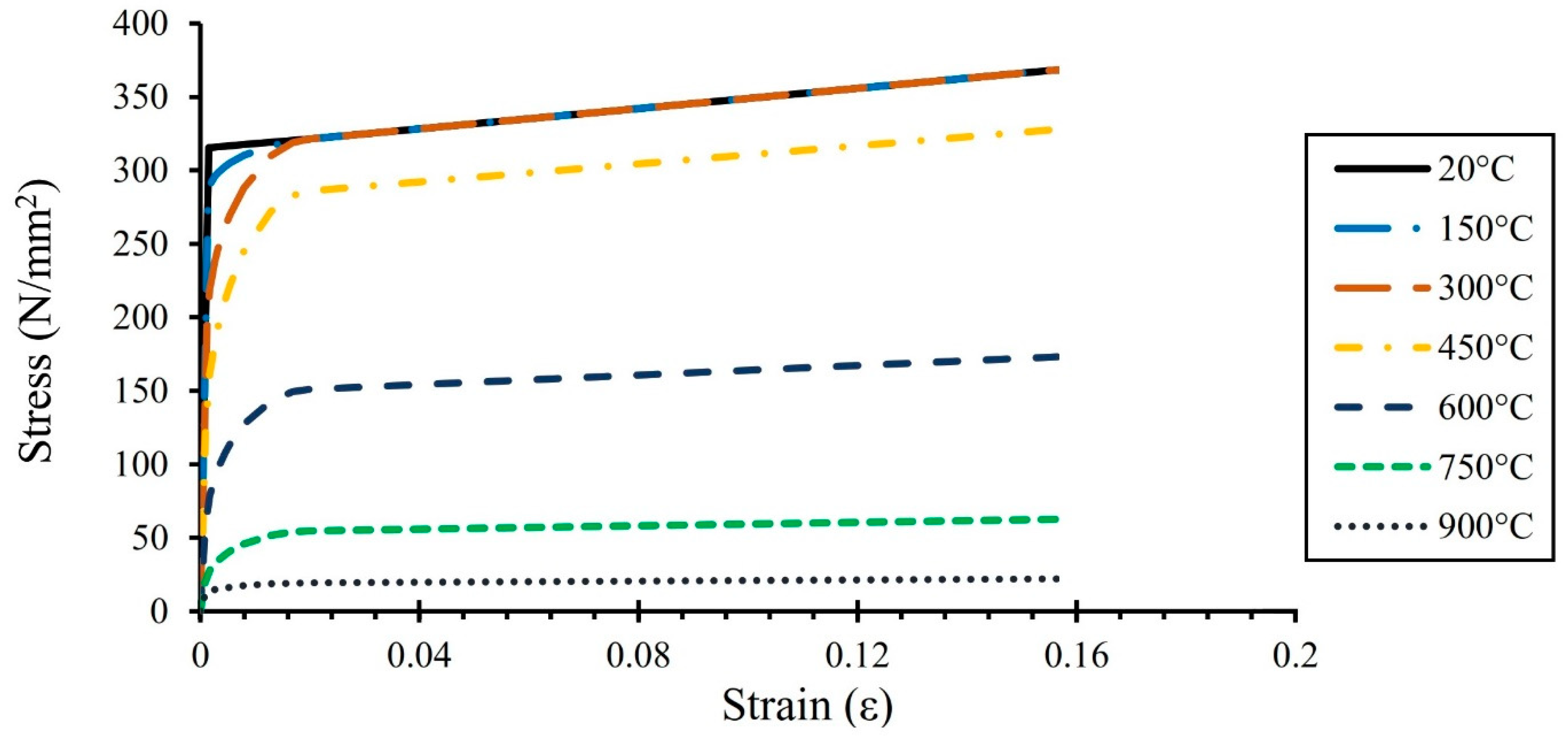
The isotropic hardening plasticity model and Mise’s failure yield standard were applied. For defining the material of the members (chord, braces, weld, and plate) under fire conditions, the recommendations of EN 1993-1-2 [29] are utilized. They are shown in Figure 2. Also, the stress–strain diagrams are converted to true stress–strain diagrams, as shown in Equations (2) and (3). The yield strength and Young’s modulus at ambient temperatures are 315 × 106 Pa and 205 × 109 Pa, respectively. Also, Poisson’s ratio is 0.3.
εT = ln (1 + ε)
σT = σ (1 + ε)
The engineering and true strains are represented by ε and εT, respectively, while the engineering and true stresses are represented by σ and σT.
In the present study, ANSYS element type SOLID186 was utilized to model the chord, brace, plate, and weld profile. The SOLID186 element is defined by 20 nodes with three degrees of freedom per node. In order to guarantee the mesh quality, a sub-zone mesh generation method was used during the FE modeling. In this method, the entire structure is divided into several different zones according to the computational requirements. The mesh of each zone is generated separately using different densities and then, the mesh of the complete model is produced by merging the meshes of all the sub-zones. This technique can easily control the mesh quantity and quality and avoid badly distorted elements. To validate the convergence of the FE results, a convergence test with different mesh densities was performed before generating the generated FE models for the parametric study. Figure 3 shows the meshed joint reinforced with the outer plate.
The brace ends were subjected to a balanced axial load, whereas the displacement of the chord ends was restrained. To expedite calculations, only one-fourth of the entire unreinforced and plate-reinforced K-joints were modeled.
The steady-state analysis was used to determine the ultimate strength under fire conditions. Nonlinear static analysis considered both material and geometric nonlinearities.
The arc-length method is suitable for nonlinear static equilibrium solutions of unstable problems. Applications of the arc-length method involve the tracing of a complex path in the load-displacement response into the buckling/post-buckling regimes. The arc-length method uses the explicit spherical iterations to maintain the orthogonally between the arc-length radius and orthogonal directions. It is assumed that all load magnitudes are controlled by a single scalar parameter (i.e., the total load factor). An unsmooth or discontinuous load-displacement response in the cases often seen in contact analyses and elastic-perfectly plastic analyses cannot be traced effectively by the arc-length solution method. Mathematically, the arc-length method can be viewed as the trace of a single equilibrium curve in a space spanned by the nodal displacement variables and the total load factor. Due to this reason, all options of the Newton–Raphson method (an iterative process of solving nonlinear equations) were used as the basic method for the arc-length solution. As the displacement vectors and the scalar load factor are treated as unknowns, the arc-length method itself is an automatic load step method. During the solution, the arc-length method will vary the arc-length radius at each arc-length sub-step according to the degree of nonlinearities that is involved.
Van der Vegte et al. [30] defined a method for determining the ultimate strength, which specified a deformation limit of 6%D relative to the chord bottom (D is chord diameter). When the joint exhibited a distinct peak before reaching the deformation limit, the load at the peak point is taken as the connection strength.

4. Validation and Parametric Study

4.1. Validation of the FE Model

The FE program ANSYS is used for the numerical simulations. To the best of the authors’ knowledge, there is no experimental, numerical, or practical data available on the initial stiffness, ultimate strength, and failure modes of K-joints with the outer plate at normal or high temperatures. Hence, the following experimental data were used: two unreinforced K-joints under axial load (S1 and S2), two unreinforced X-joints under axial load (S3 and S4), two tubular X-joints reinforced with the outer plate under compressive load (S5 and S6), two X-joints with the outer plate under tensile load (S7 and S8), two tubular T-joints with the outer plate under axial load (S9 and S10), and three unreinforced T-joints under axial load under different fire conditions (S11–S13). Table 1 and Table 2 tabulated the geometrical and material properties used for the simulation of the specimens (S1–S13). The numerical models were carried out and analyzed in ANSYS with the same geometry as the test specimens to give a contrast and supplement the experimental study.
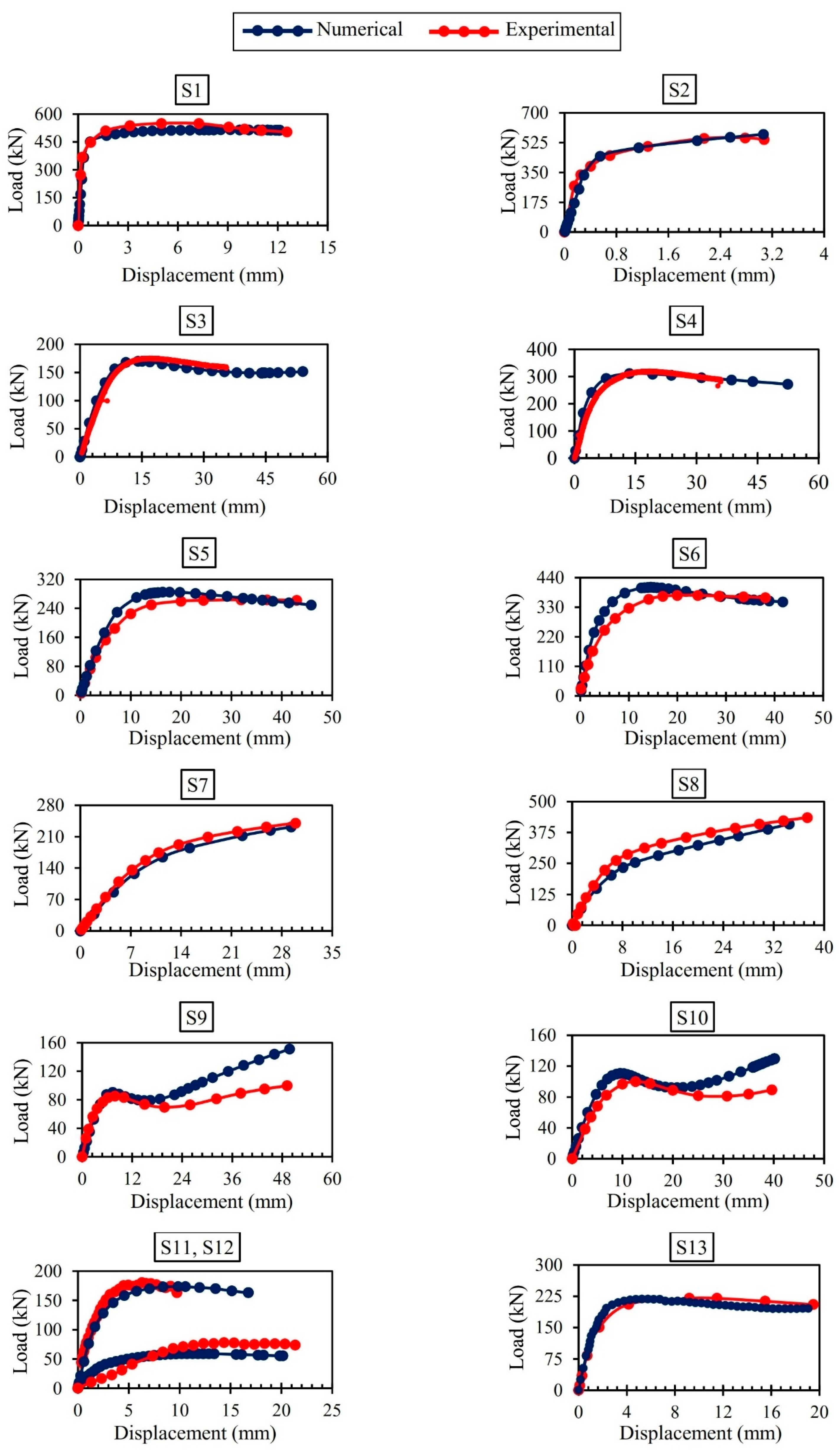
The load-displacement curves of the experimental and corresponding numerical tests are shown in Figure 4. It should be noted that all 13 joints are under axial load. From curves S1–S13, it can be seen that the present FE model can accurately estimate the initial stiffness of the joints with the outer plate under axial load at ambient and high temperatures. Also, the comparison of the ultimate strength between the experimental and numerical tests is tabulated in Table 3. It indicates that the strength values obtained from the experimental and numerical tests are well close. Consequently, from Figure 4 and Table 3, it can be seen that the proposed FE model can well estimate the static response of the K-joints with and without the outer plates under axial load at ambient and different fire conditions.

4.2. Details of the Parametric Study

In total, 1057 K-joints with outer plates were generated to evaluate the effect of the high temperatures, geometrical parameters of the stiffener (λ and η), and joint geometry (ξ, β, γ, τ, and θ), on the initial stiffness, strength, and failure shapes of the K-joints under balanced axial loads. It should be noted that in the previous research works conducted on the tubular joints under fire conditions, a temperature higher than 800 °C is not investigated [7,12,18,25,26,27]. This is because the strength of steel tubular joints after this temperature is very decreased and small. The explanations are added in the parametric study. The definitions of the parameters are shown in Figure 1.

4.3. Efffect of the θ, Plate Size (λ, η), and High Temperatures

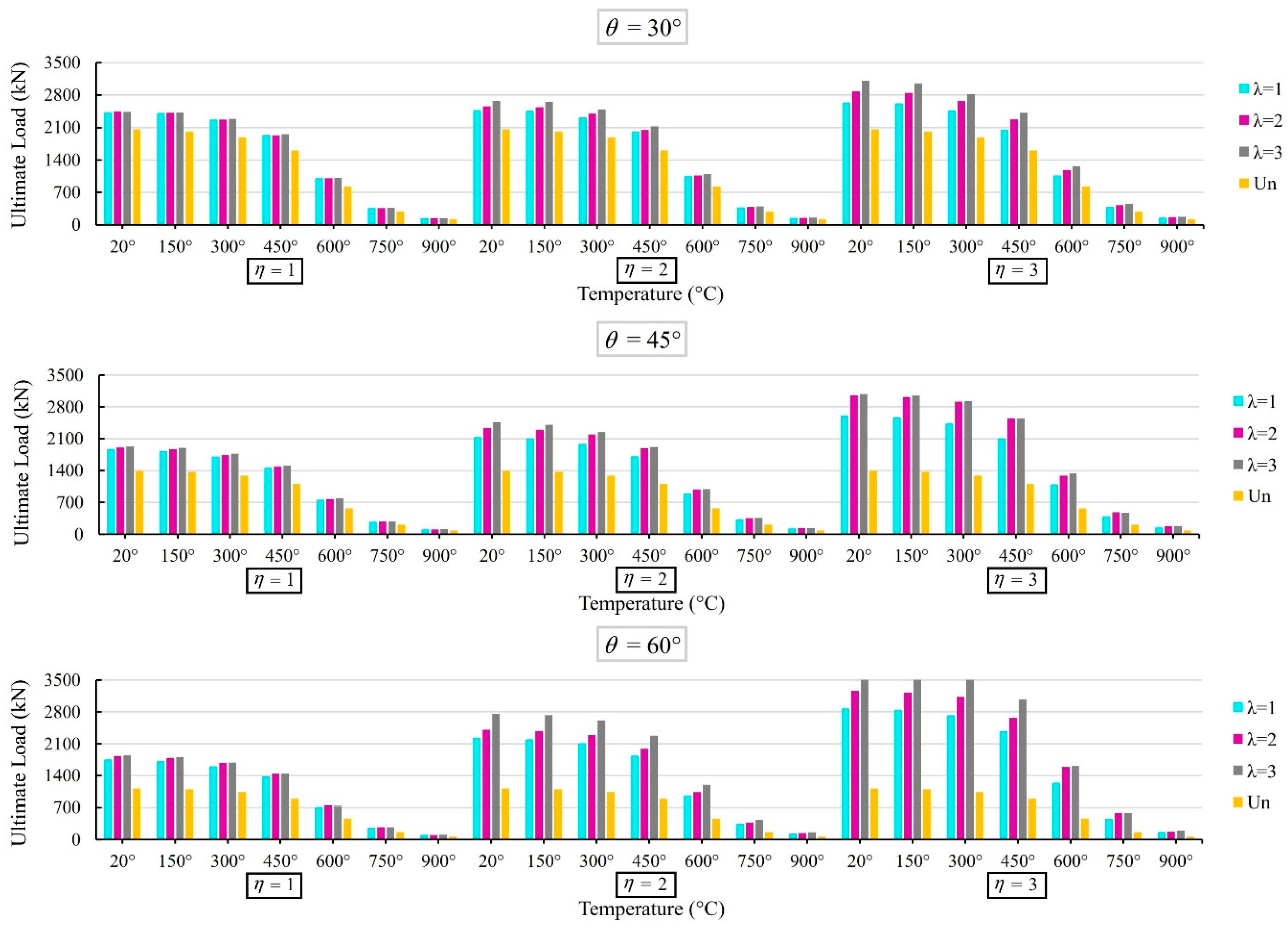
Figure 5 shows the load-displacement curves of the joints with β = 0.7, γ = 18, τ = 0.8, ξ = 0.4, three θ values (θ = 30°, 45°, and 60°), three plate thickness factor values (λ = 1.0, 2.0, and 3.0), and three plate length factor values (η = 1, 2, and 3) at seven high temperatures. The results show that the increase in the temperature and brace angle lead to the decrease in the initial stiffness. Figure 6 shows that in the plate-reinforced K-joints under fire conditions, the ultimate strength remarkably increases with the increase in the thickness and length of the stiffener, similar to the research works conducted by Azari-Dodaran et al. [27] on the collar plate size in K-joints. This is because the use of a bigger plate can transfer the load on more areas of the chord member. Hence, more energy can be dissipated. For example, in the K-joints with β = 0.7, γ = 15, τ = 0.8, ξ = 0.4, θ = 60°, and η = 3 at 750 °C, the increase in the λ from 1 to 3 leads to the enhancement in the strength from 447.28 to 581.72 kN. Furthermore, it is interesting that the strength of the associated unreinforced joint is much smaller (it is equal to 164.92 kN). It can be seen that the plate can increase the strength by up to 253%. Also, the decrease in the brace angle leads to the increase in the strength of the K-joint at all elevated temperatures.
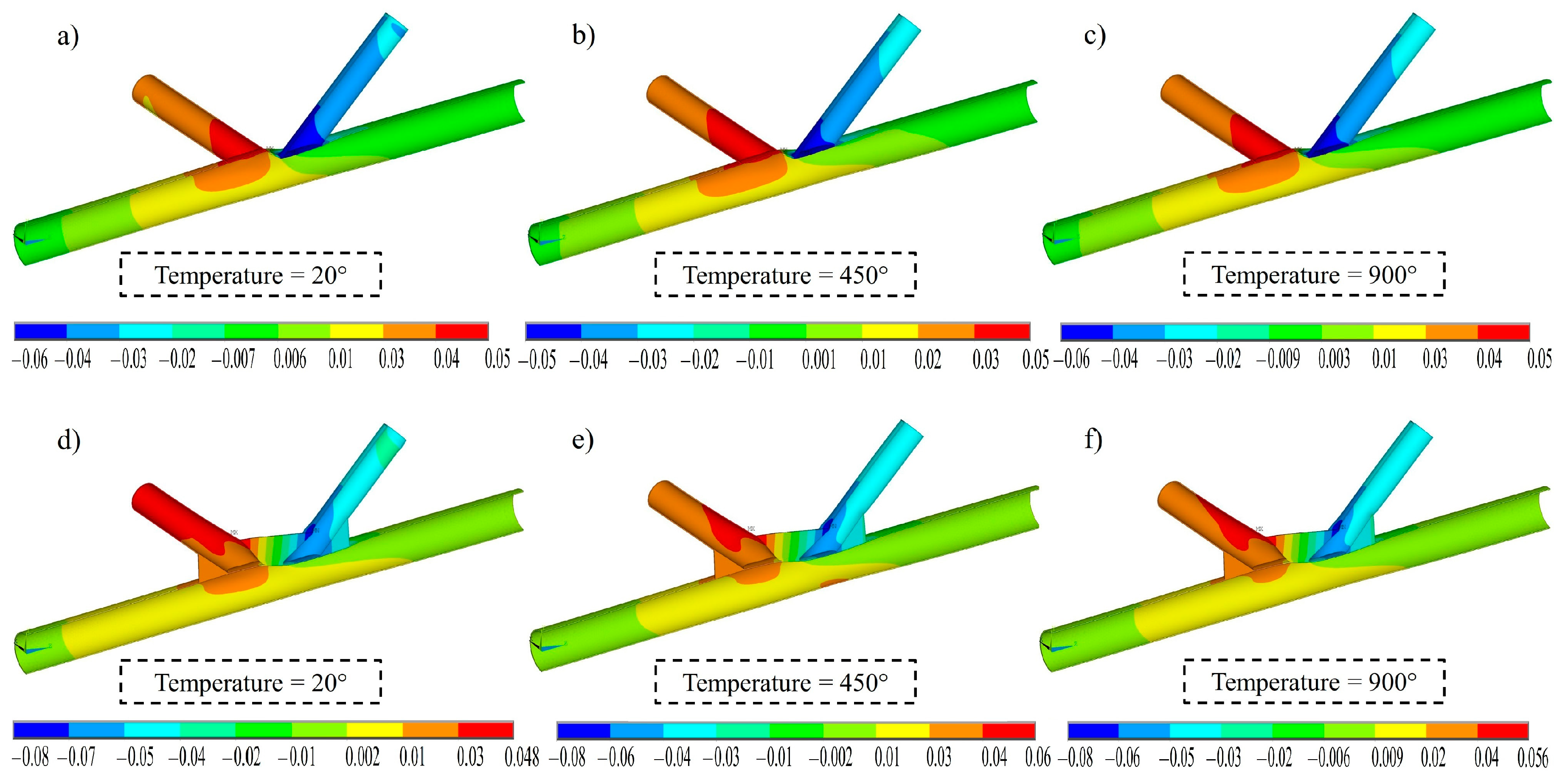
Figure 7 compares the deformed shapes of the unreinforced and reinforced K-joints at 20, 450, and 900 °C. All the joints are in the same applied displacement on the brace end. It can be seen that in the unreinforced joints, the deformations are local. They happen in the joint intersection. But, in the reinforced joints, the deformations are more global. The deformation happened in more regions of the chord wall. Hence, this phenomenon can dissipate more energy.

4.4. Effect of the γ, Plate Size (λ, η), and High Temperatures

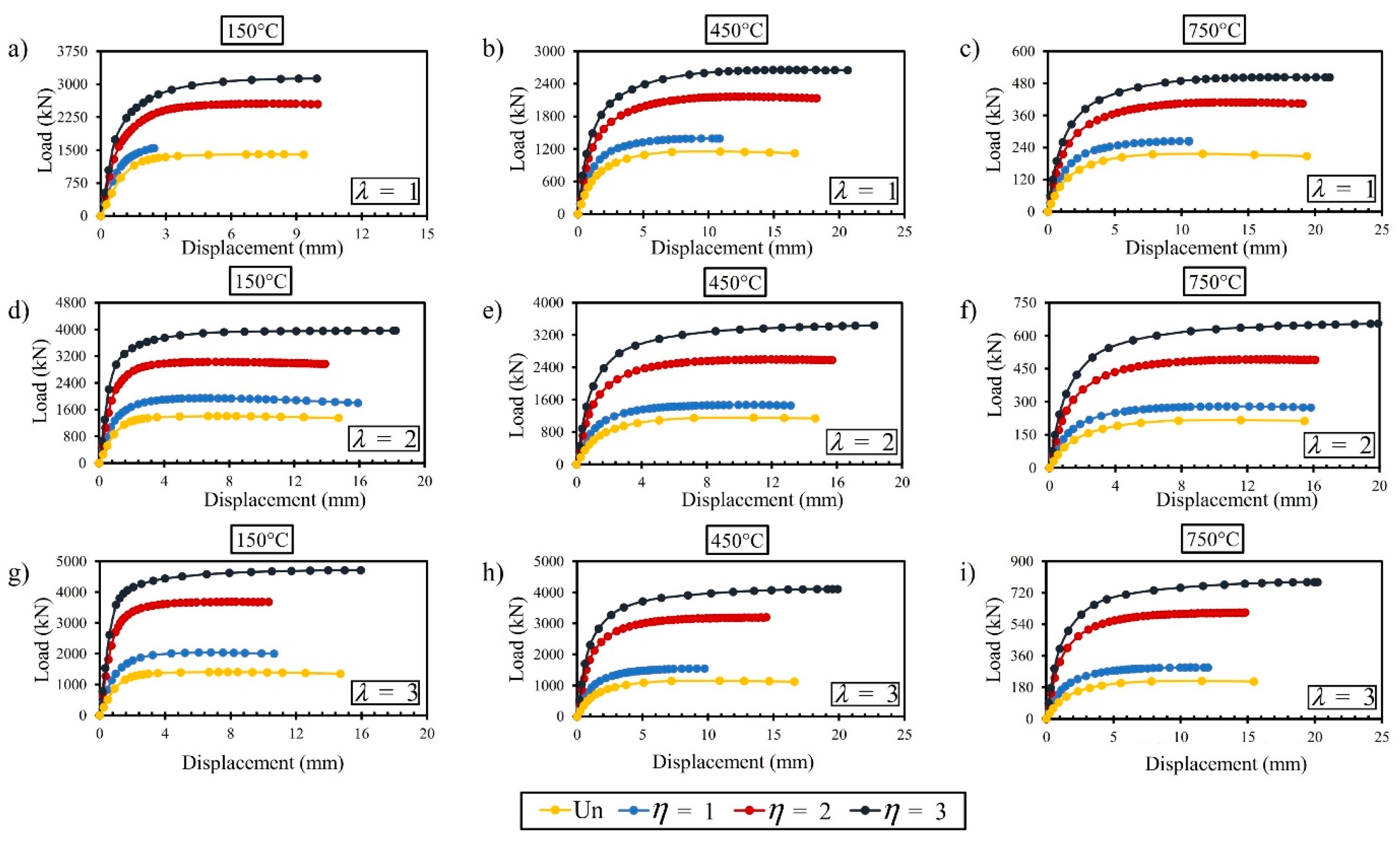
Nine charts are shown in Figure 8. They indicate the load-displacement curves of the reinforced joints with γ = 10 and different values of the plate length and thickness at three various temperatures (150, 450, and 750 °C). Figure 8 shows that the increase in the temperatures notably results in the decrease in the stiffness. This is because the mechanical properties of the steel material notably decrease due to the increase in the temperature. In addition, under all fire conditions, the decrease in the η results in the considerable decrease in the stiffness.
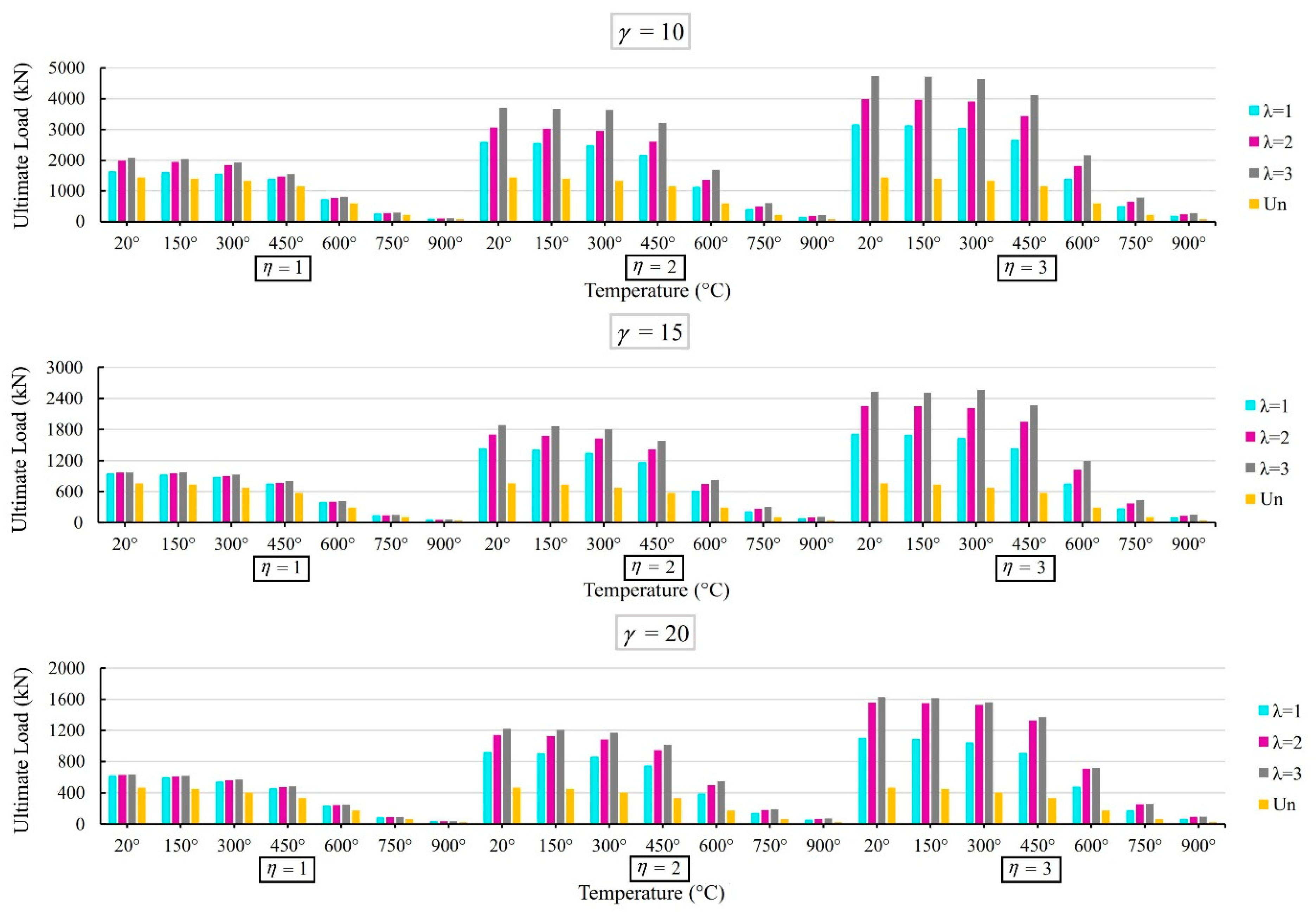
Figure 9 shows that at all high temperatures, the increase in the γ results in the decrease in the strength. This is because the plate thickness value has a linear ratio with the T. Consequently, the increase in the γ results in the decrease in the T and tp. The decrease in the two parameters leads to a considerable decrease in the connection stiffness. As a result, under all fire conditions, the joint strength decreases by increasing the γ. It should be noted that the same result was concluded on the effect of this parameter on the ultimate strength of K-joints with a collar plate under fire conditions [7]. Also, the results show that the strength of a K-shape joint with the plate can be up to 419% of the strength of the associated unreinforced joint. Also, the use of the bigger plate results in a greater enhancement in the strength. This is because in the reinforced connections, the plate enhances the chord wall thickness close to the connection intersection. Hence, the increase in the stiffening plate thickness results in the considerable increase in the strength in K-joints. Moreover, the use of a bigger η results in more propagation of the plastic zones (Figure 10). For joints with a big plate size, considerable deformations happen in the stiffener and the large area of the chord wall. Whereas for K-joints with a small stiffener, considerable deformations only happen in the stiffener and the small zone of the joint intersection. The increase in the plastic zone in the chord wall results in the increase in the static strength. In other words, the deformation in the reinforced K-type joint with a big stiffener is more uniform than the deformation in the associated joint with a small stiffener.

4.5. Effect of the β, Plate Size (λ and η), and High Temperatures

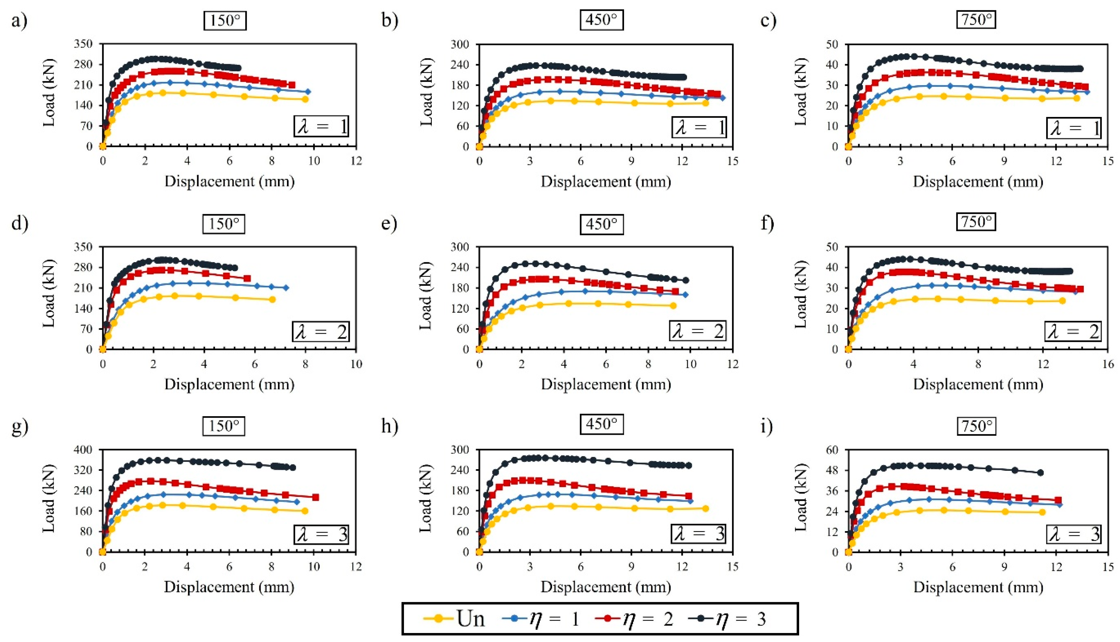
Figure 11 shows the load-displacement curves of the plate-reinforced joints with β = 0.2, γ = 32, τ = 0.5, ξ = 0.3, θ = 40°), various values of the stiffener size (λ and η), and different high temperatures. The comparison between Figure 11a–c shows that in the joints reinforced with a small stiffener thickness (λ = 1), the increase in the temperature results in the decrease in the stiffness. Also, the same result can be found, from Figure 11d–i, for the joints with an intermediate and big stiffener thickness (λ = 2 and 3). The increase in the temperatures leads to the decrease in the steel strength. The decrease in the steel strength leads to the decrease in the stiffness in the chord and plate. Moreover, the decrease in the stiffness is more considerable at temperatures of more than 400 °C, since the yield stress notably decreases at temperatures of more than 400 °C. The curves indicated that the increase in the plate length factor (η) results in the considerable enhancement in the initial stiffness under fire conditions. Also, from Figure 11a–i, it can be observed that under fire conditions, the use of the plate leads to the increase in the area under the load-displacement curves. Hence, the stiffener can significantly improve the ductility of the joints under fire conditions.
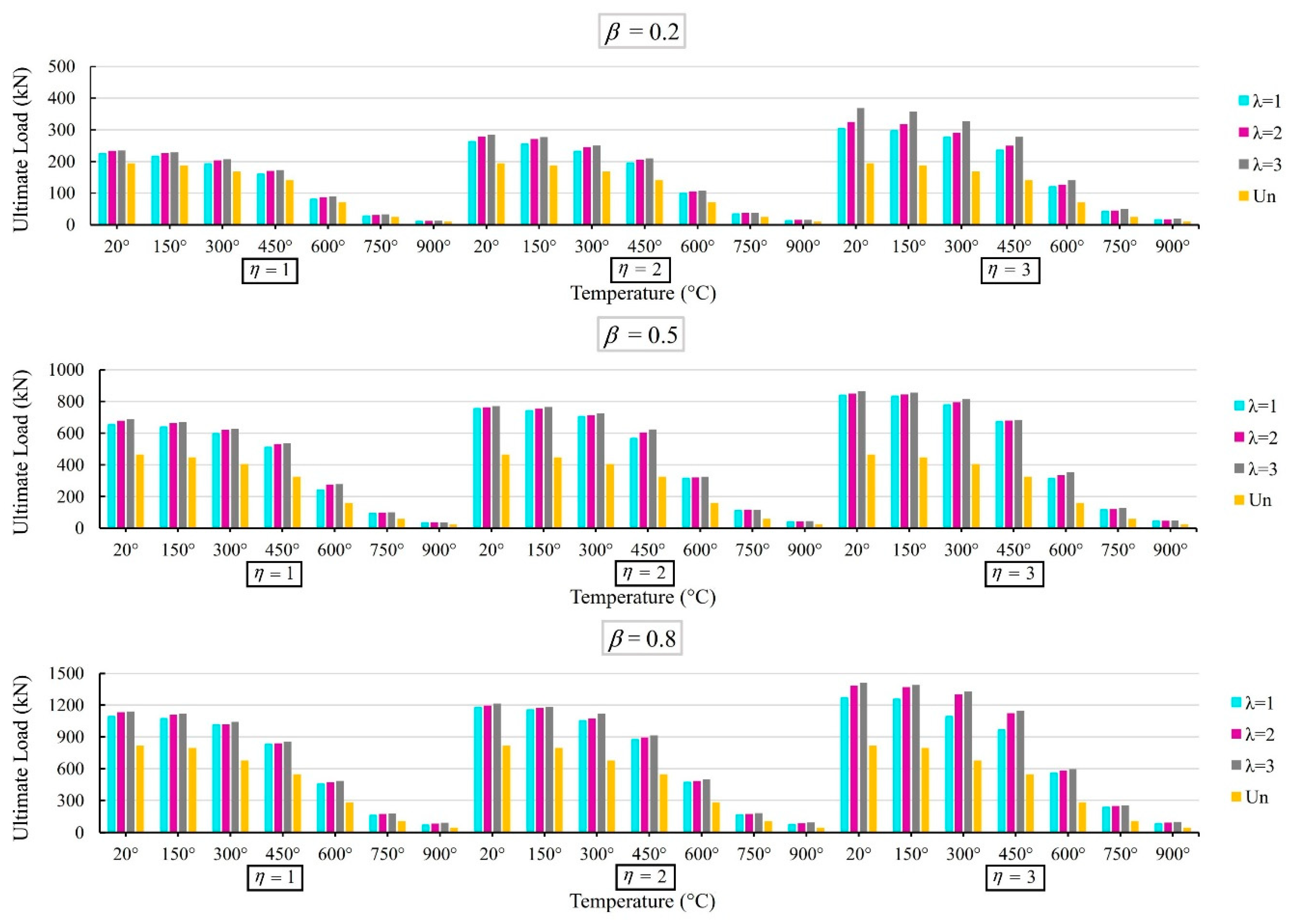
Figure 12 indicates that the increase in the β results in the noticeable enhancement in the strength (similar to the effect of the β on the T/Y-joints with a collar at elevated temperatures [12]). This is because the increase in the β leads to the increase in the brace diameter and plate length. Also, the ultimate strength of the joints with the plate is notably bigger than the corresponding unreinforced joint, at all high temperatures. Also, the results show that the decrease in the connection strength, because of the increase in the temperature, is more considerable at temperatures of more than 400 °C, since the strength of the joints is related to the yield stress (fy). As listed in Table 3.1. of Eurocode EN-1993-1-2 (2005), at temperatures of more than 400 °C, the yield stress (fy) of the members significantly decreases due to the increase in the temperature. Hence, the strength was notably decreased for temperatures of more than 400 °C.

4.6. Effect of the τ, Plate Size (λ and η), and High Temperatures

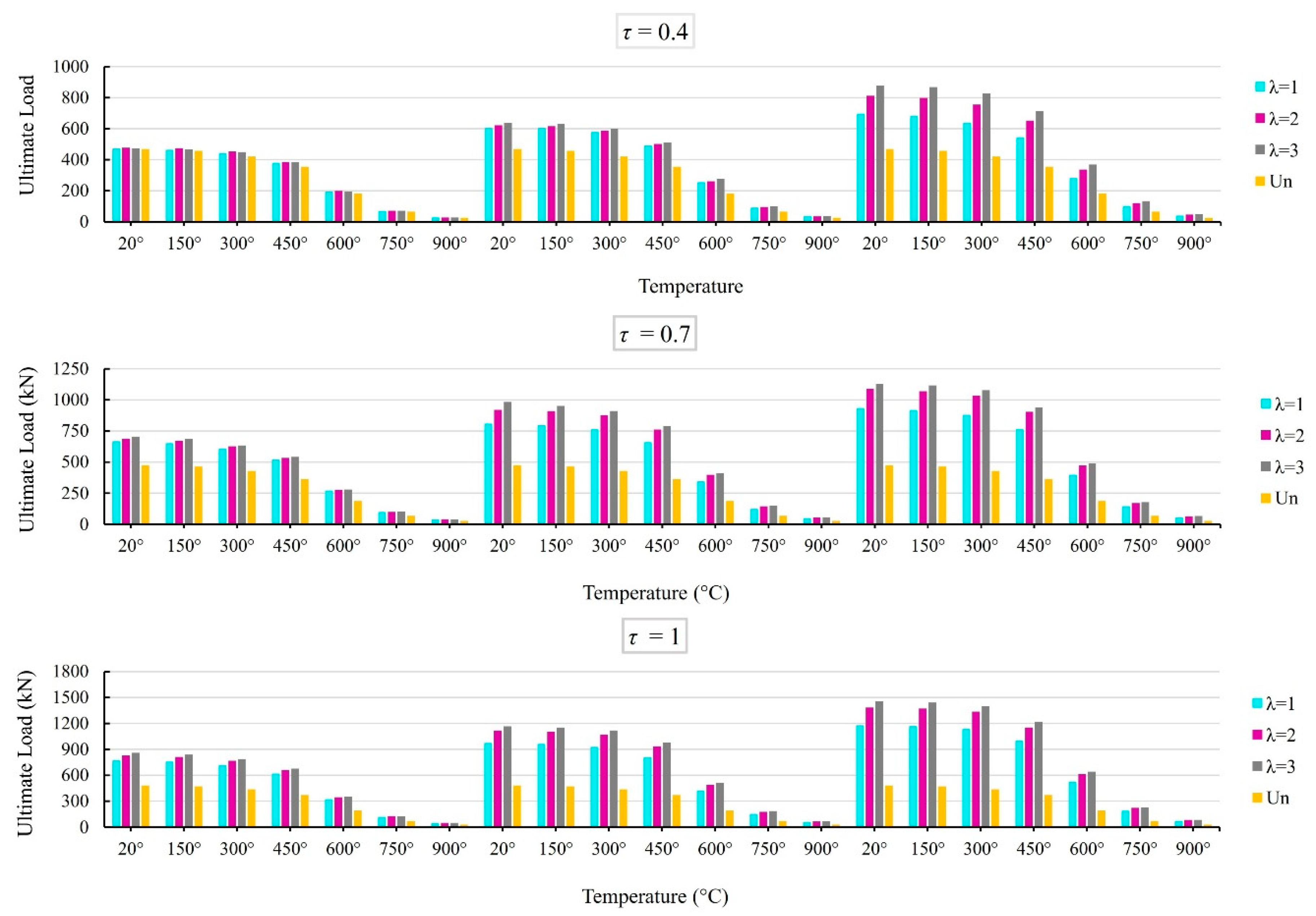
Figure 13 compares the ultimate strength of the reinforced joints with the ultimate strength of the corresponding unreinforced joint. The results are obtained for the joints with different τ (τ = 0.4, 0.7, and 1.0) at seven various temperatures. The results show that the increase in the τ results in the increase in the strength of the reinforced joints. Also, at all temperatures, the strength of the reinforced joint is notably higher than the strength of the associated unreinforced joint. Moreover, the increase in the plate size leads to a greater increase in the strength. Furthermore, the effect of the η and λ on the strength becomes more considerable when one of these parameters is big. For instance, in the reinforced joints with γ = 25, ξ = 0.2, β = 0.4, θ = 45°, and τ = 0.7, at 750 °C, when λ = 1, the increase in the η from 1 to 3 results in the increase in the strength from 97.28 to 143.25 kN. It means a 47% enhancement in the strength. On the other hand, in the same joints, when λ = 3, the increase in the η from 1 to 3 results in the increment of the strength from 100.55 to 176.90 kN. It shows a 76% enhancement in the strength. The results show that the strength of an X-type joint with the plate can be up to 312% of the strength of the associated unreinforced joints, respectively.

4.7. Effect of the ξ, Plate Size (λ and η), and High Temperatures

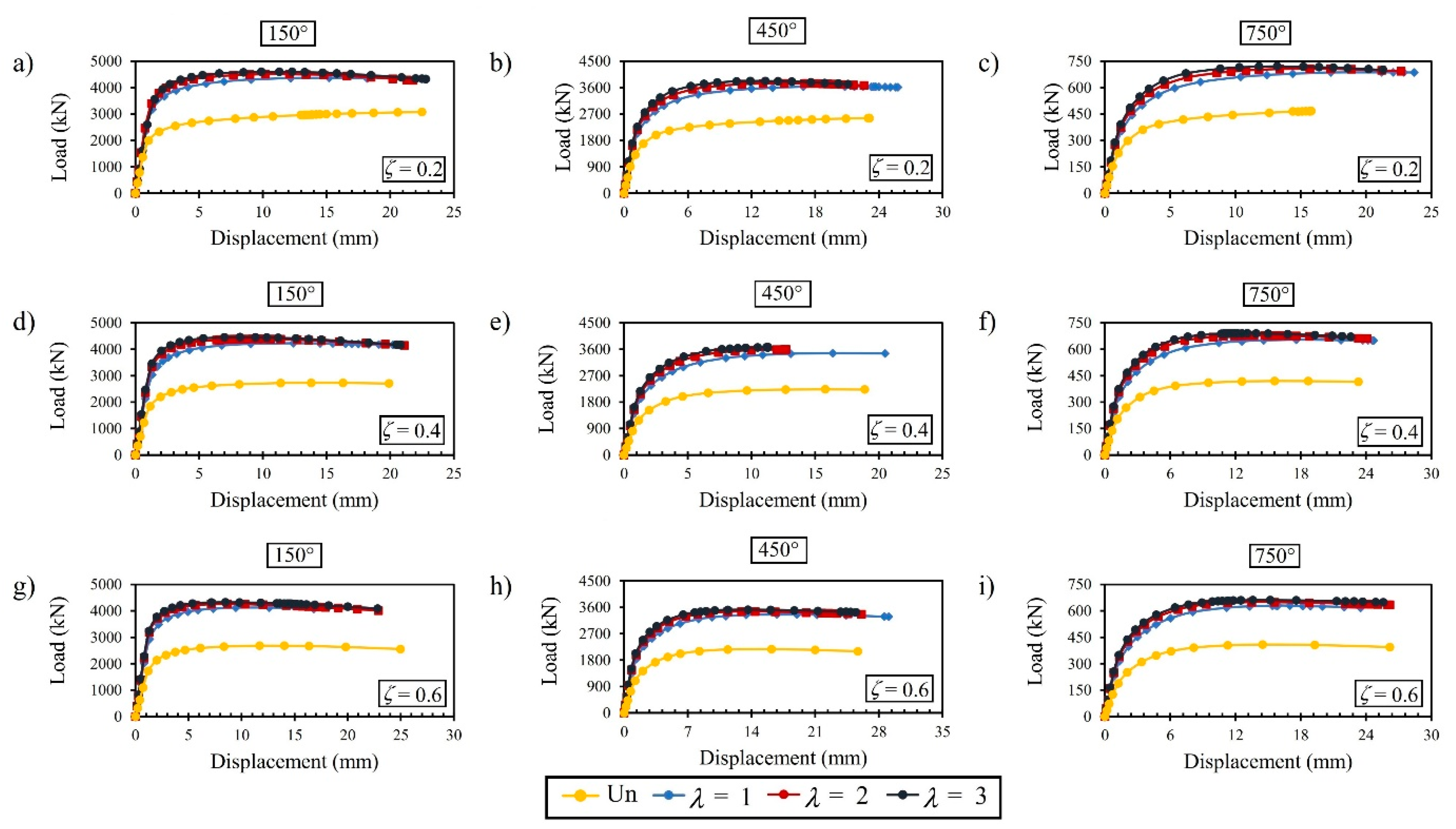
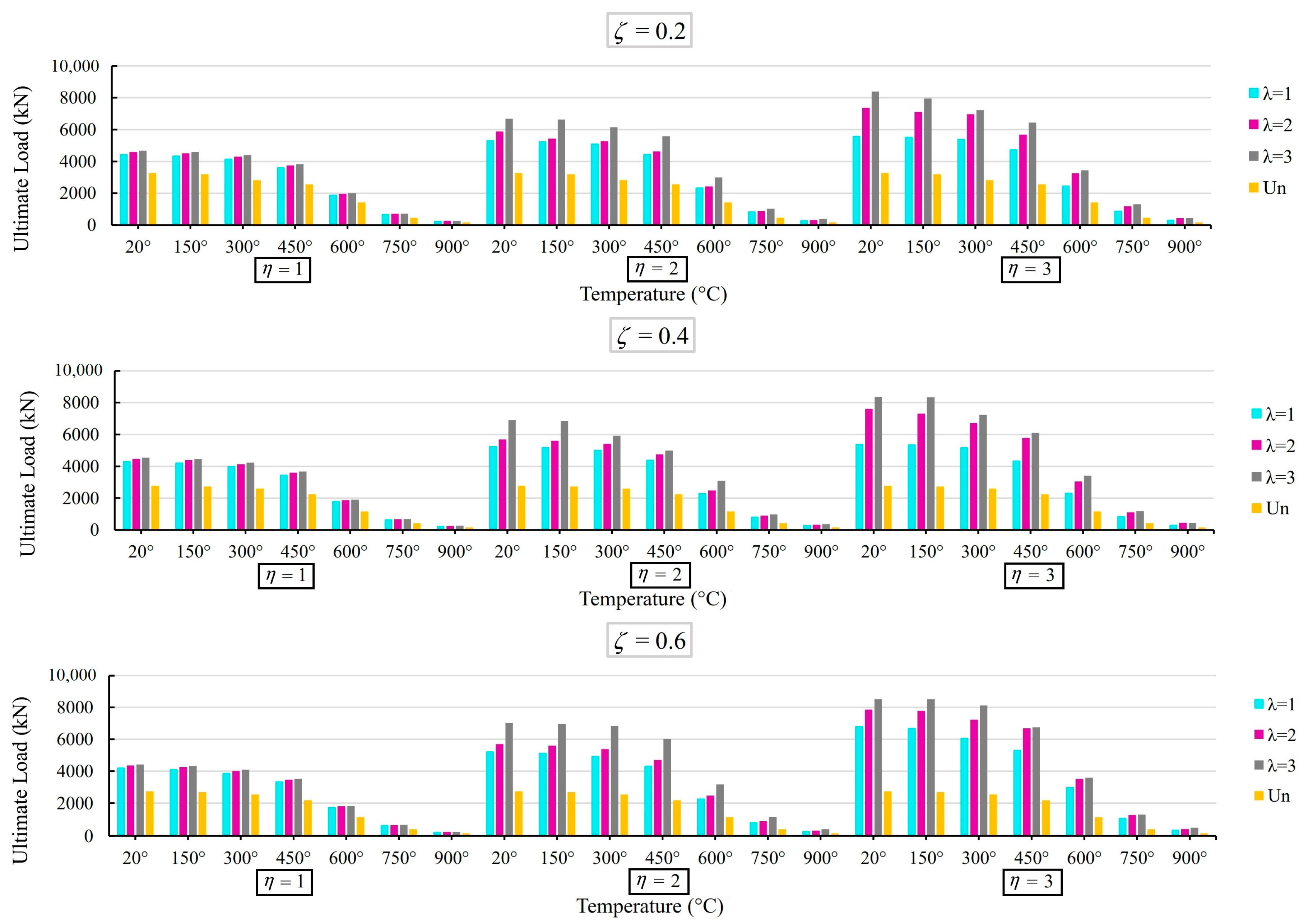
Figure 14 shows the static response of the unreinforced and reinforced joints with various gap factor values ξ (ξ = 0.2, 0.4, and 0.6) at 150, 450, and 750 °C. The results indicate that the effect of the ξ on the initial stiffness can be ignored. But, the difference between the curves of the unreinforced and corresponding reinforced joints is considerable. The plate, under fire conditions, can notably increase the stiffness and absorbed energy (the area of the under curve). Also, the increment in the temperatures leads to the decrease in the stiffness and absorbed energy. From Figure 15, it can be observed that the effect of the length and thickness of the plate on the strength becomes more considerable when one of these parameters is big. However, the effect of the ξ on the strength is slight.
Section 4.2, Section 4.3, Section 4.4, Section 4.5 and Section 4.6 prove the important role of the temperature, the stiffener geometry, and the connection geometry on static behavior, and take their relationship during the evaluation of K-joints under fire conditions.

5. The Practical Equation

Until now, no equation exists for determining the strength of the plate-reinforced K-joints at room and high temperatures. Consequently, in this paper, a practical parametric equation, via the yield volume theory, is established for this matter.
This study investigated nine variables associated with the ultimate strength increment proportion Rp for reinforced K-joints, including η, λ, θ, γ, τ, β, ξ, and Tθ (temperatures). The final stage of unreinforced joints indicated that only the intersecting body between the chord and brace (V1) yielded. However, both the intersecting body between the chord and brace (V1) and the volume of the entire plate (Vp) yielded joints reinforced with an outer plate. Figure 16 illustrates these findings.
P = π d 2 arcsin β β + sin θ
V 1 = 2 P . T . t
Arcsin β β + 1 6 β 3
V 1 = 2 P T t = π T t d arcsin β β + sin θ
V p l a t e = l s t s ( 2 l s + g + 2 d sin θ 2 d sin 2 θ )
R p = 1 + V p V 1 = 1 + 2 γ η λ ( 2 η β + ζ + 2 β sin θ 2 β sin 2 θ ) π τ 1 + β 2 6 + sin θ
Equation (9), by considering the temperature, can be shown as:
R p = 1 + C 1 K t e m p C 2 γ C 3 η C 4 λ C 5 [ C 6 η C 7 β C 8 + C 9 ζ C 10 + C 11 β C 12 sin C 13 θ ] C 14 τ C 15 C 16 + C 17 β C 18 + C 19 sin C 20 θ
The coefficients ( C 1 C 20 ) can be obtained via nonlinear regression analyses. The data used in the regression analyses contain the amounts of the dependent parameter (i.e., Rp) and independent parameters (η, λ, θ, γ, τ, β, ξ, and Tθ). It concluded as being −347 for C 1 , 0.035 for C 2 , 0.4 for C 3 , 1.19 for C 4 , 0.4 for C 5 , −37 for C 6 , −0.9 for C 7 , 7 for C 8 , −76.1 for C 9 , 0.16 for C 10 , 29 for C 11 , −0.13 for C 12 , −1 for C 13 , −116 for C 14 , −0.9 for C 15 , −237 for C 16 , −725 for C 17 , 2.2 for C 18 , 107 for C 19 , and 121 for C 20 . The formulation for the strength enhancement ratio of the external ring reinforcement method can be shown as:
R p = 1 + 347 K t e m p 0.035 γ 0.405 η 1.19 λ 0.4 [ 37 η 0.9 β 7 29 β 0.13 sin 1 θ + 76.1 ζ 0.16 ] 116 τ 0.9 725 β 2.2 107 sin 121 θ + 237 R 2 = 0.91
In Equation (11), Rp is the strength ratio of the external-plate-reinforced X-type connection to the corresponding unreinforced X-joint under fire conditions. The R2 value for the proposed formula is considered to be acceptable.
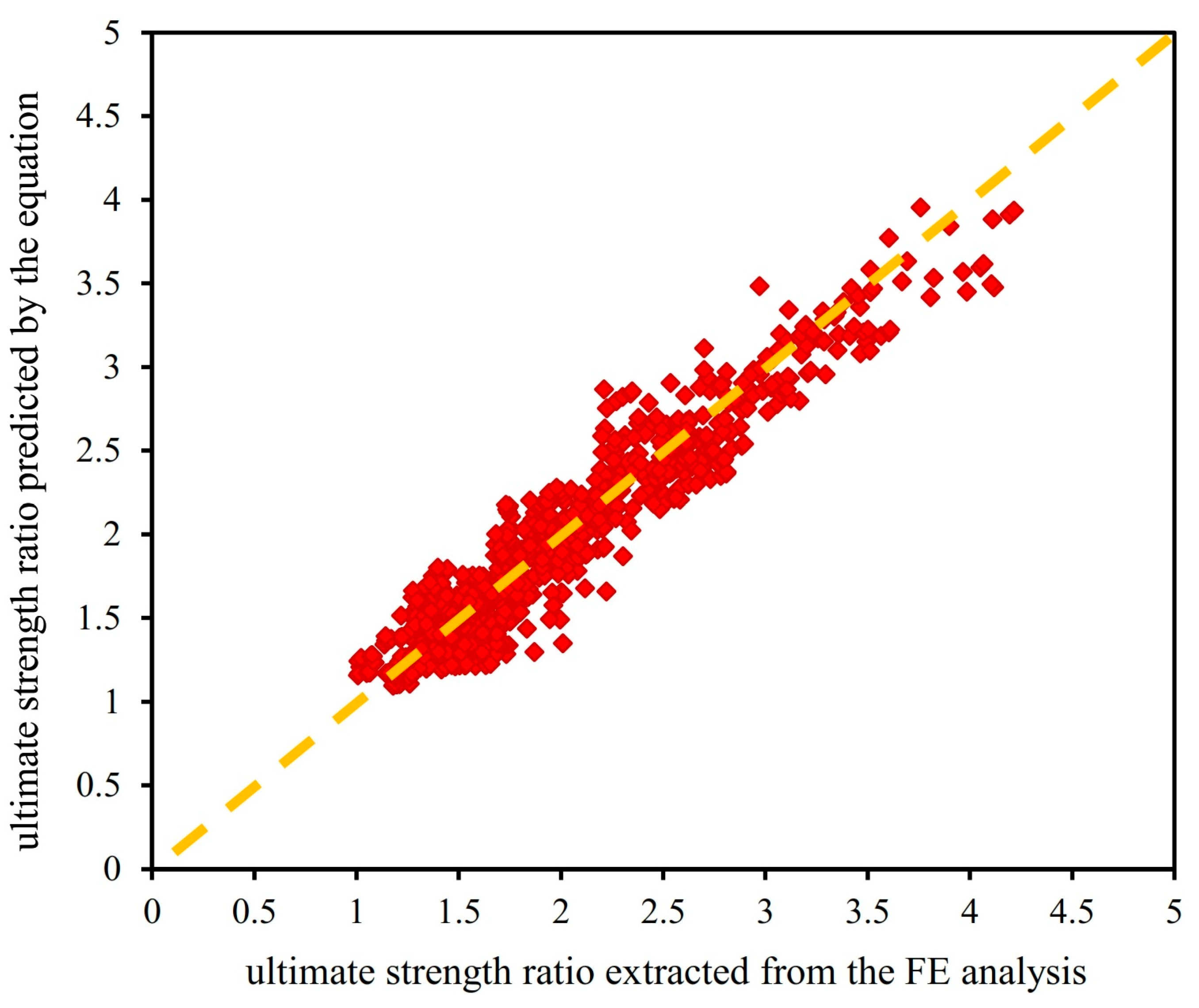
The results of the proposed formula for the strength ratios at room and fire conditions were compared with the associated values obtained from the FE analysis, as shown in Figure 17. It was observed that the values obtained from the proposed equations were in high agreement with those from the FE simulations.
Based on the evaluation of the formulas with the values of R2 (R2 = 0.91), and Figure 17, it can be concluded that the proposed formula can be reliably used for designing external-plate-reinforced K-joints under ambient and various fire conditions.

6. Conclusions

After introducing and validating the proposed FE model via 13 available experimental tests conducted by the present and other researchers, 1057 K-joints reinforced with outer plates were generated and analyzed. The following concluding observations can be made:
The ultimate strength remarkably increases with the increase in the plate thickness and length. It can be seen that the plate can increase the strength by up to 319%.
The results show that the increase in the brace angle and γ leads to the decrease in the stiffness and strength. On the contrary, the increase in the β and τ results in the increase in the stiffness and strength. Moreover, the effect of the ξ on the strength is slight.
The stiffener can considerably improve the ductility of the joints at elevated temperatures.
In the unreinforced joints, the deformations are local. They happen in the joint intersection. But, in the reinforced joints, the deformations are more global. They happen in the plate and more regions of the chord wall.
The increase in the temperatures notably leads to the decrease in the stiffness and ultimate strength. Also, the decrease in them is more considerable at temperatures of more than 400 °C, since the yield stress of the steel members notably decreases at temperatures of more than 400 °C.
A practical formula, based on the yield volume model, is proposed to determine the ultimate strength of CHS K-joints reinforced with the external plate under normal and different fire conditions. The formula can be reliably applied for designing and retrofitting K-joints.

Author Contributions

Conceptualization, H.N.; software, H.N. and A.Y.; validation, H.N.; investigation, H.N. and A.Y.; writing—original draft, H.N.; supervision, H.N. All authors have read and agreed to the published version of the manuscript.

Funding

This research received no external funding.

Data Availability Statement

All of the data are presented in the paper.

Acknowledgments

The authors gratefully acknowledge the useful comments of anonymous reviewers on the draft version of this paper.

Conflicts of Interest

The authors declare no conflict of interest.

References

  1. Pan, Z.; Wu, G.; Si, F.; Shang, J.; Zhou, H.; Li, Q.; Zhou, T. Parametric study on SCF distribution along the weld toe of internally ring-stiffened two-planar tubular KK joints under axial loading. Ocean Eng. 2022, 248, 110826. [Google Scholar] [CrossRef]
  2. He, S.; Shao, Y.; Zhang, H.; Wang, Q. Parametric study on performance of circular tubular K-joints at elevated temperature. Fire Saf. J. 2015, 71, 174–186. [Google Scholar] [CrossRef]
  3. Li, W.; Zhang, S.; Huo, W.; Bai, Y.; Zhu, L. Axial compression strength of steel CHS X-joints retrofittedwith external stiffeners. J. Construct. Steel Res. 2018, 141, 156–166. [Google Scholar] [CrossRef]
  4. Ding, Y.; Zhu, L.; Zhang, K.; Bai, Y.; Sun, H. CHS X-joints retrofittedby external stiffeners under brace axial tension. Eng. Struct. 2018, 171, 445–452. [Google Scholar] [CrossRef]
  5. Zhu, L.; Han, S.; Song, Q.; Ma, L.; Wei, Y.; Li, S. Experimental study of the axial compressive strength of CHS T-joints reinforced with external stiffening rings. Thin-Walled Struct. 2016, 98, 245–251. [Google Scholar] [CrossRef]
  6. Nassiraei, H.; Yara, A. Numerical analysis of local joint flexibility of K-joints with external plates under axial loads in offshore tubular structures. J. Mar. Sci. Appl. 2022, 21, 134–144. [Google Scholar] [CrossRef]
  7. Azari-Dodaran, N.; Ahmadi, H. A numerical study on the ultimate load of offshore two-planar tubular TT-joints reinforced with internal ring stiffeners at fire-induced elevated temperatures. Ocean Eng. 2021, 230, 108797. [Google Scholar] [CrossRef]
  8. Fu, Y.; Tong, L.; He, L.; Zhao, X.L. Experimental and numerical investigation on behavior of CFRP-retrofittedcircular hollow section gap K-joints. Thin-Walled Struct. 2016, 102, 80–97. [Google Scholar] [CrossRef]
  9. Gao, F.; Tang, Z.; Guan, X.; Zhu, H.; Chen, Z. Ultimate strength of tubular T-joints reinforced with doubler plates after fire exposure. Thin-Walled Struct. 2018, 132, 616–628. [Google Scholar] [CrossRef]
  10. Yang, J.; Shao, Y.; Chen, C. Static strength of chord reinforced tubular Y-joints under axial loading. Mar. Struct. 2012, 29, 226–245. [Google Scholar] [CrossRef]
  11. Wu, Q.; Zheng, Q.; Chen, K.; Nakamura, S. Study on fatigue performance of concrete-filled steel tubular K-joints with internal studs. J. Const. Steel Res. 2023, 200, 107662. [Google Scholar] [CrossRef]
  12. Nassiraei, H. Static strength of tubular T/Y-joints reinforced with collar plates at fire induced elevated temperature. Mar. Struct. 2019, 67, 102635. [Google Scholar] [CrossRef]
  13. Nassiraei, H. Probability distribution models for the ultimate strength of tubular T/Y-joints reinforced with collar plates at room and different fire conditions. Ocean Eng. 2023, 270, 113557. [Google Scholar] [CrossRef]
  14. Nassiraei, H.; Rezadoost, P. Probabilistic analysis of the ultimate strength of tubular X-joints stiffened with outer ring at ambient and elevated temperatures. Ocean Eng. 2022, 248, 110744. [Google Scholar] [CrossRef]
  15. Zhou, F.; Chen, Y.; Wang, W.; Xie, W.; Ying, T.; Yue, G. Investigation of hot spot stress for welded tubular K-joints with stiffeners. J. Constr. Steel Res. 2022, 197, 107452. [Google Scholar] [CrossRef]
  16. He, S.; Shao, Y.; Zhang, H. Evaluation on fire resistance of tubular K-joints based on critical temperature method. J. Constr. Steel Res. 2015, 115, 398–406. [Google Scholar] [CrossRef]
  17. He, S.B.; Shao, Y.B.; Zhang, H.Y.; Yang, D.P.; Long, F.L. Experimental study on circular hollow section (CHS) tubular K-joints at elevated temperature. Eng. Fail. Anal. 2013, 34, 204–216. [Google Scholar] [CrossRef]
  18. Ozyurt, E.; Wang, Y.C.; Tan, K.H. Elevated temperature resistance of welded tubular joints under axial load in the brace member. Eng. Struct. 2014, 59, 574–586. [Google Scholar] [CrossRef]
  19. Ozyurt, E.; Wang, Y.C. Resistance of T-and K-joints to tubular members at elevated temperatures. In Applications of Structural Fire Engineering; CRC Press: New York, NY, USA, 2013. [Google Scholar]
  20. Xu, J.; Wu, S.; Han, J.; Wang, J.; Li, Z. Post-earthquake fire resistance of stainless steel K-joints considering gradient temperature effect. J. Constr. Steel Res. 2022, 192, 107219. [Google Scholar] [CrossRef]
  21. Shao, Y.; He, S.; Yang, D. Prediction on static strength for CHS tubular K-joints at elevated temperature. KSCE J. Civ. Eng. 2017, 21, 900–911. [Google Scholar] [CrossRef]
  22. Chen, C.; Chen, Y.; Shao, Y.; Chung, K.F.; Hu, Y. Fire resistance and design assessment of Q355 circular hollow section joints. J. Constr. Steel Res. 2023, 201, 107702. [Google Scholar] [CrossRef]
  23. Lan, X.; Huang, Y.; Chan, T.M.; Young, B. Static strength of stainless steel K-and N-joints at elevated temperatures. Thin-Walled Struct. 2018, 122, 501–509. [Google Scholar] [CrossRef]
  24. Bharti, K.; Kumaraswamidhas, L.A.; Das, R.R. A novel optimization approach for bonded tubular gap K-type connections made of FRP composites. Structures 2020, 28, 2135–2145. [Google Scholar] [CrossRef]
  25. Tan, K.H.; Fung, T.C.; Nguyen, M.P. Structural behavior of CHS T-joints subjected to brace axial compression in fire conditions. J. Struct. Eng. 2013, 139, 73–84. [Google Scholar] [CrossRef]
  26. Dodaran, N.A.; Ahmadi, H.; Lotfollahi-Yaghin, M.A. Parametric study on structural behavior of tubular K-joints under axial loading at fire-induced elevated temperatures. Thin-Walled Struct. 2018, 130, 467–486. [Google Scholar] [CrossRef]
  27. Azari-Dodaran, N.; Ahmadi, H.; Zhu, L.; Li, P. Experimental and numerical study of the ultimate load for collar-plate-reinforced tubular K-joints at fire-induced elevated temperatures. Ships Offshore Struct. 2022, 17, 1159–1177. [Google Scholar] [CrossRef]
  28. American Welding Society (AWS). Structural Welding Code: AWS D 1.1; American Welding Society (AWS): Miami, FL, USA, 2015. [Google Scholar]
  29. EN 1993-1-2; Eurocode 3: Design of Steel Structures—Part 1-2: General Rules—Structural Fire Design. British Standard Institute: London, UK, 2005.
  30. Van der Vegte, G.J.; Choo, Y.S.; Liang, J.X.; Zettlemoyer, N.; Liew, J.Y.R. Static strength of T-joints reinforced with doubler or collar plates. II: Numerical simulations. J. Struct. Eng. 2005, 131, 129–138. [Google Scholar] [CrossRef]
  31. Nassiraei, H.; Zhu, L.; Lotfollahi-Yaghin, M.A.; Ahmadi, H. Static strength of tubular X-joints reinforced with collar plate subjected to brace compression. Thin-Walled Struct. 2017, 119, 256–265. [Google Scholar] [CrossRef]
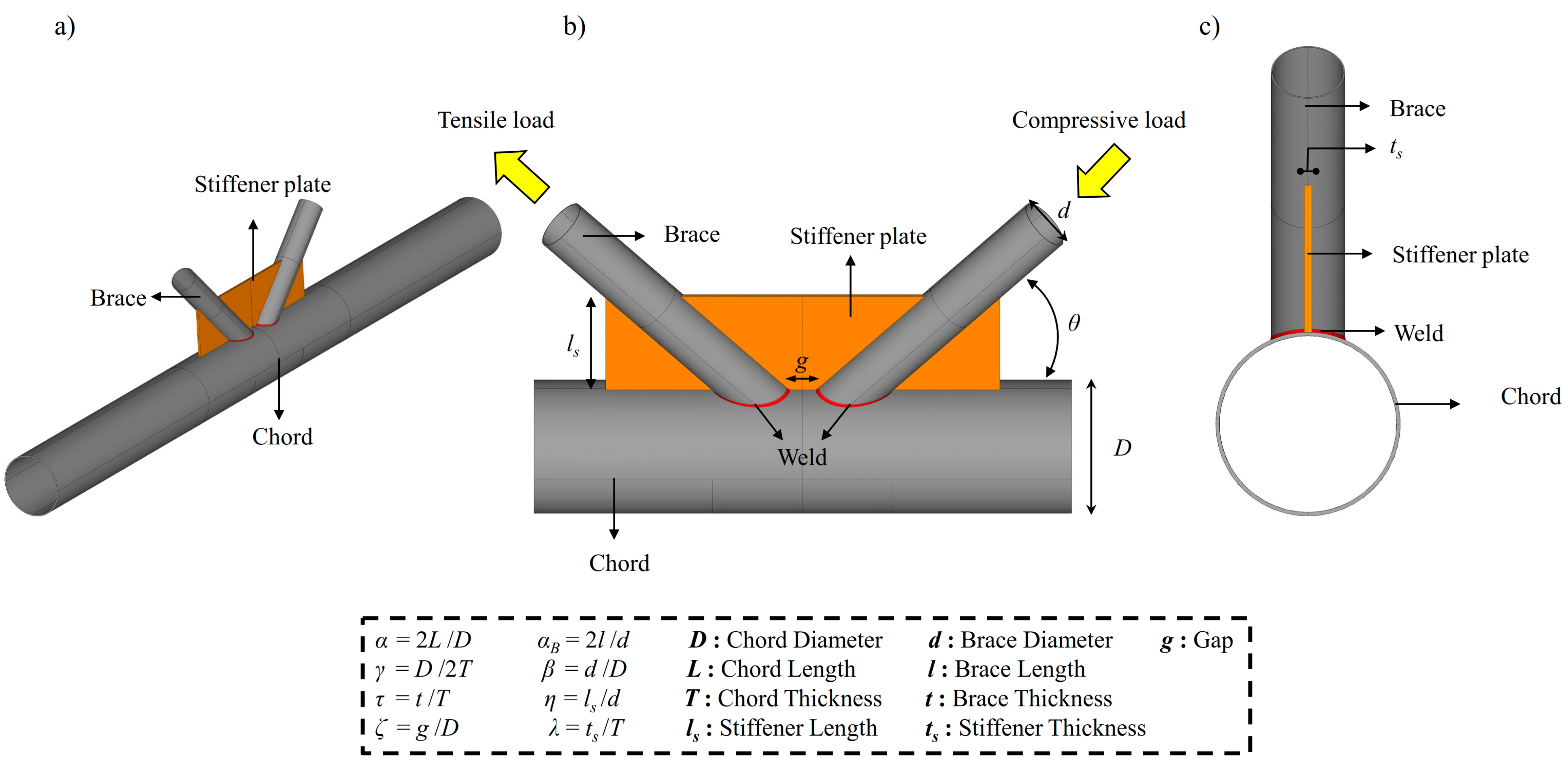
Figure 1. Geometrical notation for K-joint strengthened with external plates, (a) global geometry, (b) geometrical details of the strengthened connection, (c) cross section of the strengthened connection.
Metals 13 01857 g001
Figure 2. Stress and strain relationships at elevated temperatures (according to the recommendations of EN 1993-1-2 [30].
Metals 13 01857 g002
Figure 3. Generated mesh in the reinforced joint ((a,c) show the joint intersection in two different views; (b) shows the reinforced joint).
Metals 13 01857 g003
Figure 4. The experimental data (Fu et al. [8]; Nassiraei et al. [31]; Li et al. [3]; Ding et al. [4]; Zhu et al. [5]; Tan et al. [25]) and present numerical result.
Metals 13 01857 g004
Figure 5. The effect of the brace angle (θ) and high temperatures on the initial stiffness (β = 0.7, γ = 18, τ = 0.8, ξ = 0.4). (ac) are for λ = 1.0. (df) are for λ = 2.0. (gi) are for λ = 3.0.
Metals 13 01857 g005
Figure 6. The effect of the brace angle (θ), plate size (η and λ), and high temperatures on ultimate strength (β = 0.7, γ = 18, τ = 0.8, ξ = 0.4).
Metals 13 01857 g006
Figure 7. The effect of the plate and high temperatures on failure modes (η = 1, λ = 1, β = 0.7, γ = 18, τ = 0.8, ξ = 0.4, and θ = 45°). (ac) are unreinforced joints. (df) are reinforced joint.
Metals 13 01857 g007
Figure 8. The effect of the γ, λ, η, and high temperatures on the initial stiffness (β = 0.3, θ = 50°, τ = 0.6, ξ = 0.5).
Metals 13 01857 g008
Figure 9. The effect of the γ, λ, η, and high temperatures on the ultimate strength (β = 0.3, θ = 50°, τ = 0.6, ξ = 0.5).
Metals 13 01857 g009
Figure 10. The effect of the plate and high temperatures on the failure modes (η = 1, λ = 1, γ = 15, β = 0.3, θ = 50°, τ = 0.6, ξ = 0.5). (ac) are unreinforced joints. (df) are reinforced joint.
Metals 13 01857 g010
Figure 11. The effect of the plate size and high temperatures on the initial stiffness (β = 0.2, γ = 32, τ = 0.5, ξ = 0.3, θ = 40°).
Metals 13 01857 g011
Figure 12. The effect of the plate size and high temperatures on the ultimate strength (γ = 32, τ = 0.5, ξ = 0.3, θ = 40°).
Metals 13 01857 g012
Figure 13. The effect of the τ, plate size, and high temperatures on the ultimate strength (γ = 25, ξ = 0.2, β = 0.4, θ = 45°).
Metals 13 01857 g013
Figure 14. The effect of the ξ, plate size, and high temperatures on the initial stiffness (γ = 12, τ = 0.9, β = 0.9, θ = 60°).
Metals 13 01857 g014
Figure 15. The effect of the ξ, plate size, and high temperatures on the ultimate strength (γ = 12, τ = 0.9, β = 0.9, θ = 60°).
Metals 13 01857 g015
Figure 16. Yield body in strengthened K-connection.
Metals 13 01857 g016
Figure 17. Comparison of the ultimate capacity ratios predicted by the proposed equation with the corresponding values extracted from 1057 FE analyses.
Metals 13 01857 g017
Table 1. Geometrical parameters of experimental tests.
Specimen Joint TypeResearchersD (mm)ls
(mm)
ts (mm)αθ (°)βγτTemperature (°C)
S1KFu et al. [8]219--22.83550.6013.680.7520
S2219--22.83550.6013.680.7520
S3XNassiraei et al. [31]300.03--12.0900.2516.40.9020
S4300.00--12.0900.7317.90.9920
S5XLi et al. [3]299.60303.507.8012.06900.5118.681.0120
S6300.40437.37.9011.96900.7318.701.0020
S7XDing et al. [4]304.00152811.86900.2518.680.7120
S8298.03302812.06900.5117.901.0420
S9TZhu et al. [5]298.00--12.08900.2524.031.1020
S10298.2071.505.312.07900.2524.041.1020
S11TTan et al. [25]244.5--18900.6919.41550
S12244.5--18900.6919.41700
S13244.5--18900.819.41550
Table 2. Material parameters.
Specimenfu0
(MPa)
fu1
(MPa)
fu2
(MPa)
fy0
(MPa)
fy1
(MPa)
fy2
(MPa)
E0
(GPa)
E1
(GPa)
E2
(GPa)
S1473480-310298----
S2473480-310298----
S3460470474270358285206218213.3
S4460469474270298285206203213.3
S5194192212325316301466493414
S6194200212325321301466489414
S7200.3222.3246.5267.7313.3358.3---
S8200.3240246.5267.7295358.3---
S9227224-345470----
S10227224229345470322---
S11355355-380.3380.3-201201-
S12355355-380.3380.3-201201-
S13355355-355355-210210-
Notes: fy0: yield stress of chord; fy1: yield stress of brace; fy2: yield stress of the plate; fu0: ultimate stress of chord; fu1: ultimate stress of brace; fu2: ultimate stress of the plate.
Table 3. Comparison between numerical and experimental results.
SpecimenFu, test (kN)Fu, num (kN)Fu, num/Fu, test
S1542515.630.95
S2542573.631.05
S3174.631700.97
S4319.41311.440.97
S5256.20285.170.89
S6374.65404.4741.07
S7194.7211.311.08
S8308.1354.991.15
S98590.201.06
S10100.2110.4421.10
S11180.9173.40.95
S1276.477.901.01
S13216.52201.01
Disclaimer/Publisher’s Note: The statements, opinions and data contained in all publications are solely those of the individual author(s) and contributor(s) and not of MDPI and/or the editor(s). MDPI and/or the editor(s) disclaim responsibility for any injury to people or property resulting from any ideas, methods, instructions or products referred to in the content.