Review

Very High Cycle Fatigue of Welds: A Review

by
Andrew England
*,
Athanasios Toumpis
and
Yevgen Gorash
*
Department of Mechanical & Aerospace Engineering, University of Strathclyde, 75 Montrose Street, Glasgow G1 1XJ, UK
*
Authors to whom correspondence should be addressed.
Metals 2023, 13(11), 1860; https://doi.org/10.3390/met13111860
Submission received: 10 October 2023 / Revised: 30 October 2023 / Accepted: 3 November 2023 / Published: 7 November 2023

Abstract

:
The design life of welded structures and components extends into the very high cycle fatigue (VHCF) regime across various applications. However, the availability of data on the fatigue behaviour of welded joints in the VHCF regime is limited, particularly when compared to the low and high cycle fatigue regimes. The development of ultrasonic fatigue testing equipment has accelerated fatigue testing and allowed for the VHCF properties of welds to be investigated in a feasible timeframe. In the present review, the emerging research concerning the VHCF behaviour of welds of various steels and non-ferrous alloys are individually explored. Overall, it is observed that welded joints have significantly lower fatigue strength than the base metal in the VHCF regime and that welding defects have a considerable influence on fatigue strength. Through the discussion of the relevant literature, important findings concerning the effects of specimen geometry and fatigue improvement methods are underlined. Furthermore, the guidance provided within design standards is compared, and some examples of VHCF failures of in-service components are highlighted. Finally, perspectives on future directions of investigation are put forward with the aim of encouraging further research in the field of VHCF of welds.

1. Introduction

Fatigue failure of metals is a challenge faced across almost all industries; it is commonly estimated that fatigue damage is responsible for 90% of all in-service mechanical failures [1]. Repeated loading at stresses less than the yield strength of the material can lead to the initiation and propagation of cracks, resulting in a complete fracture [2]. Welded joints are generally the critical location in the structural integrity assessments of cyclically loaded components [3]. The fatigue strength of fusion-welded joints is almost always lower than the corresponding base metal due to several factors [4]. Unless it is removed by machining, the abrupt change in geometry caused by the weld toe creates a stress concentration region [5]. The thermal contraction during cooling generates tensile residual stresses of a magnitude similar to the yield strength of the base metal, significantly reducing the fatigue strength of the welded joint [6]. Additionally, the inhomogeneous microstructures and defects commonly found in welded joints make them susceptible to fatigue failure during service [7].
Fatigue regimes are generally classified by the number of cycles to failure: low cycle fatigue (LCF) as up to 104 cycles; high cycle fatigue (HCF) as 104 to 107 cycles; and very high cycle fatigue (VHCF) as over 107 cycles [8]. These fatigue regimes are displayed schematically in the form of an S–N curve in Figure 1. In the LCF regime, applied stresses are greater than the yield strength of the material; therefore, significant plastic deformation occurs in each loading cycle [9]. The HCF regime is generally characterised by stresses less than the yield strength and purely elastic deformation in each loading cycle [8]. It is a classical assumption that below a certain constant amplitude stress, fatigue failure will never occur, a concept known as the fatigue limit [10]. The fatigue limit appears on an S–N curve as a horizontal asymptote (Figure 1). The existence of a fatigue limit between 106 and 107 cycles has been proven invalid [11], and subsequently, the VHCF of metals has become a well-established research field.
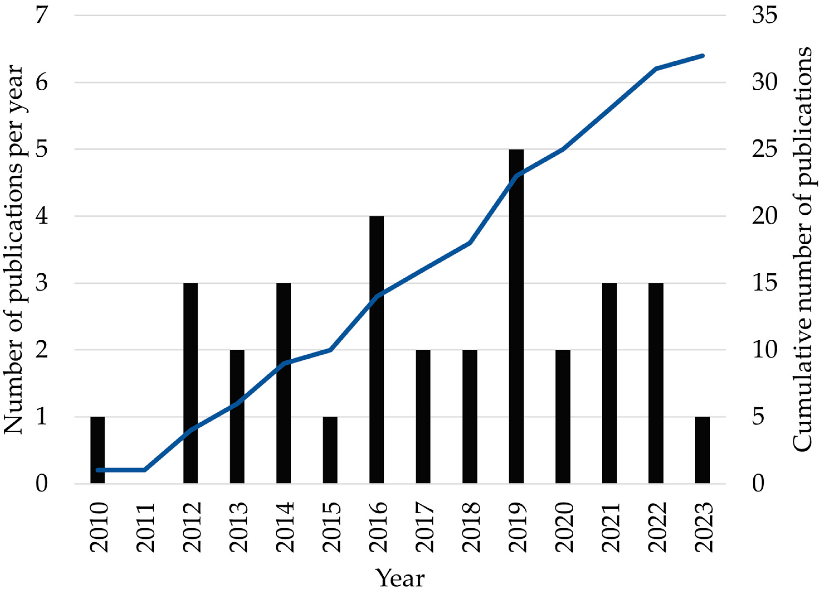
Welded structures have service lives in the VHCF regime across a range of applications, including bridges, automotive components, and heavy industry equipment [12,13,14]. To ensure the safe operation of engineering components, machines, and structures, the VHCF behaviour of welds has become an emerging field of research following the first published paper on the topic in 2010 [15]. Figure 2 reveals that only a few papers have been published each year, with a relatively steady interest since 2012. For this review, publications were gathered from an extensive range of databases, including Scopus, Web of Science, and Google Scholar.
The present paper represents the first review of the topic of VHCF of welds, with the primary aim of acting as a comprehensive introduction to the field. The subjects of ultrasonic fatigue testing (UFT) and the VHCF of metals are also briefly discussed so that the main topic can be better understood. This work also serves to encourage further research in the field of VHCF of welds by identifying crucial knowledge gaps.

2. Ultrasonic Fatigue Testing and Very High Cycle Fatigue of Metals

2.1. The Ultrasonic Fatigue Testing Method

Conducting laboratory-based fatigue testing to the full extent of the VHCF regime in a realistic and economical timeframe is only feasible using UFT, where the loading frequency is typically 20 kHz [16]. Achieving 109 loading cycles using a servo-hydraulic fatigue testing machine at 20 Hz requires over 500 days of continuous loading, but this can be reduced to just 14 h using UFT [17]. Undertaking resonance fatigue testing at 100 Hz allows for the early portion of the VHCF regime to be explored; as an illustration, 5 × 10⁷ cycles can be reached in less than 6 days. Fatigue tests conducted at low frequencies (<150 Hz) will hereafter be referred to as conventional fatigue tests. The frequency of 20 kHz is used for UFT as it is outside of the audible range of the human ear, but greater frequencies than this result in increased cycle counting errors and a reduction in the length of the specimen [18]. It is possible to employ UFT for cyclic bending [19], torsional [20], or multiaxial [21] loading, but only uniaxial tension-compression loading will be considered in this paper.
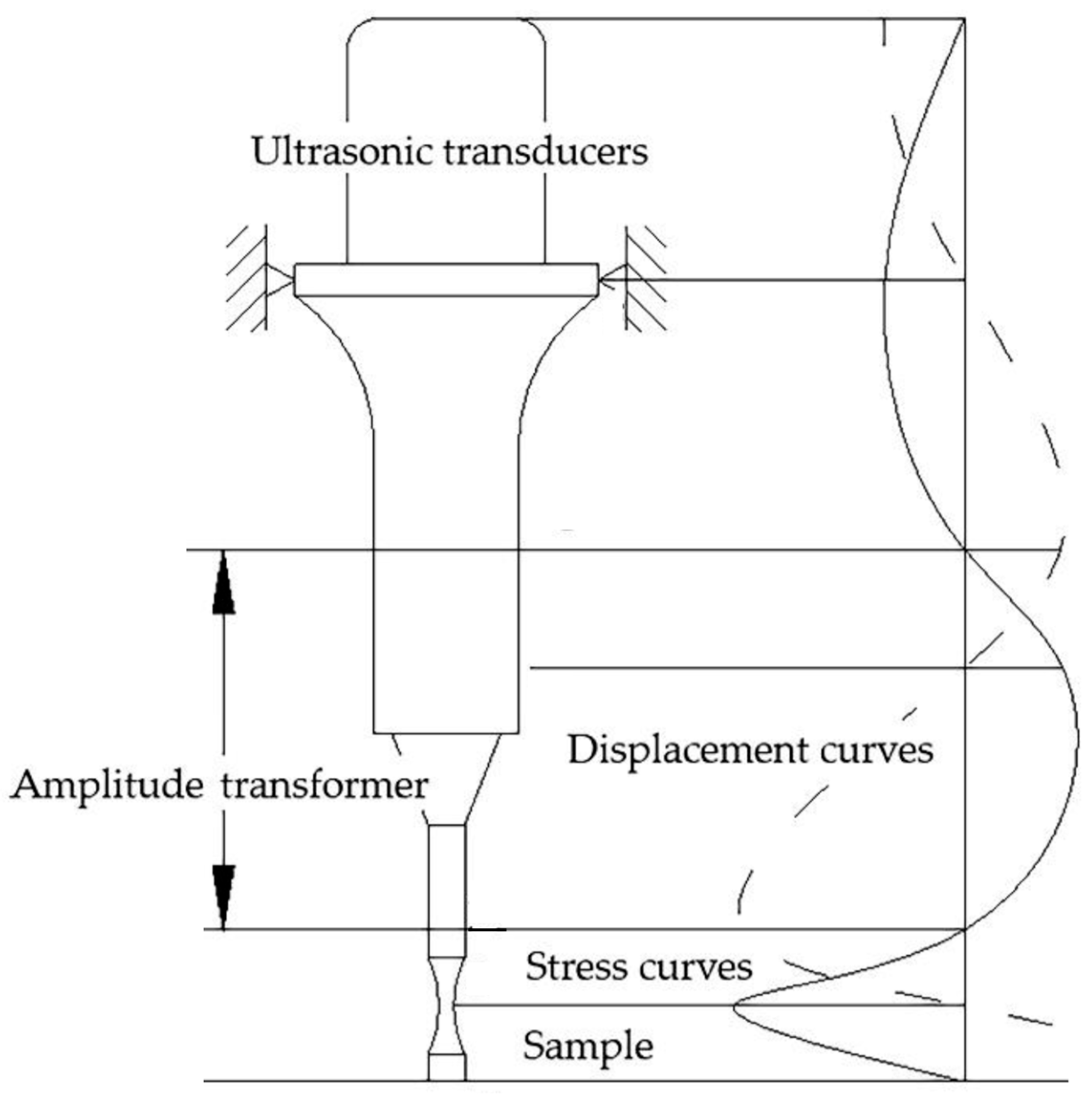
UFT machines (Figure 3) use ultrasonic transducers (usually a piezoelectric actuator) to generate mechanical vibration from an electrical signal [22]. The longitudinal vibration is then amplified as it is transmitted through the booster and horn to the specimen, typically attached by threads [22]. Specimens are excited at their natural frequency; therefore, the maximum stress, but minimum displacement, is experienced at the centre of the specimen. VHCF tests have been demonstrated with both bespoke UFT apparatuses constructed at research institutions and equipment from commercial manufacturers [16].
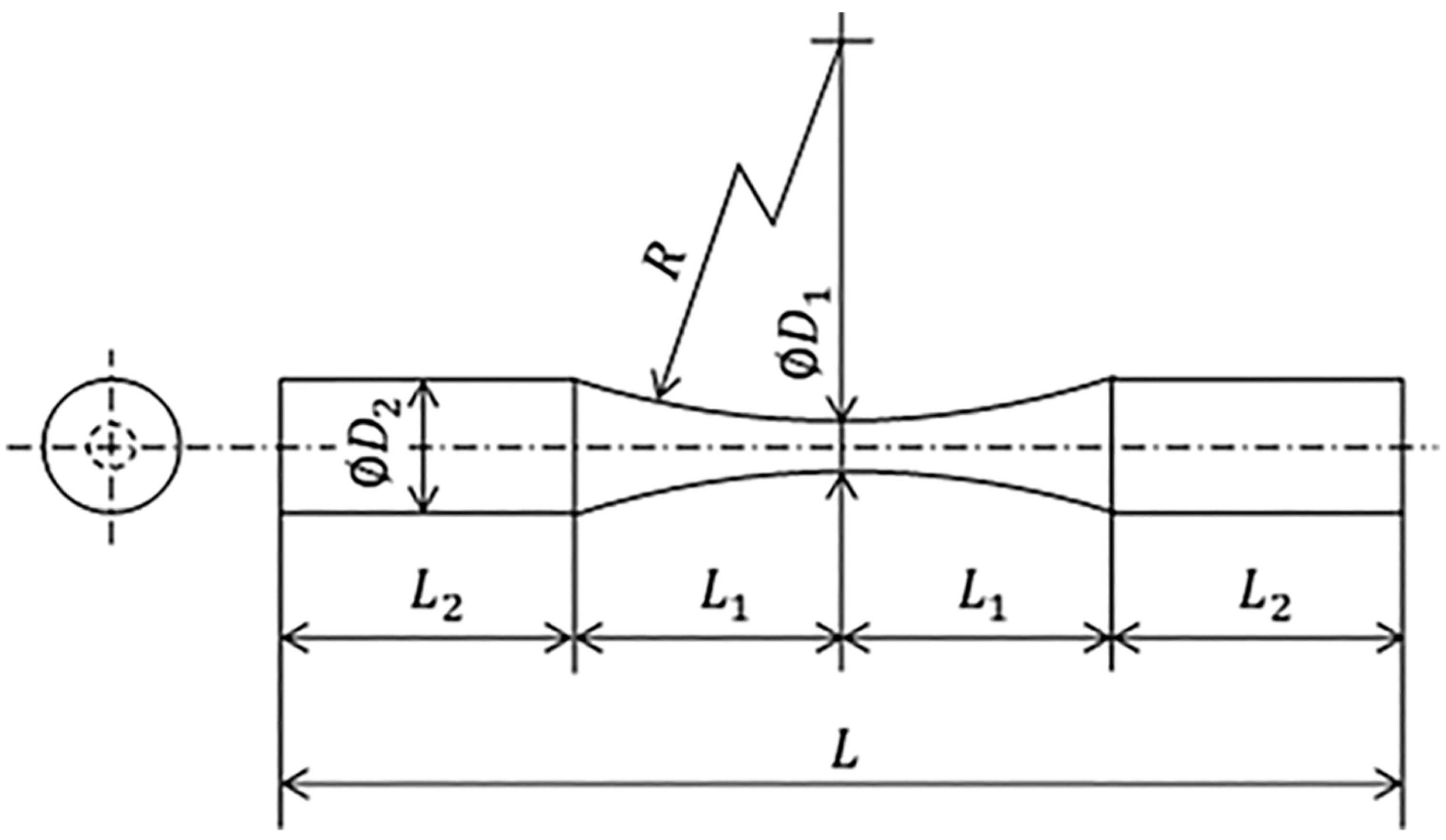
The UFT method was standardised by the Japan Welding Engineering Society in WES 1112 [24]. Within this standard, the procedure for determining dimensions for standard-shaped specimens, e.g., cylindrical hourglass (Figure 4), is specified. Additionally, aspects of the test procedure, such as the tolerance of the resonant frequency and the maximum specimen surface temperature, are detailed [25]. Similar to conventional fatigue testing, UFT can be used to construct an S–N curve of a particular material by testing multiple identical specimens at a range of constant amplitude stress levels.
It has been reported that the fatigue data obtained using UFT are often not comparable to that obtained at conventional frequencies, a phenomenon known as the “frequency effect” [25]. For instance, Bach et al. [26] found a 50% increase in fatigue strength at 20 kHz compared to 120 Hz for C15E low-carbon steel. A wide-ranging review of the frequency effect is provided by Hong et al. [27]. The primary cause of the frequency effect is the sensitivity of flow stress to strain rate for certain crystal lattice structures, especially the body-centred cubic (BCC) structure [28]. Low-carbon steels, which consist primarily of ferrite with a BCC structure, exhibit a significant frequency effect [29,30]. Recently, Guennec et al. [31] proposed a model based on dislocation motion to predict the fatigue limit of carbon steels, depending on the alloy’s wt.% C and the applied loading frequency. The model, validated from results from the literature, showed that as the wt.% C reduces, and consequently, the ferrite grain fraction increases, the severity of the frequency effect increases [31]. A limitation of the model is that it requires the measurement of the fatigue limit, the value of which depends on the selection of the number of cycles defined as a runout, and the number of tests conducted. The frequency effect is not an issue with high-strength steels, since it has been found to diminish as tensile strength increases [32]. Further, the fatigue strength of metallic materials with a face-centred cubic (FCC) lattice structure, e.g., stainless steel or aluminium alloys, demonstrates minimal sensitivity to the loading frequency [27].

2.2. Fatigue Behaviour of Metals at Very High Cycles

The course of the S–N curve in the VHCF regime has been shown to vary between different metals. Mughrabi [33] proposed that the VHCF behaviour of metals can be classified into two different types. “Type I” metallic materials show a relatively little decrease in fatigue strength in the VHCF domain and generally only fail from cracks initiated at the specimen surface [33]. Metals that fall under this category are typically ductile and have homogenous microstructures, for instance, copper alloys and low-carbon steels [8]. It is more likely to observe a fatigue limit for Type I metals due to the slow decline in fatigue strength in the VHCF domain [34].
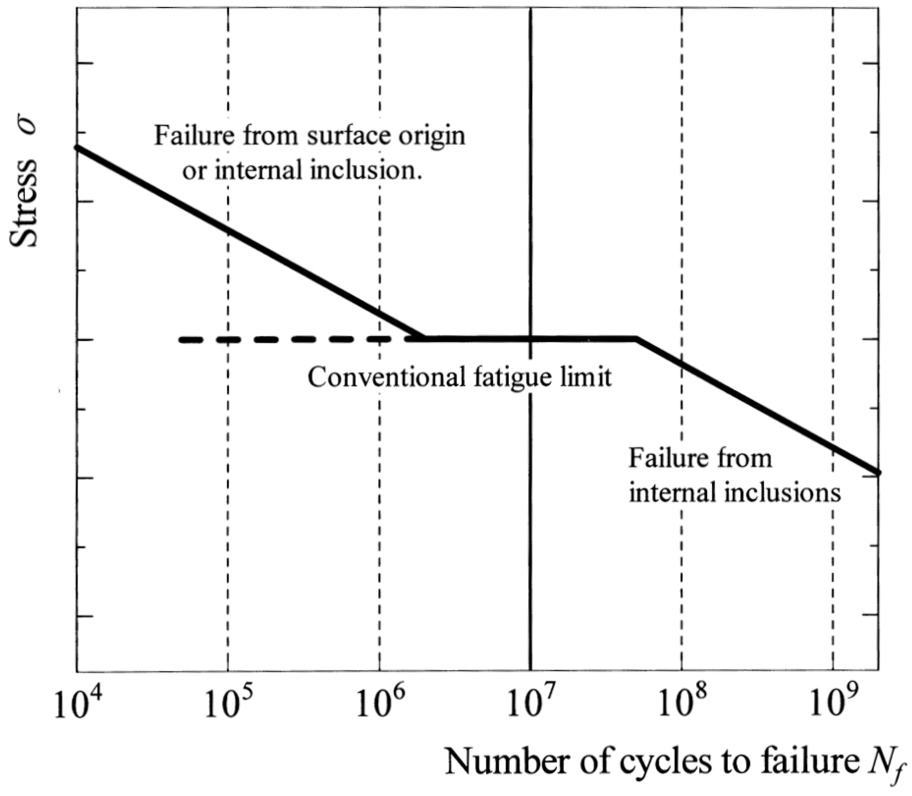
Conversely, the S–N curve of “Type II” metallic materials shows a continuous decrease in the VHCF domain [33]. The fatigue behaviour of this class of materials is influenced by the presence of pores, non-metallic inclusions or secondary phases within their microstructure [8]. A duplex-shaped S–N curve (Figure 5) represents the VHCF behaviour of Type II materials, examples of which include high-strength steels and titanium alloys [33]. Additionally, aluminium alloys do not typically display a fatigue limit [35].
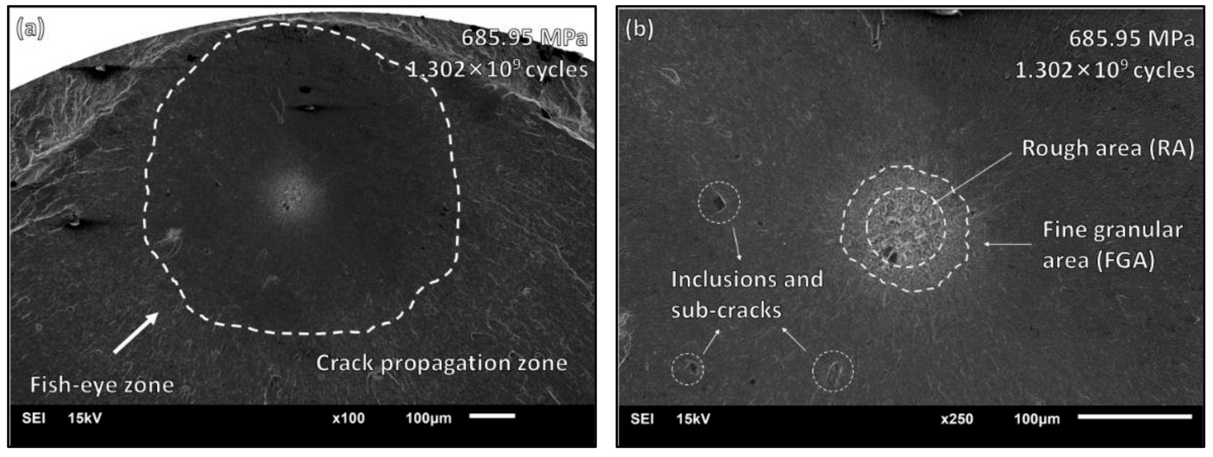
Fatigue cracks tend to initiate in the VHCF domain from internal inclusions for Type II metals, as indicated in Figure 5. The surface of internal inclusion-initiated fractures of Type II metals (Figure 6a) typically shows a distinctive bright region (Figure 6b), known as the fine granular area (FGA) [37]. The formation mechanisms of FGAs are not fully understood, but a thorough review of the current models has been put forward by Li et al. [38]. However, it is agreed that the FGA forms early in cyclic loading and remains the same approximate size throughout most of the fatigue life [39]. Crack growth occurs outward from the FGA to form the fish-eye propagation zone, which is characteristic of VHCF fracture surfaces [40].

3. Very High Cycle Fatigue Performance of Welds

Investigating the VHCF performance of welded joints of metals has become feasible due to the maturity of the UFT method. Compared to the testing of unwelded metals, the study of welded joints is less explored, although there are a limited number of published papers concerning this subject area. This section will summarise the research conducted concerning the VHCF properties of welded joints, categorised by material type.

3.1. Low-Carbon Steels

Low-carbon steels are typically categorised as Type I materials, showing a low decrease in fatigue strength in the VHCF domain due to their homogenous microstructure and ductility [8,33]. However, welded joints of low-carbon steels cannot be assumed to be Type I materials. This is because they frequently contain inclusions and pores that are characteristic of Type II materials, which exhibit a significant reduction in fatigue strength in the VHCF regime [7,8].
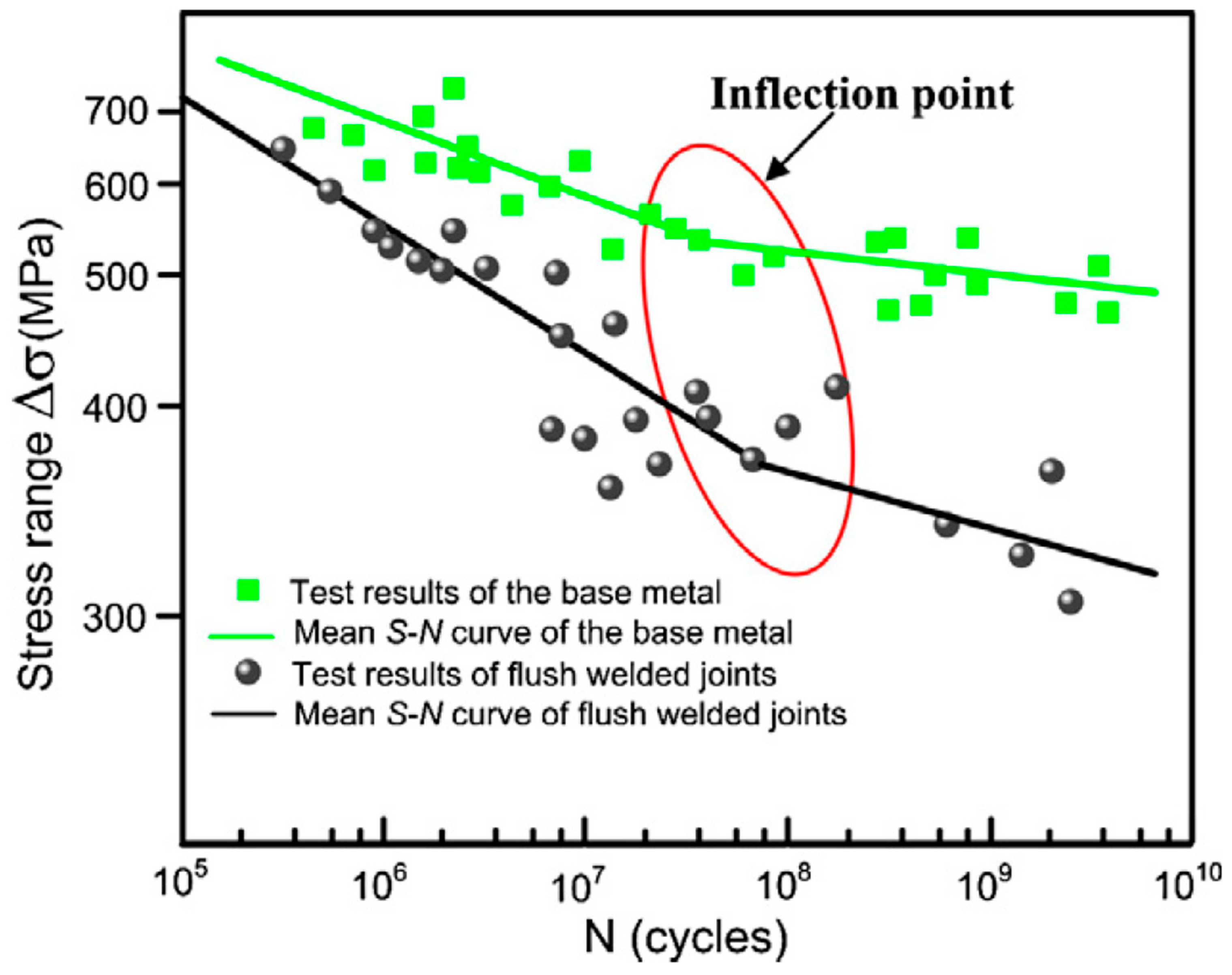
Weldments of low-carbon steel are commonly used in applications that experience VHCF, such as bridges [12] and heavy industry equipment [14]. In this context, they have been the subject of some of the first research on the VHCF of welds. Zhao et al. [41] investigated the VHCF performance of EH36 structural steel base metal and butt welds fabricated using flux-core arc welding (FCAW), with the welds ground flush before testing. Figure 7 displays the test results of the base metal and welded specimens under fully reversed axial loading at 20 kHz at room temperature. Although the slope of the S–N curve reduces in the VHCF regime, no fatigue limit was observed, and multiple fatigue failures occurred above 109 cycles for both specimen types. The fatigue strength of the welded joints was less than that of the base metal, especially as the number of cycles to failure increased. Fractography revealed that the fatigue crack initiation sites in welded specimens were inclusions and pores; hence, these were the principal reasons for the reduction in fatigue strength [41]. One limitation of this study is the absence of recorded runout specimens, which would have aided in the statistical evaluation of the results [42].
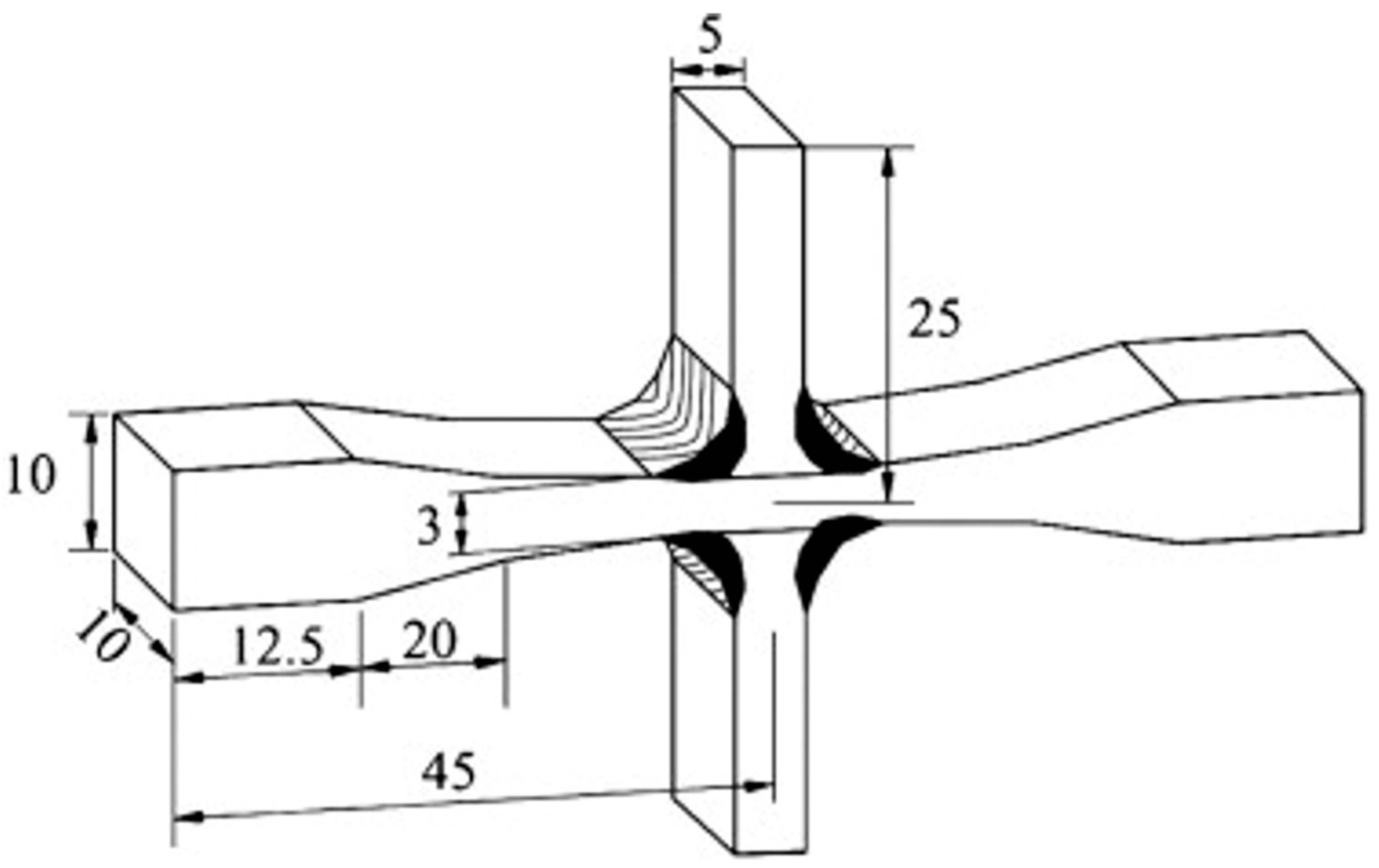
The VHCF properties of cruciform arc-welded joints of Q235 and Q345 structural steels were studied by Yin et al. [15]. The cruciform joints, shown in Figure 8, were comprised of four non-load-carrying fillet welds and assessed using UFT. A continually decreasing S–N curve in the VHCF regime was observed for welded specimens of both Q235 and Q345. Failures occurred above 109 cycles, and no runout specimens were reported; hence, a fatigue limit was not observed for the cruciform joints and cracks initiated at the weld toes from slag inclusions or machining marks. Additionally, the effect of ultrasonic peening treatment (UPT) was investigated; it was found that the VHCF strength was significantly increased for welded joints of both base metals due to grain refinement and the generation of beneficial compressive residual stresses [15]. Cylindrical, hourglass-shaped specimens of Q345 base metal and arc-welded joints were tested using UFT by He et al. [12], and a fatigue limit was not observed for either specimen type. The fatigue strength of the welded joints was found to be significantly lower in the VHCF domain when compared to the base metal due to cracks initiating owing to lack of penetration, slag inclusion, and gas pore defects [12].
UFT of as-welded butt joints of 16Mn structural steel was conducted by Liu et al. [43]. A similar geometry to the standard hourglass specimen recommended by WES 1112 [24] was used, with a circumferential gas tungsten arc weld (GTAW) in the central gauge section. Fatigue failures were observed in the VHCF regime, with cracks initiating at either the welding stop/start point or the weld toe due to the geometric stress concentration in these regions. Welded joints subjected to UPT were also tested, but showed only a small increase in fatigue strength, in contrast to the results of Yin et al. [15].
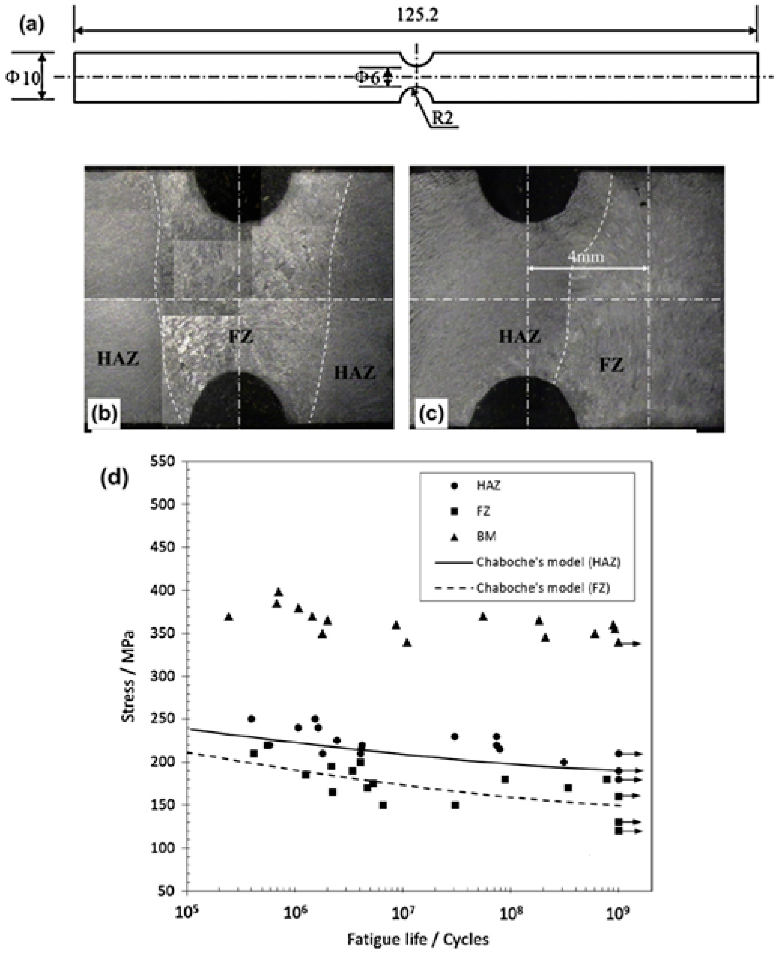
He et al. [44] investigated the VHCF behaviour of Q345 welds joined by shielded metal arc welding (SMAW). A specially designed semi-circular notched UFT specimen (Figure 9) was used to discretely evaluate the fatigue behaviour of the base metal, heat-affected zone (HAZ), and fusion zone (FZ). The base metal had significantly greater fatigue strength than the HAZ and FZ in the VHCF regime, with a decrease of approx. 55% and 60%, respectively (Figure 9d). The onset of fatigue failure was assessed by monitoring the natural frequency of specimens during testing since crack propagation reduces the stiffness of a specimen, hence the natural frequency [45]. Through this method, it was revealed that the fatigue crack initiation stage was significantly shorter for the FZ when compared to the HAZ, as cracks readily propagated from pores and inclusions early in the fatigue life of specimens [44]. While the study [44] examined the effect of internal defects, the notched specimen design omitted the weld cap and root. Thus, the potential influence of external defects, such as undercuts or inadequate root penetration [46], was overlooked.
The dependence of the microstructure on the VHCF behaviour of low-carbon steel welds was shown by Nishikawa and Furuya [47]. Heat treatments were used to simulate the temperature cycle experienced by different regions of the HAZ of low-carbon steel (0.15% wt.%C). Specimens consisting of either fine- or coarse-grained microstructures were produced by altering the maximum temperature and cooling rate. The fine-grained specimens revealed a distinct fatigue limit, with no failures occurring above 106 cycles. In contrast, the coarse-grained specimens showed a continually decreasing S–N curve in the VHCF regime due to internally originated fractures [47].
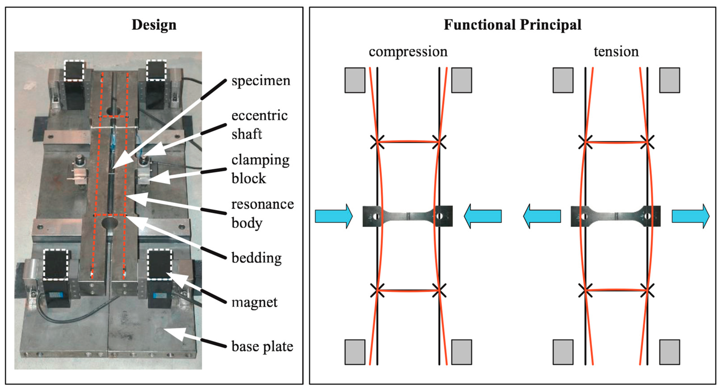
Schaumann and Steppeler [48] used a resonance-based fatigue testing machine to assess the VHCF behaviour of gas metal arc welding (GMAW) butt joints of S355J2+N structural steel. Fatigue testing was conducted at 390 Hz, and the machine configuration (Figure 10) allowed for the testing of welded joints with a 25 mm × 4 mm cross-section in the gauge length, considerably greater than what is possible with UFT [49]. Testing at 390 Hz was shown to have no influence on the fatigue strength of the welded joints in comparison to tests conducted using conventional servo-hydraulic fatigue testing at 20 Hz. The elevated frequency of 390 Hz allowed for tests to be conducted in the VHCF domain, up to a runout value of 5 × 10⁸ cycles. However, the specimens displayed a fatigue limit at 3 × 10⁶ cycles [48]. A fatigue limit at 107 cycles was observed by Gao et al. [50] for FCAW cruciform joints of Q355B steel, tested at 110 Hz to a runout value of 2 × 10⁸ cycles.
A summary of the research carried out on the VHCF behaviour of low-carbon steel welded joints is provided in Table 1. Generally, it is found that welds of this class of metal show no fatigue limit before 107 cycles. Low-carbon steel welds have a reduced VHCF strength when compared to the corresponding base metals, regardless of the welding method used [12,41,43,44]. Almost all this research is conducted using structural steels with a yield strength of approx. 350 MPa (e.g., Q345, S355, EH36), and consequently future research should focus on other, preferably higher-strength grades. The effect of the loading frequency should be considered in subsequent investigations where UFT is employed, as the fatigue strength of low-carbon steels has been identified as showing a strong dependence on this aspect [31].

3.2. Alloy Steels

Alloy steels include alloying elements in appreciable amounts, in addition to carbon, that serve to improve mechanical properties [51]. They are generally used in applications where increased strength, hardness, and corrosion resistance are required compared to unalloyed low-carbon steels [51]. Alloy steels often feature inclusions or secondary phases, characteristics of Type II materials in the VHCF regime [8]. The additional alloying elements result in a higher potential for solidification cracking or HAZ softening post-welding; thus, preheating or post-weld heat treatments may be required [52]. Alloy steel welds are used in a range of applications that are subjected to VHCF, e.g., automotive struts and suspension components [13] and impeller blades [53].
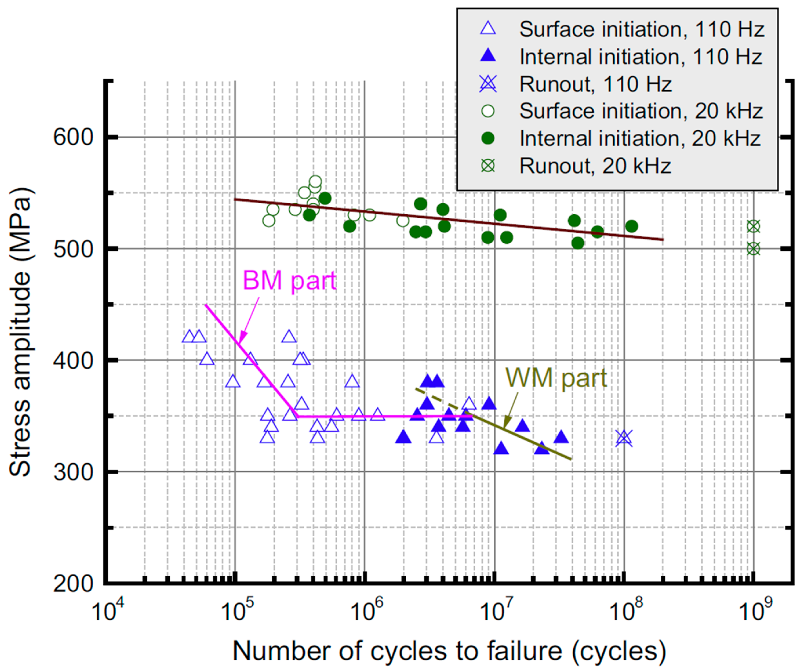
As detailed in Section 2.1, the frequency effect is a significant issue with UFT and, consequently, characterising material behaviour in the VHCF regime. Despite this, the only existing research on the frequency effect with UFT of welded joints was conducted by Zhu et al. [53], who tested submerged arc welding (SAW) joints of 25Cr2Ni2MoV alloy steel at 110 Hz and 20 kHz. Cylindrical, dog-bone-shaped specimens were used so that the base metal, HAZ, and FZ regions all experienced the same stress during cyclic loading. As shown in Figure 11, the fatigue strength and fracture initiation sites of the welded joints showed sensitivity to the loading frequency, especially as the number of cycles to failure increased. The percentage increase in fatigue strength from 110 Hz to 20 kHz was 30% at 105 cycles, rising to 75% at 108 cycles. Additionally, fatigue cracks tended to initiate in the base metal at 110 Hz, only transitioning to the FZ at lower stress amplitudes above 2 × 10⁶ cycles. In contrast, the majority of specimens tested at 20 kHz failed from the FZ, regardless of the stress amplitude applied. For both test frequencies, fatigue cracks initiated at the specimen surface at higher stress amplitudes, but from interior pores and inclusions at lower stress amplitudes. The volume of material subjected to >90% of maximum applied stress, known as the risk volume [54], differed between the specimens tested at each frequency, as well as the proportion comprised by each weld region [53]. These factors limit the certainty that any difference in fatigue behaviour can be solely attributed to the loading frequency.
Cylindrical, dog-bone-shaped specimens with diameters of 5 mm and 3 mm were used to assess the size effect in UFT of welded joints by Zhu et al. [55]. For the same 25Cr2Ni2MoV alloy steel welds as detailed above [53], an increase of approx. 20% was observed in the fatigue strength at 107 cycles for the 3 mm diameter specimens compared to the 5 mm diameter specimens. This phenomenon was attributed to the increased probability of the presence of a larger defect, which a crack can initiate from at a lower stress [55]. SAW joints of the same alloy steel, 25Cr2Ni2MoV, were used to study the heat dissipation during UFT of welds [56]. The heat dissipation behaviour was similar for base metal and welded specimens during ultrasonic loading. The maximum surface temperature of the specimens followed the same trend for continuous and intermittent loading; an initial temperature increase was followed by a stable period. As crack propagation occurred, an increase in maximum surface temperature was observed, and its location correlated with the fracture site. The position of maximum temperature varied throughout tests in the welded specimen, whereas it remained fixed at the centre of base metal specimens [56].
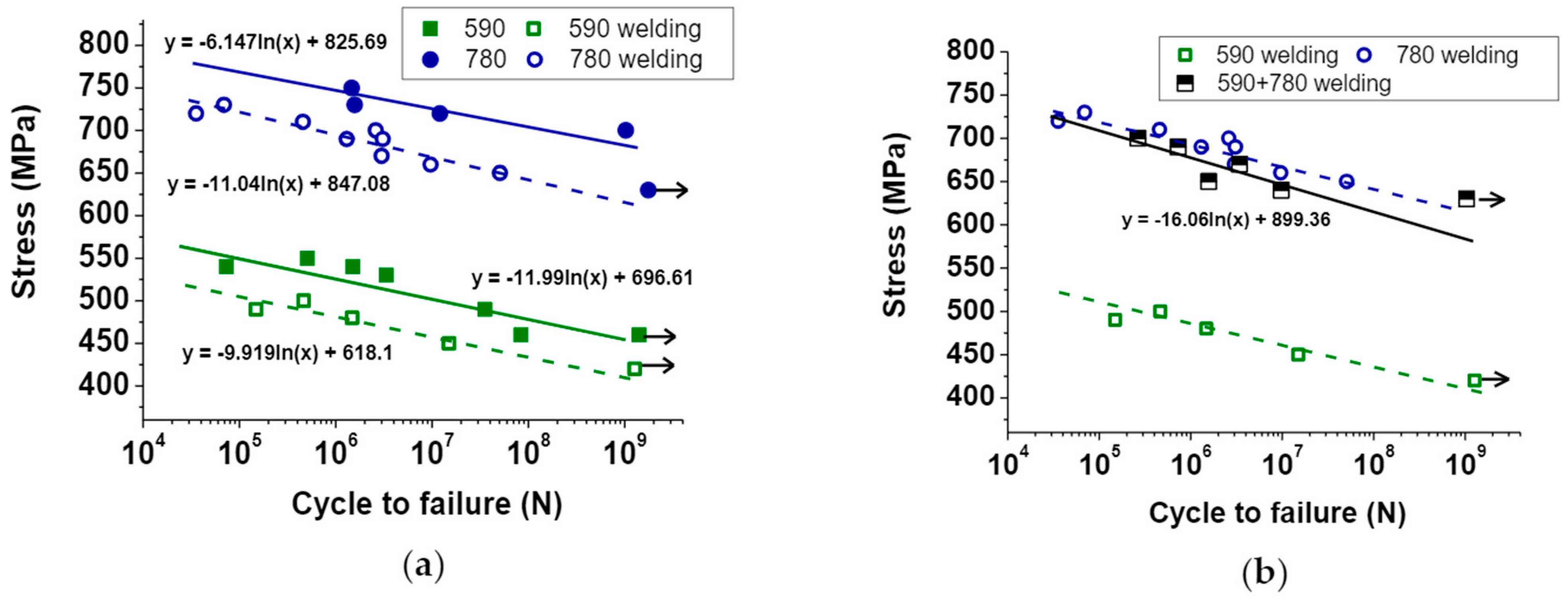
The determination of a potential fatigue limit is the focus of a range of research on alloy steel welds. Yeom et al. [13] investigated the VHCF behaviour of GMAW joints of ferritic-bainitic alloy steels 590 FB and 780 FB. Rectangular cross-section dog-bone specimens with the weld bead removed were tested using UFT in addition to base metal specimens. Neither the base metal nor the respective welded joints displayed a fatigue limit below 109 cycles, as shown in Figure 12a. Only a minimal decrease in the VHCF strength (approx. 8%) was measured for both 590 FB and 780 FB due to welding, contrary to other research comparing welded joints to base metals in the VHCF domain [41,43,44]. As depicted in Figure 12b, dissimilar welds of 590 FB and 780 FB showed comparable VHCF strength to 780 FB welds [13]. Moreover, it was found that all specimens that fractured above 107 cycles exhibited crack initiation at a single point on the specimen surface [13]. A limited number of specimens were tested for each base metal and welded joint, restricting any conclusions that could be established.
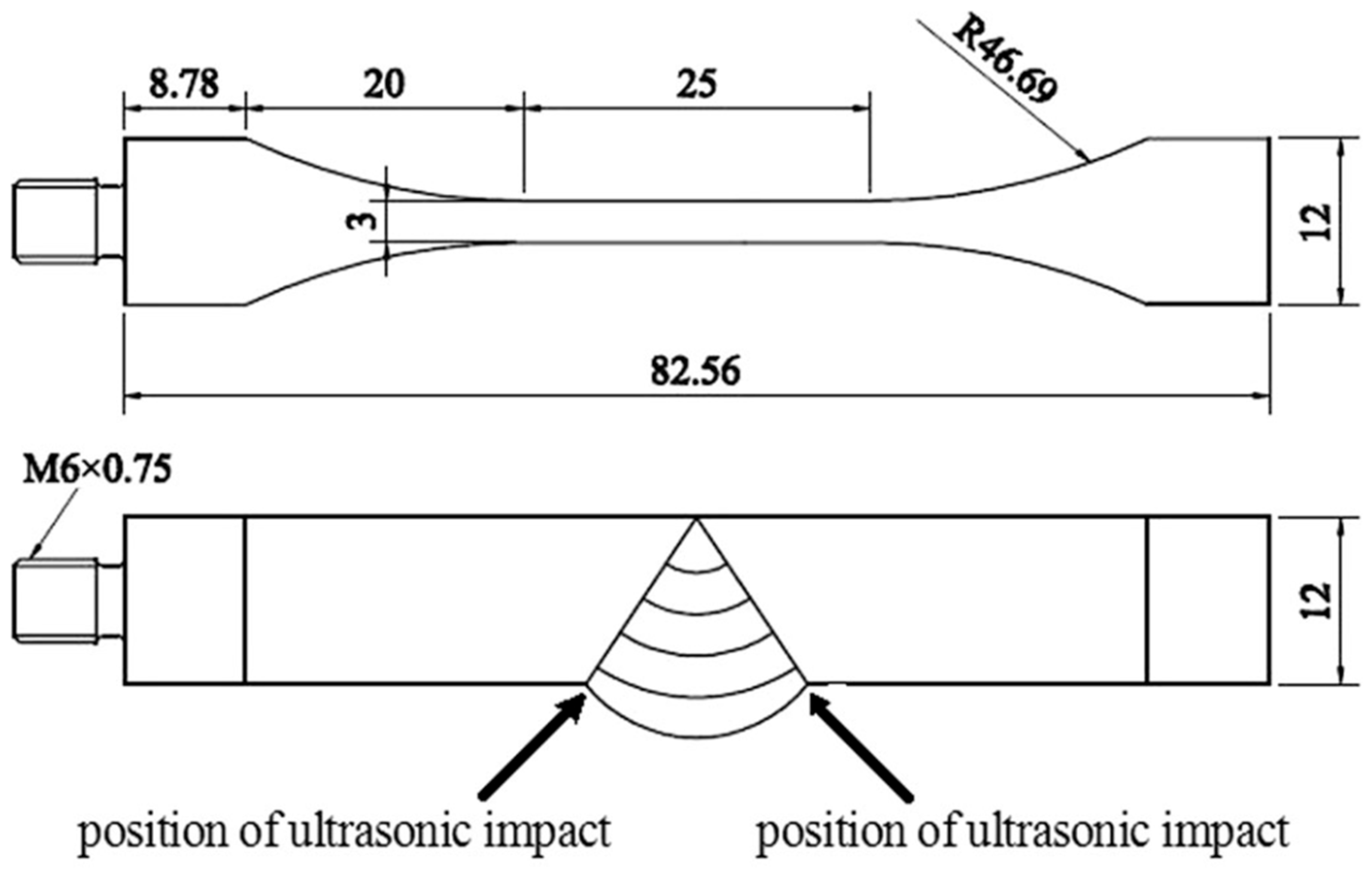
He et al. [57] studied the VHCF behaviour of GMAW butt joints of SMA490BW, a weathering steel alloy, before and after UPT. A specially designed specimen was employed with the weld toe in the region of highest stress (Figure 13). Both as-welded joints and joints subjected to UPT each showed multiple failures in the VHCF regime, with all fractures originating from the weld toe. UPT resulted in a 38% increase in fatigue strength at 109 cycles [57].
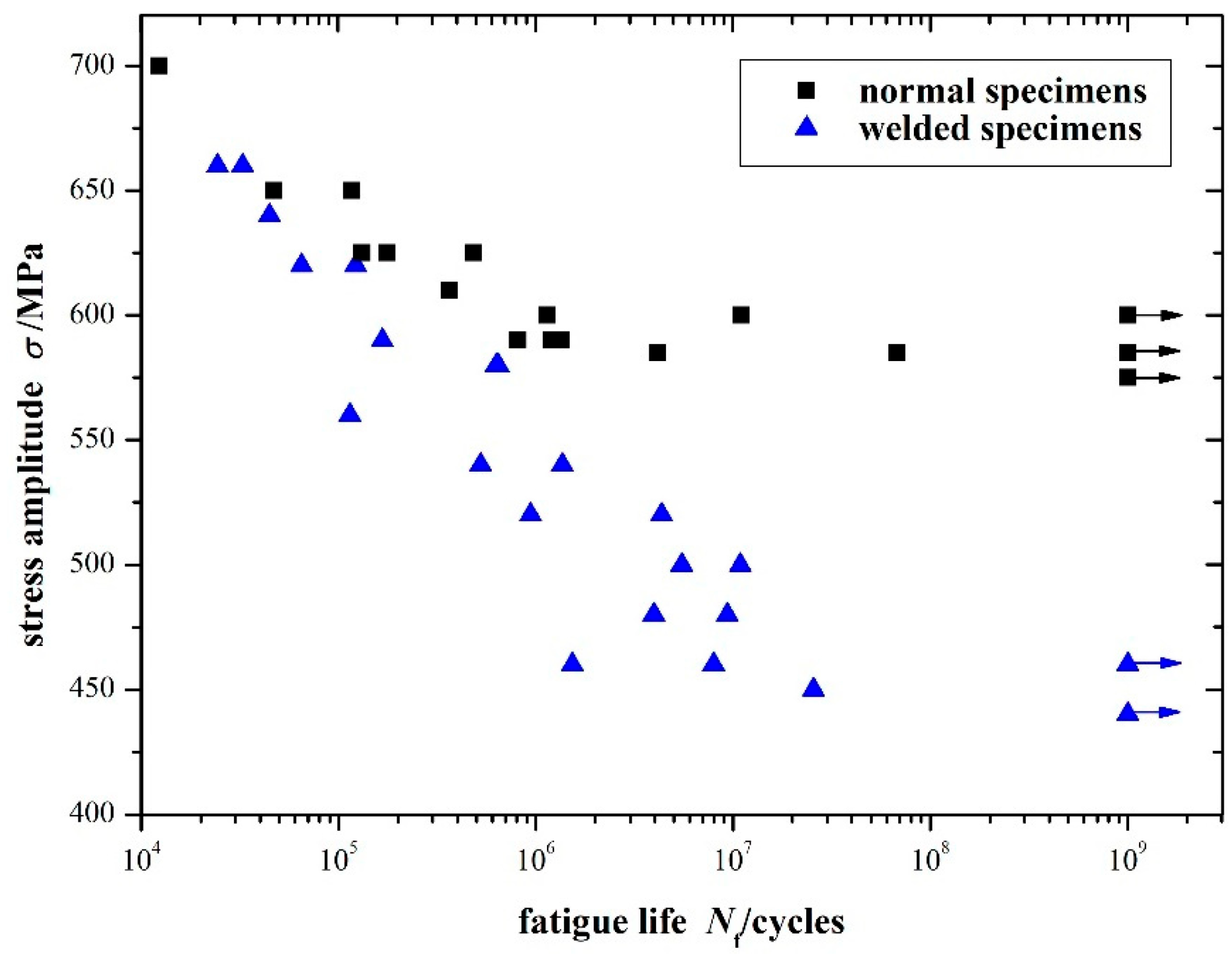
The VHCF properties of SAW joints made of KMN-I, a low-alloy steel used for compressor blades, were investigated by Wang et al. [58]. The standard cylindrical hourglass shape was used for both base metal specimens and specimens with the FZ located in the centre. The fatigue strength of welds was similar to the base metal at lower fatigue lives (104–105 cycles), but the S–N curve for welds decreased at a greater rate (Figure 14). All fatigue failures of welds occurred below 3 × 10⁷ cycles, indicating a possible fatigue limit early in the VHCF regime [58].
In a series of papers [59,60,61], the fatigue properties of alloy steel welds at elevated temperatures were investigated up to 5 × 10⁷ cycles using a loading frequency of 100 Hz. Failures occurred from internal inclusions above 107 cycles for SAW joints of a CrMoV steel tested at 370 °C [59]. No fatigue limit was observed for dissimilar SAW joints of CrMoV and 9% Cr steels at 500 °C [60]. Specimens predominantly failed at the HAZ of the weaker CrMoV steel, initiating from inclusions or microstructural inhomogeneities [60]. Li et al. [61] tested two different specimen types of SAW joints of 25Cr2Ni2MoV steel at 300 °C. Specimens with the HAZ in the centre had an approx. 7% greater fatigue strength than specimens with the FZ in the centre, an effect attributed to increased dynamic strain ageing [61].
Table 2 displays a summary of the research on the VHCF properties of alloy steel welds. Failures in the VHCF regime were observed for all welded joints of alloy steels; therefore, the assumption of a fatigue limit before 107 cycles is non-conservative. In addition, this alloy class has been used to investigate the frequency and size effects of UFT.

3.3. Stainless Steels

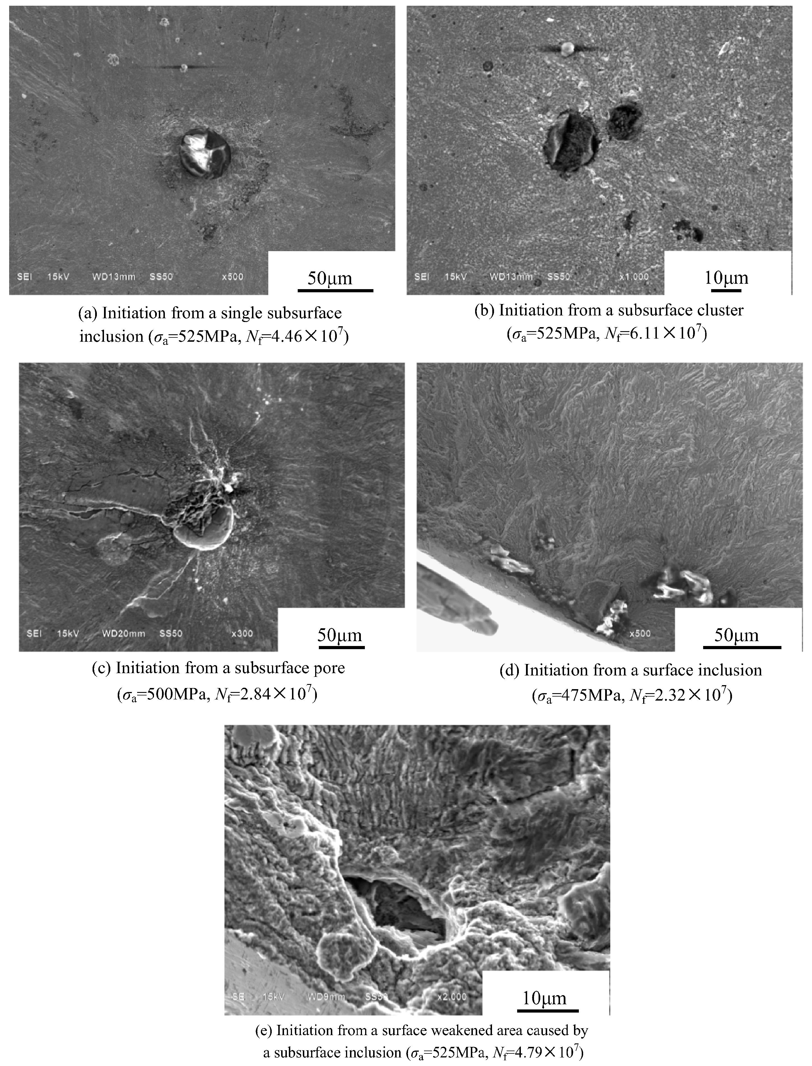
The use of welded joints of stainless steel alloys in applications such as impeller blades [62] and nuclear reactor coolant pipes [63] means that they are subjected to VHCF during service; however, there is only limited research for this class of materials. The VHCF behaviour of SMAW joints of FV520B-I martensitic stainless steel was investigated by Zhang et al. [62]. Their study represents the only published research on the effect of surface roughness on the VHCF of welds, with “smooth” (Ra ≈ 0.05) and “rough” (Ra ≈ 0.6) cylindrical hourglass-shaped specimens tested at 20 kHz. The smooth specimens displayed the typical VHCF behaviour of high-strength steels [64], with no fatigue limit and some fractures originating from subsurface non-metallic inclusions or pores (Figure 15a–c). Energy-dispersive spectroscopy revealed the inclusions originated from the flux coating of the welding electrode. Additionally, two smooth specimens fractured from inclusions located at the specimen surface (Figure 15d,e). The rough specimens exhibited a tendency to fail in the HCF regime from surface initiation sites, while only two internally initiated failures in the VHCF were recorded [62]. In a subsequent paper using the same base metal and weld method, the size effect was assessed using smooth specimens [65]. Cylindrical dog-bone-shaped specimens with an approx. 3.3x greater risk volume showed a slight decrease in VHCF strength but no change in crack initiation behaviour. Compared to base metal, both specimen shapes showed a lower fatigue life and greater scatter in fatigue testing results [65].
Xiong et al. [63,66] investigated the VHCF behaviour of GTAW and laser beam welding (LBW) joints of 316L stainless steel using cylindrical dog-bone-shaped specimens. GTAW joints presented no fatigue limit in the VHCF regime, and specimens tended to fail from surface-initiated cracks. The GTAW joints showed comparable fatigue strength with the base metal when stress amplitudes were normalised to the ultimate tensile strength of each region [66]. Despite the presence of large pores, the refined microstructure due to the high heat input of the LBW process resulted in comparable VHCF strength to GTAW joints [63]. A greater scatter was displayed in the fatigue lives of LBW specimens due to the random size distribution of pores [63].
No definitive conclusions can be drawn from the limited research on the VHCF properties of stainless steel welds (Table 3). The comparison of welding methods, as investigated by Xiong et al. [63], is not seen in research on other metals and could be important for the design of components and structures subjected to VHCF. Future research should focus on expanding the data for this class of materials, with attention to other base metals and welding methods.

3.4. Non-Ferrous Alloys

There is limited fatigue data within the engineering literature for welded joints of non-ferrous alloys in the VHCF domain, with only a small number of investigations conducted focusing on aluminium [67,68,69], magnesium [70], and titanium alloys [71,72,73,74]. The VHCF behaviour of GMAW joints of AA6082 was characterised by Cremer et al. [67] using rectangular dog-bone-shaped specimens with the weld reinforcement removed. Three different specimens were used, each featuring either the base metal, HAZ, or FZ at the position of maximum stress. Neither of the weld zones showed a fatigue limit below 2 × 10⁹ cycles. As expected, the base metal exhibited the greatest fatigue strength, while the HAZ presented a slightly inferior strength (reduced by approx. 10%). Due to incomplete fusion and gas pore defects, the lowest fatigue strength was identified in the FZ specimens, with significant scatter in the results. Notched specimens were also tested in different heat-treated conditions, to achieve hardness values representative of the FZ (85 HV) and HAZ (75 HV). The notch factor was chosen to represent the stress concentration at the weld toe. It was reported that the VHCF strength of the notched specimens decreased as the material hardness decreased [67]. One limitation of this research is that although the heat-treated notched specimens allowed for a simulated fatigue test of the weld toe, they did not include defects, such as micro-ripples, spatter droplets, small undercuts, or microscopic slag inclusions [75,76], that can be detrimental to fatigue strength.
Deng et al. [68] examined the VHCF behaviour of AA7050 base metal and friction stir-welded (FSW) butt joints using cylindrical dog-bone-shaped specimens. No fatigue limit was observed for either specimen type up to 109 cycles. The welded specimens showed slightly greater fatigue strength than the base metal [68]. The findings were consistent with the literature on the HCF of FSW joints, with the highly refined microstructures caused by the FSW process considerably enhancing fatigue performance [77]. No fatigue limit was found for FSW joints of AA6061 below 109 cycles by He et al. [69]. Rectangular dog-bone-shaped specimens were extracted from different regions through the thickness of the weld; it was found that specimens extracted from the weld root displayed the lowest fatigue life due to the softening that occurred in this region during the FSW process [69]. The VHCF behaviour of FSW joints of ZK60 magnesium alloy was investigated by Chen et al. [70] using rectangular dog-bone-shaped specimens. The fatigue strength of the joints was found to continually decrease in the VHCF regime, with no discernible fatigue limit. All failures above 106 cycles were identified to originate from porosity defects in the thermo-mechanically affected zone [70].
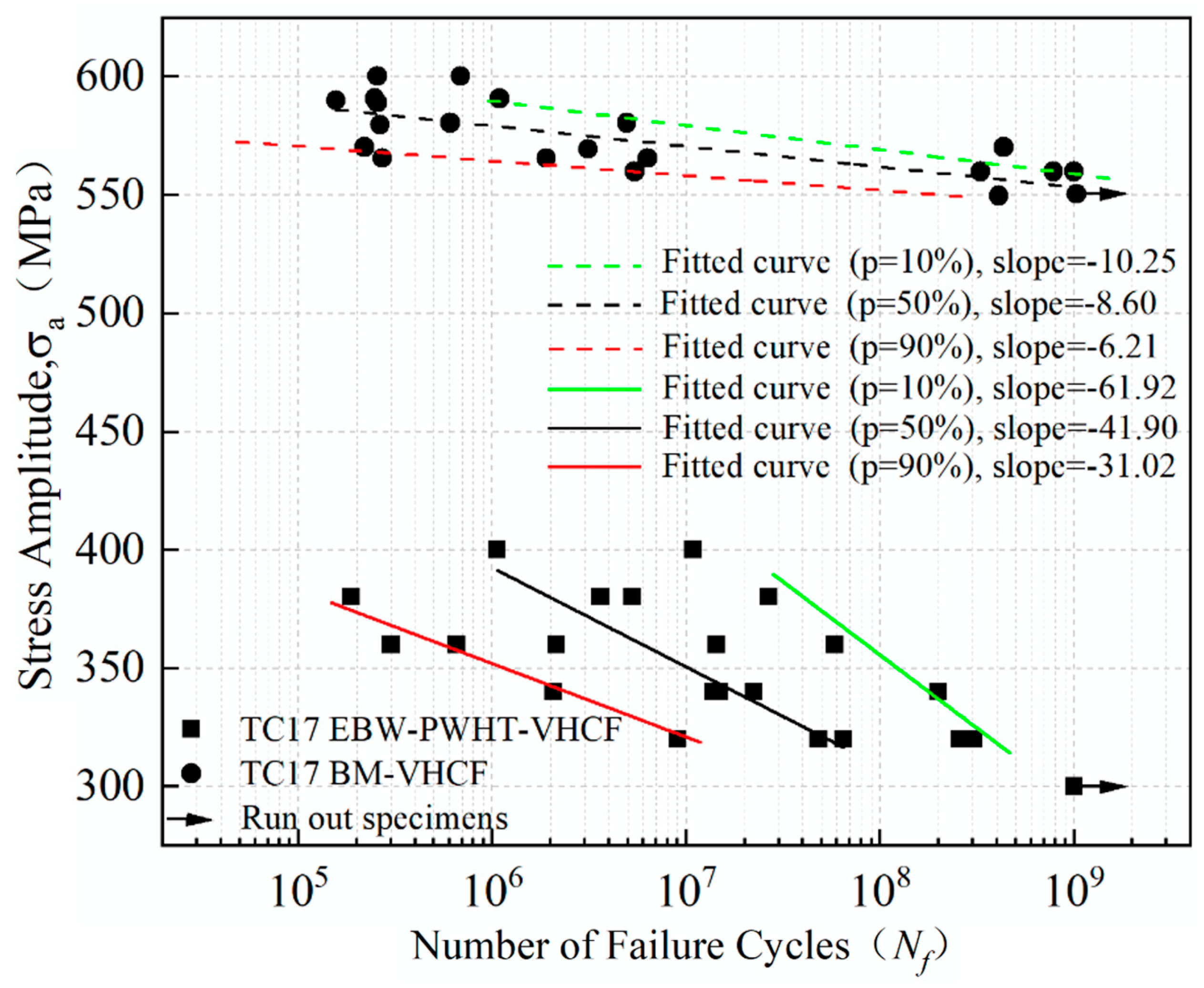
Electron beam welding (EBW) joints of titanium alloys have received some research attention [71,72,73,74] due to their use in aerospace engines, which are subjected to VHCF in service. Liu et al. [71] investigated the VHCF behaviour of TC17 titanium alloy EBW joints. Cylindrical dog-bone-shaped specimens were employed, and welds were tested after PWHT. Both EBW and base metal specimens showed no fatigue limit prior to 109 cycles at room temperature. The fatigue strength of EBW joints was pronouncedly decreased compared to the base metal; a reduction of approx. 45% was found in the VHCF regime (Figure 16). The large scatter in the fatigue lives of welded joints was ascribed to the random size distribution of pores and the location of pores relative to the specimen surface [71]. In two subsequent studies [72,73], identical EBW TC17 joints were tested at 400 °C. The S–N curve at this elevated temperature revealed a reduced slope in the VHCF regime, although no fatigue limit was found. At 400 °C, the fatigue strength showed a reduction of approx. 20% at 109 cycles as compared to room temperature. Pore-initiated cracks were still the predominant mode of failure [72,73]. Zheng et al. [74] found no fatigue limit for TC21 titanium alloy EBW joints and a similar dependence of the VHCF behaviour on pores.
A synopsis of the research carried out to date on the VHCF properties of welded joints of non-ferrous alloys is shown in Table 4. In general, non-ferrous alloy welds presented a similar trend to ferrous alloys, with no fatigue limit observed in the VHCF regime. The VHCF properties developed by more advanced welding methods (FSW and EBW) are investigated more commonly for this class of metals compared to ferrous alloys. Titanium alloys can be joined by a range of conventional welding methods, e.g., GMAW and GTAW [78]; therefore, there is significant merit in considering the VHCF of welds produced by these processes in future research endeavours.

4. Design Standards and Industrial Case Studies

4.1. Design Standards for Very High Cycle Fatigue of Welds

The guidance for the design of welded joints subjected to VHCF varies between international standards. Within these standards, S–N curves are generally specified in terms of the nominal stress. This refers to the stress remote of the weld bead, with no consideration of the stress concentration caused by the weld toe geometry [79,80]. Diverse welded joint geometries are then assigned to a certain fatigue class corresponding to their fatigue strength. For example, a full penetration butt weld ground flush is assigned a higher fatigue class than a partial penetration butt weld.
One of the main differences is whether a fatigue limit is incorporated into the design S–N curves. BS 7608:2014 [80] assumes a fatigue limit of 1 × 10⁷ cycles for normal stresses in the absence of corrosion. The fatigue limit in AWS D1.1/D1.1M:2020 [81] is defined in the range of 2 × 10⁶ and 2 × 10⁷ cycles, depending on the fatigue class of the welded joint. A decrease in the slope of the S–N curves in the VHCF regime is considered in a number of standards [79,82,83]. This is similar to the observations reported by some researchers in laboratory-based VHCF tests [41,43]. Due to the emergence of VHCF as a separate research field, the IIW removed the consideration of a fatigue limit in the 2006 update of their design recommendations [79,84]. In line with this update, the slope of the S–N curves is reduced at 1 × 10⁷ cycles, so that the rate of decrease in fatigue strength is 10% per decade of loading cycles [79]. BS EN 1993-1-9:2005 [82] specifies a reduction in the slope of the S–N curve between 5 × 10⁶ and 1 × 10⁸ cycles, with a fatigue limit beyond this. For offshore applications in clean air (i.e., no influence of corrosion), DNV-RP-C203 [83] defines a reduction in the slope at 1 × 10⁷ cycles with no fatigue limit. It is evident that there is no consensus in the relevant standards on the fatigue assessment of welded joints in the VHCF domain. The consideration of a fatigue limit could potentially lead to the non-conservative design of structures and the standards that consider this should be updated.

4.2. Industrial Case Studies

Studying failures of welded components subjected to VHCF in an industrial setting allows for further insight into the topic, in the absence of the limitations of the UFT method. Fry [14] gathered data on fatigue failures of welded components of vibrating screens used in the mineral processing industry. Vibrating screens typically operate continually between 14 and 17 Hz; therefore, the VHCF domain is reached within a month of usage [14]. Due to the common occurrence of fatigue failures beyond 107 cycles, an extension to the design S–N curves used within BS7608:2014 [80] was proposed (Figure 17). The extension of the S–N curves involves a change in slope at 107 cycles and a fatigue limit at 4 × 10⁸ cycles for welds protected from corrosion [14].
More recently, the failure of a welded joint after 6.2 × 10⁷ cycles on a drive beam of a vibrating screen was investigated by Rumiche et al. [85]. Comparing the fatigue life of the component to an appropriate fatigue class from Fry’s modified S–N curves [14] returns an approximate stress range of 20 MPa, which is within typical operating stress ranges for vibrating screen components [85]. Other industrial applications where VHCF failures of welded components have been observed include conveyor pulleys [86] and railway bridges [87].
The VHCF behaviour of welds is an important consideration in the context of the service life extension of existing components. As an illustration, welded wind turbine monopiles approaching 20 years in service are being considered for further use after their initial design life [88]. Service life extension of existing welded components would result in both environmental and economic benefits [88].

5. Future Directions

As highlighted in this paper, research on the VHCF behaviour of various metals and weld methods has been conducted, but there are a number of knowledge gaps to be addressed in future research. Investigation of the fundamental challenges of the UFT method is required to promote a better understanding of the VHCF performance of welds. The frequency effect of welded joints has only been studied in one investigation, despite being identified as one of the primary limitations of UFT [27]. As the frequency effect is heavily dependent on crystalline structure [27], research is required for diverse metals, e.g., aluminium and titanium alloys. Unalloyed low-carbon steels show a significant frequency effect [31], yet there is no research comparing the results of conventional fatigue testing and UFT for welds of this class of material. The control of specimen surface temperature generally requires the combination of air or water cooling, and intermittent driving so the effect of these should be considered more often in relevant studies. A wide range of specimen geometries for UFT of welded joints have been exhibited in the literature, limiting comparisons that can be made between different investigations. The standardisation of specimen design for UFT of welded joints would allow for the VHCF behaviour of various base metals and welding methods to be suitably compared.
UFT machines require the use of specimens that are significantly smaller than welded joints in real components, and the limitation of this is often not considered. The local geometry of welded components causes stress concentration regions [5], and although some as-welded UFT specimen designs have been exhibited, this area needs further investigation. All studies described herein used uniaxial tensile-compressive loading in the VHCF regime. Therefore, the effect of various loading conditions, namely bending, torsional, and multiaxial loading, should be explored for welded joints using UFT. Applying mean stress is recommended when fatigue testing specimens of welded joints to represent the effect of residual stresses [79], but this has not been investigated to date. Additionally, the effect of corrosion on VHCF strength has not been thoroughly examined for welded joints. Fundamental studies on the effects of different weld methods and PWHT would also enhance the scientific understanding of this subject area.

6. Conclusions

UFT has been proven to be a viable method to study the VHCF of welded joints in a reasonable timeframe. The elevated loading frequency significantly accelerates testing; hence, the VHCF of welds can be investigated in a controlled laboratory environment rather than relying on reported failures of real-world components. Several conclusions can be drawn from the present review of the engineering literature on the VHCF behaviour of welds:
  • The VHCF strength of welded joints is generally lower than that of base metals, even when the stress concentration of the weld toe is removed by machining.
  • A continuous decrease in the S–N curve is observed beyond 107 loading cycles for all metallic welds studied to date (steel, aluminium, titanium, and magnesium alloys), challenging the classical assumption of a fatigue limit. This is further demonstrated by examples of in-service failures of welded components in the VHCF regime in various applications.
  • A change in the design S–N curves of standards that include a fatigue limit, e.g., BS7608:2014, should be implemented to guarantee the structural integrity of welded components operating in the VHCF regime.
  • The primary factor for the reduction in VHCF strength of welds is welding defects, principally inclusions and gas pores. Failures in the VHCF domain typically originate from these defects.
  • Limited research on UPT has shown the process to significantly increase the VHCF strength of welded joints due to the grain refinement and compressive residual stresses caused by the process.
  • Testing programmes that cover the HCF and VHCF regimes tend to show that there is a reduction in the slope of the S–N curve in the VHCF regime, an observation that has been reflected in some design standards.
Although the scientific understanding of the VHCF behaviour of welds has been greatly expanded in the past 20 years, the research field remains relatively unexplored; thus, more fundamental studies are required.

Author Contributions

Conceptualization, A.E., A.T. and Y.G.; investigation, A.E.; writing—original draft preparation, A.E.; writing—review and editing, A.T. and Y.G.; supervision, A.T. and Y.G. All authors have read and agreed to the published version of the manuscript.

Funding

This research received no external funding.

Data Availability Statement

No new data were created or analysed in this study. Data sharing is not applicable to this article.

Conflicts of Interest

The authors declare no conflict of interest.

References

  1. Campbell, F.C. Fatigue and Fracture—Understanding the Basics; ASM International: Materials Park, OH, USA, 2012; ISBN 978-1-61503-976-0. [Google Scholar]
  2. Masoudi Nejad, R.; Shariati, M.; Farhangdoost, K. Prediction of Fatigue Crack Propagation and Fractography of Rail Steel. Theor. Appl. Fract. Mech. 2019, 101, 320–331. [Google Scholar] [CrossRef]
  3. Moore, P.; Booth, G. The Welding Engineer’s Guide to Fracture and Fatigue; Elsevier: Amsterdam, The Netherlands, 2015; ISBN 9781782423706. [Google Scholar]
  4. Tsutsumi, S.; Fincato, R.; Luo, P.; Sano, M.; Umeda, T.; Kinoshita, T.; Tagawa, T. Effects of Weld Geometry and HAZ Property on Low-Cycle Fatigue Behavior of Welded Joint. Int. J. Fatigue 2022, 156, 106683. [Google Scholar] [CrossRef]
  5. Ma, M.; Lai, R.; Qin, J.; Wang, B.; Liu, H.; Yi, D. Effect of Weld Reinforcement on Tensile and Fatigue Properties of 5083 Aluminum Metal Inert Gas (MIG) Welded Joint: Experiments and Numerical Simulations. Int. J. Fatigue 2021, 144, 106046. [Google Scholar] [CrossRef]
  6. Zhan, R.; Wang, D.; Ren, Z.; Deng, C.; Xu, X.; Liang, H. Evolution of Welding Residual Stresses Involving the Cutting Process and Its Effect on Fatigue Performance. Int. J. Press. Vessel. Pip. 2022, 197, 104636. [Google Scholar] [CrossRef]
  7. Zerbst, U.; Ainsworth, R.A.; Beier, H.T.; Pisarski, H.; Zhang, Z.L.; Nikbin, K.; Nitschke-Pagel, T.; Münstermann, S.; Kucharczyk, P.; Klingbeil, D. Review on Fracture and Crack Propagation in Weldments—A Fracture Mechanics Perspective. Eng. Fract. Mech. 2014, 132, 200–276. [Google Scholar] [CrossRef]
  8. Sharma, A.; Oh, M.C.; Ahn, B. Recent Advances in Very High Cycle Fatigue Behavior of Metals and Alloys—A Review. Metals 2020, 10, 1200. [Google Scholar] [CrossRef]
  9. Pineau, A. Low-Cycle Fatigue. In Fatigue of Materials and Structures—Fundamentals; John Wiley & Sons: Hoboken, NJ, USA, 2010; pp. 113–177. ISBN 9781118623435. [Google Scholar]
  10. Bathias, C.; Drouillac, L.; Le François, P. How and Why the Fatigue S-N Curve Does Not Approach a Horizontal Asymptote. Int. J. Fatigue 2001, 23, 143–151. [Google Scholar] [CrossRef]
  11. Bathias, C. There Is No Infinite Fatigue Life in Metallic Materials. Fatigue Fract. Eng. Mater. Struct. 1999, 22, 559–565. [Google Scholar] [CrossRef]
  12. He, C.; Liu, Y.; Fang, D.; Wang, Q. Very High Cycle Fatigue Behavior of Bridge Steel Welded Joint. Theor. Appl. Mech. Lett. 2012, 2, 31010. [Google Scholar] [CrossRef]
  13. Yeom, H.; Choi, B.; Seol, T.; Lee, M.; Jeon, Y. Very High Cycle Fatigue of Butt-Welded High-Strength Steel Plate. Metals 2017, 7, 103. [Google Scholar] [CrossRef]
  14. Fry, P.R. High Cycle Fatigue of Welded Structures: Design Guidelines Validated by Case Studies. Eng. Fail. Anal. 2014, 46, 179–187. [Google Scholar] [CrossRef]
  15. Yin, D.; Wang, D.; Jing, H.; Huo, L. The Effects of Ultrasonic Peening Treatment on the Ultra-Long Life Fatigue Behavior of Welded Joints. Mater. Des. 2010, 31, 3299–3307. [Google Scholar] [CrossRef]
  16. Mayer, H. Recent Developments in Ultrasonic Fatigue. Fatigue Fract. Eng. Mater. Struct. 2016, 39, 3–29. [Google Scholar] [CrossRef]
  17. Kuhn, H.; Medlin, D. Ultrasonic Fatigue Testing. In Mechanical Testing and Evaluation; ASM International: Materials Park, OH, USA, 2000; Volume 8, pp. 717–729. ISBN 978-1-62708-176-4. [Google Scholar]
  18. Trško, L.; Nový, F.; Bokůvka, O.; Jambor, M. Ultrasonic Fatigue Testing in the Tension-Compression Mode. J. Vis. Exp. 2018, 2018, 57007. [Google Scholar] [CrossRef]
  19. Wan, J.; Zhao, J.; Zhou, L.; Zhang, S.; Zhao, H. A Novel Methodology for Bending Ultrasonic Fatigue Testing in the VHCF Regime. Int. J. Fatigue 2023, 170, 107562. [Google Scholar] [CrossRef]
  20. Marines-Garcia, I.; Doucet, J.P.; Bathias, C. Development of a New Device to Perform Torsional Ultrasonic Fatigue Testing. Int. J. Fatigue 2007, 29, 2094–2101. [Google Scholar] [CrossRef]
  21. da Costa, P.R.; Soares, H.; Reis, L.; Freitas, M. Ultrasonic Fatigue Testing under Multiaxial Loading on a Railway Steel. Int. J. Fatigue 2020, 136, 105581. [Google Scholar] [CrossRef]
  22. Shimadzu Corporation. USF-2000A Hardware Instruction Manual. Shimadzu Corporation, 2017. Available online: https://www.shimadzu.com/an/sites/shimadzu.com.an/files/pim/pim_document_file/manuals/13951/349-04408.pdf (accessed on 20 September 2023).
  23. Feng, N.; Wang, X.; Guo, J.; Li, Q.; Yu, J.; Zhang, X. Design Theory and Experimental Research of Ultrasonic Fatigue Test. Machines 2022, 10, 635. [Google Scholar] [CrossRef]
  24. The Japan Welding Engineering Society. Method for Ultrasonic Fatigue Testing in Metallic Material; WES 1112: Tokyo, Japan, 2022. [Google Scholar]
  25. Furuya, Y.; Shimamura, Y.; Takanashi, M.; Ogawa, T. Standardization of an Ultrasonic Fatigue Testing Method in Japan. Fatigue Fract. Eng. Mater. Struct. 2022, 45, 2415–2420. [Google Scholar] [CrossRef]
  26. Bach, J.; Göken, M.; Höppel, H.-W. Fatigue of Low Alloyed Carbon Steels in the HCF/VHCF-Regimes. In Fatigue of Materials at Very High Numbers of Loading Cycles; Chris, H.J., Ed.; Springer Spektrum: Berlin/Heidelberg, Germany, 2018; pp. 1–23. ISBN 978-3-658-24531-3. [Google Scholar]
  27. Hong, Y.; Hu, Y.; Zhao, A. Effects of Loading Frequency on Fatigue Behavior of Metallic Materials—A Literature Review. Fatigue Fract. Eng. Mater. Struct. 2023, 46, 3077–3098. [Google Scholar] [CrossRef]
  28. Guennec, B.; Ueno, A.; Sakai, T.; Takanashi, M.; Itabashi, Y.; Ota, M. Dislocation-Based Interpretation on the Effect of the Loading Frequency on the Fatigue Properties of JIS S15C Low Carbon Steel. Int. J. Fatigue 2015, 70, 328–341. [Google Scholar] [CrossRef]
  29. Milne, L.; Gorash, Y.; Comlekci, T.; MacKenzie, D. Frequency Effects in Ultrasonic Fatigue Testing (UFT) of Q355B Structural Steel. Procedia Struct. Integr. 2022, 42, 623–630. [Google Scholar] [CrossRef]
  30. Gorash, Y.; Comlekci, T.; Styger, G.; Kelly, J.; Brownlie, F.; Milne, L. Ultrasonic Fatigue Testing of Structural Steel S275JR+AR with Insights into Corrosion, Mean Stress and Frequency Effects. Materials 2023, 16, 1799. [Google Scholar] [CrossRef]
  31. Guennec, B.; Kinoshita, T.; Horikawa, N.; Oguma, N.; Sakai, T. Loading Frequency Effect on the Fatigue Endurance of Structural Carbon Steels: Estimation Based on Dislocation Motion Theory and Experimental Verification of the Model. Int. J. Fatigue 2023, 172, 107634. [Google Scholar] [CrossRef]
  32. Zhao, A.; Xie, J.; Sun, C.; Lei, Z.; Hong, Y. Effects of Strength Level and Loading Frequency on Very-High-Cycle Fatigue Behavior for a Bearing Steel. Int. J. Fatigue 2012, 38, 46–56. [Google Scholar] [CrossRef]
  33. Mughrabi, H. Specific Features and Mechanisms of Fatigue in the Ultrahigh-Cycle Regime. Int. J. Fatigue 2006, 28, 1501–1508. [Google Scholar] [CrossRef]
  34. Pyttel, B.; Schwerdt, D.; Berger, C. Very High Cycle Fatigue—Is There a Fatigue Limit? Int. J. Fatigue 2011, 33, 49–58. [Google Scholar] [CrossRef]
  35. Lee, J.; Park, S.Y.; Choi, B.H. Evaluation of Fatigue Characteristics of Aluminum Alloys and Mechanical Components Using Extreme Value Statistics and C-Specimens. Metals 2021, 11, 1915. [Google Scholar] [CrossRef]
  36. Murakami, Y.; Nomoto, T.; Ueda, T. Factors Influencing the Mechanism of Superlong Fatigue Failure in Steels. Fatigue Fract. Eng. Mater. Struct. 1999, 22, 581–590. [Google Scholar] [CrossRef]
  37. Sakai, T.; Sato, Y.; Oguma, N. Characteristics S-N Properties of High-Carbon-Chromium-Bearing Steel under Axial Loading in Long-Life Fatigue. Fatigue Fract. Eng. Mater. Struct. 2002, 25, 765–773. [Google Scholar] [CrossRef]
  38. De Li, Y.; Zhang, L.L.; Fei, Y.H.; Liu, X.Y.; Li, M.X. On the Formation Mechanisms of Fine Granular Area (FGA) on the Fracture Surface for High Strength Steels in the VHCF Regime. Int. J. Fatigue 2016, 82, 402–410. [Google Scholar] [CrossRef]
  39. Sippel, J.P.; Kerscher, E. Properties of the Fine Granular Area and Postulated Models for Its Formation during Very High Cycle Fatigue—A Review. Appl. Sci. 2020, 10, 8475. [Google Scholar] [CrossRef]
  40. Chen, Z.; Dong, Z.; Liu, C.; Dai, Y.; He, C. Characterization on Crack Initiation and Early Propagation Region of Nickel-Based Alloys in Very High Cycle Fatigue. Materials 2022, 15, 5806. [Google Scholar] [CrossRef] [PubMed]
  41. Zhao, X.; Dongpo, W.; Deng, C.; Liu, Y.; Zongxian, S. The Fatigue Behaviors of Butt Welds Ground Flush in the Super-Long Life Regime. Int. J. Fatigue 2012, 36, 1–8. [Google Scholar] [CrossRef]
  42. Tridello, A.; Boursier Niutta, C.; Berto, F.; Tedesco, M.M.; Plano, S.; Gabellone, D.; Paolino, D.S. Design against Fatigue Failures: Lower Bound P-S-N Curves Estimation and Influence of Runout Data. Int. J. Fatigue 2022, 162, 106934. [Google Scholar] [CrossRef]
  43. Liu, Y.; He, C.; Huang, C.; Khan, M.K.; Wang, Q. Very Long Life Fatigue Behaviors of 16Mn Steel and Welded Joint. Struct. Eng. Mech. 2014, 52, 889–901. [Google Scholar] [CrossRef]
  44. He, C.; Huang, C.; Liu, Y.; Wang, Q. Fatigue Damage Evaluation of Low-Alloy Steel Welded Joints in Fusion Zone and Heat Affected Zone Based on Frequency Response Changes in Gigacycle Fatigue. Int. J. Fatigue 2014, 61, 297–303. [Google Scholar] [CrossRef]
  45. Shang, D.G. Measurement of Fatigue Damage Based on the Natural Frequency for Spot-Welded Joints. Mater. Des. 2009, 30, 1008–1013. [Google Scholar] [CrossRef]
  46. Jonsson, B.; Dobmann, G.; Hobbacher, A.F.; Kassner, M.; Marquis, G. IIW Guidelines on Weld Quality in Relationship to Fatigue Strength; Springer International Publishing: Cham, Switzerland, 2016; ISBN 978-3-319-19197-3. [Google Scholar]
  47. Nishikawa, H.; Furuya, Y. Gigacycle Fatigue Fracture of Low Strength Carbon Steel, Tested Using a Simulated Heat Affected Zone Microstructure. ISIJ Int. 2019, 59, 1926–1928. [Google Scholar] [CrossRef]
  48. Schaumann, P.; Steppeler, S. Fatigue Tests of Axially Loaded Butt Welds up to Very High Cycles. Procedia Eng. 2013, 66, 88–97. [Google Scholar] [CrossRef]
  49. Invernizzi, S.; Montagnoli, F.; Carpinteri, A. Experimental Evidence of Specimen-Size Effects on EN-AW6082 Aluminum Alloy in VHCF Regime. Appl. Sci. 2021, 11, 4272. [Google Scholar] [CrossRef]
  50. Gao, Z.; Wang, D.; Gong, B.; Deng, C.; Wu, S.; Zhang, H. VHCF Behavior of Welded Joints with HFMI Treatment under Moisture Conditions. Weld. J. 2022, 101, 27–42. [Google Scholar] [CrossRef]
  51. Oyyaravelu, R.; Kuppan, P.; Arivazhagan, N. Metallurgical and Mechanical Properties of Laser Welded High Strength Low Alloy Steel. J. Adv. Res. 2016, 7, 463–472. [Google Scholar] [CrossRef] [PubMed]
  52. Kou, S. Welding Metallurgy, 2nd ed.; John Wiley & Sons: Hoboken, NJ, USA, 2003; ISBN 3175723993. [Google Scholar]
  53. Zhu, M.L.; Liu, L.L.; Xuan, F.Z. Effect of Frequency on Very High Cycle Fatigue Behavior of a Low Strength Cr-Ni-Mo-V Steel Welded Joint. Int. J. Fatigue 2015, 77, 166–173. [Google Scholar] [CrossRef]
  54. Murakami, Y. Metal Fatigue: Effects of Small Defects and Nonmetallic Inclusions, 2nd ed.; Elsevier: New York, NY, USA, 2019; ISBN 9780128138779. [Google Scholar]
  55. Zhu, M.L.; Xuan, F.Z. Failure Mechanisms and Fatigue Strength Assessment of a Low Strength Cr−Ni−Mo−V Steel Welded Joint: Coupled Frequency and Size Effects. Mech. Mater. 2016, 100, 198–208. [Google Scholar] [CrossRef]
  56. Hu, J.-T.; Chen, R.; Zhu, G.; Wang, C.; Zhu, M.-L.; Xuan, F.-Z. Heat Dissipation Behavior of a Low-Strength-Steel Welded Joint in Ultrasonic Fatigue. Metals 2022, 12, 1857. [Google Scholar] [CrossRef]
  57. He, B.; Deng, H.; Jiang, M.; Wei, K.; Li, L. Effect of Ultrasonic Impact Treatment on the Ultra High Cycle Fatigue Properties of SMA490BW Steel Welded Joints. Int. J. Adv. Manuf. Technol. 2018, 96, 1571–1577. [Google Scholar] [CrossRef]
  58. Wang, P.; Wang, W.; Zhang, M.; Zhou, Q.; Gao, Z. Effects of Specimen Size and Welded Joints on the Very High Cycle Fatigue Properties of Compressor Blade Steel KMN-I. Coatings 2021, 11, 1244. [Google Scholar] [CrossRef]
  59. Zhu, M.L.; Xuan, F.Z.; Du, Y.N.; Tu, S.T. Very High Cycle Fatigue Behavior of a Low Strength Welded Joint at Moderate Temperature. Int. J. Fatigue 2012, 40, 74–83. [Google Scholar] [CrossRef]
  60. Zhang, W.C.; Zhu, M.L.; Wang, K.; Xuan, F.Z. Failure Mechanisms and Design of Dissimilar Welds of 9%Cr and CrMoV Steels up to Very High Cycle Fatigue Regime. Int. J. Fatigue 2018, 113, 367–376. [Google Scholar] [CrossRef]
  61. Li, S.C.; Zhang, W.C.; Zhu, M.L.; Xuan, F.Z. On Specimen Design for High Cycle Fatigue Testing of Welded Joint. Int. J. Fatigue 2020, 136, 105597. [Google Scholar] [CrossRef]
  62. Zhang, M.; Wang, W.; Wang, P.; Liu, Y.; Li, J. Fatigue Behavior and Mechanism of FV520B-I Welding Seams in a Very High Cycle Regime. Int. J. Fatigue 2016, 87, 22–37. [Google Scholar] [CrossRef]
  63. Xiong, Z.; Peng, E.; Zeng, L.; Xu, Q. Giga-Cycle Fatigue Behavior of the Nuclear Structure of 316L Weldments. Front. Energy Res. 2021, 9, 696608. [Google Scholar] [CrossRef]
  64. Himmelbauer, F.; Winter, G.; Grün, F.; Kiesling, C. VHCF Properties and Assessment of Specimens and Thin-Walled Component-like Structures Made of High-Strength Steel X5CrNiCuNb16-4. Int. J. Fatigue 2022, 156, 106645. [Google Scholar] [CrossRef]
  65. Zhang, M.; Zhang, H.; Li, M.; Liu, L.; Wang, P. Fatigue Behavior and Mechanism of Dog-Bone-Shaped Specimens of FV520B-I in a Very High Cycle Regime. Fatigue Fract. Eng. Mater. Struct. 2022, 45, 3658–3676. [Google Scholar] [CrossRef]
  66. Xiong, Z.; Wei, D.; Wang, H.; Shi, H.J.; Ma, X. Fatigue Behavior of 316 L Stainless Steel Weldment up to Very-High-Cycle Fatigue Regime. Mater. Res. Express 2019, 6, 076514. [Google Scholar] [CrossRef]
  67. Cremer, M.; Zimmermann, M.; Christ, H.J. High-Frequency Cyclic Testing of Welded Aluminium Alloy Joints in the Region of Very High Cycle Fatigue (VHCF). Int. J. Fatigue 2013, 57, 120–130. [Google Scholar] [CrossRef]
  68. Deng, C.; Wang, H.; Gong, B.; Li, X.; Lei, Z. Effects of Microstructural Heterogeneity on Very High Cycle Fatigue Properties of 7050-T7451 Aluminum Alloy Friction Stir Butt Welds. Int. J. Fatigue 2016, 83, 100–108. [Google Scholar] [CrossRef]
  69. He, C.; Liu, Y.; Dong, J.; Wang, Q.; Wagner, D.; Bathias, C. Through Thickness Property Variations in Friction Stir Welded AA6061 Joint Fatigued in Very High Cycle Fatigue Regime. Int. J. Fatigue 2016, 82, 379–386. [Google Scholar] [CrossRef]
  70. Chen, Y.; He, C.; Yang, K.; Zhang, H.; Wang, C.; Wang, Q.; Liu, Y. Effects of Microstructural Inhomogeneities and Micro-Defects on Tensile and Very High Cycle Fatigue Behaviors of the Friction Stir Welded ZK60 Magnesium Alloy Joint. Int. J. Fatigue 2019, 122, 218–227. [Google Scholar] [CrossRef]
  71. Liu, F.; Zhang, H.; Liu, H.; Chen, Y.; Kashif, K.M.; Wang, Q.; Liu, Y. Influence of Welded Pores on Very Long-Life Fatigue Failure of the Electron Beam Welding Joint of TC17 Titanium Alloy. Materials 2019, 12, 1825. [Google Scholar] [CrossRef] [PubMed]
  72. Liu, F.; Chen, Y.; He, C.; Wang, C.; Li, L.; Liu, Y.; Wang, Q. Very Long Life Fatigue Failure Mechanism of Electron Beam Welded Joint for Titanium Alloy at Elevated Temperature. Int. J. Fatigue 2021, 152, 106446. [Google Scholar] [CrossRef]
  73. Liu, F.; Chen, Y.; Li, L.; Wang, C.; Wang, Q.; Liu, Y. Influence of Welded Pores on Fatigue Behavior of TC17 Titanium Alloy Welded Joints Subjected to Gigacycle Regime at Room and High Temperatures. J. Mater. Sci. Technol. 2023. [Google Scholar] [CrossRef]
  74. Zheng, Y.; Zhao, Z.; Zhang, Z.; Zong, W.; Dong, C. Internal Crack Initiation Characteristics and Early Growth Behaviors for Very-High-Cycle Fatigue of a Titanium Alloy Electron Beam Welded Joints. Mater. Sci. Eng. A 2017, 706, 311–318. [Google Scholar] [CrossRef]
  75. Matsuda, K.; Kodama, S. Observation of Fatigue Microcracks and Estimation of Fatigue Strength of a Thin Sheet Arc Welded Part Considering Micro-Ripples. Int. J. Fatigue 2021, 145, 106087. [Google Scholar] [CrossRef]
  76. Schork, B.; Kucharczyk, P.; Madia, M.; Zerbst, U.; Hensel, J.; Bernhard, J.; Tchuindjang, D.; Kaffenberger, M.; Oechsner, M. The Effect of the Local and Global Weld Geometry as Well as Material Defects on Crack Initiation and Fatigue Strength. Eng. Fract. Mech. 2018, 198, 103–122. [Google Scholar] [CrossRef]
  77. Toumpis, A.; Galloway, A.; Molter, L.; Polezhayeva, H. Systematic Investigation of the Fatigue Performance of a Friction Stir Welded Low Alloy Steel. Mater. Des. 2015, 80, 116–128. [Google Scholar] [CrossRef]
  78. Xing, S.; Dong, P. Fatigue of Titanium Weldments: S-N Testing and Analysis for Data Transferability among Different Joint Types. Mar. Struct. 2017, 53, 1–19. [Google Scholar] [CrossRef]
  79. Hobbacher, A.F. Recommendations for Fatigue Design of Welded Joints and Components; Springer International Publishing: Cham, Switzerland, 2016; ISBN 978-3-319-23756-5. [Google Scholar]
  80. BS 7608:2014; Guide to Fatigue Design and Assessment of Steel Products. British Standards Institution: London, UK, 2014.
  81. AWS D1.1/D1.1M:2020; Structural Welding Code—Steel. American Welding Society: Doral, FL, USA, 2020.
  82. BS EN 1993-1-9:2005; Eurocode 3: Design of Steel Structures—Fatigue. British Standards Institution: London, UK, 2005.
  83. DNV-RP-C203; Fatigue Design of Offshore Steel Structures. DNV: Høvik, Norway, 2019.
  84. Hobbacher, A.F. The New IIW Recommendations for Fatigue Assessment of Welded Joints and Components—A Comprehensive Code Recently Updated. Int. J. Fatigue 2009, 31, 50–58. [Google Scholar] [CrossRef]
  85. Rumiche, F.; Noriega, A.; Lean, P.; Fosca, C. Metallurgical Failure Analysis of a Welded Drive Beam of a Vibrating Screen. Eng. Fail. Anal. 2020, 118, 104936. [Google Scholar] [CrossRef]
  86. Wolf, T. Application of Weldment Fatigue Methods to Conveyor Pulley Design. In Proceedings of the Bulk Material Handling by Conveyor Belt II; Precision Pulley, Inc.: Orlando, FL, USA, 1998. [Google Scholar]
  87. Alencar, G.; de Jesus, A.; da Silva, J.G.S.; Calçada, R. Fatigue Cracking of Welded Railway Bridges: A Review. Eng. Fail. Anal. 2019, 104, 154–176. [Google Scholar] [CrossRef]
  88. Pakenham, B.; Ermakova, A.; Mehmanparast, A. A Review of Life Extension Strategies for Offshore Wind Farms Using Techno-Economic Assessments. Energies 2021, 14, 1936. [Google Scholar] [CrossRef]
Figure 1. Fatigue regime schematic diagram.
Metals 13 01860 g001
Figure 2. Number of publications related to the VHCF of welds, 2010–2023.
Metals 13 01860 g002
Figure 3. Ultrasonic fatigue testing machine schematic [23] (used under Creative Commons CC-BY license).
Metals 13 01860 g003
Figure 4. Cylindrical hourglass-shaped ultrasonic fatigue testing specimen showing main dimensions [25] (with permission from John Wiley and Sons, 2023).
Metals 13 01860 g004
Figure 5. Typical S–N curve of Type II materials in VHCF domain [36] (with permission from John Wiley and Sons, 2023).
Metals 13 01860 g005
Figure 6. VHCF fracture surface of Inconel 625: (a) fish-eye zone; (b) inclusions and fine granular area [40] (used under Creative Commons CC-BY license).
Metals 13 01860 g006
Figure 7. S–N curves for EH36 base metal and welded joint [41] (with permission from Elsevier, 2023).
Metals 13 01860 g007
Figure 8. Cruciform welded joints ultrasonic fatigue testing specimens with main dimensions shown (mm) [15] (with permission from Elsevier, 2023).
Metals 13 01860 g008
Figure 9. (a) Q345 welded fatigue specimen dimensions (mm); (b,c) etched specimens with the FZ and HAZ in the region of highest stress, respectively; (d) S–N curve for base metal, HAZ, and FZ specimens [44] (with permission from Elsevier, 2023).
Metals 13 01860 g009
Figure 10. Design and fatigue loading schematic of resonance-based fatigue testing machine [48] (used under Creative Commons CC-BY license).
Metals 13 01860 g010
Figure 11. S–N curves for 25Cr2Ni2MoV welds at 110 Hz and 20 kHz [53] (with permission from Elsevier, 2023).
Metals 13 01860 g011
Figure 12. S–N curves for (a) 590 FB and 780 FB base metals and welded joint; (b) 590 FB and 780 FB similar and dissimilar welds [13] (used under Creative Commons CC-BY license).
Metals 13 01860 g012
Figure 13. Geometry of SMA490BW butt welded specimens showing ultrasonic impact at weld toe (mm) [57] (with permission from Springer Nature, 2023).
Metals 13 01860 g013
Figure 14. S–N diagram of base metal (denoted as normal specimens) and welded specimens of KMN-I [58] (used under Creative Commons CC-BY license).
Metals 13 01860 g014
Figure 15. Fracture initiation sites of smooth specimens of FV520B-I welds in VHCF regime [62] (with permission from Elsevier, 2023).
Metals 13 01860 g015
Figure 16. S–N curves for TC-17 alloy base metal and EBW joint [71] (used under Creative Commons CC-BY license).
Metals 13 01860 g016
Figure 17. Data from failures of vibrating screen components and proposed modification to BS7608 S–N curves [14] (with permission from Elsevier, 2023).
Metals 13 01860 g017
Table 1. Summary of research on VHCF of low-carbon steel welds.
Base MetalWelding MethodSpecimen TypeResearch FocusReference
EH36FCAWCylindrical dog-boneComparison of fatigue strength to base metal and effect of inclusions[41]
Q235 and Q345Arc welding (not specified)Cruciform jointEffect of UPT[15]
Q345Arc welding (not specified)Cylindrical hourglassComparison of fatigue strength to base metal[12]
16MnGTAWAs-welded cylindrical hourglass and cruciformSpecimen geometry[43]
Q345SMAWNotched cylindrical
hourglass
Comparison of fatigue strength of different weld regions[44]
0.15% carbon steel-Cylindrical hourglassFatigue strength of HAZ simulated by heat treatment[47]
S355J2+NGMAWRectangular dog-bone390 Hz resonance fatigue testing machine[48]
Q355BFCAWCruciformCorrosion fatigue testing at
110 Hz
[50]
Table 2. Summary of research on VHCF of alloy steel welds.
Base MetalWelding MethodSpecimen TypeResearch FocusReference
25Cr2Ni2MoVSAWCylindrical dog-boneAssessment of frequency effect[53]
Assessment of size effect[55]
Heat dissipation during UFT[56]
Elevated temperature testing at 100 Hz[61]
590 FB and 780 FBGMAWRectangular dog-boneComparison of fatigue strength to base metal and dissimilar welds[13]
SMA490BWGMAWAs-welded rectangular dog-boneEffect of UPT[57]
KMN-ISMAWCylindrical hourglassComparison of fatigue strength to base metal[58]
CrMoV SteelSAWCylindrical hourglassElevated temperature testing at 100 Hz[59]
9% Cr Steel and CrMoV SteelSAWCylindrical dog-boneComparison of base metals and dissimilar weld at elevated temperature[60]
Table 3. Summary of research on VHCF of stainless steel welds.
Base MetalWelding MethodSpecimen TypeResearch FocusReference
FV520B-ISMAWCylindrical hourglassEffect of surface roughness[62]
Cylindrical dog-boneSize effect[65]
316LGTAWCylindrical dog-boneComparison to base metal[66]
GTAW and LBWCylindrical dog-boneComparison of weld methods[63]
Table 4. Summary of research on VHCF of non-ferrous alloy welds.
Base MetalWelding MethodSpecimen TypeResearch FocusReference
AA6082GMAWRectangular dog bone and notchedComparison of fatigue strength of different weld regions[67]
AA7050FSWCylindrical dog-boneComparison of fatigue strength to base metal[68]
AA6061FSWRectangular dog-boneComparison of fatigue strength through-thickness[69]
ZK60FSWRectangular dog-boneEffect of welding defects[70]
TC17EBWCylindrical dog-boneEffect of welding pores[71]
Fatigue strength at elevated
temperature
[72]
Comparison of fatigue strength to base metal at elevated temperature[73]
TC21EBWCylindrical hourglassEffect of welding pores[74]
Disclaimer/Publisher’s Note: The statements, opinions and data contained in all publications are solely those of the individual author(s) and contributor(s) and not of MDPI and/or the editor(s). MDPI and/or the editor(s) disclaim responsibility for any injury to people or property resulting from any ideas, methods, instructions or products referred to in the content.