
Numerical Study on Metal Transverse Flow Law and Model of Rolled Strip under Variable Specification in Hot Rolling
1
College of Agricultural Engineering, Shanxi Agricultural University, Taigu 030801, China
2
Dryland Farm Machinery Key Technology and Equipment Key Laboratory of Shanxi Province, Taigu 030801, China
3
School of Mechanical Engineering, University of Science and Technology Beijing, Beijing 100083, China
4
College of Mechanical Engineering, Inner Mongolia University of Science and Technology, Baotou 014010, China
*
Author to whom correspondence should be addressed.
Metals 2023, 13(11), 1876; https://doi.org/10.3390/met13111876
Submission received: 11 October 2023
/
Revised: 7 November 2023
/
Accepted: 8 November 2023
/
Published: 11 November 2023
(This article belongs to the Section Computation and Simulation on Metals)
Abstract
:The research on metal transverse flow under variable specification is of great significance for shape calculation and control in hot strip rolling. The finite element software ABAQUS 2016 is used to establish the elastic–plastic deformation model of a hot rolled strip to study the metal transverse flow. The edge transverse strain εe and center transverse strain εc are introduced to characterize metal transverse flow and calculate the strip flatness. The effect on εe, εc and the flatness increment of similarity of profile under different widths, thicknesses and reduction rates is simulated and calculated. The results show that the change in similarity of profile has a linear influence on εe and εc. The strip has the ability of flatness self-correction due to the metal transverse flow. The ksc of the strip with B = 700 mm is 0.87, which is significantly greater than the 0.45 ksc value of the strip with B = 2100 mm. Priority can be given to ensure the crown requirements during narrow strip rolling. The ksc of the strip with H = 50 mm is 0.45, which is higher than the 0.22 ksc value of the strip with H = 6 mm, and the ksc of the strip with ε = 50% is 0.52, which is higher than 0.30 ksc value of the strip with ε = 10%. It is more reasonable to adjust the crown to a greater extent in the upstream stand to meet the requirement of both flatness and crown for the large entry thickness reduction rate and self-correction ability. A metal transverse flow prediction model based on the full test simulation results is established, which can meet the requirement of crown setting at the exit of each stand and the rapid calculation of online flatness control, and can further make the crown and flatness reach the target values at the finishing exit.
1. Introduction
Shape is an important indicator of the appearance quality of hot rolled products, including profile and flatness. Among them, the profile is the overall expression of the thickness distribution in the width range of the rolled strip cross section. Crown, which is the thickness difference between the middle and edge of the rolled strip, is widely used to characterize the strip profile. Flatness is the overall expression of the longitudinal extension in the width range of the rolled strip cross section. Crown beyond an allowable range and poor flatness reduce the product value and adversely affect subsequent processing [1]. Flatness defects that may occur between the two stands have a detrimental effect on the stability of rolling and may even cause serious accidents such as breaking and piling-up of the steel strip during hot tandem rolling [2,3]. Affected by the roll deformation caused by the rolling force, the roll thermal contour, the roll wear contour and the strip entry crown, the crown of the strip often cannot reach the target value at the exit of the stand [4,5,6]. Strategies such as roll bending and roll shifting are adopted to regulate the exit crown [7,8]. The change of crown at the entry and exit of the stand directly affects the flatness of the rolled strip. In order to meet the requirements of both flatness and crown at the finishing exit, it is of great significance to study the relationship between crown and flatness.
The functional relationship between the crown and flatness of the rolled strip is simple and has a lower accuracy when the transverse flow of metal is ignored and the rolling process is regarded as a two-dimensional problem, which means that the flatness can be expressed by the unit crown variation [9]. With the increasingly strict requirements for accuracy of flatness control, researchers consider that the rolling process is a three-dimensional deformation problem [10,11,12]. The flatness of the rolled strip depends not only on the change of crown but also on the transverse flow of each point in the transverse direction under the corresponding working conditions, that is, the transverse flow of the rolled strip [13,14]. Shohet and Townsend established a flatness discriminant expressed by unit crown variation by considering the influence of metal transverse flow through rolling experiments with a maximum width of no more than 300 mm for a crown setup at the exit of each stand in hot rolling flatness control [15]. The transverse flow of metal can also be studied using numerical methods. Yang et al. and Wang et al. used the B-spline function and the quartic function to express the entry and exit profiles of the rolled strip, respectively, and performed global optimization according to the minimum energy principle [16,17]. The final solution of this method depends largely on the setting of the initial value. The finite element method has been widely used in the three-dimensional deformation of rolled strips in recent years because of its few assumptions, wide applicability and mature algorithm [18,19,20]. Peng et al. investigated the metal transverse flow and flatness distribution in the wedge zone during the FGC through a flatness calculation mathematic model and a 3D thermomechanical coupling finite element model [21]. Moazeni and Salimi used the finite element method to analyze the flow of material and stresses developed in the steady-state wide strip cold rolling of a plate with a nonuniform thickness profile [22]. Yang et al. studied the change in width spread of an intermediate slab with a width within 1590 mm via a three-dimensional elastic–plastic finite element model [23]. Li et al. analyzed the influence of bending force, initial contours and strip crown on the metal transverse flow via ANSYS finite element simulation software [24]. Zhao et al. studied the change of metal transverse flow and its effect on the maximum residual compressive stress with geometric factors, among which the width is within 1200 mm [25]. The existing numerical simulation studies focus on a rolled strip with a width of less than 1600 mm, and the width of the rolled piece based on the Shohet discriminant is even less than 300 mm. However, the specification range of rolled products is gradually increasing, and the rolled strips are developing in the direction of being wider and thinner to better meet the requirements of a low cost, high performance and high efficiency. In a 2250 hot tandem rolling site, the width specification range is 700~2130 mm and the thickness specification range is 1.2~25.4 mm, and sometimes different specifications of rolled pieces are arranged in the same rolling unit to meet the production schedule and maximize the ability of the roll. It is necessary to study the metal transverse flow varying with the change of crown under such a wide range of specifications and develop a metal transverse flow prediction model applicable to variable specification to obtain high-precision strip shapes.
In this paper, firstly, a metal transverse flow characterization function is built, and the parameters characterizing metal transverse flow are proposed based on a flatness calculation model. Secondly, the ABAQUS 2016 software is used to establish an implicit static finite element model to study the metal transverse flow. Thirdly, according to the simulation results, the influence of crown change on the metal transverse flow under variable specifications is analyzed, and the difference in flatness under the condition of considering and not considering the metal transverse flow is obtained. Finally, a rapid prediction model of metal transverse flow under variable specifications is proposed, which is used to accurately calculate the flatness online so as to reasonably apply the regulations to ensure the shape of the strip.
2. Flatness Calculation Model and Metal Transverse Flow
2.1. Flatness Calculation Model
The three-dimensional deformation of rolling is analyzed in the rectangular coordinate system. The forward direction of the rolled strip, which is also the longitudinal direction, is the x positive direction, and the width direction of the rolled strip is the y direction. y∈[−B/2, B/2], where B is the strip width. The z direction is the thickness direction, and its positive direction is determined according to the right-hand rule. The rolled strip is regarded as a whole entity composed of several longitudinal ribbons distributed along the y direction. According to the law of constant volume in rolling deformation, the profile change in the y direction during the rolling process will definitely lead to a change in the length of the longitudinal ribbons. Longitudinal stress will occur in the strip if the longitudinal strain is not uniform. When the stress exceeds its critical value, flatness defects appear on the rolled strip. Flatness denoted as I is the relative extension difference between the center ribbon and edge ribbon, and the unit is IU. The expressions have been derived according to literature [26], and are shown in Equation (1) and Equation (2). L(y) and l(y) denote the length of the ribbon at the entry and at the exit of stand, respectively. H(y) and h(y) denote the thickness of the ribbon at the entry and at the exit of stand, respectively. CH and Ch denote the entry crown and exit crow of the strip, respectively. Unit crown is the ratio of the crown to thickness. u(y) denotes the transversal flow of metal and u′(y) is a derivative of u(y) in the y direction. It can be seen that the change in strip crown at the entry and exit and metal transverse flow during rolling will affect flatness, and the latter changes with the former. In hot tandem rolling with variable specifications, the variation law of metal transverse flow with the change of strip crown under different widths and thicknesses, as well as flatness evolution mechanism, should be clarified. A strip is rolled by multiple stands, and the study on metal transverse flow is of great significance to reasonably set the crown and predict flatness at the exit of each stand to ensure that crown and flatness both reach the target value at the finishing exit.
2.2. Description of Metal Transverse Flow
The typical metal transverse flow distribution is shown in Figure 1. Under symmetrical conditions, the metal transverse flow has the characteristics of anti-symmetry, which is described by a cubic polynomial with only odd terms, as shown in Equation (3). a1 and a3 are polynomial coefficients.
The transverse metal flow influences the strip flatness via the value of u′(B/2) and u′(0), which are the edge transverse strain and center transverse strain, denoted as εe and εc for convenience. They are qualitatively analyzed and quantitatively solved in the study.
2.3. Establishment of Metal Transverse Flow Simulation Model
The general finite element software ABAQUS 2016 is used to calculate the metal transverse flow. The rolling process is regarded as a quasi-static process, and the implicit statics algorithm is selected to solve it. In the model, the cross-section shape of the rolled strip before biting is used to reflect the entry profile, and the exit profile is treated with a rigid roll gap, which is regulated according to the simulation conditions. The rolled strip adopts the ideal elastic–plastic model and is isotropic, and the yield limit value adopts the actual deformation resistance. According to the actual deformation temperature, deformation speed and deformation degree, it is determined by the interpolation of the test results of the cam high-speed deformation tester [27]. C3D8R is used as the rolling element type. The rolled piece is pushed to the roll gap by the rigid plate at a certain initial speed, and then bitten by the friction of the contact surface. The structure and force of the whole rolling model are symmetrical. In order to shorten the calculation time, the model is simplified to a 1/4 model with both a center plane of thickness direction and that of the transverse direction treated as the symmetrical plane, as shown in Figure 2a. Figure 2b shows the displacement and deformation of instances after rolling simulation.
Due to the end effect of the rolled strip, the transverse flow in the x direction on the end is not equal in hot rolling. It cannot reflect the deformation of the rolled strip in the stable rolling stage [28]. In order to eliminate the influence of the head and tail end of the rolled strip, the length of the rolled piece should be set to 15~20 times the length of the deformation zone in the simulation, greatly increasing the simulation time. For the sake of reducing time, the boundary conditions in which the longitudinal displacement is equal are applied to both end faces of the strip [22]. In the interaction module, any node is set as a group on one longitudinal end face of the strip, and the remaining nodes on the same face are set as another group. The equation type constraint is established to make the longitudinal displacement of the two groups equal, which means that all the nodes on this end face have the same longitudinal displacement. The other longitudinal end face is treated similarly. The simulation results and time are compared with the model without this boundary condition, and the result is within 2.4% and the time is shortened to 11%. The calculation efficiency is significantly improved.
2.4. Simulation Parameter Setting
The inputs of the simulation model are the practical production data of Q235B rolling in the F2 stand on a 2250 mm hot tandem rolling line, as shown in Table 1.
3. The Influence of Rolling Production Factors on Metal Transverse Flow
In hot rolling deformation, the friction state between the contact interface of the roll and the workpiece is difficult to acquire. The front tension and the back tension of the strip remain varied and the variation is up to 17~30%. These are likely to affect the metal transverse flow. In order to establish an effective metal transverse flow simulation model, it is necessary to clarify the specific setting values of the above two parameters.
3.1. Metal Transverse Flow under Different Contact Interface Friction States
For hot rolling production, the unit friction force between the contact surfaces in the deformation zone is usually assumed to be constant. Its expression is shown as Equation (4). In Equation (4), m is the friction factor; k is the critical shear stress of deformed metal flow, where k = 0.577σφ, σφ is deformation resistance.
In hot rolling, the friction factor m is also different due to the different deformation, contact area and lubrication conditions of the rolled strip [29], and the value range in the F2 stand is 0.5~0.9. In the simulation, m is taken as 0.5, 0.6, 0.7, 0.8 and 0.9 in sequence. Figure 3 shows the metal transverse flow under different friction factors m. It can be seen that the larger m is, the larger the transverse flow is, but the change is very small at less than 9.7%, and the change is mainly reflected in the edge of the rolled piece. This is because the displacement boundary condition was applied in the model when the roll is treated as a rigid body and the profile of the strip is the same as the roll gap, and no matter how m changes, the friction state is always consistent along the strip’s longitudinal and transverse directions. Therefore, the proportion of the reduced thickness to the longitudinal deformation and the transverse deformation remains unchanged and the width spread (two times the value of metal transverse flow at the edge) almost remains unchanged. Under displacement boundary conditions, the rolling force definitely changes with friction factors m. For a similar study, the change in the friction state of the contact interface on the metal transverse flow can be ignored.
3.2. Metal Transverse Flow under Different Average Front and Back Tension Stresses
The average front and back tension stress of the rolled strip were changed, respectively, and their values were set to 0%, 50% and 100% of the maximum value. The simulation results are shown in Figure 4a. The metal transverse flow distribution is almost same under nine different simulation conditions. The width spread of the strip under the corresponding working conditions is extracted for further comparison. Figure 4b shows the change of the width spread with the average front and back tension stress. The difference in maximum and minimum values of the spread is 5.9%, and the value is very small; that is to say, the fluctuation in the average front and back tension stress within the actual production range will not cause the change of metal transverse flow.
It should be pointed out that the metal transverse flow of the steel strip in this model is difficult to test using the experimental rolling mill, and the actual values cannot be measured synchronously in industrial production. Zhao et al. carried out a rolling test with a four-high experimental mill and an aluminum plate with a laser-engraved 1 mm × 1 mm grid instead of a steel plate to minimize the effect on the roll gap contour of rolling force, which is schematically shown in Figure 5, and the transverse flow was acquired by measuring the change in the distance of the adjacent mark point. The comparison of the calculated result and measured one verified the validity of the FEM model [25]. In this paper, an indirect verification method is adopted: the width spread of Q215B rolled on an F1 stand of a 1450 mm hot strip mill calculated using a strip element method in the literature [30] is compared with the calculation results of a finite element model under the same working conditions. The error is 7.5%, and the model is considered to be effective.
4. Study on the Metal Transverse Flow under Variable Specifications
4.1. Study on Metal Transverse Flow under Different Width Specifications
In order to quantitatively study the transverse flow characteristics of rolled metal with different widths, the entry profile and exit profile of the rolled piece are first set to be uniformly distributed. In the simulation model, the rolling model is divided into four elements along the thickness direction for the consideration of both precision and time consumption, and a total of five layers of nodes are shown in a local enlarged drawing in Figure 2a. The first-layer nodes are on the symmetrical plane and the second-layer nodes, third-layer nodes, fourth-layer nodes and fifth-layer nodes are arranged in order along the z positive direction. The width B of the rolled piece is 700 mm, 1400 mm and 2100 mm, respectively, for the simulation calculation.
Figure 6 shows metal transverse flow at each layer node of different-width rolling strips. Due to the symmetry of the model, only metal transverse flow on the half-width rolling strip is extracted. Comparing the values of all five layers of nodes, it can be seen that the closer the nodes are to the contact interface between the roll and the strip, the worse the metal transverse flow. The reason is that the closer the nodes are to the contact interface, the greater the friction effect. This phenomenon is particularly evident in the deformation process of the strip with B = 700 mm, which is throughout the entire width, as shown in Figure 6a. For the strip with B = 1400 mm shown in Figure 6b, it only shows the difference in the metal transverse flow of the five layers nodes in the width region of about Bf = 400 mm at the edge due to the friction of the contact interface, while the transverse flow of the five-layers-node metal in the remaining middle area is consistent. When the width of the strip increases to 2100 mm, it can be seen from Figure 6c that the transverse flow of the metal also shows a difference only in the width region of about Bf = 400 mm at the edge of the strip. Under the same reduction in thickness and entry and exit uniform distribution of thickness, the metal belongs to the easy flow zone within a certain range from the edge, whose transverse flow is mainly affected by the friction of the contact interface; the rest of the metal belongs to the difficult flow region far away from the edge; the main influence on node metal transverse flow is no longer the distance to the contact interface but the transverse position of the node, so the transverse flow of different layer nodes with the same y coordinate in this area overlaps. The strip width-to-thickness ratio is much larger than 1 in hot rolling, and the rolling deformation completely penetrates inside the strip. In the model, the average value of the metal transverse flow of the five layers nodes is taken to represent metal transverse flow along the strip transverse direction.
Strip flatness is regulated by changing the entry and exit crown at the production site. In order to describe the change in the entry and exit crown, the parameter similarity of profile Ds is proposed and defined as the ratio of the exit unit crown to the entry unit crown. The width of strip B is set as 700 mm, 1400 mm and 2100 mm, respectively, to meet the width specification range in production. The entry unit crown is 1%, the width of the rolled piece is fixed and the similarity of profile Ds is set to be 0.6, 1.0 and 1.4, respectively, to study metal transverse flow with Ds under different widths. Figure 7a–c show the influence on metal transverse flow of Ds under different widths. The transverse metal flow of all width strips shows a similar trend with the increase in Ds: when Ds is 0.6, the exit unit crown is less than the entry unit crown, the ribbon extension in the center of the strip is more than the edge and the longitudinal stress in the strip promotes the metal flow from the center to the edge and hinders the metal transverse flow in the edge area. When Ds is 1.4, the exit unit crown is greater than the entry unit crown, and the ribbon extension and metal transverse flow show the opposite change. The center transverse strain εc and edge transverse strain εe are shown in Figure 7d. The εc and εe of the 700 mm strip are significantly higher than those of the other two widths. It can be seen that the change in Ds under different widths has a linear effect on εc and εe, and the slope of the straight lines varies nonlinearly with the width of the rolled strip. Figure 7e shows the comparison of flatness increment with Ds under different widths with and without consideration of metal transverse flow. The flatness increment is much smaller when the metal transverse flow is considered. This means that the metal transverse flow caused by the change of unit crown significantly weakens the influence of the change of unit crown on the flatness. Due to metal transverse flow, the rolled strip exhibits the ability of flatness self-correction, which can be quantitatively expressed by the ratio of the difference in the flatness increment between considering and not considering metal transverse flow to the latter, denoted by ksc. The ksc of the strip with B = 700 mm, B = 1400 mm and B = 2100 mm are 0.87, 0.64 and 0.45, respectively. This indicates that the narrower the rolled strip, the more favorable the metal transverse flow, so it is less prone to poor flatness. Priority can be given to ensure the crown requirements during narrow strip rolling.
4.2. Study on Metal Transverse Flow under Different Thickness Specifications
In hot rolling, the entry thickness and reduction rate of rolled strips with different thickness specifications are different on each stand. Both of them have an impact on the metal transverse flow, and it is necessary to fix one variable and study another variable separately. According to the thickness specifications that can be produced by a 2250 mm hot rolling mill and the proportion of each specification, the rolling parameters of the finished strip thickness of 1.668 mm, 5.07 mm and 25.056 mm are extracted. Based on the actual production reduction rate and entry thickness of each stand, the simulation model reduction rate and entry thickness are set.
4.2.1. The Effect of Entry Thickness
The reduction rate of the model is set to 20% and the entry thickness H is set to 50 mm, 30 mm, 10 mm and 6 mm, respectively. The effect on the metal transverse flow of Ds under different entry thicknesses is shown in Figure 8. It can be seen from the width spread of the strip in Figure 8 that the change in the entry thickness has little effect on the width spread of the strip when the reduction rate is constant. This is because the metal corresponding to the thickness reduction of the rolled strip flows along the longitudinal and transverse directions in a certain proportion rxy, and the part leading to the transverse flow is distributed to the exit thickness of the strip. If rxy remains unchanged, the increase in the width of the rolled strip per unit thickness caused by the reduction in the rolled strip remains unchanged; that is, the width spread remains unchanged. When the entry thickness of the strip decreases, the change in rxy caused by the decrease in the entry thickness is limited due to the small ratio of the length to width of the rolling contact area. Therefore, it has little effect on the width spread.
Figure 9a shows the center transverse strain εc and edge transverse strain εe. It can be seen that the change in Ds under different thicknesses has a linear effect on εc and εe, and the slope of the straight lines varies nonlinearly with the strip entry thickness. Figure 9b shows the comparison of flatness increment with Ds under different thicknesses with and without consideration of metal transverse flow. The rolled strip exhibits the ability of flatness self-correction. The ksc of the strip with H = 50 mm, H = 30 mm, H = 10 mm and H = 6 mm is 0.45, 0.40, 0.25 and 0.22, respectively. When the thickness of the rolled strip is thin, the strip flatness self-correction ability is poor. The accuracy of the unit crown downstream of rolling production needs to be strictly guaranteed.
4.2.2. The Effect of Reduction Rate
In the model, the entry thickness H is fixed to 18 mm, and the reduction rate ε is set to 50%, 30% and 10%, respectively. Figure 10 shows that the width spread of the strip decreases with the reduction rate, which can also be explained by the metal distribution corresponding to the reduction amount to the entire exit thickness. The reduction rate decreases, and the metal volume to be deformed corresponding to the reduction amount decreases, while the entry thickness increases. The increment in the width of the rolled strip per unit thickness caused by the reduction in the rolled strip decreases. In addition, the contact arc length decreases, and more metals flow along the longitudinal direction, so the spread of the rolled strip decreases significantly.
The center transverse strain εc and edge transverse strain εe are shown in Figure 11a. It can be seen that the change in Ds under different reduction rates has a linear effect on εc and εe, and the slope of the straight lines varies nonlinearly with the reduction rate. Figure 11b shows the comparison of flatness increment with Ds under different reduction rates with and without consideration of metal transverse flow. The rolled strip exhibits the ability of flatness self-correction. The ksc of the strip with ε = 50%, ε = 30% and ε = 10% is 0.52, 0.45 and 0.30, respectively. In order to ensure that the crown and flatness of the finishing mill exit meet the standards at the same time, it is more reasonable to adjust the crown to a greater extent in the upstream stand for the large reduction rate and self-correction ability.
5. Establishment of Metal Transverse Flow Prediction Model
Both the law of metal transverse flow varying under different strip specifications and the value of εc and εe when a specific strip is rolled are very important for the crown setting at the exit of each stand and the on-line calculation of the flatness caused by the change of unit crown during each stand rolling. The calculation time of the metal transverse flow via a finite element model under a single working condition usually reaches 30–40 min, which cannot meet the response and control time within milliseconds for on-site production control. In order to quickly and accurately obtain the transverse flow of the rolled strip, the prediction model of the metal transverse flow can be established according to the finite element model results of the metal transverse flow of the strip with different specifications.
The width of the strip B, the entry thickness H, the reduction rate ε, the bending force, the roll shifting, the entry unit crown CH/H and the similarity of profile Ds all affect the metal transverse flow, and the interaction between the various factors greatly increases the difficulty of directly establishing the mathematical model of metal transverse flow. According to the above simulation results, the similarity of profile Ds has a linear effect on εc and εe. The bending force and roll shifting and entry crown CH, used for crown control in hot rolling, affect the transverse flow of the strip via the change in the similarity of profile Ds. The exit crown Ch of the strip is linearly related to the bending force and roll shifting. The establishment of the prediction model focuses on the combined effect of the three factors of strip width B, entry thickness H and reduction rate ε on the metal transverse flow.
Taking center transverse strain εc as an example, the expression of the prediction model is shown in Equation (5). The expression parameters k and b are affected by the entry unit crown, and the influence coefficients are related to the width B, the entry thickness H and the reduction rate ε, which are expressed by coefficients k1, k2, b1, b2.
According to multiple linear regression, the corresponding undetermined coefficients k1, k2, b1, b2 were solved. The expression of the coefficient is shown in Equation (6).
The effects of the width, entry thickness and reduction rate of the rolled strip are not independent and nonlinear. In order to ensure the fitting accuracy of the function, it is necessary to introduce complex assumptions and establish a large number of simulation conditions to solve the undetermined coefficients, which is extremely inconvenient in engineering application. Since the variation range of the width and thickness of the 2250 mm hot rolling strip is known, the width, entry thickness and reduction rate can be set at different levels. The full test simulation calculation is established offline to form the influence table of width, entry thickness and reduction rate. In industrial application, the linear interpolation according to the table and the combination of Equations (1), (2) and (5) can perform the rapid calculation of the metal transverse flow and strip flatness.
6. Conclusions
- (1)
- Two parameters of metal transverse flow affecting the flatness of a rolled strip are put forward: central transverse strain εc and edge transverse strain εe. A finite element model is established to analyze the variation in metal transverse flow and εc and εe under different strip specifications. According to the theory of metal plastic deformation and simulation results, the influence of unknown parameters in the finite element model is determined, which provides a reference for the setting of parameters in simulation models.
- (2)
- Combined with the theory of metal plastic deformation and simulation results, the influence of strip specifications on its spread and metal transverse flow is analyzed, and the shape evolution mechanism of the rolling deformation process is further clarified. The similarity of profile Ds has a linear effect on εc and εe, and the influence slope changes nonlinearly with the strip width, entry thickness and reduction rate. Due to the metal transverse flow, the strip exhibits the ability of flatness self-correction. The ksc of the strip with B = 700 mm is 0.87, which is significantly greater than the 0.45 ksc value of the strip with B = 2100 mm. Priority can be given to ensure the crown requirements during narrow strip rolling. The ksc of the strip with H = 50 mm is 0.45, which is higher than the 0.22 ksc value of the strip with H = 6 mm, and the ksc of the strip with ε = 50% is 0.52, which is higher than the 0.30 ksc value of the strip with ε = 10%. It is more reasonable to adjust the crown to a greater extent in the upstream stand to meet the requirement of both flatness and crown for the large entry thickness reduction rate and self-correction ability.
- (3)
- Combined with the simulation results of the linear influence of the similarity of profile on the center transverse strain and edge transverse strain, a prediction model is established. The model can meet the requirement of crown setting at the exit of each stand and the rapid calculation of online flatness control.
Author Contributions
Conceptualization, X.C., Y.L. and F.S.; software, X.C.; validation, X.C.; formal analysis, X.C.; writing—original draft preparation, X.C.; writing—review and editing, X.C. All authors have read and agreed to the published version of the manuscript.
Funding
This research was funded by Scientific and Technological Innovation Programs of Higher Education Institutions in Shanxi (STIP, Grant No. 2020L0165), the Scientific and Technological Innovation Fund of Shanxi Agricultural University (Grant No. 2018YJ45), the Outstanding Doctor Reward Fund of Shanxi (Grant No. SXYBKY2018031) and the National Key Technology R&D Program of the 12th Five-year Plan of China (Grant No. 2015BAF30B0).
Data Availability Statement
The data presented in this study are available in this article.
Conflicts of Interest
The authors declare no conflict of interest.
References
- Ma, X.; Ma, B.; Li, J.; Chen, P.; Peng, Y.; Ren, Z. Effect of Strip Profile of Hot-rolled Silicon Steel on Transverse Thickness Difference of Cold-rolled Strip. Ironmak. Steelmak. 2023, 50, 921–935. [Google Scholar] [CrossRef]
- Shkarin, A.N.; Bel’Skii, S.M.; Pimenov, V.A. Influence of the Cross-Sectional Shape of Hot Semifinished Rolled Products on the Formation of the Plot of Specific Tension in Cold-Rolled Strips. Metallurgist 2020, 64, 699–708. [Google Scholar] [CrossRef]
- Safronov, A.A.; Shopin, I.I.; Belskiy, S.M. Influence of the Variation of Mechanical Properties and Thickness in Hot-Rolled Strips of Electrical Anisotropic Steel to Stabilize Cold Rolling. Metallurgist 2023, 66, 1557–1561. [Google Scholar] [CrossRef]
- Wang, Q.; Song, L.; Zhao, J.; Wang, H.; Dong, L.; Wang, X.; Yang, Q. Application of the Gradient Boosting Decision Tree in the Online Prediction of Rolling Force in Hot Rolling. Int. J. Adv. Manuf. Technol. 2023, 125, 387–397. [Google Scholar] [CrossRef]
- Servin-Castañeda, R.; Garcia-Lara, A.M.; Mercado-Solís, R.D.; Vega-Lebrun, C.A. Development of Mathematical Model for Control Wear in Backup Roll for Hot Strip Mill. J. Iron Steel Res. Int. 2014, 21, 46–51. [Google Scholar] [CrossRef]
- Chen, S.; Li, W.; Liu, X. Thermal Crown Model and Shifting Effect Analysis of Work Roll in Hot Strip Mills. J. Iron Steel Res. Int. 2015, 22, 777–784. [Google Scholar] [CrossRef]
- Okinaka, N. Temperature Buffered Work Roll Using Phase Change Material (PCM) in Hot Rolling. J. Iron Steel Inst. Jpn. 2020, 106, 542–548. [Google Scholar] [CrossRef]
- Byon, S.M.; Roh, Y.H.; Yang, Z.; Lee, Y. A Roll-bending Approach to Suppress the Edge Cracking of Silicon Steel in the Cold Rolling Process. Proc. Inst. Mech. Eng. Part B 2021, 235, 112–124. [Google Scholar] [CrossRef]
- Liu, H. Three-Dimensional Rolling Theory and Its Application: Strip Element Method for Simulating Rolling Process; Science Press: Beijing, China, 1999; pp. 3–5. [Google Scholar]
- Matsumoto, H. 2-Dimensional Lateral-Material-Flow Model Reduced from 3-Dimensional Theory for Flat Rolling. ISIJ. Int. 1991, 31, 550–558. [Google Scholar] [CrossRef]
- Li, L.; Li, J.; Xie, H.; Liu, H.; Sun, L.; Liu, T.; Liu, X.; Shi, K.; Jiang, Z. Novel Three-dimensional Multi-objective Numerical Modeling for Hot Strip Tandem Rolling. Int. J. Mater. Form. 2021, 14, 589–1004. [Google Scholar] [CrossRef]
- Cavaliere, M.A.; Goldschmit, M.B.; Dvorkin, E.N. Finite Element Simulation of the Steel Plates Hot Rolling Process. Int. J. Numer. Meth. Engng. 2001, 52, 1411–1430. [Google Scholar] [CrossRef]
- Gangolu, S.; Rao, A.G.; Prabhu, N.; Deshmukh, V.P.; Kashyap, B.P. Microstructure Evolution and Flow Behavior of Hot-rolled Aluminum-5% B4C Composite. Mater. Des. 2014, 53, 581–587. [Google Scholar] [CrossRef]
- Peng, K.; Zhong, H.; Zhao, L.; Xue, K.; Ji, Y. Strip Shape Modeling and its Setup Strategy in Hot Strip Mill Process. Int. J. Adv. Manuf. Technol. 2014, 72, 589–605. [Google Scholar] [CrossRef]
- Shohet, K.; Townsend, N. Flatness control in plate rolling. J. Iron Steel Inst. 1971, 209, 769–775. [Google Scholar]
- Yang, L. Research on the Strip Element Method of Three Thermo-Mechanical Coupling of Plate and Strip Rolling and Development of the Simulation System. Ph.D. Thesis, Yanshan University, Qinhuangdao, China, 2006. [Google Scholar]
- Wang, X.; Liu, Y.; Zhao, X.; Jin, X. Unsymmetrical Situation for Analyzing the Function of Metal Lateral Displacement. Steel Rolling 2007, 24, 12–14. [Google Scholar]
- Kim, K.S.; Hong, W.K.; Barlat, F. Effect of Rolling Parameters on Surface Strain Variation in Hot Strip Rolling. Steel Res. Int. 2017, 88, 1600492. [Google Scholar] [CrossRef]
- Kumar, A.; Rath, S.; Kumar, M. Simulation of Plate Rolling Process Using Finite Element Method. Mater. Today Proc. 2021, 42, 650–659. [Google Scholar] [CrossRef]
- Liu, C.; He, A.; Qiang, Y.; Guo, D.; Shao, J. Effect of Internal Stress of Incoming Strip on Hot Rolling Deformation Based on Finite Element and Infinite Element Coupling Method. Metals 2018, 8, 92. [Google Scholar] [CrossRef]
- Peng, W.; Chen, X.; Wang, Q.; Wan, Z.; Sun, J.; Zhang, D. Mathematical Modeling and Simulated Analysis of Metal Flow Behavior during the FGC of ESP Rolling Process. Int. J. Adv. Manuf. Technol. 2023, 127, 5031–5047. [Google Scholar] [CrossRef]
- Moazeni, B.; Salimi, M. Investigations on Relations between Shape Defects and Thickness Profile Variations in Thin Flat Rolling. Int. J. Adv. Manuf. Tech. 2015, 77, 1315–1330. [Google Scholar] [CrossRef]
- Yang, C.; Li, Z.; Zhang, G.; Guo, B. FEM Simulation on Width Spread during the Multi-pass and Reversing Process of Roughing Horizontal Rolling for Hot Strip Mills. J. Univ. Sci. Technol. Beijing 2011, 33, 227–231. [Google Scholar]
- Li, C.; Wang, X.; Yang, Q.; Wang, L. Metal Transverse Flow and its Influence Factors of Hot Rolled Strips. J. Univ. Sci. Technol. Beijing 2013, 35, 222–227. [Google Scholar]
- Zhao, J.; Wang, X.; Yang, Q.; Wang, Q.; Wang, Y.; Li, W. Mechanism of lateral metal flow on residual stress distribution during hot strip rolling. J. Mater. Process. Technol. 2021, 288, 116838. [Google Scholar] [CrossRef]
- Chai, X.; Li, H.; Zhang, J.; Zhou, Y.; Ma, H.; Zhang, P. Flatness Analysis and Control of Strips with Different Thickness in 2250 mm Hot Tandem Rolling. Steel Res. Int. 2018, 89, 1800104. [Google Scholar] [CrossRef]
- Zhou, J.; Guan, K. Resistance to Plastic Deformation of Metals; China Machine Press: Beijing, China, 1989; pp. 211–230. [Google Scholar]
- Feng, G. Fem Study on Metal Deformation Law of Hot Strip Rough Rolling. Master’s Thesis, Yanshan University, Qinhuangdao, China, 2003. [Google Scholar]
- Peng, D. The Principle of Metal Plasticity Processing; Central South University Press: Changsha, China, 2004; pp. 112–113. [Google Scholar]
- Wang, Y. Three-Dimensional Strip Element Method and Its Simulation of Hot Plate and Strip Rolling Process. Ph.D. Thesis, Yanshan University, Qinhuangdao, China, 2003. [Google Scholar]
Figure 1.
Distribution of metal transverse flow.

Figure 2.
(a) The simulation model; (b) the displacement and deformation of instances after rolling simulation.
Figure 2.
(a) The simulation model; (b) the displacement and deformation of instances after rolling simulation.
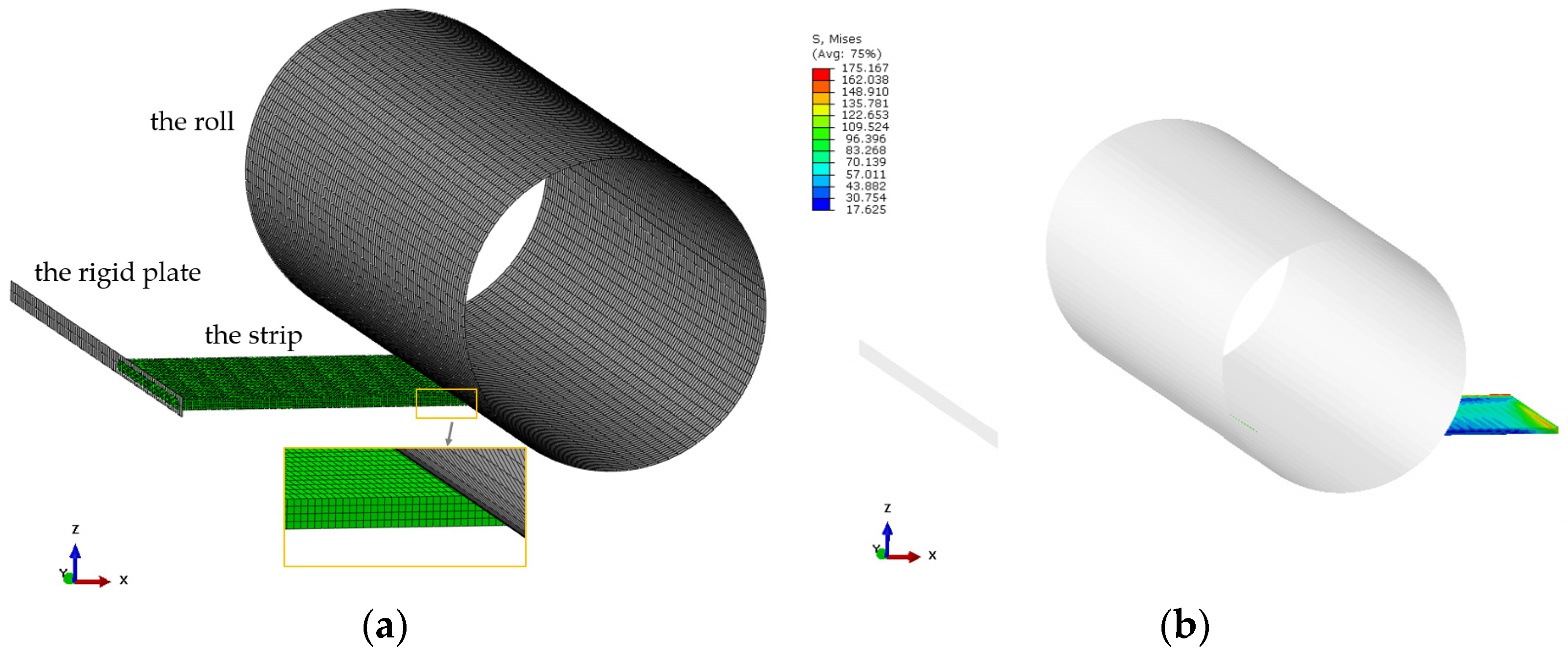
Figure 3.
The effect on transverse flow of friction factor m.

Figure 4.
(a) The effect on metal transverse flow of front tension stress and back tension stress; (b) variation of spread with front tension stress and back tension stress.
Figure 4.
(a) The effect on metal transverse flow of front tension stress and back tension stress; (b) variation of spread with front tension stress and back tension stress.
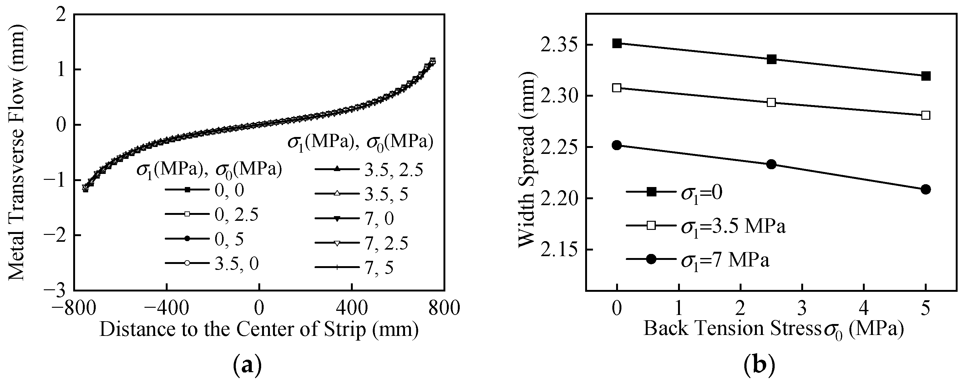
Figure 5.
The schematic figure of the experimental setup of metal transverse flow.

Figure 6.
(a) Metal transverse flow at each layer node of rolled strip with B = 700 mm; (b) metal transverse flow at each layer node of rolled strip with width B = 1400 mm; (c) metal transverse flow at each layer node of rolled strip with width B = 2100 mm.
Figure 6.
(a) Metal transverse flow at each layer node of rolled strip with B = 700 mm; (b) metal transverse flow at each layer node of rolled strip with width B = 1400 mm; (c) metal transverse flow at each layer node of rolled strip with width B = 2100 mm.

Figure 7.
(a) The effect on transverse flow of Ds with B = 700 mm; (b) the effect on transverse flow of Ds with B = 1400 mm; (c) the effect on transverse flow of Ds with s B = 2100 mm; (d) the effect on εc and εe of Ds under different B; (e) the comparison of flatness increment with Ds with and without the consideration of metal transverse flow.

Figure 8.
(a) The effect on transverse flow of Ds with H = 50 mm; (b) the effect on transverse flow of Ds with H = 30 mm; (c) the effect on transverse flow of Ds with H = 10 mm; (d) the effect on transverse flow of Ds with H = 6 mm.
Figure 8.
(a) The effect on transverse flow of Ds with H = 50 mm; (b) the effect on transverse flow of Ds with H = 30 mm; (c) the effect on transverse flow of Ds with H = 10 mm; (d) the effect on transverse flow of Ds with H = 6 mm.

Figure 9.
(a) The effect on εc and εe of Ds under different H; (b) the comparison of flatness increment with Ds with and without the consideration of metal transverse flow.
Figure 9.
(a) The effect on εc and εe of Ds under different H; (b) the comparison of flatness increment with Ds with and without the consideration of metal transverse flow.
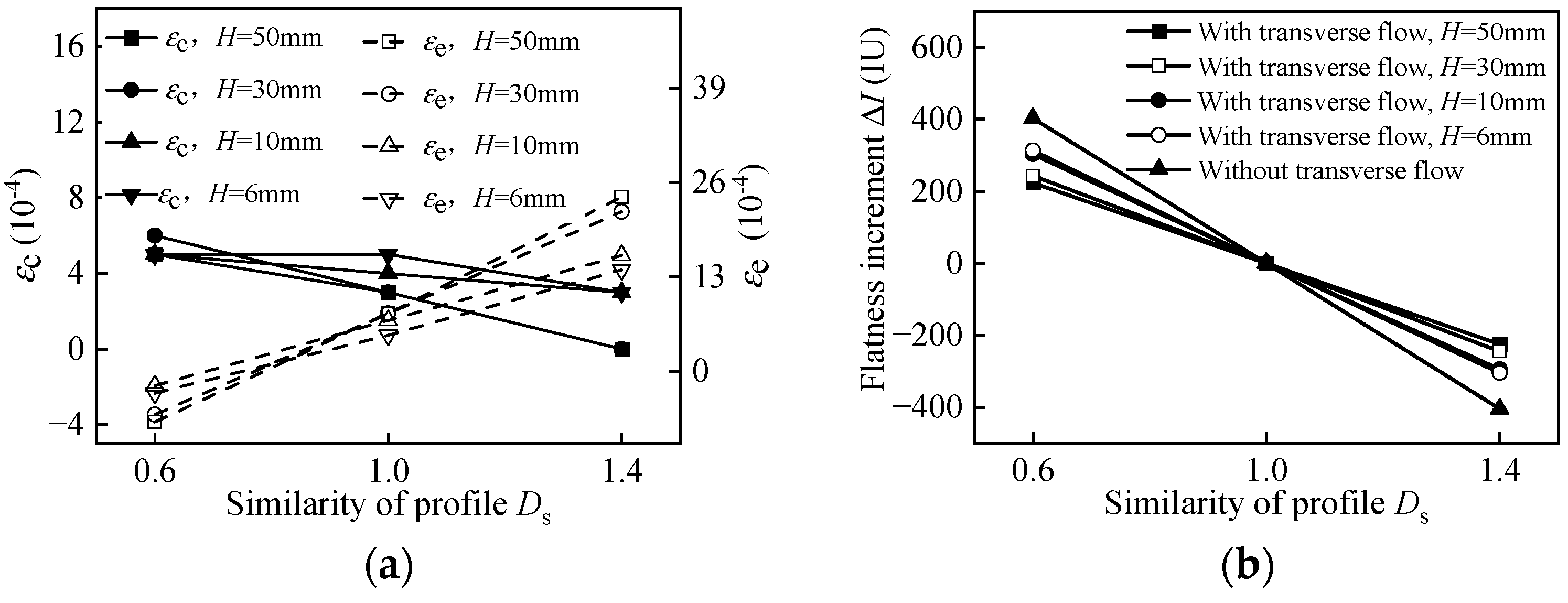
Figure 10.
(a) The effect on transverse flow of Ds with ε = 50%; (b) the effect on transverse flow of Ds with ε = 30%; (c) the effect on transverse flow of Ds with ε = 10%.
Figure 10.
(a) The effect on transverse flow of Ds with ε = 50%; (b) the effect on transverse flow of Ds with ε = 30%; (c) the effect on transverse flow of Ds with ε = 10%.

Figure 11.
(a) The effect on εc and εe of Ds under different ε; (b) the comparison of flatness increment with Ds with and without the consideration of metal transverse flow.
Figure 11.
(a) The effect on εc and εe of Ds under different ε; (b) the comparison of flatness increment with Ds with and without the consideration of metal transverse flow.


Table 1.
Inputs of the simulation model.
| Parameter | Value | Parameter | Value |
|---|---|---|---|
| roll diameter | 800 mm | strip entry thickness | 30 mm |
| roll length | 2550 mm | strip exit thickness | 18 mm |
| strip width | 1500 mm | strip velocity | 1.5 m/s |
| strip temperature | 933 °C | Poisson’s ratio | 0.3 |
| front tension stress | 0~7 MPa | back tension stress | 0~5 MPa |
Disclaimer/Publisher’s Note: The statements, opinions and data contained in all publications are solely those of the individual author(s) and contributor(s) and not of MDPI and/or the editor(s). MDPI and/or the editor(s) disclaim responsibility for any injury to people or property resulting from any ideas, methods, instructions or products referred to in the content. |
© 2023 by the authors. Licensee MDPI, Basel, Switzerland. This article is an open access article distributed under the terms and conditions of the Creative Commons Attribution (CC BY) license (https://creativecommons.org/licenses/by/4.0/).
Share and Cite
MDPI and ACS Style
Chai, X.; Li, Y.; Shang, F. Numerical Study on Metal Transverse Flow Law and Model of Rolled Strip under Variable Specification in Hot Rolling. Metals 2023, 13, 1876. https://doi.org/10.3390/met13111876
AMA Style
Chai X, Li Y, Shang F. Numerical Study on Metal Transverse Flow Law and Model of Rolled Strip under Variable Specification in Hot Rolling. Metals. 2023; 13(11):1876. https://doi.org/10.3390/met13111876
Chicago/Turabian StyleChai, Xiaojun, Yanlin Li, and Fei Shang. 2023. "Numerical Study on Metal Transverse Flow Law and Model of Rolled Strip under Variable Specification in Hot Rolling" Metals 13, no. 11: 1876. https://doi.org/10.3390/met13111876
Note that from the first issue of 2016, this journal uses article numbers instead of page numbers. See further details here.